Christie CP2000-ZX User Manual
Hide thumbs
Also See for CP2000-ZX:
- Setup manual (58 pages) ,
- Instruction sheet (5 pages) ,
- Quick setup manual (5 pages)
Table of Contents
Advertisement
Quick Links
Advertisement
Table of Contents
Troubleshooting

Subscribe to Our Youtube Channel
Related Manuals for Christie CP2000-ZX


Summary of Contents for Christie CP2000-ZX
- Page 1 CP2000-ZX U S E R M A N U A L 020-100006-05...
-
Page 3: Table Of Contents
2.10.2 Electronic Screen Masking ......................2-23 2.10.3 Projector Configuration Files (PCFs) ..................2-24 3 Operation 3.1 About Projector Components ......................3-2 3.1.1 Air Filter ............................ 3-2 3.1.2 Control Display Panel (CDP) ....................3-2 3.1.3 Douser............................3-2 CP2000-ZX User Manual 020-100006-05 Rev. 1 (05-2009) - Page 4 To Temporarily Alter the Active Channel ILS Settings .............3-16 Start Features or Presentations ....................3-16 3.4.4 Status Menu..........................3-17 Status: System Menu ........................3-17 Status: Test Menu ........................3-20 Status: Status Summary Menu ....................3-21 Status: SMPTE Errors Menu ......................3-21 Status: Interrogator Menu ......................3-22 CP2000-ZX User Manual 020-100006-05 Rev. 1 (05-2009)
- Page 5 3.6.2 Adjusting Lamp Power (LiteLOC™ or Manually) ..............3-51 Using LiteLOC™ ........................3-51 Adjusting Lamp Position (LampLOC™) ...................3-51 3.6.3 Age of a Lamp ...........................3-53 When to Replace a Lamp ......................3-53 Lamp Rotation ..........................3-53 Maintaining Footlamberts ......................3-53 CP2000-ZX User Manual 020-100006-05 Rev. 1 (05-2009)
- Page 6 4.2.2 Air Filter.............................4-4 4.2.3 Liquid Cooler ..........................4-4 Filling the Coolant Reservoir ......................4-5 4.2.4 Exhaust Duct and Lamp Fan Interlocks ..................4-5 4.3 Maintenance and Cleaning.........................4-6 4.3.1 Lamp ............................4-6 4.3.2 Optical ............................4-6 4.3.3 Cleaning the Lens........................4-6 CP2000-ZX User Manual 020-100006-05 Rev. 1 (05-2009)
- Page 7 5.6.10 Colors in the Display are Inaccurate..................5-6 5.6.11 The Display is Not Rectangular....................5-6 5.6.12 The Display is “Noisy” ......................5-7 5.6.13 There are Random Streaks on the Bottom of the Image............5-7 CP2000-ZX User Manual 020-100006-05 Rev. 1 (05-2009)
- Page 8 6.8 Environment............................6-6 6.9 Optional Components ........................6-6 6.10 Lamp Components ...........................6-7 6.11 Standard Components ........................6-7 Appendix A: Serial API Appendix B: SCCI Port Appendix C: GPIO C.1 The GPIO Port...........................C-2 Appendix D: CDP Error Codes CP2000-ZX User Manual 020-100006-05 Rev. 1 (05-2009)
-
Page 9: Introduction
Introduction This section includes information on the following: • 1.1 Using this Manual • 1.2 Purchase Record and Service Contacts • 1.3 Projector Overview CP2000-ZX User Manual 020-100006-05 Rev. 1 (05-2009) -
Page 10: Using This Manual
Disclaimer: Every effort has been made to ensure the information in this document is accurate and reliable. However, due to ongoing research, the information in this document is subject to change without notice. Christie Digital Systems assumes no responsibility for omissions or inaccuracies. -
Page 11: Purchase Record And Service Contacts
Purchase Record and Service Contacts Whether the projector is under warranty or the warranty has expired, Christie’s highly trained and extensive factory and dealer service network is always available to quickly diagnose and correct projector malfunctions. Complete service manuals and updates are available for all projectors. -
Page 12: Projector Overview
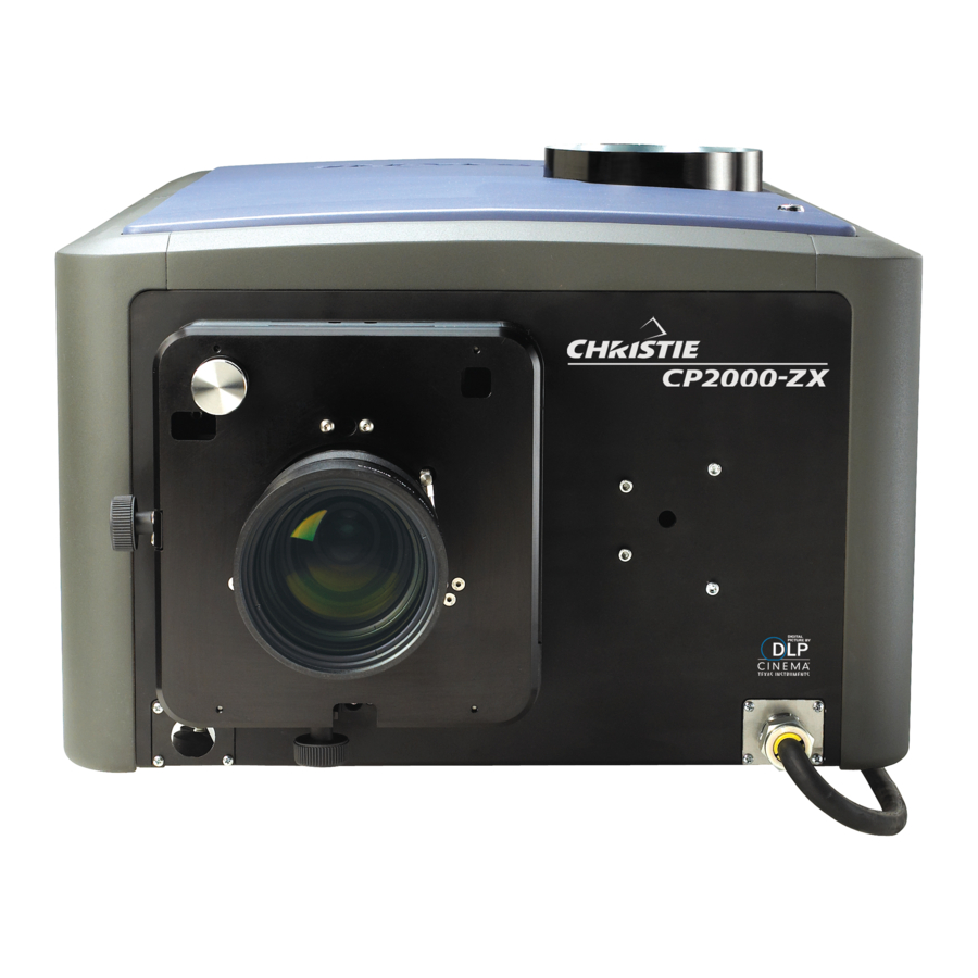
CP2000-ZX offers stunning wide screen, high-resolution cinema images that remain flawless from first release to final show. CP2000-ZX interfaces with local networks typical in theatres throughout the world, and can be expanded even further by connecting non-cinema DVI source material for multimedia presentations from a variety of formats. -
Page 13: How The Projector Works
1.3.3 User Interface Overview The CP2000-ZX incorporates two basic user interface systems: the Control Display Panel and the Web User Interface. The Control Display Panel (CDP) is a simple keypad with a small alphanumeric LCD display panel that can be backlit for easy viewing in dark projection rooms. -
Page 15: Installation & Setup
• 2.5 Initial Power Up • 2.6 Maximizing Light Output • 2.7 Basic Image Alignment • 2.8 Offset and Boresight Alignment • 2.9 Fold Mirror and Convergence Adjustments • 2.10 Calibrating the System CP2000-ZX User Manual 020-100006-05 Rev. 1 (05-2009) -
Page 16: Projector Installation
An optional rack stand (P/N 108-272101-01 or P/N 108-282101-01) and hold down clamp (P/N 116-100101- 01) are available for use with the projector. If you intend to use this in your installation, refer to the instructions provided with the rack stand before proceeding with STEP 3. CP2000-ZX User Manual 020-100006-05 Rev. 1 (05-2009) - Page 17 3. Once you have completed the remaining installation steps and the projector is up-and-running, adjust precise image geometry and placement as described in Section 2.7 Basic Image Alignment. CP2000-ZX User Manual 020-100006-05 Rev. 1 (05-2009)
- Page 18 6 ft (the max. length of the standard CDP harness). See Figure 2-4. NOTE: An optional 25ft CDP harness kit is available if more length is required (P/N 108-283101-01). Figure 2-4 CDP Mounting CP2000-ZX User Manual 020-100006-05 Rev. 1 (05-2009)
- Page 19 Regardless, check airflow regularly. Caution! Never disable the vane switch. Attempting to operate the projector with inadequate airflow can result in dangerous overheating of the projector. Figure 2-6 Exhaust Duct Vane Switch CP2000-ZX User Manual 020-100006-05 Rev. 1 (05-2009)
- Page 20 (WCL) producing 2.39:1 “scope” images for large screens, install the auxiliary lens mount and lens to the projector using the hardware and instructions provided in the Auxiliary Lens Mount Kit (P/N 108-111101-02, P/N 108-111102-xx). CP2000-ZX User Manual 020-100006-05 Rev. 1 (05-2009)
- Page 21 Check the position of the anode yoke assembly for the lamp type that will be used in the projector. Table 2.1 lists all available lamp types for the CP2000-ZX and the position of the anode yoke assembly. Table 2.1 Lamp Types Available for CP2000-ZX and Anode Yoke Position...
- Page 22 STEP 8 - Connect to Power CP2000-ZX is designed as a permanently wired connection or pluggable type B connection (P/N 116-102104- 01). Connecting the projector to your AC supply can vary according to the country or state in which the projector is installed.
- Page 23 Figure 2-11 Steps to Connect AC Power to Terminal Block 4. Once all cables are connected, replace the knockout plate and the bottom access panel over the terminal block. Figure 2-12 Re-attach Knockout and Access Panel Plates CP2000-ZX User Manual 020-100006-05 Rev. 1 (05-2009)
- Page 24 Figure 2-15 Steps to Connect AC Power to Terminal Block 4. Once all cables are connected, secure the knockout plate (four screws) and the bottom access panel (two screws) over the terminal block. 2-10 CP2000-ZX User Manual 020-100006-05 Rev. 1 (05-2009)
- Page 25 7. Adjust optical components when needed. In rare instances, the installer may have to adjust one or more optical components. Refer to Section 2.9 Fold Mirror and Convergence Adjustments for instructions. CP2000-ZX User Manual 2-11 020-100006-05 Rev. 1 (05-2009)
-
Page 26: Connecting Sources
PCM cover. Connect to Connect to AC at site AC at site (optional) Figure 2-16 Connecting an External Figure 2-16 Connecting Non-Cinema Cinema Server/Source Servers/Sources 2-12 CP2000-ZX User Manual 020-100006-05 Rev. 1 (05-2009) -
Page 27: Connecting For Communications
Depending on the installation, you may also need certain other serial and/or Ethernet links to the CP2000-ZX, such as from a server or PC functioning as a controller, or from an existing on-site network including other equipment. For applications or equipment utilizing serial communications, use the Christie-... -
Page 28: Re-Wiring For Uninterruptible Power Supply (Ups)
White facing down, L2 of LED Up Blue to N then screw into terminal 4. Tighten screws to Tighten to 14 in-lbs. 14 in-lbs Reattach cover. LVPS Figure 2-18 Re-wiring for UPS 2-14 CP2000-ZX User Manual 020-100006-05 Rev. 1 (05-2009) -
Page 29: Adjusting Tilt And Leveling
Disconnect the projector from the AC for these initial alignments. Images are not yet needed. For an ideal installation, the CP2000-ZX lens surface should be centered and parallel to the theatre screen. This orientation helps to ensure optimized lens performance with minimal offset. Choose a sturdy mounting surface that allows for this. -
Page 30: Initial Power Up
The lamp must be on and the douser (shutter) is opened during adjustment. Perform a white test pattern. This is recommended to allow you to view LampLOC™ progress on screen. 2-16 CP2000-ZX User Manual 020-100006-05 Rev. 1 (05-2009) -
Page 31: Calibrating Screen Brightness (Fl)
(stored in memory) from which the projector can interpolate all other lamp power settings by converting them to approximate footlamberts for display in the menus. Repeat the calibration if you switch to a different lamp type/size. Figure 2-21 Calibrating Screen Brightness Via Web UI CP2000-ZX User Manual 2-17 020-100006-05 Rev. 1 (05-2009) -
Page 32: Basic Image Alignment
Channel: Lens menu. Using the knobs on the lens mount to adjust these positions does not save the settings to the channel. They are designed for temporary use and will therefore be lost once the channel changes. Ensure the CP2000-ZX is properly positioned relative to the screen before you begin. 2.7.1 Basic Optical Alignment Procedure 1. -
Page 33: Adjust Offset
NOTE: Use a test pattern with a single pixel vertical and horizontal line and perimeter frame such as DC2K Framing or RGB Alignment. Figure 2-24 Horizontal Boresight CP2000-ZX User Manual 2-19 020-100006-05 Rev. 1 (05-2009) - Page 34 6. Repeat Steps 1 - 5 until both sides of the image are well focused. 7. Adjust the Horizontal Hold Screw to lock adjustments in place. Check boresight again. See Figure 2-24. 2-20 CP2000-ZX User Manual 020-100006-05 Rev. 1 (05-2009)
-
Page 35: Adjust Top/Bottom Boresight
8. Adjust the Vertical Hold Screw to lock the lens mount in place and check boresight again (Figure 2-27). For more information on ILS and channel setups, refer to Section Channel: Lens Menu, on page 3-30. CP2000-ZX User Manual 2-21 020-100006-05 Rev. 1 (05-2009) -
Page 36: Copy The Channel Settings To Another Channel
3. Pitch Adjustment: Adjust pitch, either up or down to equalize the top and bottom clearance to the prime lens barrel. 4. Yaw Adjustment: Adjust yaw to make the clearance between both lens barrels equal from side-to-side. 2-22 CP2000-ZX User Manual 020-100006-05 Rev. 1 (05-2009) -
Page 37: Fold Mirror And Convergence Adjustments
Configuration Files (PCFs) and specific source files necessary for proper display of incoming material. Through the web user interface, you can also define the system/network configuration for communication links to the projector and transmit information to and from the CP2000-ZX via an Ethernet or RS-232 connection. -
Page 38: Electronic Screen Masking
Section 2: Installation & Setup If there are changes to the environment in the future (for example, a new screen is installed), the CP2000-ZX should be re-calibrated. Also note that correction for proper color balance sometimes reduces overall light output. -
Page 39: Operation
3.4 Using the Web User Interface • 3.5 Upgrading and Downgrading Software • 3.6 Working with the Lamp • 3.7 Working with the Lenses • 3.8 Working with 3D • 3.9 Cinema Operation • 3.10 Non-Cinema Operation CP2000-ZX User Manual 020-100006-05 Rev. 1 (05-2009) -
Page 40: About Projector Components
For most cinema installations, the projector is inclined slightly forward to match screen tilt and to minimize the amount of vertical offset required. Turn the adjustable feet to increase or decrease the projector height as needed for proper leveling and/or slight tilt. Refer to Section 2.4.2 Adjusting Feet/Leveling. CP2000-ZX User Manual 020-100006-05 Rev. 1 (05-2009) -
Page 41: Lamps
Section 3: Operation 3.1.6 Lamps The CP2000-ZX can be used with either a 2.0kW or 3.0kW lamp, which is located on the non-operator’s side of the projector (right side). Table 3.1 Lamp Type Type Description 2.0 kW CDXL-20 3.0 kW CDXL-30 3.0 kW... -
Page 42: Auxiliary Panel
Appendix B: SCCI Port for SCCI pinouts. • 37-Pin GPIO - Connect external I/O devices, such as the Christie Automation Controller Theatre, for remote control of a limited number of projector functions. Refer to Appendix C: GPIO for GPIO pinouts. -
Page 43: Powering Down The Projector
NOTES: 1) The green status LED flashes while the yellow LED is on steady during “Boot Delay”. 2) Both green and yellow status LEDs flash during “Cool Down”. 3) To ensure activation of the CDP Power or Lamp keys, press firmly for 1/2 second. CP2000-ZX User Manual 020-100006-05 Rev. 1 (05-2009) -
Page 44: Using The Control Display Panel (Cdp)
• Press once to cancel a selection or go back one level in the menu. EXIT • If the back light turns OFF, push any key to turn it ON again. CP2000-ZX User Manual 020-100006-05 Rev. 1 (05-2009) -
Page 45: Navigating The Cdp Menus
Then use the arrow keys to ENTER scroll through a list of options or to adjust settings. Press while in a pull-down list to cancel. EXIT CP2000-ZX User Manual 020-100006-05 Rev. 1 (05-2009) -
Page 46: Using Slide Bar Controls
Gamma Lut-Clut Measured Color Source Format Target Color PCF File Use PCF 3D Control Channel Icon Lamp Per Channel Lamp Mode Lamp Power Intensity Aux Lens In Figure 3-3 CDP Channel Menu Options CP2000-ZX User Manual 020-100006-05 Rev. 1 (05-2009) -
Page 47: Lamp Menu
Focus and Zoom use the right/left arrow buttons to adjust the min./max Figure 3-5 CDP Lens Control values. The Horizontal (X) and Vertical (Y) values are fixed to ±2050 to Menu Options ensure the motor offsets are not overridden. CP2000-ZX User Manual 020-100006-05 Rev. 1 (05-2009) -
Page 48: Configuration Menu
Lens Calibration Since the CP2000-ZX can accommodate a number of different lenses, which all contain specific motor travel ranges, it is essential that lens calibration be performed each time a lens is installed. Calibration is critical for lens accuracy - it corrects system backlash and detects motor range for the installed lens. -
Page 49: Status Menu And Alarm Conditions
Test Patterns Menu The Test Patterns menu enables users to disable the test pattern feature or select from a list of test patterns used for troubleshooting and setup purposes. CP2000-ZX User Manual 3-11 020-100006-05 Rev. 1 (05-2009) -
Page 50: Using The Web User Interface
Operator level, but with the ability to add a new lamp in (lamp change is Status the Advanced: Lamp History menu. available to this user) > System Advanced > Lamp *excludes LiteLOC > Lamp History > Lens About 3-12 CP2000-ZX User Manual 020-100006-05 Rev. 1 (05-2009) - Page 51 > Lamp History > Lens > Test Pattern > User * can only set levels/users from it’s level & below Admin > Source > Screen > MCGD > TCGD > Network About CP2000-ZX User Manual 3-13 020-100006-05 Rev. 1 (05-2009)
-
Page 52: Navigating The Web User Interface
• Select a specific projector from within a network and see the assigned IP address. • View current time. • Change user level. • Close the screen and logout of the web user interface. • See current status of the selected projector. 3-14 CP2000-ZX User Manual 020-100006-05 Rev. 1 (05-2009) -
Page 53: Main Menu
Toggle the current location of the optional motorized auxiliary lens mount; position it either in front of the primary lens (enable Auxiliary Lens checkbox), or move it out (disable Auxiliary Lens checkbox). CP2000-ZX User Manual 3-15 020-100006-05 Rev. 1 (05-2009) -
Page 54: Intelligent Lens System (Ils)
Start Features or Presentations To start a different feature or presentation, click its corresponding display Channel button. NOTE: By clicking a channel button, test patterns are automatically turned OFF to present show content. 3-16 CP2000-ZX User Manual 020-100006-05 Rev. 1 (05-2009) -
Page 55: Status Menu
Displays manufacture date Projector subtype Projector subtype ID Light engine native resolution 2048 x 1080 Ballast ID Mgmt ID Address DLP IP Address Subnet Mask Gateway Aux IP Address Aux Subnet Mask CP2000-ZX User Manual 3-17 020-100006-05 Rev. 1 (05-2009) - Page 56 Red Formatter BitSequence version Green Formatter Boot version Green Formatter Main version Green Formatter Config version Green Formatter Gamma version Green Formatter BitSequence version Blue Formatter Boot version Blue Formatter Main version 3-18 CP2000-ZX User Manual 020-100006-05 Rev. 1 (05-2009)
- Page 57 292-A Total SMPTE error count 292-A Recent SMPTE error count 292-B Total SMPTE error count 292-B Recent SMPTE error count DDR memory test Flash memory test EDID checksum test FPGA checksum test CP2000-ZX User Manual 3-19 020-100006-05 Rev. 1 (05-2009)
-
Page 58: Status: Test Menu
(for example, a lost file, a server crash, loss of communication with the server, etc.) will appear in the window, and the Enable checkbox will clear. 3-20 CP2000-ZX User Manual 020-100006-05 Rev. 1 (05-2009) -
Page 59: Status: Status Summary Menu
List of SMPTE *Errors are displayed in inte- errors. gers not Hex values. Clear SMPTE errors from the log file. Returns error count back to zero. Figure 3-13 Status: SMPTE Error Menu CP2000-ZX User Manual 3-21 020-100006-05 Rev. 1 (05-2009) -
Page 60: Status: Interrogator Menu
Interrogator once a request to run it is applied. 5) Interrogator is also accessible through a separate login and password (different from the service login). Contact Christie tech support for assistance and password. Figure 3-14 Status: Interrogator Menu After you run Interrogator, you will be prompted to specify a location on your PC to save the Interrogator file. -
Page 61: How To Respond To An Alarm Window
ILS Online Status No Ensure the serial cord is plugged in. Serial cord may be damaged. ILS Power Status No Ensure the power supply is plugged in. Power supply may be damaged. CP2000-ZX User Manual 3-23 020-100006-05 Rev. 1 (05-2009) -
Page 62: Channel Menu
Select a screen file that iden- tifies the display area, mask- ing (cropping), and expected lens for current source (defined in Admin: Source). Other accessible Chan- Figure 3-17 Channel: Page 1 Menu Options nel menus. 3-24 CP2000-ZX User Manual 020-100006-05 Rev. 1 (05-2009) - Page 63 By enabling the Use PCF checkbox, you can select and implement a predefined PCF. Most applications such as cinema, post production and “alternative” or “non-cinema” displays require one or more display parameters to be individually adjusted. In this case, clear the Use PCF checkbox. CP2000-ZX User Manual 3-25 020-100006-05 Rev. 1 (05-2009)
-
Page 64: Channel: Page 2 Menu
* NOTE: Components marked with an asterisk (*) are part of any pre-defined PCF (Projector Configuration File) that controls image processing for a given source. When the “Use PCF” checkbox is checked, these components disappear from the Channel menu and are protected from further change. 3-26 CP2000-ZX User Manual 020-100006-05 Rev. 1 (05-2009) -
Page 65: Channel: 3D Control Menu
= start early. See Dark Time and Output Delay Notes below. Phase Delay Controls the degree of reference between the L/R sync output. A vertical adjustment is typically required when using a z-screen. CP2000-ZX User Manual 3-27 020-100006-05 Rev. 1 (05-2009) - Page 66 (-) or later (+). Adjust only as necessary—too much offset can cause “bleed-through” where each eye sees some data that is intended for the other, or causes color cropping since some DMD sequences may be clipped. 3-28 CP2000-ZX User Manual 020-100006-05 Rev. 1 (05-2009)
-
Page 67: Channel: Lamp Per Channel Menu
2200W (110%) CDXL-30 / CDXL- 30SD 1000W (33%) 3000W (100%) Christie provides a wide lamp power range to give flexibility in meeting different exhibition configurations. However, older lamps may not always strike at the lowest power settings. CP2000-ZX User Manual 3-29... -
Page 68: Channel: Lens Menu
Use the Copy Lens Settings to Channel feature to easily copy the settings from the current active Settings to channel to another channel. Select the channel from the drop-down list and click Copy to apply the Channel changes. Repeat for every channel that requires the same ILS values. 3-30 CP2000-ZX User Manual 020-100006-05 Rev. 1 (05-2009) -
Page 69: Channel: Lens Menu Disabled
In the instance that an ILS is not installed on the projector or if the ILS Installed option in the Advanced: Lens menu is not selected, an ILS Not Installed label is displayed. See Figure 3-24. Figure 3-24 Channel: Lens Menu Disabled CP2000-ZX User Manual 3-31 020-100006-05 Rev. 1 (05-2009) -
Page 70: Advanced Menu
Click the clock icon to reset the displayed time. Choose from 24-hour or standard 12-hour formats. Time is always displayed on each window in the chosen format. Time Zone - Choose the time-zone. 3-32 CP2000-ZX User Manual 020-100006-05 Rev. 1 (05-2009) -
Page 71: Advanced: Lamp Menu
This is a meter reading from the projector’s light sensor. Indicates the current light output (vertical bar) and LiteLOC™ level set (red horizontal line). The value at the top of the meter is shown in arbi- trary units-of -measure and does not represent actual lumens or fL. CP2000-ZX User Manual 3-33 020-100006-05 Rev. 1 (05-2009) -
Page 72: Advanced: Lamp History Menu
Enter the serial number of the newly installed lamp. Hours Enter the number of hours logged on the newly installed lamp. If the lamp has never been used the value should be “0”. 3-34 CP2000-ZX User Manual 020-100006-05 Rev. 1 (05-2009) -
Page 73: Advanced: Lens Menu
This feature is useful for initiating an auto lens reset. Each motor can either be reset individually or select All Axes when prompted to reset the 4 motors in suc- cession. CP2000-ZX User Manual 3-35 020-100006-05 Rev. 1 (05-2009) -
Page 74: Advanced: Test Patterns Menu
Main x 1080. menu. List of test patterns that are Click to transfer selected available from the Main menu. test patterns between two lists. Figure 3-29 Advanced: Test Pattern Menu Options 3-36 CP2000-ZX User Manual 020-100006-05 Rev. 1 (05-2009) -
Page 75: Advanced: User Menu
Enable to automatically enter the password when a user name is entered in the login window. CDP Password Resets the standard CDP password. Figure 3-31 Add User and Alter Permission Level Features CP2000-ZX User Manual 3-37 020-100006-05 Rev. 1 (05-2009) -
Page 76: Admin Menu
Save current settings as the selected source file, which will be accessible from the Channel: Page 1 menu. Restore Cancel new (unsaved) source settings of resolution, offset and aspect ratio. Test Apply current settings to the image without saving. 3-38 CP2000-ZX User Manual 020-100006-05 Rev. 1 (05-2009) - Page 77 Adding the 1.25x anamorphic lens widens a “squeezed” image back to its original “scope” aspect ratio. For sources that are not pre-squeezed, aspect ratio can be left at “0” (nothing selected in menu). CP2000-ZX User Manual 3-39 020-100006-05 Rev. 1 (05-2009)
-
Page 78: Admin: Screen Menu
Otherwise, you will overwrite the settings of the loaded screen file. Restore will not cancel a Save. Restore Cancel new (unsaved) screen settings and return to previously saved settings. 3-40 CP2000-ZX User Manual 020-100006-05 Rev. 1 (05-2009) - Page 79 Figure 3-35 Letter Box vs. Non-Letter Box and-bottom or left-and- right—will be discarded. NOTE: Check Letter Box for all cinema presentations. CP2000-ZX User Manual 3-41 020-100006-05 Rev. 1 (05-2009)
-
Page 80: Admin: Mcgd Menu
The old “OnSite” file cannot be recovered. See Save Notes below. Restore This button enables you to return to the gamut menu settings that were present when you opened the menu. See Restore Notes below. 3-42 CP2000-ZX User Manual 020-100006-05 Rev. 1 (05-2009) - Page 81 Each setup (channel) can then use any desired MCGD file as the basis for the color corrections needed for a target color. MCGD files are chosen in the Channel: Page 2 menu. NOTE: User created MCGD files can be deleted only by using Christie’s licensed DLP Control Application software. RESTORE NOTES The Restore button is disabled unless you have selected the Test button.
-
Page 82: Admin: Tcgd Menu
TCGD fields to confirm that the projected colors are accurate. For special applications in which you want to create a unique target color standard, enter new TCGD coordinates as desired and then save as a new TCGD file. Apply as usual from the Channel: Page 2 menu. 3-44 CP2000-ZX User Manual 020-100006-05 Rev. 1 (05-2009) -
Page 83: Admin: Network Menu
UI to change it - mance. do not use the DLP Con- trol Application. Address specific to SNMP network management sys- tem. Figure 3-38 Admin: Network Menu CP2000-ZX User Manual 3-45 020-100006-05 Rev. 1 (05-2009) -
Page 84: Admin: General Menu
Normal Rear, Inverted Front. Reboots the TI software. Select to close all commu- nication pipes with the TI firmware. This is used to install new TI software. Figure 3-39 Admin: General Menu Options 3-46 CP2000-ZX User Manual 020-100006-05 Rev. 1 (05-2009) -
Page 85: Admin: Lamp Menu
7. Click Apply to save the Max FL value. Once Apply is clicked, the Max Power button becomes unchecked and the Apply button becomes greyed-out. Lamp power returns to the lamp power it was before Max Power was clicked. CP2000-ZX User Manual 3-47 020-100006-05 Rev. 1 (05-2009) -
Page 86: About Menu
1. Perform the regular software load to go from v2.x to v1.1. Once the downgrade is complete, reboot the Figure 3-42 Failsafe Web Application projector by clicking the Reboot button in the failsafe web application. (Figure 3-42). 3-48 CP2000-ZX User Manual 020-100006-05 Rev. 1 (05-2009) - Page 87 Figure 3-44 Upgrade 4. Once the downgrade is complete, reboot the projector by clicking the Reboot button in the failsafe web application. The downgrade from 2.x to 1.1 is now complete. CP2000-ZX User Manual 3-49 020-100006-05 Rev. 1 (05-2009)
-
Page 88: Working With The Lamp
If this re-try also fails, and there is no interlock problem such as an open lamp door, a new lamp is likely needed. The power reverts back to what was originally defined in the menus by the user. 3-50 CP2000-ZX User Manual 020-100006-05 Rev. 1 (05-2009) -
Page 89: Adjusting Lamp Power (Liteloc™ Or Manually)
NOTES: 1) Before adjusting, a 10-minute warm-up is recommended. Also make sure to follow all the criteria specified in Section 2.5 Initial Power Up. 2) You can adjust lamp position either before or after adjustment of Lamp Power or LiteLOC™. CP2000-ZX User Manual 3-51 020-100006-05 Rev. 1 (05-2009) - Page 90 3. Re-adjust forward/aft (Z) as necessary. 4. Repeat Steps 1-3 as necessary. 5. Repeat Steps 1-4, but reading at the screen instead of at the lens. 6. Reset Lamp Power or LiteLOC if desired. 3-52 CP2000-ZX User Manual 020-100006-05 Rev. 1 (05-2009)
-
Page 91: Age Of A Lamp
Over time, as the theatre screen ages and dust and dirt collects on the port window, the theatre may no longer be achieving the expected footlamberts as reported. It is a good idea to periodically recalibrate footlamberts (Figure 3-40). CP2000-ZX User Manual 3-53 020-100006-05 Rev. 1 (05-2009) -
Page 92: Working With The Lenses
Zoom • From the Main menu, click ILS. Click the zoom in/out buttons to enlarge or shrink the image in each direc- tion as necessary. 3-54 CP2000-ZX User Manual 020-100006-05 Rev. 1 (05-2009) -
Page 93: Working With 3D
3D display without cross- talk, ghosting or other artifacts. 3.8.1 Requirements for 3D To display 3D, the CP2000-ZX requires a 3D capable SMPTE source and a few special hardware / software setups as described below: ... -
Page 94: Hardware Setup
For example, a setting of 6:2 creates 6 frames from 2 inputs (=144Hz). NOTE: Frame rate multiplication less than 6:2 may flicker at slow incoming frame rates. 3-56 CP2000-ZX User Manual 020-100006-05 Rev. 1 (05-2009) - Page 95 A is connected to projection input A and the cable connecting server output B is connected to pro- jection input B. CP2000-ZX User Manual 3-57 020-100006-05 Rev. 1 (05-2009)
-
Page 96: Troubleshooting
If the image seems to jump back and forth during horizontal pans, the L/R Display Sequence is likely backwards. Try reversing the current setting. Single 3D Input Not Working A single source signal containing both left and right data is not currently supported. 3-58 CP2000-ZX User Manual 020-100006-05 Rev. 1 (05-2009) -
Page 97: Cinema Operation
Table 3.24 in 4:4:4 YCbCr or RGB format with 10 or 12 bits per component. Also supported is the 4:2:2 YCbCr progressive input with 10 bits per components and a pixel format of 1920 x 1080 at 47.96 or 48fps. CP2000-ZX User Manual 3-59 020-100006-05 Rev. 1 (05-2009) -
Page 98: Image Formats
“Scope” source material can be resized electronically to fill the DMD and then its pixels are stretched through the anamorphic lens so that the full 2.39 image width appears on screen. Figure 3-52 Using Anamorphic Lens to Achieve “Scope” for Large Screens 3-60 CP2000-ZX User Manual 020-100006-05 Rev. 1 (05-2009) -
Page 99: Projector Variables: Using A Wide Converter Lens
• Bring in masking from sides for “flat” • Open masks for “scope” In some cases, a theatre has both side and top/bottom masking installed. This arrangement is the most flexible of all. Figure 3-55 Side Masking for Flat CP2000-ZX User Manual 3-61 020-100006-05 Rev. 1 (05-2009) -
Page 100: Non-Cinema Operation
RETURN TO A CINEMA SOURCE: input at port 292A or 292B from either the Main menu or from the —the projector now ignores CHANNEL LIST the DVI ports and responds to the cinema source selected. 3-62 CP2000-ZX User Manual 020-100006-05 Rev. 1 (05-2009) -
Page 101: Maintenance
This section contains: • 4.1 Safety Warnings and Guidelines • 4.2 Maintaining Proper Cooling • 4.3 Maintenance and Cleaning • 4.4 Replacing the Lamp • 4.5 Replacing the Filter • 4.6 Replacing the Lens CP2000-ZX User Manual 020-100006-05 Rev. 1 (05-2009) -
Page 102: Safety Warnings And Guidelines
4.1.2 General Precautions Be aware of the following general precautions in all CP2000-ZX installations: Warnings! 1) Never look directly into the projector lens or at the lamp. The extremely high brightness can cause permanent eye damage. 2) For protection from ultraviolet radiation, keep all projector housings intact during operation. -
Page 103: Ac / Power Precautions
AC has been fully disconnected from the product. 4.1.4 Lamp Precautions Any Xenon arc lamp used in the CP2000-ZX is under high pressure and must be handled with great care at all times. Lamps may explode if dropped or mishandled. DANGER! EXPLOSION HAZARD -Wear authorized... -
Page 104: Maintaining Proper Cooling
4.2.3 Liquid Cooler CHECK: Every 6 months The liquid cooler system circulates liquid to and from the DMD heatsinks in the CP2000-ZX reducing the DMD operating temperature to an acceptable level. Check the coolant level every 6 months, by removing the air filter door and viewing it through the grille. -
Page 105: Filling The Coolant Reservoir
Section 4: Maintenance Filling the Coolant Reservoir Top up the coolant level using the Christie approved coolant Jeffcool E105 and refill bottle with the nozzle provided in the Liquid Coolant Fill Service Kit (P/N 003-001837-02). Danger! HAZARDOUS SUBSTANCE - The coolant used in this product contains ethylene glycol. Use caution when handling. Do not ingest. -
Page 106: Maintenance And Cleaning
- use the tension in the folded cloth itself to collect dust. 3. If significant dust is still bound to the surface, dampen a clean microfibre cloth with coated optics cleaning solution (damp, not dripping). Wipe gently until clean. CP2000-ZX User Manual 020-100006-05 Rev. 1 (05-2009) -
Page 107: Cleaning The Reflector
1. Vacuum loose dirt from the lamp fan impeller. 2. If necessary, use a brush with hot water and suitable detergent. Igniter Clean the high voltage terminal and insulator to remove accumulated dust or dirt. CP2000-ZX User Manual 020-100006-05 Rev. 1 (05-2009) -
Page 108: Airflow Interlocks
Section 4: Maintenance Airflow Interlocks The CP2000-ZX uses two airflow interlocks; a lamp fan vane switch and an extractor vane switch. The lamp fan vane switch is located within the lamp cooling compartment. The extractor vane switch is located just inside the top duct on the projector lid. Check and clean the switches to remove accumulated dust or dirt that could impede movement if necessary. - Page 109 If you are installing any other lamp type, make sure this extension nut is removed. The purpose of the extension nut is to correctly position the lamp for opti- mal light output. CP2000-ZX User Manual 020-100006-05 Rev. 1 (05-2009)
- Page 110 The light shield should move freely to the touch. Figure 4-3 Lift Light Shield 4-10 CP2000-ZX User Manual 020-100006-05 Rev. 1 (05-2009)
-
Page 111: Replacing The Filter
Replacing the Filter Use only special, high efficiency Christie approved filters. Never operate the projector without the filter installed. Always discard used air filters. -
Page 113: Troubleshooting
NOTE: A qualified service technician is required when opening an enclosure to diagnose any probable cause. • 5.1 Power • 5.2 Lamp • 5.4 Ethernet • 5.5 Cinema Displays • 5.6 Non-Cinema Displays CP2000-ZX User Manual 020-100006-05 Rev. 1 (05-2009) -
Page 114: Power
5. Listen for a “clicking” noise to indicate the igniter is attempting to strike the lamp. If you do not hear anything, it may indicate a problem with the igniter (Christie service required). 6. If you hear a brief “click”, but no light appears, the lamp likely needs replacement. -
Page 115: Lamploc™ Does Not Seem To Work
3. If the lamp power has increased to its maximum in order to maintain a LiteLOC™ setting, LiteLOC™ is automatically terminated. If the values shown in the Advanced: Lamp menu indicate that the lamp power has reached this “over-drive” state, either reduce your LiteLOC™ setting or install a new lamp. CP2000-ZX User Manual 020-100006-05 Rev. 1 (05-2009) -
Page 116: Cdp
4. On the web user interface Main menu, Douser Open should be enabled ( 5. Ensure a full black test pattern is not selected for display. 6. Is the correct display file selected? 7. Verify the correct cinema port is connected for this display file. CP2000-ZX User Manual 020-100006-05 Rev. 1 (05-2009) -
Page 117: Severe Motion Artifacts
5.5.3 Image Appears Vertically Stretched or ‘Squeezed’ into Center of Screen Source data converted from film and “pre-squeezed” for CP2000-ZX display format may require use of the anamorphic lens (or resizing) to regain full “scope” image width and proper proportions. -
Page 118: The Display Is Faint
1. Check leveling of the projector. Ensure the lens surface and screen are parallel to one another. 2. Is the vertical offset correct? Adjust as necessary using the vertical offset knob. 3. Is the anamorphic lens straight? Rotate to orient aperture correctly. CP2000-ZX User Manual 020-100006-05 Rev. 1 (05-2009) -
Page 119: The Display Is "Noisy
1. If a 24Hz or 25Hz HD-SDI signal, or a 50 Hz SDI digital PAL signal is used, ensure non-cinema processing is selected. This can be implemented via the Channel: Page 1 menu of the web user interface by disabling the Cinema checkbox. NOTE: This is password-protected. CP2000-ZX User Manual 020-100006-05 Rev. 1 (05-2009) -
Page 121: Specifications
Specifications This section provides detailed CP2000-ZX specifications, including: • 6.1 Display • 6.2 Inputs • 6.3 Control Display Panel (CDP) • 6.4 Power Requirements • 6.5 Lamps • 6.6 Physical Specifications • 6.7 Regulatory • 6.8 Environment • 6.9 Optional Components •... -
Page 122: Display
= 0.351 +/- 0.002 6.1.6 Gamma Review Rooms (nominal) 2.6 +/-2% Theater (nominal) 2.6 +/-5% Inputs 6.2.1 Cinema Inputs • Number of inputs • Standard supported SMPTE 292M bit-serial • Connector type CP2000-ZX User Manual 020-100006-05 Rev. 1 (05-2009) -
Page 123: Non-Cinema Dvi Inputs (For Alternate Content)
PC communication (non-serial API) for direct DLP communication 9-pin D female 38,400 bps (default) RS232 B Port: Christie proprietary protocol intended for Christie accessories or automation controllers 9-pin D female 9600 bps (default) GPIO (1): 37-pin D female 16-8 inputs, 8 outputs, opto-isolated connection USB (1): USB device standard size 38.4 kbps... -
Page 124: Power Requirements
1.0 kW min. to 3.0 kW max. 6.4.4 UPS Input Voltage Range: 100-240 VAC Line Frequency: 50 Hz - 60 Hz sinusoidal Current: 10 A Power: 1000 W min. (NOTE: VA rating is not equivalent to Watts) CP2000-ZX User Manual 020-100006-05 Rev. 1 (05-2009) -
Page 125: Lamps
This product conforms to the following regulations related to product safety, environmental requirements and electromagnetic compatibility (EMC): • FCC Part 15, Subpart B Class A; CISPR22/EN55022; CISPR24/EN55024 • UL 60950-1 First Edition; CAN/CSA-C22.2 No 60950-1-03 First Edition; • IEC60950-1:2001 • 2002/95/EC RoHS CP2000-ZX User Manual 020-100006-05 Rev. 1 (05-2009) -
Page 126: Environment
100% (vertical), 70% (horizontal) 2.2 - 3.0:1 108-277101-01 100% (vertical), 70% (horizontal) 3.0 - 4.3:1 108-278101-01 100% (vertical), 70% (horizontal) 4.3 - 6.0:1 108-279101-01 100% (vertical), 70% (horizontal) 5.5 - 8.5:1 108-280101-01 100% (vertical), 70% (horizontal) CP2000-ZX User Manual 020-100006-05 Rev. 1 (05-2009) -
Page 127: Lamp Components
3.0kW CDXL-30 003-000599-02 3.0kW CDXL30SD 003-001165-01 6.11 Standard Components • Control Display Panel with interface cable • CP2000-ZX User’s Manual • Interconnect Drawing Other Part # 598900-095 Protective Clothing Kit (for opening of lamp door) DLP Cinema Firmware Installation Program... -
Page 129: Appendix A: Serial Api
Appendix A: Serial API CP2000-ZX User Manual 020-100006-05 Rev. 1 (05-2009) - Page 130 (AML+LENI -300) Move lens to -300 for lens in position (AML+LENO 6000) Move lens to 6000 for lens out position (AML+POSI ?) Query where the lens is (AML+CSTA ?) Query how much percent the MALM calibration is running CP2000-ZX User Manual 020-100006-05 Rev. 1 (05-2009)
- Page 131 Emergency Stop (BGT) DESCRIPTION - Emergency Stop for commands that are running in a separate thread. SUBCODE DESCRIPTION OF USE STOP Action command (no argument required) EXAMPLES: (BGT+STOP) Stop any currently running control threads CP2000-ZX User Manual 020-100006-05 Rev. 1 (05-2009)
- Page 132 (CDP+BACK 0) Disable the backlight (CDP+BACK 100) Set the backlight to full brightness (CDP+PASS “CHRISTIE”) Set CDP password to “CHRISTIE” Channel (CHA) DESCRIPTION - Select Channel configuration to use. Channel range is 101 to 164. Channel configuration sets the input rout- ing and image processing options for input signals.
- Page 133 (DTF 1) or (DTF "422 Packed 12Bit") Set current data format to 1 (292: 422 Packed 12Bit) (DTF+C108?) Get data format on channel 108 (DTF+C108 20) or (DTF+C108 "Unpacked 8Bit") Use data format 20 (DVI: Unpacked 8Bit) on channel 1 CP2000-ZX User Manual 020-100006-05 Rev. 1 (05-2009)
- Page 134 (FCD -1) Set negative direction (FCS 500) Move lens to position 500 at focus motor (FCS+CXXX -500) Set lens to position of channel XXX to -500 at focus motor (FCS ?) Return current motor position CP2000-ZX User Manual 020-100006-05 Rev. 1 (05-2009)
- Page 135 DESCRIPTION - Query a list of all available serial commands with brief descriptions and current enabled states. SUBCODE DESCRIPTION OF USE NONE Request entire command help listing or list for a single command EXAMPLES: (HLP?) Retrieve entire command help listing (HLP? “BRT”) Retrieve all subcodes/descriptions/enables for BRT control CP2000-ZX User Manual 020-100006-05 Rev. 1 (05-2009)
- Page 136 (ITP+NOCR 1) Set non-correction test patterns for measured color you can use (ITP+RFSH 1) Refresh TI file list (ITP+STUP “DC2K Framing Green, DC2K Framing Red”) Add these two test patterns to the user list CP2000-ZX User Manual 020-100006-05 Rev. 1 (05-2009)
- Page 137 Replace xxx with the channel number. Valid Range is 101 - 164. NONE Select CUT for the current channel EXAMPLES: (LCT+C108 “9x9x9”) Use PCF file “9x9x9” on channel 108 (LCT+C108?) Get LUT-CULT file name on channel 108 (LCT?L) List all entries of LUT-CLUT control CP2000-ZX User Manual 020-100006-05 Rev. 1 (05-2009)
- Page 138 Motor moving range in negative direction, read-only for ILS EXAMPLES: (LHD -1) Set positive direction (LHO 500) Move lens to position 500 at horizontal motor (LHO+CXXX -500) Set lens to position of channel XXX to -500 at horizontal motor A-10 CP2000-ZX User Manual 020-100006-05 Rev. 1 (05-2009)
- Page 139 DESCRIPTION - Adjust all lens position parameters simultaneously. SUBCODE DESCRIPTION OF USE NONE (LMV <lho><lvo><zom><fcs>) where <lho>, <lvo>, <zom>, and <fcs> represent the horizontal, vertical, focus, and zoom position infor- mation. EXAMPLES: (LMV 1000 1500 500 -500) CP2000-ZX User Manual A-11 020-100006-05 Rev. 1 (05-2009)
- Page 140 Return Total lamp unexpected off times on the installed lamp NONE Return Lamp usage for current lamp in hours. TLSK Return Total lamp strikes on the installed lamp EXAMPLES: (LPH?) Get usage in hours (LPH+FLSK?) Get lamp strikes A-12 CP2000-ZX User Manual 020-100006-05 Rev. 1 (05-2009)
- Page 141 (LOL 0) Set lamp life limit to default hours based on the lamp type (LPL ?) Get lamp life limit (LPL+LIFE 1) Enable lamp expired message. (LPL+LIFE 0) Disable lamp expired message. (LPL+ROTW 1) Enable lamp rotation message. (LPL+ROTA 1) Acknowledge that lamp was rotated. CP2000-ZX User Manual A-13 020-100006-05 Rev. 1 (05-2009)
- Page 142 DESCRIPTION - Get/set the current vertical direction SUBCODE DESCRIPTION OF USE None (LVD {1 | -1}) EXAMPLES: (LVD 1) set vertical direction to positive (LVD?) return current vertical direction (1 or -1) A-14 CP2000-ZX User Manual 020-100006-05 Rev. 1 (05-2009)
- Page 143 (MCG+C108?) Get measured color file name on channel 108 (MCG?L) List all entries of measured color control (MCG+TEMP “Nominal”) Use file “Nominal” as DLP active file (MCG+RFSH 1) Refresh TI file list CP2000-ZX User Manual A-15 020-100006-05 Rev. 1 (05-2009)
- Page 144 DESCRIPTION - Set routing for ASCII messages SUBCODE DESCRIPTION OF USE NONE Used to enable or disable daisy chaining EXAMPLES: (NTR ?1) List routing options. (NTR 0) Each connection is routed separately. (NTR 3) Full daisy-chaining A-16 CP2000-ZX User Manual 020-100006-05 Rev. 1 (05-2009)
- Page 145 NONE Select pull-down Sequence for the current channel. EXAMPLES: (PDS?L) List all entries on pull-down sequence control (PDS+C101 1) Set pull-down sequence on channel 101 (PDS+C101?) Get pull-down sequence on channel 101 CP2000-ZX User Manual A-17 020-100006-05 Rev. 1 (05-2009)
- Page 146 Select processing mode for the current channel EXAMPLES: (PRM+C108 1) Use cinema processing mode on channel 108 (PRM+C108 0) Do not use cinema processing mode on channel 108 (PRM?) Get current processing mode A-18 CP2000-ZX User Manual 020-100006-05 Rev. 1 (05-2009)
- Page 147 Table A.2 Projector Power Modes NOTES: 1) The green status LED flashes while the yellow LED is on steady while in “Boot Delay”. 2) Both green and yellow status LEDs flash during “Cool Down. CP2000-ZX User Manual A-19 020-100006-05 Rev. 1 (05-2009)
- Page 148 Set SMPTE Field Bit for the current channel. EXAMPLES: (SFB?L) List all entries on SMPTE Field Bit control (SFB+C101 1) Set SMPTE Field Bit to 1 on channel 101 (SFB+C101?) Get SMPTE Field Bit on channel 101 A-20 CP2000-ZX User Manual 020-100006-05 Rev. 1 (05-2009)
- Page 149 None Select douser position 0 - douser removed from optical path 1 - douser blocking optical path STEP Change the steps for open/close douser on CP2000-ZX. The default value is 50. EXAMPLES: (SHU 1) Close shutter (SHU 0) Open shutter...
- Page 150 (SRF+C108 “XXX”) Use file “XXX” on channel 108 (SRF+C108?) Get source file name on channel 108 (SRF?L) List all entries of source control (SRF+TEMP “XXX”) Use file “XXX” as DLP active file (SRF+RFSH 1) Refresh TI file list A-22 CP2000-ZX User Manual 020-100006-05 Rev. 1 (05-2009)
- Page 151 DESCRIPTION OF USE NONE 0 - restart DLP communications; 1 - stop DLP communications. EXAMPLES: (STP 0) Restart DLP communication (STP 1) Stop DLP communication (STP?) Request current state. Example response if (STP!000) CP2000-ZX User Manual A-23 020-100006-05 Rev. 1 (05-2009)
- Page 152 DESCRIPTION - Stores the projector platform and motherboard related information. SUBCODE DESCRIPTION OF USE MCBI 0/1 - Set software flag to use/not use ILS on CP2000-ZX. MOTH Read motherboard revision of the projector. PLAT Read platform ID of the projector.
- Page 153 Select display reference for the current channel EXAMPLES: (TDR?L) List all entries on display reference control (TDR+C101 1) Set display reference to 1 on channel 101 (TDR+C101?) Get display reference on channel 101 CP2000-ZX User Manual A-25 020-100006-05 Rev. 1 (05-2009)
- Page 154 Select Input reference GPI for the current channel EXAMPLES: (TGI?L) List all entries on Input Reference GPI control (TGI+C101 1) Set Input Reference GPI to 1 on channel 101 (TGI+C101?) Get Input Reference GPI on channel 101 A-26 CP2000-ZX User Manual 020-100006-05 Rev. 1 (05-2009)
- Page 155 Select GPO for the current channel EXAMPLES: (TOO?L) List all entries on Output Reference GPO control (TOO+C101 1) Set Output Reference GPO to 1 on channel 101 (TOO+C101?) Get Output Reference GPO on channel 101 CP2000-ZX User Manual A-27 020-100006-05 Rev. 1 (05-2009)
- Page 156 DESCRIPTION - Get/set the current zoom direction. SUBCODE DESCRIPTION OF USE None (ZOD {1 | -1}) EXAMPLES: (ZOD 1) set zoom direction to positive (ZOD?) return current zoom direction (1 or -1) A-28 CP2000-ZX User Manual 020-100006-05 Rev. 1 (05-2009)
- Page 157 Motor moving range in negative direction, read-only for ILS. EXAMPLES: (ZOD -1) Direction from the left (ZOM 500) Move lens to position 500 (ZOM+CXXX -500) Set lens to position of channel XXX to -500 (ZOM ?) Return current motor position CP2000-ZX User Manual A-29 020-100006-05 Rev. 1 (05-2009)
-
Page 159: Appendix B: Scci Port
Appendix B: SCCI Port CP2000-ZX User Manual 020-100006-05 Rev. 1 (05-2009) - Page 160 Open Connector High = Lamp ON Ground Ground NOTE: All SCCI inputs require a pulse input of 50ms to several seconds to operate reliably. Inputs are 5V resistor current limited LED’s inside of optocouplers. CP2000-ZX User Manual 020-100006-05 Rev. 1 (05-2009)
-
Page 161: Appendix C: Gpio
Appendix C: GPIO CP2000-ZX User Manual 020-100006-05 Rev. 1 (05-2009) -
Page 162: The Gpio Port
Figure C-1 Circuit for Power Supply If you are wiring your own GPIO cable for use with a server or 3D device such as an IR emitter or a polarizer, follow the circuit diagram Figure C-1, above. CP2000-ZX User Manual 020-100006-05 Rev. 1 (05-2009) -
Page 163: Appendix D: Cdp Error Codes
Appendix D: CDP Error Codes CP2000-ZX User Manual 020-100006-05 Rev. 1 (05-2009) - Page 164 DLP State ELogin Login to TI by Ethernet Port Error DLP State Selftest TI Powerup Self Test Error DLP State RDRAM TI RDRAM Signature Test Error DLP State FmtBrd TI Formatter Board Error CP2000-ZX User Manual 020-100006-05 Rev. 1 (05-2009)
Need help?
Do you have a question about the CP2000-ZX and is the answer not in the manual?
Questions and answers