Table of Contents
Advertisement
Quick Links
Advertisement
Table of Contents

Related Manuals for Christie CP2000


Summary of Contents for Christie CP2000
- Page 1 CP2000 S E T U P G U I D E 020-100070-01...
- Page 3 China RoHS Compliance Information 关于中国《电子信息产品污染控制管理办法》的说明 Environmentally Friendly Use Period 环保使用期限 The year number in the centre of the label indicates the Environmentally Friendly Use Period, which is required to mark on the electronic information product sold in China according to the China RoHS regulations.
-
Page 5: Table Of Contents
2.1 Assembly and Connection of Components..............2-2 2.1.1 Before Beginning .....................2-2 2.1.2 Projector Head and Pedestal ..................2-3 Secure Projector Head to Pedestal ................2-3 Position CP2000 at Port Window ................2-4 Extend all Feet ......................2-5 Install TPC ........................2-5 Connect Pre-installed Cabling (Pedestal-to-Head) ...........2-6 Connect Two Cooling Hose Ends (Pedestal-to-Head) ..........2-11... - Page 6 4.2.4 Exhaust Duct and Lamp Fan Interlocks ..............4-5 4.3 Maintenance and Cleaning ....................4-6 4.3.1 Electrical ........................4-6 4.3.2 Optical ........................4-6 When to Check ......................4-6 Supplies for Removing Dust and/or Grease .............4-6 Cleaning Lens ......................4-7 Cleaning Reflector ....................4-7 CP2000 Setup Guide 020-100070-01 Rev. 1 (10/08)
- Page 7 5.6.3 The Display is Faint ....................5-6 5.6.4 Upper Portion of Display Waving, Tearing or Jittering...........5-6 5.6.5 Portions of Display Cut-off or Warp to the Opposite Edge ........5-6 5.6.6 Display Appears Compressed (Vertically) ..............5-6 CP2000 Setup Guide 020-100070-01 Rev. 1 (10/08)
- Page 8 5.6.8 Display Quality Appears to Drift from Good to Bad and Vice Versa .....5-6 5.6.9 Display Suddenly Freezes ..................5-6 5.6.10 Display Colors Not Accurate .................5-7 5.6.11 Display Not Rectangular ..................5-7 5.6.12 Display is “Noisy” ....................5-7 5.6.13 Random Streaks at Bottom of Image ..............5-7 CP2000 Setup Guide 020-100070-01 Rev. 1 (10/08)
-
Page 9: Introduction
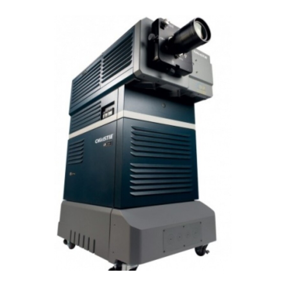
1 Introduction The content of this manual applies to the following products only: • CP2000-i models • CP2000-h models • CP2000-S* models - See also enclosed addendum for CP2000-S ballast configuration and additional specifications. THE PROJECTOR The CP2000 is a professional quality, easy-to-use DMD ... -
Page 10: How The Projector Works
• High-security tamper-resistant lid lock, with all access electronically monitored 1.1.2 HOW THE PROJECTOR WORKS The CP2000 accepts a variety of cinema or DVI-compatible “non-cinema” signals for projection on front screens typical in a commercial theatre or other large screen applications. High brightness light is generated by a short arc Xenon lamp, then modulated by three DMD (Digital Micromirror Device) panels responding to incoming data streams of digitized red, green or blue color information. -
Page 11: Purchase Record And Service Contacts
Should you encounter a problem with any part of the projector and require assistance, contact your dealer or one of the Christie service depots listed on the back cover of this manual. In most cases, CP servicing is performed on site. If you have purchased the projector, fill out the information on the following page and keep with your records. -
Page 12: Ethernet Settings For This Projector
Section 1: Introduction ETHERNET SETTINGS FOR THIS PROJECTOR The following Ethernet settings were defined during installation of the CP2000 and the Touch Panel Controller (TPC): Ethernet Settings for This Projector Default Gateway: DNS Server: CP2000-SB Projector Address Projector: Subnet Mask:... -
Page 13: Installation And Setup
• Laptop computer with DCP Librarian software with Ethernet or standard RS-232 cable • Vapor-free “dustoff type” compressed air can • Latex lab gloves • Lens cleaning tissue and solution (see 6.3, Maintenance & Cleaning) CP2000 Setup Guide 020-100070-01 Rev. 1 (10/08) -
Page 14: Projector Head And Pedestal
Section 2: Installation and Setup • - Refer to the provided. For CP2000-S Models Addendum for Installation and Use 2.1.2 PROJECTOR HEAD AND PEDESTAL SECURE PROJECTOR HEAD TO PEDESTAL WARNING It is recommended that two people perform the following procedure. -
Page 15: Position Cp2000 At Port Window
Section 2: Installation and Setup POSITION CP2000 AT PORT WINDOW Roll the projector until its base is approximately 2 feet from the port window wall, 3 feet if an anamorphic lens mount is going to be added (optional). If possible, center with the theatre screen () (Figure 2-2 Centering ¨... -
Page 16: Install Tpc
(or two IEC power sockets). NOTE: For all cable connections, keep cable ties that have been trimmed at manufacture. Remove temporary untrimmed ties that have "tails". CP2000 Setup Guide 020-100070-01 Rev. 1 (10/08) - Page 17 Panel C is pre-connected to Panel B and the remaining third connector is a non-functional spare. 2-6 C RS-232 IGURE ONNECT ALLAST NTERLOCKS TO ROJECTION NOTE: These cables also connect to the fire alarm interlock and dedicated outlet (both pre-connected at manufacture). CP2000 Setup Guide 020-100070-01 Rev. 1 (10/08)
- Page 18 (Figure 2-8). No other components or external equipment should be connected here. NOTE: This is a current-limited 120 VAC outlet powered by the ballast and separately fused. 2-8 C IGURE HECK THERNET ONNECTIONS TO CP2000 Setup Guide 020-100070-01 Rev. 1 (10/08)
- Page 19 PCB attached-stack this on top of the lamp lead (Figure 2-9 Route Lamp Leads Up and Connect Positive (+) White). • Close and lock the igniter door. 2-9 R (+) W IGURE OUTE EADS P AND ONNECT OSITIVE HITE CP2000 Setup Guide 020-100070-01 Rev. 1 (10/08)
- Page 20 • A universal connector nut should be pre-installed on the cathode-end lamp post. Regardless of model or lamp size, this nut is 1.658" in overall length (Figure 2-12). NOTE: The universal nut shown accommodates all models. Do not install a shorter nut. 2-12 C IGURE ONNECTOR CP2000 Setup Guide 020-100070-01 Rev. 1 (10/08)
-
Page 21: Connect Two Cooling Hose Ends (Pedestal-To-Head)
During operation, a closed loop of flexible tubing circulates cooling liquid stored in the pedestal to critical electronic components located in the front compartment of the projection head (Figure 2-14 Liquid Cooling Loop). Looking into the pedestal, the liquid will circulate counterclockwise. 2-14 L IGURE IQUID OOLING CP2000 Setup Guide 020-100070-01 Rev. 1 (10/08) -
Page 22: Fill The Reservoir Completely (Initial Filling For Hoses Only)
Avoid "forcing" together and listen for "click". FILL THE RESERVOIR COMPLETELY (INITIAL FILLING FOR HOSES ONLY) After connecting the hoses, completely fill the cooler reservoir with Christie's 50/50 mix of distilled water and ethylene glycol (Figure 2-16). -
Page 23: Check Lead Dressing And Hoses
Confirm that 1) there are no obstructions or “kinks” within the ducting, 2) all air intake areas of the CP2000 are clear and exposed, and 3) the vane switch at the exit duct is moving freely. The pre-installed outside-venting duct... -
Page 24: Install Lens(Es)
* For this projector, the 2.0 kW is available in CDXL (maximum performance) only ** Available as CDXL (maximum performance) or original CXL (less expensive). Refer to full specifications in Section 8 of User MAnual 2-12 CP2000 Setup Guide 020-100070-01 Rev. 1 (10/08) -
Page 25: Review Lamp Pre-Wiring
Observe all warnings, and wear protective clothing and shielding. 2.1.6 CONNECTING TO POWER NOTE: For CP2000-S Models - Refer to the Addendum for Installation and Use provided. Before connecting to AC, configure the lamp ballast to match the AC available at the site. - Page 26 • Ensure ground wire is connected directly to the frame ground lug on the pedestal floor. Attach no other wires here. • Connect 1, 2, and 3 @ 180-235 VAC (3-phase) • No L or N available, so the internal outlet will not be functional. 2-14 CP2000 Setup Guide 020-100070-01 Rev. 1 (10/08)
-
Page 27: Special Adjustments For Some Ac Supplies
T2. This configuration is used when 207-265 VAC are present (as it is for most countries). If you find your incoming AC is below 207 VAC, connect terminal 2 jumper to T1 instead. 2-21 C IGURE HECK OLTAGE AND OSITION UMPERS CP2000 Setup Guide 2-15 020-100070-01 Rev. 1 (10/08) -
Page 28: Installing And Connecting Sources
• If External: Source/server cabling routes through the pedestal toe and up to the underside of the projection head. Limit cable length to 300 feet or less. Connect power externally or within the pro- 2-16 CP2000 Setup Guide 020-100070-01 Rev. 1 (10/08) - Page 29 • If Internal: Sources/servers are often rack-mounted in the projector rear, with cabling routed directly to the underside of the projection head. Refer to Figure 2-25 and Figure 2-26 (shown are models with internal outlet for North America, etc.). To Install: CP2000 Setup Guide 2-17 020-100070-01 Rev. 1 (10/08)
- Page 30 2-26 C (DVI) S IGURE ONNECTING AN NTERNAL CINEMA OURCE NOTE: The DVI ports are single-link ports for single-link cable/connectors only. Using as a dual-link pair requires a special adapter (not currently available). 2-18 CP2000 Setup Guide 020-100070-01 Rev. 1 (10/08)
-
Page 31: Support For Internal Servers/Sources
Depending on the installation, you may also need certain other serial and/or Ethernet links to the CP2000, such as from a server or PC functioning as a controller, or from an existing on-site network including other equipment. Connections are typically done at time of installation, and then the projector is locked and protected from unauthorized changes. -
Page 32: Adjust Tilt And Leveling
NOTE: Disconnect from AC for these initial alignments. Images are not yet needed. In an ideal installation, the CP2000 lens surface is centered with and parallel to the screen. This orientation helps ensure optimized lens performance with minimal offset (Figure 2-28). If this position is not possible (such as when the projector is significantly higher than the center of the screen), it is better to rely on offset rather than tilt. - Page 33 1. Remove the rear bottom panel (two top screws, two bottom tabs) from the CP pedestal (Figure 2-30). 2-30 O IGURE EAR OF ROJECTOR 2. Use a low-profile scissor jack to elevate the rear of the projector. CP2000 Setup Guide 2-21 020-100070-01 Rev. 1 (10/08)
-
Page 34: Initial Power Up
1. With all components installed and connected, power-up the projector, as described in 3.1 Power- Up Procedure/Steps 1 and IMPORTANT! Do not ignite the lamp until the lamp type is defined in the TPC Install menu (Step 6). 2-22 CP2000 Setup Guide 020-100070-01 Rev. 1 (10/08) - Page 35 2. Upon initial power up, your first supply of coolant will drain into the hoses and fill them, leaving the reservoir itself almost empty. Using Christie's 50/50 mix of distilled water and ethylene glycol, re-fill the reservoir until the level is close to but not above the top mark on the gauge located on the outside of the pedestal door (Figure 2-32).
-
Page 36: Maximizing Light Output
This procedure ensures the image reflected from the DMDs is parallel to and well-centered with both the lens and screen. This initial optical alignment is the foundation for optimizing images on the screen and must be completed before final boresight adjustments. Before beginning the CP2000 must be properly positioned relative to the screen. -
Page 37: Offset And Boresight Alignment
NOTE: For best optical performance, make sure to minimize offsets by "aiming" the projector lens at the center of the image. The maximum vertical offset is shown in Figure 2-37/ bottom. 2-36 O IGURE FFSETS CP2000 Setup Guide 2-25 020-100070-01 Rev. 1 (10/08) -
Page 38: Adjust Left/Right Boresight
(i.e., the right side of the image is well-focused either in front of or behind the screen surface rather 2-38 A IGURE DJUST OCUS AT than on it). 2-26 CP2000 Setup Guide 020-100070-01 Rev. 1 (10/08) - Page 39 4. Adjust horizontal offset to re-center the image on the screen. 5. Repeat Steps 3 and 4 until both sides are well-focused. 6. Adjust the "hold" screw to lock in place. Recheck boresight. 2-40 A L/R B IGURE DJUST ORESIGHT CP2000 Setup Guide 2-27 020-100070-01 Rev. 1 (10/08)
-
Page 40: Adjust Top/Bottom Boresight
The goal is good focus at center and on all sides. 2-43 F (ANAMORPHIC) IGURE OCUS If horizontal focus in the image needs improvement, focus the FOCUS ANAMORPHIC LENS: anamorphic lens too—rotate its barrel as needed. 2-28 CP2000 Setup Guide 020-100070-01 Rev. 1 (10/08) -
Page 41: Fold Mirror And Convergence Adjustments
DCP Librarian also defines the system/network configuration for communication links to the projector, transmitting information to and from the CP2000 via an Ethernet or ‘RS-232’ connection. Chief functions, many of which can be done at the TPC, are introduced below. -
Page 42: Color Calibration
Section 2: Installation and Setup 2.10.1COLOR CALIBRATION After the CP2000 is installed and all components are mechanically aligned for optimized light output and geometry at the screen, its electronic system processing must be calibrated to ensure accurate color display in the new environment. In this one-time global calibration, the installer measures initial colors at the screen and enters this data (Measured Color Gamut Data) into Windows-based DCP Librarian software installed on a laptop. -
Page 43: Basic Operation
1. Ensure the breakers at the main wall panel for the CP are switched ON. 2. At the operator's side of the pedestal, set all CP2000 circuit breakers to ON. This includes the AC (3-phase), the projection head (2-phase) and internal outlets (single-phase). The MAIN AC light turns green if AC is present, components such as fans and power supplies start up and the TPC begins initializing (Figure 3-1 Power-up Procedure). -
Page 44: Power Down Procedure
2. Wait approximately 10 minutes to allow fans to cool the lamp. 3. At the operator's side of the pedestal, set all breakers to OFF (Figure 3-2 Power-down Procedure). NOTE: Manual shut-down only. Optional automation not yet available from Christie. 3-2 P... -
Page 45: Introduction To The Touch Panel Controller (Tpc)
• Administrators can also use the four Admin submenus, Source, Screen, Gamut and IP Config to define setup files as selectable choices for processing a variety of incoming signals. Source files set CP2000 Setup Guide 020-100070-01 Rev. 1 (10/08) -
Page 46: Tpc Power-Up Defaults
3.3.2 TPC POWER-UP DEFAULTS When the CP2000 powers up the TPC begins initializing, attempts to log on and updates status, displaying its progress on the TPC status bar at the bottom of the screen. When initializing is complete, all files are refreshed on the TPC and the system is in a ready-to-use default operating mode: •... -
Page 47: Maintenance
NOTES: 1) The American Conference of Governmental Industrial Hygienists (ACGIH) recommends occupational UV exposure for an 8-hour day to be less than 0.1 microwatts per square centimeters of effective UV radiation. An evaluation of your workplace is advised to assure employees are not CP2000 Setup Guide 020-100070-01 Rev. 1 (10/08) -
Page 48: Ac/Power Precautions
- but may not be limited to - protective gloves, latex lab gloves, double-layer 0.040" acetate face shield, and a quilted ballistic nylon jacket or welder's jacket. NOTES: 1) Christie's protective clothing recommendations are subject to change. 2) Any local or federal specifications take precedence over Christie recommendations. -
Page 49: Cool Lamp Completely
4.2.3 LIQUID COOLER The liquid cooler system circulates liquid to and from the DMDs in the CP2000 projection head, reducing their operating temperature to an acceptable level. Periodically check the coolant level visible through the gauge/window on the non-operator's side of the pedestal. Ensure it remains between the two notches (preferably closer to the top notch). -
Page 50: Filling Cooler
FILLING COOLER The cooler should require filling only upon projector installation. For more information, refer to Components. Fill with Christie's 50/50 mix of distilled water and Assembly and Connection of ethylene glycol. Top up as necessary, watching the gauge closely. -
Page 51: When To Check
1. Brush most of the dust off with a camel-hair brush and/or blow dust away with compressed air. 2. If some dust remains, leave as is - air circulating at the lamp is unfiltered, so some dust is inevitable. Avoid unnecessary cleaning. CP2000 Setup Guide 020-100070-01 Rev. 1 (10/08) -
Page 52: Other Components
Inspect regularly and confirm there are no obstructions or "kinks" within the ducting, all air intake areas of the CP2000 are unobstructed and exhaust airflow is within the range shown in Table 2.1. Ensure lamp wiring does not interfere with the vane switch. Refer to Maintaining Proper Cooling. -
Page 53: Lamp Replacement Procedure
Explosive Hazard - Wear authorized protective clothing whenever the lamp door is opened. Never apply a twisting or bending force to the quartz lamp body. NOTE: For this procedure you will need a compatible Christie Xenon CDXL or CXL lamp. Never install a lamp intended for a different model or projector. -
Page 54: Remove New Lamp From Protective Cover
(Figure 4-1 Install Bulb/Left). Hand-tighten only. 2. Rest the anode (+) end of the lamp on the lamp cradle (Figure 4-1 Install Bulb/Right) and slip the positive lamp connector over the bulb end. 4-1 I IGURE NSTALL CP2000 Setup Guide 020-100070-01 Rev. 1 (10/08) -
Page 55: Check Leads
CLOSE COOLING COMPARTMENT AND LAMP DOOR The projector will not operate unless the louvered door is locked shut. TURN BREAKERS ON At the projector's breaker panel, turn all breakers ON. CP2000 Setup Guide 020-100070-01 Rev. 1 (10/08) -
Page 56: Set Proper Lamp Type (Power)
Using the TPC, adjust the lamp position within the projector. For more information, refer to 3.7 Working with the Lamp in the CP2000 User’s Manual. This ensures maximum performance, with the lamp (bulb) well-centered with the reflector and distanced correctly from the rest of the illumination system. -
Page 57: Lens Replacement Procedure
1. Release the lens locking lever (UP position). 2. Pull out lens and replace with a different high-contrast primary lens, as described in Assembly and Connection of Components. 3. Secure with lens locking lever (down position). CP2000 Setup Guide 4-11 020-100070-01 Rev. 1 (10/08) -
Page 59: Troubleshooting
"X" on the Lamp button), there is an interlock failure such as an open lamp door, failed lamp fan, etc. A flashing red alarm window also indicates this. For more information, refer to Table 3.2 Alarm Conditions and Solutions in the CP2000 User’s Manual. 2. For SSM communication failures, re-boot and try again. -
Page 60: Lamp Suddenly Goes Off
3. If the lamp power has increased to its maximum in order to maintain a LiteLOC™ setting, LiteLOC™ is automatically terminated. If the values shown in the Advanced:Lamp menu indicate the lamp power has reached this "over-drive" state, either reduce your LiteLOC™ setting or install a new lamp. CP2000 Setup Guide 020-100070-01 Rev. 1 (10/08) -
Page 61: Tpc
6. Check connections to ensure the correct cinema port for the display file is connected. 5.5.2 SEVERE MOTION ARTIFACTS Most likely there is a synchronization problem with reversed 3/2 pull-down in 60Hz-to-24Hz film-to- digital conversion in your source. The display file needs correction. CP2000 Setup Guide 020-100070-01 Rev. 1 (10/08) -
Page 62: Image Vertically Stretched Or "Squeezed" Into Center Of Screen
Section 5: Troubleshooting 5.5.3 IMAGE VERTICALLY STRETCHED OR “SQUEEZED” INTO CENTER OF SCREEN Source data converted from film and "pre-squeezed" for CP2000's display format may require use of the anamorphic lens to regain full "scope" image width and proper proportions. -
Page 63: Upper Portion Of Display Waving, Tearing Or Jittering
1. Check leveling of the projector. Ensure the lens surface and screen are parallel to one another. 2. If necessary, correct the vertical offset using the vertical offset knob. 3. Ensure the anamorphic lens is straight. If necessary, rotate the lens to orient the aperture correctly. CP2000 Setup Guide 020-100070-01 Rev. 1 (10/08) -
Page 64: Display Is "Noisy
Delete the checkmark from the Cinema checkbox in the TPC's Advanced menu (password protected). 2. Or, if you do not have access to the TPC's Advanced menu and cannot adjust the processing path, use your 3rd-party input source to crop off the streaks. CP2000 Setup Guide 020-100070-01 Rev. 1 (10/08)
Need help?
Do you have a question about the CP2000 and is the answer not in the manual?
Questions and answers