Christie CP2000-SB User Manual
Hide thumbs
Also See for CP2000-SB:
- Setup manual (66 pages) ,
- Instruction sheet (9 pages) ,
- Technical bulletin (8 pages)
Table of Contents
Troubleshooting

Subscribe to Our Youtube Channel
Related Manuals for Christie CP2000-SB


Summary of Contents for Christie CP2000-SB
- Page 1 CP2000-SB U S E R M A N U A L 020-100162-06...
-
Page 2: Table Of Contents
1.4 Who Should Use This Manual.....................1-5 1.4.1 Typographical Notations......................1-5 2 Installation & Setup 2.1 Assembly and Connection of Components .................2-2 2.1.1 Servicing Energized (Live) Christie Equipment..............2-2 2.1.2 Projection Head and Pedestal ....................2-3 2.1.3 Exhaust Ducting........................2-11 2.1.4 Lens(es)..........................2-12 Primary Zoom Lens ......................2-12 Anamorphic Lens or 1.26x Wide Converter Installation (Optional) ........2-12... - Page 3 Custom: Page-2 Menu ......................3-21 Custom: 3D Control Menu ....................3-22 Custom: Lamp Menu ......................3-25 Custom: Lens Menu ......................3-26 Channel: Lens Menu Disabled ..................... 3-27 3.5.5 TPC Advanced Menu......................3-27 Advanced: Preference Menu ....................3-28 CP2000-SB User Manual 020-100162-06 Rev. 1 (03-2014)
- Page 4 3.8.5 Stand-by Mode ........................3-62 3.8.6 How Old is My Lamp? ......................3-62 3.8.7 When to Replace the Lamp....................3-63 3.8.8 Maintaining Footlamberts....................3-63 3.9 Working with the Lens ........................3-64 3.9.1 Lens Mount Functions ......................3-64 Zoom .............................3-64 CP2000-SB User Manual 020-100162-06 Rev. 1 (03-2014)
- Page 5 6.1 Warnings and Guidelines......................6-2 6.1.1 Labels and Markings ......................6-2 6.1.2 General Precautions ......................6-2 6.1.3 AC/Power Precautions ......................6-3 6.1.4 Lamp Precautions........................ 6-3 6.2 Maintaining Proper Cooling ....................... 6-4 6.2.1 Ventilation........................... 6-4 CP2000-SB User Manual 020-100162-06 Rev. 1 (03-2014)
- Page 6 7.6.5 Portions of the Display are Cut Off or Wrap to the Opposite Edge ........7-5 7.6.6 The Display Appears Compressed (Vertically Stretched) ...........7-5 7.6.7 Data is Cropped from Edges ....................7-6 7.6.8 Display Quality Appears to Drift from Good to Bad, Bad to Good ........7-6 CP2000-SB User Manual 020-100162-06 Rev. 1 (03-2014)
- Page 7 C Appendix C: Serial Communication C.1 Serial Links to Projector......................C-2 C.1.1 Standard RS-232 Devices....................C-2 C.1.2 Cine-IPM 2K ........................C-2 D Appendix D: GPIO System lntegration D.1 The GPIO Port ........................... D-2 CP2000-SB User Manual 020-100162-06 Rev. 1 (03-2014)
- Page 8 Table of Contents D.1.1 Example: GPIO and 3D Device ..................D-2 E Appendix E: Repacking the Projector CP2000-SB User Manual 020-100162-06 Rev. 1 (03-2014)
-
Page 10: Introduction
Introduction This section includes information on the following: • 1.1 The Projector • 1.2 List of Components • 1.3 Purchase Record and Service Contacts • 1.4 Who Should Use This Manual CP2000-SB User Manual 020-100162-06 Rev. 1 (03-2014) -
Page 11: The Projector
DVI source material for multimedia presentations from a variety of formats. The Christie HDCP Interface Board enables CP2000-SB projectors to accept and display HDCP protected content. The CP2000-SB accepts an HDCP signal from a wide variety of sources; such as Blu-Rayplayers, HD receivers and HD DVD players, if such sources are fed directory into the projector. -
Page 12: How The Projector Works
• Refer to Figure 3-1 Basic Projector and Related Components, on page 3-2. 1.2.1 Power and Lamp Requirements POWER LEVELS: The CP2000-SB offers higher power for the largest venues. The CP2000-SB uses a 7 kW pedestal (P/N 101-101101-01). This is the only pedestal available for this model. Refer to Section 8.5 Power... -
Page 13: Purchase Record And Service Contacts
Christie service depots listed on the back cover of this manual. In most cases, servicing is performed on site. If you have purchased the projector, fill out the following information and keep it with your records. -
Page 14: Who Should Use This Manual
Section 8 Specifications. • References to other documents appear italicized and bold, such as Christie Service Manual. • References to software menus and available options appear bold, such as Main Menu, Preferences. • User input or messages that appear on screen, in status display units or other control modules appear in Courier font. - Page 15 Section 1: Introduction CP2000-SB User Manual 020-100162-06 Rev. 1 (03-2014)
-
Page 16: Installation & Setup
2.4 Adjusting Tilt and Leveling • 2.5 Initial Power Up • 2.6 Maximizing Light Output • 2.7 Basic Image Alignment • 2.8 Offset and Boresight Alignment • 2.9 Fold Mirror and Convergence Adjustments CP2000-SB User Manual 020-100162-06 Rev. 1 (03-2014) -
Page 17: Assembly And Connection Of Components
Cleaning) 2.1.1 Servicing Energized (Live) Christie Equipment To make sure you remain safe when servicing energized (live) Christie equipment: • Locate the main AC power shut off prior to servicing the equipment. This will allow you to turn the power off quickly in an emergency. -
Page 18: Projection Head And Pedestal
Secure head-pedestal assembly with four washers/nuts tightened snugly on to the four threaded rods. STEP 2 - Position CP2000-SB at Port Window Roll the projector until its base is approximately 2 feet from the port window wall, 3 feet if auxiliary lens mount will be added (optional). - Page 19 If desired, you can mount the TPC and its 24V power supply else- where at the site. Route the TPC cable through either the rear or front hole on the projector. Cap the unused hole. Figure 2-4 Typical TPC Mounting CP2000-SB User Manual 020-100162-06 Rev. 1 (03-2014)
- Page 20 (Figure 2-6). Ensure a second connector from Panel C to Panel B is connected (P/N 001-100376-01). The remaining third connector is a non- functional spare. CP2000-SB User Manual 020-100162-06 Rev. 1 (03-2014)
- Page 21 Within the pedestal, confirm that the power supplies for the Ethernet hub and TPC are directly con- nected to the terminal block. (Figure 2-8). Figure 2-8 Check TPC and Ethernet Hub Connections to Power CP2000-SB User Manual 020-100162-06 Rev. 1 (03-2014)
- Page 22 IN THE LAMP COOLING COMPARTMENT: 5. With the lamp door removed (refer back to Figure 2-5), turn the small knob and swing open the lamp cooling compartment door (Figure 2-10). Figure 2-10 Accessing Cathode End CP2000-SB User Manual 020-100162-06 Rev. 1 (03-2014)
- Page 23 Important! Secure lamp lead FIRST on connector, then remaining two igniter wires on TOP. Figure 2-13 Secure Lamp Lead and Two Igniter Wires At this point, the lamp pre-wiring is complete. Leave lamp accessible for now. CP2000-SB User Manual 020-100162-06 Rev. 1 (03-2014)
- Page 24 NOTE: The TOP graphic in Figure 2-14 is for pedestals manu- factured before Fall 2006. The BOTTOM graphic in Figure 2-14 is for pedestals manufactured for Fall 2006 and after. Figure 2-14 The Liquid Cooling Loop CP2000-SB User Manual 020-100162-06 Rev. 1 (03-2014)
- Page 25 Provide proper strain relief as necessary. Ensure hoses are free of kinks and sharp turns. b. Connect sources and communication links at any time. Refer to Section 2.2 Installing and Connecting Sources Section 2.3 Connecting for Communications. 2-10 CP2000-SB User Manual 020-100162-06 Rev. 1 (03-2014)
-
Page 26: Exhaust Ducting
Section 1: Introduction 2.1.3 Exhaust Ducting Warm exhaust air from the CP2000-SB must vent to outside of the building. Connect pre-installed outside-venting ductwork via 8” inside diameter fireproof ducting material attached to the projector’s top exit port. Confirm that 1) there are no obstructions or kinks within the ducting, 2) all air intake areas of the CP2000- SB are clear and exposed, and 3) the vane switch at the exit duct is moving freely. -
Page 27: Lens(Es)
Clamp the anamorphic or wide converter lens mount in place, following the instructions provided with the lens mount kit. For details, refer to Section 2.8.5 Add Auxiliary Lens. 2.1.5 Install First Lamp The CP2000-SB accommodates different lamps. Refer to Section 8.6 Lamps for a complete list of supported lamps. REVIEW LAMP PRE-WIRING... -
Page 28: Connecting To Power
6 AWG wire. 2) For proper torque, a flat screwdriver with 4-6mm blade is recommended. 3) Ensure to refer to the Terminal Block 1 (TB1) Connections diagram located in the pedestal. CP2000-SB User Manual 2-13 020-100162-06 Rev. 1 (03-2014) - Page 29 If 3-phase only (4-wire): This configuration is not possible. Use 5-wire or 6-wire only. Neutral is required. Warning! Ground (earth) connection is necessary for safety. Never compromise safety by returning current through the ground. 2-14 CP2000-SB User Manual 020-100162-06 Rev. 1 (03-2014)
- Page 30 126.5V or more, move the 115V wires to the tap labeled –10%. • If your measurement at the 115V terminal is 103.5V or less, move the 115V wires to the tap labeled +10%. Figure 2-22 Check Voltage Between 115V and Common (“0V”) CP2000-SB User Manual 2-15 020-100162-06 Rev. 1 (03-2014)
-
Page 31: Installing And Connecting Sources
Cine-IPM 2K to both ports for 10-bit processing. Using this pair of ports as a dual-link pair requires a special adapter (not available). Figure 2-23 Connecting an External Cinema Server/Source Figure 2-24 Connecting an External Non-Cinema (DVI) Source 2-16 CP2000-SB User Manual 020-100162-06 Rev. 1 (03-2014) - Page 32 Figure 2-25 Connecting an Internal Cinema Server/Source Figure 2-26 Connecting an Internal Non-cinema (DVI) Source NOTE: The DVI ports are single-link ports for single-link cable/connectors only. Using as a dual-link pair requires a special adapter (not currently available). CP2000-SB User Manual 2-17 020-100162-06 Rev. 1 (03-2014)
-
Page 33: Support For Internal Servers/Source
Depending on the installation, you may also need certain other serial and/or Ethernet links to the CP2000-SB, such as from a server or PC functioning as a controller, or from an existing on-site network including other equipment. Connections are typically done at time of installation, and then the projector is locked and protected from unauthorized changes. -
Page 34: Tpc
Ethernet hub within the pedestal. If Ethernet is not available at your site, connect a standard serial cable to the RS-232 A port instead. This communication link is acceptable for using a PC/laptop to run Christie’s DCP Librarian or to download new software, but is too slow for server communications and does not support ASCII messaging to the TPC (which requires Ethernet). - Page 35 6. Slide the legs out to the desired position and secure with two bolts. 7. Remove the jack. 8. If necessary, re-adjust all leveling feet for side-to-side leveling (Figure 2-29). Note that you may have to adjust level more precisely once an image is present. 2-20 CP2000-SB User Manual 020-100162-06 Rev. 1 (03-2014)
-
Page 36: Initial Power Up
Upon initial power up, the first supply of coolant you added will drain into the hoses and fill them leaving the reservoir practically empty. Using Christie approved coolant Jeffcool E105 provided in the liquid coolant fill service kit (P/N 003-001837-02), re-fill the... -
Page 37: Maximizing Light Output
TPC can interpolate all other lamp power settings, converting them to approximate footlamberts for display in the menus. Repeat the calibration if you ever switch to a different lamp type/size. NOTE: For more information about menus and footlamberts, refer to Section 3 Operation. 2-22 CP2000-SB User Manual 020-100162-06 Rev. 1 (03-2014) -
Page 38: Basic Image Alignment
They are designed for temporary use and will therefore be lost once the channel changes. Ensure the CP2000-SB is properly positioned relative to the screen before you begin. Refer to Figure 2-2 and Figure 2-28. -
Page 39: Offset And Boresight Alignment
3) For best results, avoid extreme tilts or offsets. Corner vignettes on a white test pattern indicates extreme offset that should be avoided using mechanical alignment. 2-24 CP2000-SB User Manual 020-100162-06 Rev. 1 (03-2014) -
Page 40: Adjust Left/Right Boresight
1. The Horizontal Hold Screw acts as counter-resistance to hold the lens mount in place once set. Before adjusting the boresight, loosen the Horizontal Hold Screw. See Figure 2-39. 2. Extend the lens focus completely. Figure 2-39 Horizontal Boresight CP2000-SB User Manual 2-25 020-100162-06 Rev. 1 (03-2014) - Page 41 6. Repeat Steps 1 - 5 until both sides of the image are well focused. 7. Adjust the Horizontal Hold Screw to lock adjustments in place. Check boresight again. See Figure 2-39. 2-26 CP2000-SB User Manual 020-100162-06 Rev. 1 (03-2014)
-
Page 42: Adjust Top/Bottom Boresight
• From the Custom: Lens menu, use the drop-down menu to select a particular channel and click Copy for the changes to affect the selected channel. Repeat for every channel that requires the same ILS values. Figure 2-44 Copy Channel Settings CP2000-SB User Manual 2-27 020-100162-06 Rev. 1 (03-2014) -
Page 43: Add Auxiliary Lens
7. RECORD SERIAL NUMBER: Enter the serial number of your converter lens in Advanced: Lens menu. Refer to Figure 3-20 Advanced: Lens Menu Options, on page 3-31. 2-28 CP2000-SB User Manual 020-100162-06 Rev. 1 (03-2014) -
Page 44: Fold Mirror And Convergence Adjustments
Qualified service technicians can correct as described on the color label provided inside the projection head. CP2000-SB User Manual 2-29 020-100162-06 Rev. 1 (03-2014) -
Page 45: Calibrating The System Using Dcp Librarian Setup Software
TPC, are introduced below. Color Calibration After the CP2000-SB is installed and all components are mechanically aligned for optimized light output and geometry at the screen, its electronic system processing must be calibrated to ensure accurate color display in the new environment. -
Page 46: Operation
3.6 Remote Control of the Touch Panel Controller • 3.7 Upgrading SSM Firmware • 3.8 Working with the Lamp • 3.9 Working with the Lens • 3.10 Working with 3D • 3.11 Working with Servers and Diagnostics CP2000-SB User Manual 020-100162-06 Rev. 1 (03-2014) -
Page 47: Projector Basics
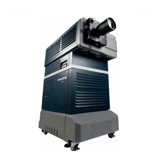
Section 1: Introduction Projector Basics 3.1.1 Components and Features The main CP2000-SB components appear in Figure 3-1 and are briefly described below in alphabetical order. Figure 3-1 Basic Projector and Related Components CP2000-SB User Manual 020-100162-06 Rev. 1 (03-2014) -
Page 48: Air Filter
Each circuit breaker on the pedestal serves two purposes: 1) it is a power switch for one or more components, and 2) it protects against over-current conditions. All breakers must be ON for normal CP2000-SB power-up and operation, enabling AC to reach the CP components If faulty or excessive AC is detected, a breaker will trip to OFF in order to prevent damage to the relevant component. -
Page 49: Coolant Level Gauge
Lamps In the CP2000-SB, use a 2, 3, 4.5 or 6 kilowatt lamp: The lamp door must remain closed and locked for all normal operation. Trained operators (only) can access the lamp via security key. Complete lamp specifications are provided in Section 8.6 Lamps. -
Page 50: Power Cabling
Christie key fob and cannot be duplicated. If you lose or damage a key, contact your dealer or Christie for a new security lock and key set—the keys cannot be replaced individually. NOTE: It is recommended that all keys to the projector be kept in a locked cabinet at the site. -
Page 51: Source/Control Cabling
1. Ensure that the breakers at the main wall panel for the CP are switched ON. 2. At the operator's side of the pedestal, set all CP2000-SB circuit breakers to ON-these are main AC (3-phase), the projection head (2- phase), and terminal block (single-phase). -
Page 52: Power-Down Procedure
2. Wait at least 10 minutes so that fans continue to cool the lamp. Warning! Be sure to wait for the cooling fans! 3. At the operator's side of the pedestal, set all breakers to OFF. NOTE: Manual shut-down only. Optional automation not yet available from Christie. Figure 3-3 Power-down Procedure CP2000-SB User Manual... -
Page 53: Introduction To The Touch Panel Controller
A simple design with familiar menu icons enables a novice user to display an accurate and fully optimized image by pressing a single button on the touch-screen-and precisely configured presentations are protected from accidental or unauthorized change. CP2000-SB User Manual 020-100162-06 Rev. 1 (03-2014) -
Page 54: Tpc Power-Up Defaults
An installer can see ID and error information for servers, as well as a detailed diagnostics log for in-depth troubleshooting. 3.4.2 TPC Power-up Defaults When the CP2000-SB powers up (refer to Section 3.2 Power-up Procedure), the Touch Panel Controller will begin the steps of Initializing…, Attempting to log on…, and Updating status, displaying... -
Page 55: Using The Touch Panel Controller (Tpc)
TPC screen brightness and contrast via the Windows CE Display Settings for this device (service password required). If your TPC is enclosed in a blue casing, use the small knob on the back of the unit to adjust screen settings. 3-10 CP2000-SB User Manual 020-100162-06 Rev. 1 (03-2014) -
Page 56: Tpc Main Menu
START FEATURES or PRESENTATIONS: To start a different feature or presentation, press its correspond- ing display button. STATUS BUTTON: Color indicators, Green = All OK Yellow = Environment/Diagnostics WARNING Red = Environment/Diagnostics CRITICAL ERROR Flashing = ALARM CONDITION CP2000-SB User Manual 3-11 020-100162-06 Rev. 1 (03-2014) -
Page 57: Tpc Status Menu
TPC menus. In addition, a full-screen flashing red alarm window is triggered on the TPC for such problems as failed interlocks (mandatory), over- temperature (optional), and fan problems (optional). 3-12 CP2000-SB User Manual 020-100162-06 Rev. 1 (03-2014) - Page 58 Power ON/OFF Input and Channel Source connection (location) and channel # Signal Hor. and Vert. Freq. of current source Standby ON/OFF (NOTE: lamp remains on regardless) ON/OFF screen display of Cine-IPM menus CP2000-SB User Manual 3-13 020-100162-06 Rev. 1 (03-2014)
- Page 59 SECURITY ENCLOSURE NOTE: If any of the following indicators are “red”, service is needed. Security Enclosure Installed Security Enclosure Armed Security Tamper Component Side Lid Open Non-Component Side Lid Open Enclosure Communication Failure Security Enclosure Battery Low 3-14 CP2000-SB User Manual 020-100162-06 Rev. 1 (03-2014)
- Page 60 Processor Board Diagnostics Performed FPGA Load FPGA Code Valid FPGA Initialize FPGA McBSP XRDY FPGA Done FPGA Register Read/Write Serial ID Chip CLUT SRAM Overlay Framestore SDRAM Resizer FIR Chip Resizer FIFO CP2000-SB User Manual 3-15 020-100162-06 Rev. 1 (03-2014)
-
Page 61: Tpc Alarm Window
Disabling alarm triggers is not recommended for normal operation. Failed interlocks, an SSM communication fault, I C fault, and lamp failures always produce an alarm window-i.e., these alarm triggers cannot be disabled or hidden. 3-16 CP2000-SB User Manual 020-100162-06 Rev. 1 (03-2014) -
Page 62: Responding To An Alarm Window
If interlocks are OK, ensure the 220V connection near Panel C at the rear of the projector head (on the underside) is still plugged in. If lamp re-try still fails, replace the lamp. CP2000-SB User Manual 3-17 020-100162-06 Rev. 1 (03-2014) -
Page 63: Tpc Custom Menu
PCF and 2) the remaining Custom parameters that are not contained in a PCF: the physical location of the input connection (such as a cinema port or DVI port), the screen format, data format, and processing path. 3-18 CP2000-SB User Manual 020-100162-06 Rev. 1 (03-2014) -
Page 64: Custom: Page-1 Menu
Type of gamma correction such aspect ratio and off- as PL2.6. set. Choices defined by installer or administra- tor. Figure 3-9 Custom: Page 1 Menu - Creating Customer PCFs and Other Settings CP2000-SB User Manual 3-19 020-100162-06 Rev. 1 (03-2014) - Page 65 Use of DVI-dual requires a separate adapter at the DVI connectors, and use of DVI- twin requires a special source. Data format settings are not included in a PCF. 3-20 CP2000-SB User Manual 020-100162-06 Rev. 1 (03-2014)
-
Page 66: Custom: Page-2 Menu
Complex Look-up Table. No information available. Pull-Down Sequence Identifies/sets the frame sequence to achieve a target frequency or time relationship with another signal. Pull-Down Offset Identifies/sets the frame offset. SMPTE Field Bit Identifies/sets field offset polarity. CP2000-SB User Manual 3-21 020-100162-06 Rev. 1 (03-2014) -
Page 67: Custom: 3D Control Menu
Output Delay (Time) Offset (in μ) 3D stereo sync output in relation to dark time interval. Positive offset = delay, nega- tive offset = start early. See Output Delay Notes below. 3-22 CP2000-SB User Manual 020-100162-06 Rev. 1 (03-2014) - Page 68 1 complete image. For all 3D use, the bottom value is 2, indicating that two frames-left and right-are combined into every complete display frame. For non-3D, it is 1 frame. Set to the highest rate possible without image cropping. CP2000-SB User Manual 3-23 020-100162-06 Rev. 1 (03-2014)
- Page 69 The Output Delay setting shifts the 3D sync in relation to the Dark Time interval, starting each frame slightly earlier (-) or later (+). Adjust only as necessary-too much offset can cause bleed-through where each eye sees some data that is intended for the other. 3-24 CP2000-SB User Manual 020-100162-06 Rev. 1 (03-2014)
-
Page 70: Custom: Lamp Menu
With the desired light output measured at the screen, press Set to automatically enable LiteLOC The current brightness level will be maintained as long as possible. NOTE: Arbitrary units shown here, not footlamberts or lumens. CP2000-SB User Manual 3-25 020-100162-06 Rev. 1 (03-2014) -
Page 71: Custom: Lens Menu
Use the drop-down menu to select a particular channel and click Copy for the changes to affect the to Channel selected channel. Repeat for every channel that requires the same ILS values. 3-26 CP2000-SB User Manual 020-100162-06 Rev. 1 (03-2014) -
Page 72: Channel: Lens Menu Disabled
Patterns and User-that enable installers, administrators and advanced users to define numerous system operating parameters, load and/or display test patterns, work with lamp settings, and set up users and their TPC access rights. CP2000-SB User Manual 3-27 020-100162-06 Rev. 1 (03-2014) -
Page 73: Advanced: Preference Menu
Set button. Screen Saver Enable/disable a TPC screen saver, and set its start-up delay. NOTE: To use a unique screen saver, a user-defined.bmp must be downloaded to the TPC, replacing the default. 3-28 CP2000-SB User Manual 020-100162-06 Rev. 1 (03-2014) -
Page 74: Advanced: Lamp Menu
Indicates current light output (shown as solid vertical bar) and LiteLOC level set (single horizontal line). Consider the value at the top of the meter as arbitrary-i.e., not representing actual lumens or fL. CP2000-SB User Manual 3-29 020-100162-06 Rev. 1 (03-2014) -
Page 75: Adding A New Lamp
Save button for recording in memory the serial number of a new lamp and the number of hours it has already been in use (if applicable). Figure 3-19 Advanced: Lamp History Menu Options 3-30 CP2000-SB User Manual 020-100162-06 Rev. 1 (03-2014) -
Page 76: Advanced: Lens Menu
This feature is useful for initiating an auto lens reset. Each motor can either be reset individually or select All Axes when prompted to reset the 4 motors in succession. CP2000-SB User Manual 3-31 020-100162-06 Rev. 1 (03-2014) -
Page 77: Advanced: Test Pattern Menu
To change the order in which a test pattern will be projected when cycled with the Test Pattern button, highlight the name (not its checkbox) in the top window and use the arrow keys near the top of the menu to move the pattern higher or lower in the list. 3-32 CP2000-SB User Manual 020-100162-06 Rev. 1 (03-2014) -
Page 78: Advanced: User Menu
User Name box. The current login (user) cannot be deleted. Cancel Escape to the original User Menu without saving changes. Save Record current User Menu settings in TPC memory. CP2000-SB User Manual 3-33 020-100162-06 Rev. 1 (03-2014) - Page 79 2. Enter the desired password 3. Re-enter the new password in the Confirm PW box 4. Press Save WHO IS CURRENTLY LOGGED ON? Enter the User Menu-the User Name displayed is currently logged on. 3-34 CP2000-SB User Manual 020-100162-06 Rev. 1 (03-2014)
-
Page 80: Tpc Admin Menu
Test in display Save settings in a without saving. source file for access in Custom menu. Cancel new (unsaved) source settings. Figure 3-24 Admin: Source Menu Options CP2000-SB User Manual 3-35 020-100162-06 Rev. 1 (03-2014) - Page 81 You may have to experiment with the values to accurately zoom in on a precise area, and you must also define offset (see below) if you want to zoom in on an area other than the center. 3-36 CP2000-SB User Manual 020-100162-06 Rev. 1 (03-2014)
- Page 82 Alternate Content 1 Auto square pixels 1920 x 1080 2.39 (scope) Alternate Content 2 Auto square pixels 1920 x 800 2.40 (scope) 3D Flat Auto square pixels 3D Scope Auto square pixels CP2000-SB User Manual 3-37 020-100162-06 Rev. 1 (03-2014)
-
Page 83: Admin: Screen Menu
Save current presentation, cropping, lens factor and auxiliary factor settings as a Screen file accessed and applied from within the Custom menu. Restore Cancel new (unsaved) screen settings. Test Apply current settings to the image without saving. 3-38 CP2000-SB User Manual 020-100162-06 Rev. 1 (03-2014) - Page 84 To correct a bowed edge so that it appears straight in the display, activate one of the cropping bow points between two corner points and adjust the slidebar or enter the specific x or y value desired. Figure 3-28 Simple Cropping Example CP2000-SB User Manual 3-39 020-100162-06 Rev. 1 (03-2014)
-
Page 85: Admin: Gamut Menu
MCGDs, naming them as desired. To use an MCGD file as the reference file for target color processing (such as with a certain source and/or lens), select it in the Custom menu. 3-40 CP2000-SB User Manual 020-100162-06 Rev. 1 (03-2014) - Page 86 For theatre use, there should be little need to create custom TCGDs, as the pre-defined TCGDs are used instead. See Create TCGD Notes below. CP2000-SB User Manual 3-41 020-100162-06 Rev. 1 (03-2014)
- Page 87 MCGD file with a different file name. Each setup (channel) can then use any desired MCGD file as the basis for the color corrections needed for a target color. MCGD files are chosen in the Custom menu. NOTE: Once created, user-created MCGD files can be deleted only by using Christie's licensed DCP Librarian software.
- Page 88 If you have already saved a new OnSite file (by pressing the Create MCGD button), the old OnSite file cannot be restored. To Restore a TCGD File: Select the Restore button any time before saving. CP2000-SB User Manual 3-43 020-100162-06 Rev. 1 (03-2014)
-
Page 89: Admin: Ip Config Menu
Choose which Enables/disables MIB structure to SNMP retrieve Trap configuration. Object ID from (default=11273). Enter specific address to send trap information. Figure 3-33 Choosing SNMP from Admin: IP Config Menu 3-44 CP2000-SB User Manual 020-100162-06 Rev. 1 (03-2014) - Page 90 Consult the site's network administrator to determine the necessary settings for compatibility with the local network, then use the TPC to define these new settings in the projection head. NOTES: 1) Password- protected; requires a Christie installer login. 2)Projector can be on the network during these changes, if desired.
- Page 91 NOTE: This is the simplified explanation of valid addressing. A trained network administrator may expand the range of valid addresses. To implement the address changes in your projector and TPC, re-boot. Important! Do not forget to re-boot the projector. 3-46 CP2000-SB User Manual 020-100162-06 Rev. 1 (03-2014)
-
Page 92: Admin: General And Admin: Lamp Menus
TPC responses. Note that when the memory card becomes full, logging continues and simply writes over the oldest entries. Error Message When enabled, an error message will be sent via Ethernet whenever an alarm condition is encountered. Enabled CP2000-SB User Manual 3-47 020-100162-06 Rev. 1 (03-2014) -
Page 93: Admin: Gpio Menu
LENS STATE and SYSTEM HEALTH STATUS. NOTES: 1) Only GPIO 1-5 can be programmed. 2) Use of GPIO for 3D will automatically un-program any other use for that pin. GPI macro name. Predefined macro. GPO Macro name. Predefined macro. Figure 3-37 Admin: GPIO Menu Options 3-48 CP2000-SB User Manual 020-100162-06 Rev. 1 (03-2014) -
Page 94: Tpc About Menu
Consult the About menu to determine the current level of a hardware or software component installed in your projector. Upgrading any of these components requires a Christie service technician. TOUCH PANEL - Determines the software functionality of the Touch Panel Controller (TPC), its menu language, and its operating system. -
Page 95: Selecting A Display (Starting A Presentation)
For any display button on the two-page Main menu, the projector interprets incoming signal data according to one of sixteen user-selectable display setups defined at the time of CP2000-SB installation (and/or with each subsequent release of a new digital cinema feature) and stored in projector memory. Each display setup consists of Projector Configuration File (PCF) information as well as additional processing, display parameters and screen settings optimized for a particular cinema feature or alternative content source. -
Page 96: Cinema Vs. Non-Cinema Sources
• FAN SPEEDS-caused when a main intake fan, card cage fan, or the laminar air flow device fan fails or is too slow. • LAMP EXPIRY-appears when lamp has reached the end of its life (as defined in the Lamp Limit setting). Important! For normal operation, do not disable alarm triggers. CP2000-SB User Manual 3-51 020-100162-06 Rev. 1 (03-2014) -
Page 97: Remote Control Of The Touch Panel Controller
(?) appears directly after the function code. If the projector is replying, an exclamation mark (!)appears directly after the function code. For set messages, neither of these characters appear-the code is followed by the data itself (see next paragraph). 3-52 CP2000-SB User Manual 020-100162-06 Rev. 1 (03-2014) -
Page 98: Sample Messages And Their Meaning
Request by controller for picture mute status Picture mute reply from proj. (PMT!000) Reply from proj. that picture is mute is off. Set picture mute (PMT 1) Turn the picture mute on (blank the image) CP2000-SB User Manual 3-53 020-100162-06 Rev. 1 (03-2014) -
Page 99: What Is Actually Sent In A Message
Important! To prevent shutdown of the socket, program the controller to send a PNG? every 5-10 min- utes. SHUTDOWN Warning! You must close the application and shut down the socket properly before shutting down the control- ler. 3-54 CP2000-SB User Manual 020-100162-06 Rev. 1 (03-2014) -
Page 100: Upgrading Ssm Firmware
You will use an FTP program to transfer the new version file from your PC to the TPC currently connected to your CP2000-SB projector. 3.7.1 Requirements • TPC-642 or TPC-60 or TPC-66 used with any CP2000-SB projector. • Windows™ 2000 or XP running on a laptop or PC. • Correct SSM Firmware version •... -
Page 101: Troubleshooting
• If FFFTP still fails to download files properly, re-boot the Figure 3-44 Host Setting-Advanced Tab TPC by disconnecting then re-connecting it. • If FFFTP still fails to download files properly, try the WS_FTP or similar program. 3-56 CP2000-SB User Manual 020-100162-06 Rev. 1 (03-2014) -
Page 102: Working With The Lamp
If the lamp fails to ignite, the projector will automatically re-try ignition using 100% of the maximum power acceptable for the lamp. If this re-try also fails, and there is no interlock problem such as an open lamp door, a new lamp is likely needed. CP2000-SB User Manual 3-57 020-100162-06 Rev. 1 (03-2014) -
Page 103: Adjusting Lamp Power (Liteloc™ Or Manually)
If desired, reset LiteLOC™ to a different level at any time, or override with a specific lamp power setting. 3-58 CP2000-SB User Manual 020-100162-06 Rev. 1 (03-2014) -
Page 104: Using Lamp Power
LiteLOC™ setting, the recovery will be immediate. When re-enabling LiteLOC™ from a brightness setting that differs by only 10% or less, the recovery will be gradual. Adjust. LiteLOC™ no longer in effect. Meter tracks with adjustment. Figure 3-48 Using a Specific Power Level CP2000-SB User Manual 3-59 020-100162-06 Rev. 1 (03-2014) - Page 105 CXL/CDXL-45 (4.5) 95-155 CXL/CDXL-60 (6.0) 105-165 CDXL-60SD (6.0) 105-170 * CXL-20 requires adaptor kit (P/N 003-001728-XX). NOTE: A Lamp Power setting of 110 will exceed the maximum values shown here by approx. 10%. 3-60 CP2000-SB User Manual 020-100162-06 Rev. 1 (03-2014)
-
Page 106: Adjusting Lamp Position For Lamploc
5. Repeat Steps 1-4, but reading at the screen instead Steps 1 of at the lens. and 3 6. Reset Lamp Power or LiteLOC™ if desired. Figure 3-50 Adjusting Using a Light Meter CP2000-SB User Manual 3-61 020-100162-06 Rev. 1 (03-2014) -
Page 107: Stand-By Mode
The Status menu also shows Total Lamp Hours, which is the accumulated time logged for all lamps installed thus far. Each past lamp log also appears in the Advanced: Lamp History menu. Figure 3-52 Lamp Hours 3-62 CP2000-SB User Manual 020-100162-06 Rev. 1 (03-2014) -
Page 108: When To Replace The Lamp
Over time, as the theatre screen ages and dust and dirt collects on the port window, the theatre may no longer be achieving the expected footlamberts as reported by the TPC. It is a good idea to periodically recalibrate footlamberts (refer back to Figure 3-36). CP2000-SB User Manual 3-63 020-100162-06 Rev. 1 (03-2014) -
Page 109: Working With The Lens
Section 1: Introduction Working with the Lens The CP2000-SB lens mount secures the primary zoom lens to the projection head. It provides 1) setup adjustments for correct boresight, and 2) automatically controlled focus, zoom and offsets for general use. To... -
Page 110: Offsets
This lens increases magnification across the width only, regaining the original proportions in the image, and is often used in theatres where side masking can be moved aside. CP2000-SB User Manual 3-65 020-100162-06 Rev. 1 (03-2014) -
Page 111: Working With 3D
3.10.2 What Do I Need for 3D? The CP2000-SB requires a 3D-capable SMPTE source and a few special hardware/software setups described here. Essentially you will connect two signals (one left eye, one right eye) to the projector, then use the TPC's Custom: 3D Control menu options to define and control the signal processing, synchronizing and output for devices used in your stereographic 3D display. -
Page 112: Supported Hardware Setup
2) A pull-up power supply (not shown) is also required for the IR emitter or polarizing cell. 3) See The GPIO Port, on page D-2 for cabling details. Figure 3-56 Typical Dual-Input 3D System (CP2000 Shown with Active Glasses) CP2000-SB User Manual 3-67 020-100162-06 Rev. 1 (03-2014) -
Page 113: Other Hardware Setups
3.10.4 Other Hardware Setups Other expected hardware configurations with a single 3D source input are shown in Figure 3-57. NOTE: For future reference. Single 3D input is not currently supported. Figure 3-57 Single-Input 3D Systems 3-68 CP2000-SB User Manual 020-100162-06 Rev. 1 (03-2014) -
Page 114: Instructions
An incorrect setting creates motion artifacts. 5. DEFINE SYNC DISPLAY LOCATION: • Set L/R Display Reference to Not Used. • Set Display GPI to None. CP2000-SB User Manual 3-69 020-100162-06 Rev. 1 (03-2014) -
Page 115: Troubleshooting
If the image seems to jump back and forth during horizontal pans, the L/R Display Sequence is likely backwards. Try reversing the current setting. Single 3D Input Does Not Work A single source signal containing both left and right data is not currently supported. 3-70 CP2000-SB User Manual 020-100162-06 Rev. 1 (03-2014) -
Page 116: Working With Servers And Diagnostics
Update test (.xml). results. (Similar to refresh). Or Test results - see if subtitling is May show errors running. in .xml content and/or transmission from server. Figure 3-60 Status: Server Menu Options CP2000-SB User Manual 3-71 020-100162-06 Rev. 1 (03-2014) -
Page 117: Tpc Status: Diag Menu
Interrogator during a show as this could cause image Figure 3-62 Status: Interrogator Menu Options disruption. 3) Interrogator is also accessible through a separate login and password (different from the service login). Contact Christie tech support for assistance and password. 3-72 CP2000-SB User Manual 020-100162-06 Rev. -
Page 118: Cinema Operation
Section 2 Installation & Setup. Read also Section 3 Operation. • 4.1 Compatible Cinema Sources • 4.2 Image Formats • 4.3 Selecting the Cinema Source • 4.4 Adjusting the Cinema Display CP2000-SB User Manual 020-100162-06 Rev. 1 (03-2014) -
Page 119: Compatible Cinema Sources
Ensure a digital media storage device or cinema server is connected to one of the A or B input ports within the CP2000-SB head-see Figure 4-1. These connections are typically made at the time of projector installation. Figure 4-1 Cinema Source Connections (External Source Shown) The identical A or B cinema ports use the SMPTE 292M bit-serial interface standard, and will auto-detect cinema source formats shown in Table 4.1. - Page 120 Keep in mind that the projector will attempt to automatically adapt to any incoming data format that does not exceed either the bandwidth of the system or the frame rate limitations, thus formats beyond those shown above may be compatible. CP2000-SB User Manual 020-100162-06 Rev. 1 (03-2014)
-
Page 121: Image Formats
The incoming material will then be squeezed into a narrower area on the projector's DMD panels, with the final aspect ratio setting determining the actual degree of compression. Refer to Section 3.5 Using the Touch Panel Controller (TPC) for more information about choosing Source menu settings. CP2000-SB User Manual 020-100162-06 Rev. 1 (03-2014) -
Page 122: Theatre Variables: Masking
In some cases, a theatre has both side and top/bottom masking installed. This arrangement is the most flexible of all. Figure 4-5 Side Masking for Flat Refer to Table 4.2 for a summary of the basic factors affecting cinema displays in a variety of theatres. CP2000-SB User Manual 020-100162-06 Rev. 1 (03-2014) - Page 123 Section 1: Introduction Table 4.2 Basic Ways to Achieve Flat & Scope Displays CP2000-SB User Manual 020-100162-06 Rev. 1 (03-2014)
-
Page 124: Selecting The Cinema Source
CP2000-SB installer, administrator or trained operator, this simplicity ensures that the intended display can be selected quickly and easily by any user. -
Page 125: Other Methods
If you feel the cinema display is incorrect or faulty, contact the trained operator in your theatre who can correct or further customize specific display file settings. CP2000-SB User Manual 020-100162-06 Rev. 1 (03-2014) -
Page 126: Non-Cinema Operation
This section explains how to display alternative content originating from a standard definition or high definition non-cinema source such as a PC or other graphics devices. Such a source routes to a DVI (Digital Visual Interface) port in the CP2000-SB projection head, and can bypass cinema processing when necessary. -
Page 127: Compatible Non-Cinema Sources
Section 1: Introduction Compatible Non-Cinema Sources Ensure your non-cinema DVI source is connected to DVI-1 or DVI-2 within the CP2000-SB head-see Figure 5-1. These connections are typically made at the time of projector installation. Figure 5-1 Non-Cinema DVI Source Connection (shown with external source) Each DVI port accepts and will auto-detect the progressive-scan, digital RGB sources listed in Table 5.1,... -
Page 128: Dual- And Twin-Link Dvi
NOTES: 1) Neither the Christie dual-link adapter nor the proposed 3rd-party twin-link source (and cables) shown here are currently available. 2) Using both DVI ports with the Christie Cine-IPM 2K enables 10-bit output and displays. Consult the Cine-IPM 2K User Manual for details. -
Page 129: Selecting The Source
At the Main menu of the Touch Panel Controller, select one of the cinema display buttons pre-configured for a cinema source input at port A or B -the CP2000-SB will now ignore the DVI ports and respond to the cinema source activated by this button. -
Page 130: Maintenance
Maintenance This section describes methods for safely maintaining the CP2000-SB projector. NOTE: The illustrations provided are to enhance the understanding of the written material. They are graphical representations only and may not represent your exact projector model. • 6.1 Warnings and Guidelines •... -
Page 131: Warnings And Guidelines
6.1.2 General Precautions Be aware of the following general precautions in all CP2000-SB installations: 1) Never look directly into the projector lens or at the lamp. The extremely high brightness can cause permanent eye damage. 2) For protection from ultraviolet radiation, keep all projector housings intact during operation. -
Page 132: Ac/Power Precautions
Disconnect at BOTH wall breakers. 6.1.4 Lamp Precautions Any Xenon arc lamp used in the CP2000-SB is under high pressure and must be handled with great care at all times. Lamps may explode if dropped or mishandled. -
Page 133: Maintaining Proper Cooling
The LAD should be nearly white or light gray in color. 6.2.3 Liquid Cooler The liquid cooler system circulates liquid to and from the DMDs in the CP2000-SB projection head, reducing their operating temperature to an acceptable level. Periodically check the coolant level visible through the gauge/window on the non-operator's side of the pedestal, and make sure that it remains between the two notches (preferably closer to the top notch). -
Page 134: Exhaust Duct & Lamp Fan Interlocks
Inspect the mirror surface (reflector) for cleanliness only during a lamp replacement, when the lamp is out. If necessary, clean as described below-ensure to wear protective clothing while inspecting or cleaning. Note that color on the reflector surface may vary-this is normal. CP2000-SB User Manual 020-100162-06 Rev. 1 (03-2014) -
Page 135: Supplies
2. Fold a clean microfibre cloth and dampen with methanol. Make sure to wipe evenly with the smooth portion of the cloth that has no folds or creases. Do not apply pressure with your fingers-use the solution in the cloth to collect the dirt. CP2000-SB User Manual 020-100162-06 Rev. 1 (03-2014) -
Page 136: Other Components
Inspect regularly and confirm that 1) there are no obstructions or kinks within the ducting, 2) all air intake areas of the CP2000-SB are unobstructed, and 3) exhaust airflow is within the range shown in Table 2.1 on page 11. Ensure lamp wiring does not interfere with vane switch. -
Page 137: Lamp Replacement Procedure
Specifications-never install a lamp intended for a different model or projector. Warning! 1) Make sure to use the correct wattage lamp supplied by Christie. 2) Lamp replacement is to be done by a qualified service technician only. 3) EXPLOSION HAZARD - Wear authorized protective clothing whenever the lamp door is open! Never apply a twisting or bending force to the quartz lamp body. - Page 138 If you accidentally touch the quartz body of the lamp with your bare hands, clean it as described in Section 6.3 Maintenance and Cleaning. Figure 6-2 Secure bulb at cathode (-) and anode (+) connectors CP2000-SB User Manual 020-100162-06 Rev. 1 (03-2014)
- Page 139 Section 3.8.4 Adjusting Lamp Position for LampLOC™. This ensures maximum performance, with the lamp (bulb) well-centered with the reflector and distanced correctly from the rest of the illumination system. 6-10 CP2000-SB User Manual 020-100162-06 Rev. 1 (03-2014)
-
Page 140: Filter Replacement Procedure
Slide the filter up and discard. Insert the new air filter, following the labeling for proper inside/outside ori- entation. Slide all the way down into its slot (3. and 4. in Figure 6-3). Warning! Use only Christie filters. Never operate the projector without the filter installed. -
Page 141: Replacing A Lens
2. Pull out lens and replace with a different primary lens as described in Section 2.1.4 Lens(es). 3. Secure with lens locking lever (down position). 4. Calibrate the lens. See Section 2.7 Basic Image Alignment for details. 6-12 CP2000-SB User Manual 020-100162-06 Rev. 1 (03-2014) -
Page 142: Troubleshooting
NOTE: A qualified service technician is required when opening an enclosure to diagnose any probable cause. • 7.1 Power • 7.2 Lamp • 7.3 TPC • 7.4 Ethernet • 7.5 Cinema Displays • 7.6 Non-Cinema Displays CP2000-SB User Manual 020-100162-06 Rev. 1 (03-2014) -
Page 143: Power
6. If there is no buzzing indicating that the igniter is attempting ignition, there may be a problem with the igniter (Christie service required). 7. If there is a brief buzz attempting ignition but a lamp does not ignite, the lamp likely needs to be replaced. -
Page 144: Flicker, Shadows Or Dimness
CompactFlash memory card. Save backups to a PC/laptop only, not the TPC (contact your administra- tor). 6. If the locations of button presses on the screen seem to be misinterpreted, the TPC screen may need recalibrating. CP2000-SB User Manual 020-100162-06 Rev. 1 (03-2014) -
Page 145: Ethernet
The display file needs correction. 7.5.3 Image Appears Squeezed or Vertically Stretched into Center of Screen Source data converted from film and pre-squeezed for CP2000-SB's display format may require use of the anamorphic lens to regain full scope image width and proper proportions. -
Page 146: Non-Cinema Displays
2. Sizing and positioning options may be adjusted poorly for the incoming source signal. 3. Use an anamorphic lens for typical HDTV and anamorphic DVD sources that have been re-sized and vertically stretched via 3rd-party software. CP2000-SB User Manual 020-100162-06 Rev. 1 (03-2014) -
Page 147: Data Is Cropped From Edges
NOTE: password-protected. 2. Or, if you do not have access to the Touch Panel Controller's Advanced menu and cannot adjust the processing path, use your 3rd-party input source to crop off the streaks. CP2000-SB User Manual 020-100162-06 Rev. 1 (03-2014) -
Page 148: Specifications
• 8.2 Lenses • 8.3 Inputs • 8.4 Touch Panel Controller • 8.5 Power Specifications • 8.6 Lamps • 8.7 Regulatory • 8.8 Environment • 8.9 Weight & Size • 8.10 Standard Components CP2000-SB User Manual 020-100162-06 Rev. 1 (03-2014) -
Page 149: Display
100% (vertical), 70% (horizontal) 2.2 - 3.0:1 108-277101-01 100% (vertical), 70% (horizontal) 3.0 - 4.3:1 108-278101-01 100% (vertical), 70% (horizontal) 4.3 - 6.0:1 108-279101-01 100% (vertical), 70% (horizontal) 5.5 - 8.5:1 108-280101-01 100% (vertical), 70% (horizontal) CP2000-SB User Manual 020-100162-06 Rev. 1 (03-2014) -
Page 150: Inputs
NOTE: Currently supported DVI formats (i.e., non-cinema formats) are listed in Table 5.1 on page 2. 8.3.3 Control Ports RS-232 connectors (2): 9-pin D female A= Non-ASCII PC communication B=Christie-propri- etary accessories only Ethernet connector (1): RJ-45 female Stnd. 100 base-TX, 100 Mbps max. -
Page 151: Touch Panel Controller
Max. power consumption 230 W Max. current at this AC input Lamp DC Max. voltage 41 VDC Start-up voltage 80 V min., 107 V max. Max. current consumption 170 A Max. power consumption 6600 W CP2000-SB User Manual 020-100162-06 Rev. 1 (03-2014) -
Page 152: Lamps
Section 1: Introduction CP2000-SB Pedestal (3-Phase Plus Single-Phase) Nominal voltage 208 VAC (N. America / Japan) 400 VAC (Europe / Asia) Absolute operating voltage range 180-235 VAC (N. America / Japan) 342-456 VAC (Europe / Asia) Line frequency 50 Hz - 60 Hz nominal Inrush current (max.) NOTE: does not include lamp... -
Page 153: Regulatory
• FCC CFR47, Part 15, Subpart B, Class A - Unintentional Radiation • CISPR 22: 2003 +A1:2004 / EN55022: 1998 +A2:2003, Class A - Information Technology Equipment EMC Immunity CISPR 24:1997 / EN55024:1998 +A1:2001 +A2:2003 EMC Requirements - Information Technology Equipment CP2000-SB User Manual 020-100162-06 Rev. 1 (03-2014) -
Page 154: Environment
25" (63.5 cm) x 55.5" (141 cm) x 54" (137.2 cm) (with longest primary lens, no anamorph) Size with Anamorph (W x L x H) 25" (63.5 cm) x 62" (157.5 cm) x 54" (137.2 cm) (with auxiliary lens mount & lens) CP2000-SB User Manual 020-100162-06 Rev. 1 (03-2014) - Page 155 Section 1: Introduction CP2000-SB User Manual 020-100162-06 Rev. 1 (03-2014)
-
Page 156: Standard Components
• Assorted cabling (most pre-connected) and misc. assembly hardware • CP2000-SB User Manual Other Protective Clothing Kit (for opening of lamp door) 598900-095 DCP Librarian Setup Software (for calibration / setup by Christie installer) CP2000-SB User Manual 020-100162-06 Rev. 1 (03-2014) - Page 157 Section 1: Introduction 8-10 CP2000-SB User Manual 020-100162-06 Rev. 1 (03-2014)
-
Page 158: A Appendix A: Glossary
Appendix A: Glossary The glossary defines the specific terms used in this manual as they apply to this projector. Also included are other general terms commonly used in the projection industry. CP2000-SB User Manual 020-100162-06 Rev. 1 (03-2014) - Page 159 The ratio of the width of an image to its height, such as the 4:3 aspect ratio common in video output. Can also be expressed as a decimal number, such as 1.77, 1.85 or 2.39. The larger the ratio or decimal, the wider and less square the image. CP2000-SB User Manual 020-100162-06 Rev. 1 (03-2014)
- Page 160 • lighting level in the auditorium • non-sync play and fade in/out • digital cinema projector NOTE: Christie’s optional automation system is not yet available. AUTO SOURCE The ability of the projector to automatically recognize and synchronize to the horizontal and vertical scan frequencies of an input signal for proper display.
- Page 161 COLOR TEMPERATURE The coloration (reddish, white, bluish, greenish, etc.) of white in an image, measured using the Kelvin (degrees K) temperature scale. Higher temperatures output more light. COMPONENT VIDEO Refer to YcbCr or YPbPr. CP2000-SB User Manual 020-100162-06 Rev. 1 (03-2014)
- Page 162 CONVERGENCE The alignment of the red, green, and blue light elements of a projected image so that they appear as a single element. In this projector, convergence can be adjusted by Christie service personnel only. CURVED SCREEN A projection screen which is slightly concave for improved screen gain. Curved screens usually have screen gains, which are greater than 1 but viewing angles much less than 180°.
- Page 163 For example: An image reflecting off a 10 gain screen appears 10 times brighter than it would if reflected off a matte white wall. Curved screens usually have larger gain than flat screens. CP2000-SB User Manual 020-100162-06 Rev. 1 (03-2014)
- Page 164 ILS™ The Intelligent Lens System describes the ability of Christie projectors having a motorized lens mount to ™ automatically return to lens settings previously defined for a particular channel. Not available in cinema projectors such as CP2000.
- Page 165 “keyhole” shaped image. It is caused when the lens surface is not parallel to the screen. LAMPLOC™ A Christie software feature where samples of output light from a projector guide the precise position of the lamp along 3 axes—vertical, horizontal and distance to lens—so that lamp performance and output is maximized. LIFE SAFETY A safety control system integrated into the HVAC, fire alarm, and other infrastructure components of the theatre as well as the presentation system.
- Page 166 A type of rear-projection screen which re-directs light through the screen to increase image brightness in front of the screen. Screen gain is usually greater than 1 but audience viewing angles are reduced. Rarely used in cinema applications. CP2000-SB User Manual 020-100162-06 Rev. 1 (03-2014)
- Page 167 Post production culminates in acceptance of the original negative answer print. Even though post production officially begins on the last day of principal photography, post production facilities such as editing are utilized from very early in the production phase in order to save time. A-10 CP2000-SB User Manual 020-100162-06 Rev. 1 (03-2014)
- Page 168 1024 (called SXGA) or 2048 x 1080. RETRACE TIME (HORIZONTAL) The minimum time required for a CRT projector to move the position of the scanning spot from the right edge to the left edge. CP2000-SB User Manual A-11 020-100162-06 Rev. 1 (03-2014)
- Page 169 IP network. SNMP enables network administrators to manage network performance, find and solve network problems, and plan for network growth. SOURCE The device (such as a server) connected to the projector for supplying incoming data. SOURCE SETUP Refer to Channel. A-12 CP2000-SB User Manual 020-100162-06 Rev. 1 (03-2014)
- Page 170 THROW DISTANCE The distance between the front feet of the projector and the screen. Also called Projector-to-Screen Distance. Always use the correct Christie throw distance formula to calculate the proper throw distance (±5%) required for your lens. THROW RATIO Throw ratio = throw distance / screen width.
- Page 171 Data embedded in essence that serve different purposes and that are either imperceptible or obvious, robust or fragile. Their usual purpose is for legal support of copyright, and they may also be components of copy control schemes. WHITE BALANCE The color temperature of white used by the projector. A-14 CP2000-SB User Manual 020-100162-06 Rev. 1 (03-2014)
- Page 172 A high-end analog component video signal. Sometimes called YUV, Component, or Y, R-Y, B-Y, the YPbPr signal by- passes the video decoder in this projector. See YPbPr. ZOOM The adjustment of image size by means of a zoom lens. CP2000-SB User Manual A-15 020-100162-06 Rev. 1 (03-2014)
- Page 173 Section 1: Introduction A-16 CP2000-SB User Manual 020-100162-06 Rev. 1 (03-2014)
-
Page 174: B Appendix B: Ascii Messages
NOTE: Please refer to Section 3.6 Remote Control of the Touch Panel Controller for a complete explanation of remote communications setup, message protocol and format. • B.1 Function Codes • B.2 Messages with Multiple Parameters CP2000-SB User Manual 020-100162-06 Rev. 1 (03-2014) -
Page 175: B.1 Function Codes
Range = 101-132 Color Space Selection (CSP) (CSP “P7v2”) Set the color space (gamut, or TCGD) to P7v2 (CSP?) What color space is currently in use? (CSP!“P7v2”) The P7v2 color space is currently in use CP2000-SB User Manual 020-100162-06 Rev. 1 (03-2014) - Page 176 1 = Standard logging (errors plus select operations) (DLG!002) 2 = All activities are logged Error Message Enable (EME) (EME 1) Enable error messages sent via Ethernet, where (EME!001) 0= disabled and 1= enabled. Refer to ERR. CP2000-SB User Manual 020-100162-06 Rev. 1 (03-2014)
- Page 177 48 = SSM, Upgrade Failed 68 = I2C Communication Error 96 = ILS, Communications Error 97 = ILS, Sensor Failure 98 = ILS, In Bootloader 99 = ILS, CRC failure on main code CP2000-SB User Manual 020-100162-06 Rev. 1 (03-2014)
- Page 178 See Messages With Multiple Parameters in this Appendix. Gamma (GAM) (GAM!”gamma2.6”) The “filename” representing the current gamma. For example, “gamma2.6” is typically used in theatres. Gamma files (name and content) are all currently pre-defined. Also known as “look-up tables”. CP2000-SB User Manual 020-100162-06 Rev. 1 (03-2014)
- Page 179 Method of reading and writing ILS information. See Section B.2.4 Intelligent Lens System (ILS) Internal Test Pattern (ITP) (ITP “RGB-12Bbit-Split Ramp”) Enter “test pattern filename” to display pattern. (ITP””) Enter “” to turn off the test pattern. CP2000-SB User Manual 020-100162-06 Rev. 1 (03-2014)
- Page 180 “Lamp Per Channel” checkbox is enabled, and to all channels when the checkbox is cleared. (LPI?) What is the current LiteLOC setting for this channel? (LPI?s101) What is the LiteLOC setting for Channel 101? (LP1!12345) The current LiteLOC setting is 12345 CP2000-SB User Manual 020-100162-06 Rev. 1 (03-2014)
- Page 181 1 = On; Lamp settings will vary according to channel. (LPB! 1) NOTE: This setting determines whether lamp mode, power and intensity are the SAME for every channel (i.e., global) or DIFFERENT for each. CP2000-SB User Manual 020-100162-06 Rev. 1 (03-2014)
- Page 182 P1 = Real-time position P2 = Current direction P3 = Moving Status (0 = not moving, 1 = moving) Related commands are Intelligent Lens System (ILS), Lens Vertical Offset (LVO), Focus (FCS) and Zoom (ZOM) CP2000-SB User Manual 020-100162-06 Rev. 1 (03-2014)
- Page 183 (PNG! 032 001 002) Reply indicating cinema projector present (32), and its current version of software is v1.2 P1 = 32 (always—indicates a cinema projector) P2 = Major version 0-99 P3 = Minor version 0-99 B-10 CP2000-SB User Manual 020-100162-06 Rev. 1 (03-2014)
- Page 184 1= field offset to 2 2 = field offset to 3 3 = field offset to 4 4 = field offset to 5 (PDO?) Request field offset (PDO! 002) Response indicating field 3 offset CP2000-SB User Manual B-11 020-100162-06 Rev. 1 (03-2014)
- Page 185 16). To change the input on a different channel, the source number must be used in front of the parameter that is used. (SIN s1 1) changes channel one input to 292B. B-12 CP2000-SB User Manual 020-100162-06 Rev. 1 (03-2014)
- Page 186 (TMD! 2003 08 13 14 21 00) P1 = Year (yyyy) P2 = Month (01-12) P3 = Date (1-31, day of month) P4 = Hour (0-23, 24hr clock) P5 = Minute (0-59) P6 = Second (0-59) CP2000-SB User Manual B-13 020-100162-06 Rev. 1 (03-2014)
- Page 187 (LPL?M) What is the minimum and maximum lamp limit? (LPL!M000 5000)Minimum lamp limit = 0, maximum lamp limit = 5000 If a function code has multiple parameters (see B.2 Messages with Multiple Parameters), their ranges cannot be requested. B-14 CP2000-SB User Manual 020-100162-06 Rev. 1 (03-2014)
-
Page 188: Error Messages (Err
See Table B.3, Table B.4, and Table B.5. When a system error is resolved and is no longer present, another message reports this by replacing the first digit in the original P3 error code with a "1". CP2000-SB User Manual B-15 020-100162-06 Rev. 1 (03-2014) - Page 189 Card Cage Over temperature Ballast Over temperature Lamp Life Expired Lamp Failed to Strike Unexpected Lamp Failure / Off Reading Lamp Intensity Failed SSM, Communication Failure (System Supervisor Module) SSM, Upgrade Failed C Communication Failure B-16 CP2000-SB User Manual 020-100162-06 Rev. 1 (03-2014)
-
Page 190: Examples Of Critical System Error (001) Messages
(65535 01002 ERR 002 "System Warning: 8010 00051 Prism, Temperature Warning") (65535 01002 ERR 002 "System Warning: 8020 00001 Lamp, Life Expired") (65535 01002 ERR 002 "System Warning: 8032 00001 SSM Read Failed") CP2000-SB User Manual B-17 020-100162-06 Rev. 1 (03-2014) -
Page 191: For Your Information (Fyi
Offset), FCS (Focus), and ZOM (Zoom). NOTE: Approach is optional. When no approach is specified, a Negative to Positive Approach is assumed. -1 = Positive to Negative Approach 1 = Negative to Positive Approach B-18 CP2000-SB User Manual 020-100162-06 Rev. 1 (03-2014) -
Page 192: Examples Of Ils Commands
8 = Processor Board Serial # 9 = Processor Board Type 10 = Interface Board Type 11 = Formatter Interface Type 12 = Formatter Board Type 13 = TPC Type 14 = ILS Board Serial Number CP2000-SB User Manual B-19 020-100162-06 Rev. 1 (03-2014) - Page 193 40 = SmpteATotalErr 41 = SmpteARecentErr 42 = SmpteBTotalErr 43 = SmpteBRecentErr 50 = SecurityInstalled 51 = SecurityArmed 52 = SecurityTamper 53 = CompLidOpen 54 = NonCompLidOpen 55 = CommFailure 56 = BatteryLow B-20 CP2000-SB User Manual 020-100162-06 Rev. 1 (03-2014)
- Page 194 53 = Formatter Green (Gamma) 54 = Formatter Green (Sequence) 60 = Formatter Blue (Boot) 61 = Formatter Blue (Main) 62 = Formatter Blue (Config) 63 = Formatter Blue (Gamma) 64 = Formatter Blue (Sequence) CP2000-SB User Manual B-21 020-100162-06 Rev. 1 (03-2014)
-
Page 195: Controls (Tdc
3 = Left on Port B, Right on Port A 4 = White Line Code (true polarity) 5 = White Line Code (inverted polarity) 6 = Blue Line Code (true polarity) 7 = Blue Line Code (inverted polarity) B-22 CP2000-SB User Manual 020-100162-06 Rev. 1 (03-2014) - Page 196 1 = Inverted 9 = L/R Output Reference GPO 0 = None 1 - 7 = GPO1-GPO7 10 = Dark Time 0 - 4500 μs 11 = Output Sync Delay 0 - 200 μs CP2000-SB User Manual B-23 020-100162-06 Rev. 1 (03-2014)
- Page 197 Section 1: Introduction B-24 CP2000-SB User Manual 020-100162-06 Rev. 1 (03-2014)
-
Page 198: C Appendix C: Serial Communication
Appendix C: Serial Communication This section explains how to link the projector to serial communication devices. • C.1 Serial Links to Projector CP2000-SB User Manual 020-100162-06 Rev. 1 (03-2014) -
Page 199: Standard Rs-232 Devices
Note that a serial link is adequate for DCP Librarian use, or for downloading new main software (both tasks require a qualified Christie service technician). It cannot be used for ASCII messaging (since the TPC recognizes Ethernet only), and is too slow for servers. -
Page 200: D Appendix D: Gpio System Lntegration
Appendix D: GPIO System Integration This section explains how to use a GPIO link from the projector to external equipment such as devices for 3D synchronizing. CP2000-SB User Manual 020-100162-06 Rev. 1 (03-2014) -
Page 201: The Gpio Port
3. In the TPC’s Custom 3D Control menu, set Output GPO according to the pins wired in the GPIO cable (see Figure D-1). For instance, if you have wired pins #10 (+) and #29 (-) to your 3D device, set Output GPO to GPO #2. CP2000-SB User Manual 020-100162-06 Rev. 1 (03-2014) - Page 202 Appendix E: Repacking the Projector If you need to relocate or ship the projector, repack the pedestal and the projection head with the original packing materials used for shipping. CP2000-SB User Manual 020-100162-06 Rev. 1 (03-2014)
- Page 203 Section 1: Introduction Figure E-1 Packing the Pedestal and Projection Head CP2000-SB User Manual 020-100162-06 Rev. 1 (03-2014)
Need help?
Do you have a question about the CP2000-SB and is the answer not in the manual?
Questions and answers