Table of Contents
Advertisement
Advertisement
Table of Contents
Troubleshooting

Related Manuals for Thermo Scientific Accela Open Autosampler


Summary of Contents for Thermo Scientific Accela Open Autosampler
- Page 1 Accela Open Autosampler Hardware Manual 60357-97102 Revision D December 2013...
- Page 2 © 2013 Thermo Fisher Scientific Inc. All rights reserved. EQuan, QuickQuan, TSQ Vantage, and Velos are trademarks, and Accela, Exactive, TSQ Quantum, and Xcalibur are registered trademarks of Thermo Fisher Scientific Inc. in the United States. The following are registered trademarks in the United States and other countries: Agilent is a registered trademark of Agilent Technologies Inc.
- Page 3 Regulatory Compliance Thermo Fisher Scientific performs complete testing and evaluation of its products to ensure full compliance with applicable domestic and international regulations. When the system is delivered to you, it meets all pertinent electromagnetic compatibility (EMC) and safety standards as described in the next section or sections by product name. Changes that you make to your system may void compliance with one or more of these EMC and safety standards.
- Page 4 Notice on Lifting and Handling of Thermo Scientific Instruments For your safety, and in compliance with international regulations, the physical handling of this Thermo Fisher Scientific instrument requires a team effort to lift and/or move the instrument. This instrument is too heavy and/or bulky for one person alone to handle safely.
- Page 5 WEEE Compliance This product complies with the European Union’s Waste Electrical & Electronic Equipment (WEEE) Directive 2002/96/EC. It is marked with the following symbol: Thermo Fisher Scientific has contracted with one or more recycling or disposal companies in each European Union (EU) Member State, and these companies should dispose of or recycle this product.
- Page 6 Conformité DEEE Ce produit est conforme avec la directive européenne (2002/96/EC) des Déchets d'Equipements Electriques et Electroniques (DEEE). Il est marqué par le symbole suivant: Thermo Fisher Scientific s'est associé avec une ou plusieurs sociétés de recyclage dans chaque état membre de l’Union Européenne et ce produit devrait être collecté...
- Page 7 San Jose products. im Unklaren sind, setzen Sie sich, bevor Sie póngase en contacto con el personal de servicio técnico l’assistance technique pour les produits Thermo Scientific fortfahren, mit dem technischen Support für de los productos Thermo Scientific San Jose.
- Page 8 Technical Support for Thermo Scientific im unklaren sind, setzen Sie sich, bevor Sie póngase en contacto con el personal de servicio técnico l’assistance technique pour les produits Thermo Scientific San Jose products. fortfahren, mit Ihrer lokalen technischen de los productos Thermo Scientific San Jose.
- Page 9 す。この標識記号は機器にも表示されています。この危険の詳細につい is not included in the other categories. 危险的详细信息,参阅适当的仪器手册。若对任何步骤的安全事项有疑 ては、機器のマニュアルを参照してください。 This symbol also appears on the 问,联系 Thermo Scientific San Jose 产品的技术支持中心。 手順の安全性にご不明な点がある場合は、Thermo Scientific San Jose 製品の instrument. For details about the hazard, テクニカルサポートまでお問い合わせください。 refer to the instrument manual. When the safety of a procedure is questionable, contact Technical Support for Thermo Scientific San Jose products.
- Page 10 作業の障害物 : 床にあるコード、ホース、その他の物体に注意してく 绊倒危险:注意地面上的线、管或其他物品。 or other objects located on the floor. ださい。 When the safety of a procedure is 手順の安全性にご不明な点がある場合は、Thermo Scientific San Jose 製品の 如对安全程序有疑问,联系 Thermo Scientific San Jose 产品的技术支持 questionable, contact Technical Support テクニカルサポートまでお問い合わせください。 中心。 for Thermo Scientific San Jose products.
-
Page 11: Table Of Contents
Chapter 2 Installing the Accela Open Autosampler ....... . .11 Installing the Autosampler and DLW . - Page 12 Condensation Build-Up ......... . 78 Condensation Build-Up in Accela Open Autosampler Stack Coolers..78 Condensation Build-Up in PAL Tray Coolers .
- Page 13 Accela Open Autosampler ........
- Page 14 Index ............. . .209 Accela Open Autosampler Hardware Manual...
-
Page 15: Preface
Thank you in advance for your help. Related Documentation The Accela Open Autosampler includes complete documentation. In addition to this guide, you can also access the following documents as PDF files from the data system computer: • Accela LC System Preinstallation Requirements Guide •... -
Page 16: Cautions And Special Notices
To view the product manuals From the Microsoft™ Windows™ taskbar, do the following: • For a Thermo Scientific mass spectrometer, choose Start > All Programs > Thermo Instruments and so on. • For an LC instrument controlled by a Thermo software application, choose Start >... -
Page 17: Contacting Us
Customer Manuals in the left margin of the window. To suggest changes to the Help • Fill out a reader survey online at www.surveymonkey.com/s/PQM6P62. • Send an e-mail message to the Technical Publications Editor at techpubs-lcms@thermofisher.com. Thermo Scientific Accela Open Autosampler Hardware Manual xvii... -
Page 19: Introduction
Instrument Dimensions • Operating and Environmental Requirements • Sound Pressure Level Open Autosampler Components This section introduces you to the major components of the Accela Open Autosampler. • Main Components • Dynamic Load and Wash (DLW) Thermo Scientific Accela Open Autosampler Hardware Manual... -
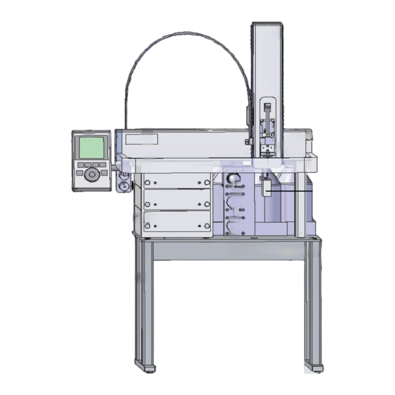
Page 20: Main Components
Cooled stack LC injection valve Table The main components of the Accela Open Autosampler are as follows: • x-, y-axes assembly • Injection unit, z axis • Syringe kit for liquid injections • Fast wash station for two different solvents •... -
Page 21: Dynamic Load And Wash (Dlw)
Introduction Open Autosampler Components To set up the Accela Open Autosampler system, you need a tray set (tray holder and tray) and a stack. You can choose from many optional types of tray sets. For instructions, refer to the Accela Open Autosampler User Guide. - Page 22 The DLW-2 Pump Assembly is equipped with a housing to protect the electrical parts from solvent splashes. Note For a list of the DLW-2 spare parts, see “DLW-2 Option Spare Parts Ordering Information” page 108. Accela Open Autosampler Hardware Manual Thermo Scientific...
- Page 23 205 μL + Injection loop 208 μL + Injection loop volume (204.7) volume Manifold: 90 μL Manifold: 90 μL Holding Loop: 108 μL Holding Loop: 118 μL Syringe Needle: 6.7 μL Installed Injection Loop Installed Injection Loop Thermo Scientific Accela Open Autosampler Hardware Manual...
-
Page 24: Specifications
Introduction Specifications Specifications Table 2 lists the specifications for the Accela Open Autosampler. Table 2. Accela Open Autosampler specifications (Sheet 1 of 3) Component Specification Sample capacity • Six trays with 54 positions for 2 mL vials • Six deepwell or standard microtiter-plates with 96 positions •... - Page 25 Introduction Specifications Table 2. Accela Open Autosampler specifications (Sheet 2 of 3) Component Specification Wash station Fast wash station with two different wash DLW Pumps: • Two pieces. solenoid diaphragm pump • Self-priming – Flow rate range: 100 mL/min at atmospheric pressure (Pump itself, no connections to HPLC system) –...
-
Page 26: Instrument Dimensions
Introduction Instrument Dimensions Table 2. Accela Open Autosampler specifications (Sheet 3 of 3) Component Specification Wash station • DLW Syringe assembly: – Syringe: Gastight Syringe 100 μL with Valflon tip Wetted parts: Glass, PTFE and Valflon – Syringe needle: Gauge 22 (18/25 mm OD/0.41 mm ID) Length: 51 mm, PTFE seal •... -
Page 27: Operating And Environmental Requirements
Introduction Operating and Environmental Requirements Operating and Environmental Requirements Table 3 lists the operating and environmental requirements of the Accela Open Autosampler. Table 3. Operating and environmental requirements Parameter Requirements Operating temperature range 4 –40 °C (39–104 °F) Maximum relative humidity... -
Page 29: Installing The Accela Open Autosampler
Installing the Accela Open Autosampler This chapter describes the installation, contact closure cable connection, computer connection, object positions, and injection valve of the Accela Open Autosampler. Contents • Installing the Autosampler and DLW • System Synchronization Connections • Accela Open Autosampler Object Positions •... -
Page 30: Unpacking The Components
Installing the Accela Open Autosampler Installing the Autosampler and DLW Unpacking the Components An Accela Open Autosampler system is shipped in three boxes. The contents of these boxes are as follows: Box 1: Contains the x-, y-axes assembly, the injection unit, keypad terminal, stand-alone supports, connecting cables, power supply, syringe kit, wash station assembly, safety guard, and miscellaneous parts. - Page 31 Installing the Accela Open Autosampler Installing the Autosampler and DLW 13. 2 pcs. Solvent bottle transfer line including PEEK solvent filter, 10 μm 14. 2 pcs. 1 liter solvent reservoir bottles Figure 3 illustrates the various DLW components as shown in the list above.
-
Page 32: Assembling The Accela Open Autosampler
“DLW-2 Option Spare Parts Ordering Information” page 108. Figure 4. DLW-2 components Assembling the Accela Open Autosampler To assemble the Accela Open Autosampler, follow these procedures: • Installing the Cool Stack • Installing the Injection Unit • Installing the Keypad Terminal •... - Page 33 Installing the Accela Open Autosampler Installing the Autosampler and DLW • Installing the LC Injection Valve • Mounting the DLW Pump Holder Tip Use the screwdrivers in Box 1 to install the different parts with the supplied screws. Installing the Cool Stack Follow these instructions to install the cool stack on the table and the x axis on the cool stack.
- Page 34 Installing the Accela Open Autosampler Installing the Autosampler and DLW 4. Using the supplied M5 8 mm pan head screws (qty 4), secure the cool stack in place × (Figure Figure 6. Installing the cool stack to the table 8 mm pan head screws ×...
- Page 35 Installing the Accela Open Autosampler Installing the Autosampler and DLW To install the x axis on the cool stack 1. Loosen the two Torx™ screws on the three mounting clamps (2 located on top of the stack and 1 on top of the autosampler leg).
- Page 36 Installing the Accela Open Autosampler Installing the Autosampler and DLW Installing the Injection Unit • Install the x-axis stand before you install the injection unit. • Install the injection unit with caution. When installing it for the first time, have someone hold it in place while you insert the mounting screws.
- Page 37 Installing the Accela Open Autosampler Installing the Autosampler and DLW Figure 10. Connecting the injection unit ribbon cable 3. Hold the injection unit in place against the y axis. Make sure the two locating pins on the y axis fit into the two guide pin holes on the injection unit.
- Page 38 Installing the Accela Open Autosampler Installing the Autosampler and DLW Figure 11. Inserting the injection unit mounting Torx screws 5. Install the two remaining Torx screws, B and C, in the left and right mounting holes, respectively. You might have to move the elastic cord slightly to the left to insert Torx screw C into the right hole.
- Page 39 Installing the Accela Open Autosampler Installing the Autosampler and DLW Installing the Keypad Terminal Figure 13. Installing the keypad terminal To install the keypad terminal 1. Install the safety shield on the left and right sides to the outside of the x axis. Use the provided, longer thumbscrew on the side where you plan to install the keypad.
- Page 40 Installing the Accela Open Autosampler Installing the Autosampler and DLW Installing the Power Supply To install the power supply 1. Locate the power supply, the DC power cable, and the AC power cable. 2. Set the power supply switch to OFF.
- Page 41 Installing the Accela Open Autosampler Installing the Autosampler and DLW Mounting the DLW Pump Holder You must always mount the pump holder on the far left of the x axis. The solvent lines are connected to the holder. Moving across the pump holder with the z axis could kink the stabilizing wire.
- Page 42 Installing the Accela Open Autosampler Installing the Autosampler and DLW Figure 17. Installation of the solvent tube assembly to the pump holder 4. Connect the solvent tubing of the DLW tubing kit with the premounted nut to the pump module. Maintain the order: Solvent 1 connected to the left, and Solvent 2 to the right pump module as viewed from the front of the PAL System.
-
Page 43: Installing The Dlw Option
Installing the Accela Open Autosampler Installing the Autosampler and DLW The other end of the cable is connected to the wash station connector on the Control-xt board, as shown in Figure Figure 19. Electrical connection from DLW pump holder to PAL-xt board Installing the DLW Option This section provides instructions on installing the various parts of the DLW option. - Page 44 Installing the Accela Open Autosampler Installing the Autosampler and DLW Figure 20. Mounting the DLW option modules in combination with the injection valve To install the DLW Wash Station 1. Locate the DLW Wash Station module. 2. Attach the holder to the x axis at the selected position as shown in Figure 3.
- Page 45 Installing the Accela Open Autosampler Installing the Autosampler and DLW Figure 21. Attaching the DLW Wash Station to the x axis Tip The waste tube must be positioned below the injection valve. Make sure that the waste liquid flows into the waste container without restriction. The waste tube must always be above the liquid level in the waste container.
- Page 46 Installing the Accela Open Autosampler Installing the Autosampler and DLW Figure 22. Front view of the DLW Syringe Holder assembly To install the DLW syringe holder, follow these procedures: • Preparing and Installing the DLW Syringe • Connecting the DLW Tubing to the Syringe Holder •...
- Page 47 Installing the Accela Open Autosampler Installing the Autosampler and DLW Preparing and Installing the DLW Syringe This section contains information on how to prepare and install the DLW Syringe. To prepare and install the DLW Syringe 1. Prepare the DLW Syringe by inserting the DLW Plunger Holder.
- Page 48 Installing the Accela Open Autosampler Installing the Autosampler and DLW Figure 24. Inserting DLW Syringe into holder CAUTION Make sure to hold the syringe on the metal mount to tighten the syringe. Holding the glass barrel while tightening can damage the seal where the glass meets the metal.
- Page 49 Installing the Accela Open Autosampler Installing the Autosampler and DLW To connect the DLW tubing to the syringe holder 1. Connect the end of the sleeved tubing with the short tubes to the DLW Syringe Holder assembly. See “Mounting the DLW Pump Holder ”...
- Page 50 Installing the Accela Open Autosampler Installing the Autosampler and DLW Figure 25. Inserting the DLW Syringe Holder assembly into the injection unit 2. Press the syringe holder firmly against the z-axis slider to ensure that the holder engages. CAUTION Do not press against the DLW Actuator/Solenoid. The mounting of the latter to the DLW Manifold is fragile and might break.
- Page 51 Installing the Accela Open Autosampler Installing the Autosampler and DLW 3. Tighten the knurled screw to fix the holder assembly to the syringe slider (Figure 26). Figure 26. Fixing syringe holder to syringe slider 4. Move the plunger up (plunger holder) until the thread of the screw catches the thread of plunger bushing.
- Page 52 Installing the Accela Open Autosampler Installing the Autosampler and DLW 5. Tighten the holding screw to secure the syringe holder position. CAUTION Make sure the removable needle fits leak-tight to the syringe. A Teflon seal is provided. When installing the seal, ensure that the hole is open and that no fuzzy (lint) polymer material, which might clog the needle, is in the path.
- Page 53 Installing the Accela Open Autosampler Installing the Autosampler and DLW Injection Valve Plumbing and Connection to DLW Wash Station To plumb the injection valve and connect it to DLW Wash Station 1. Connect the injection valve waste line from port 2 (for example, the standard Cheminert...
-
Page 54: Electrical Connections
Installing the Accela Open Autosampler Installing the Autosampler and DLW Electrical Connections This section contains information on setting up the electrical connections of the Accela Open Autosampler. Electrical Connections for Single Injection Valve Setup CAUTION Always power off the Open Autosampler before connecting or disconnecting the DLW cable or any other accessory cables. - Page 55 Installing the Accela Open Autosampler Installing the Autosampler and DLW DLW Option Installation in Combination with 2- or 4- Injection Valves You can combine the DLW option with Open Autosampler systems using a setup of 2- or 4-injection valves (Figure 31).
- Page 56 Installing the Accela Open Autosampler Installing the Autosampler and DLW Figure 32. Electrical connections to 4-injection valves, daisy-chaining with PAL-xt system Installing the Power Supply for the Cooled Stack The power supply for the cooled stack has a built-in control unit with display (P/N CH-952995).
-
Page 57: System Synchronization Connections
The system interconnect cables and adapter cables that synchronize the run signals for an LC or LC/MS system with an Accela Open Autosampler depend on the Accela pump model, the mass spectrometer model, and whether the LC system includes an Accela detector. -
Page 58: Accela Open Autosampler Object Positions
Note Remove the syringe adapter from the injection unit before performing the following steps. The objective is to define the reference positions for all Accela Open Autosampler objects. Make sure to properly mount the tray holders, valve drives, and wash station to the Accela Open Autosampler x axis. -
Page 59: Description Of Object Positions
Installing the Accela Open Autosampler Accela Open Autosampler Object Positions Figure 33. Menu screen object Tray Holder 4. Select Position X and press ENTER. The injection unit moves to the previously defined x-axis position. 5. Rotate the outer knob to adjust the x-axis position to the tray holder reference position. - Page 60 Installing the Accela Open Autosampler Accela Open Autosampler Object Positions Figure 34. Stack reference position For the object stack/tray cooler, you must properly position the x, y, z axes in the Open Autosampler system. After x-, y-, z-axis positioning of stack cooler model 6DW or 12MT, add the following steps to verify the correct installation of the module.
- Page 61 Figure 35. Demonstrating a possible inclination of the tray in x, y, z axes Definition of a Tray Row and Column The Accela Open Autosampler defines rows and columns by the order in which samples are treated. A row is not associated with an x or y axis.
- Page 62 Installing the Accela Open Autosampler Accela Open Autosampler Object Positions Figure 36. Tray type VT54 Correction for Inclination in X, Y, or Z Axes The following describes the correction using the path to the Utilities section. To correct for inclination in x, y, or z axes 1.
- Page 63 The three corner points are now adjusted for a possible inclination of the tray in any axis. Without further teaching, the Accela Open Autosampler interpolates a possible deviation from an ideal axis position for the other vials, caused by variance from the horizontal.
- Page 64 Installing the Accela Open Autosampler Accela Open Autosampler Object Positions Wash Station: Wash1/Wash2 Reference Point Figure 40 shows the Wash Station Wash1/Wash2 reference point. Figure 40. Wash station Wash1/Wash2 reference point For a fast wash station, the reference positions are the two holes in the wash vial caps (Figure 40).
- Page 65 Menu > Setup > Objects > Wash Stations > Wash2 Waste Reference Point, Injectors (Waste) The waste position represents an injector within the Accela Open Autosampler software. It is defined in the object class, Injectors. The reference position for the waste port—a hole (slightly larger than the needle guide)—has...
- Page 66 Installing the Accela Open Autosampler Accela Open Autosampler Object Positions Injection Valve Reference Points For an LC Valve the reference position is the valve needle guide fitting mounted on the top valve port (Figure 43). Figure 43. LC Valve reference point The lower needle guide of the injection unit is centered in the valve needle guide fitting.
- Page 67 Installing the Accela Open Autosampler Accela Open Autosampler Object Positions 4. Slowly rotate the outer knob to adjust the needle penetration depth. The syringe moves down stepwise into the injection port. 5. When the syringe needle tip enters the valve needle guide, slow down the Z-movement again.
-
Page 68: Injection Valve
This section contains information about the injection valve. Valve Drives and Valves – General Remarks An Accela Open Autosampler can be equipped with one LC injection valve connected and controlled through the auxiliary interface (AUX). If you must configure more than one valve, or if an auxiliary interface is occupied by another module, such as a dilutor, then the autosampler requires multiposition or serial valve drives. - Page 69 Installing the Accela Open Autosampler Injection Valve Figure 47. Flow path of standard LC injection valve (Cheminert type) Table 6 lists the specifications for a standard LC injection valve. Table 6. Standard LC injection valve specifications Component Specification Valco/VICI Cheminert...
- Page 70 Installing the Accela Open Autosampler Injection Valve Valve Needle Guide and Needle Seal All valves are equipped with a special valve needle guide fitting. This fitting has a wide diameter to connect with the syringe needle guide on the injection unit. The valve needle guide also has a countersunk hole to guide the syringe needle into the injection port.
- Page 71 Installing the Accela Open Autosampler Injection Valve Interval to Replace Needle Seal The interval to replace the needle seal depends on the number of penetrations. Consider these two factors when deciding to replace the needle seal: • Leak, seal not reliable Remove the needle seal from the inlet port and insert a syringe manually with the corresponding needle gauge (standard Gauge 22 OD 18/25 mm).
-
Page 73: Operating The Accela Open Autosampler
Operating the Accela Open Autosampler This chapter describes how to operate the Accela Open Autosampler including how to use the control terminal, methods, job queue, utility functions, and logfile; and how to set up functions. Contents • Control Terminal •... -
Page 74: Menu Screens
Operating the Accela Open Autosampler Control Terminal Figure 49. Accela Open Autosampler control terminal and conventions Menu Screens The control terminal displays different menu screens, depending on the Accela Open Autosampler operating status and the particular function that you are accessing. All menu screens have the same basic format. -
Page 75: Function Keys
Operating the Accela Open Autosampler Methods Function Keys Functions (keys F1, F2, F3, and F4) correspond to the options for a particular menu, directly above each function key label. Pressing the function key labeled Home always returns to the Job Queue menu. -
Page 76: Editing And Viewing Methods
Operating the Accela Open Autosampler Methods To create a new method 1. Choose Menu > Methods > Select the Insertion Point > Instrument Method. 2. Enter a new method name. After you create a copy of the method, the method parameters appear and can now be edited. -
Page 77: Deleting Methods
Operating the Accela Open Autosampler Job and Job Queue Deleting Methods You can delete methods from the Methods menu, but you cannot delete methods in use by an active job. Complete the following menu selections to delete a method. Job and Job Queue A job bundles the specified tray with the designated vials (samples) and with the method to run those samples. -
Page 78: Building And Starting A Job Queue
Operating the Accela Open Autosampler Job and Job Queue Building and Starting a Job Queue To build and start a job queue 1. Power on the Accela Open Autosampler. The JOB QUEUE display opens (Figure 52). Figure 52. JOB QUEUE 2. -
Page 79: Canceling A Job Queue
Operating the Accela Open Autosampler Utility Functions Canceling a Job Queue To cancel a job queue 1. In the JOB QUEUE display, press STOP. 2. Select one of the available options: Continue, Sample, Job, or Job Queue. • To resume processing with the current sample, select Continue. -
Page 80: Syringe
Operating the Accela Open Autosampler Utility Functions Figure 53. Selecting Utilities functions Syringe Table 8 lists the functions available for Syringe by pressing the appropriate function key. Table 8. Utility function keys for Syringe Function key Description F1 Chang Syr The syringe is moved to a position where the syringe assembly can be completely lowered to ease removal of the syringe adapter. -
Page 81: Tray
Operating the Accela Open Autosampler Utility Functions Table 9. Syringe items (Sheet 2 of 2) Item Description Fill Strokes Number of fill strokes. All fill strokes, except the last one, use the selected fill volume. If the selected sample volume is greater than the fill volume, the sample volume is used for all fill strokes. -
Page 82: Injector
Operating the Accela Open Autosampler Utility Functions Table 11 lists the items you can select to change the tray configuration. Table 11. Tray items Item Description Needle Penetr Needle penetration depth into the sample vial. You can change the needle penetration depth for the selected tray by entering the value that you want. -
Page 83: Wash Station
Operating the Accela Open Autosampler Utility Functions Table 13 lists the item you can select to change the injector configuration. Table 13. Utility item Item Description Needle Penetr By selecting the Needle Penetr parameter, you can check or change the injector needle penetration value. To ensure reproducible sample injections and minimize carryover, make sure that the needle penetration depth is accurately set. -
Page 84: Vial
Operating the Accela Open Autosampler Utility Functions Vial Table 16 lists the functions available for a vial by pressing the appropriate function key. Table 16. Utility function keys for a vial Function key Description F3 Movto Vial The injection unit moves to the selected vial type. By selecting the Needle Penetr parameter, you can check or change the wash station needle penetration value. -
Page 85: Tools
Operating the Accela Open Autosampler Utility Functions Table 19. Dilutor items Item Description Syringe Indicates the dilutor side-port syringe inserted in the z axis. Use this function to select another syringe size. Syr Dilut Pos Moves the plunger of the side port syringe up by the specified distance. -
Page 86: Logfile
Operating the Accela Open Autosampler Logfile Table 21 lists the items you can select to change the tools configuration. Table 21. Tools items Item Description Teach Point The reference point at which to teach the Object (Tool; MHETool) is selectable. The MHETool needs no extra position. -
Page 87: Hardware
Operating the Accela Open Autosampler Info Functions Hardware Table 22 lists Info functions items for hardware. Table 22. Info functions items for hardware Item Description CPU SNo The serial number (S/N) of the PCB APR CPU is displayed. CPU ID Version number of the PCB APR CPU. -
Page 88: Free Objects/Free Items
Operating the Accela Open Autosampler Info Functions Table 24. Info functions items for maintenance (Sheet 2 of 2) Item Description Inject Count Monitors the number of injections. The number of injection valve switches is a helpful tool for deciding on replacement parts for the injector system. -
Page 89: Setup Functions
Operating the Accela Open Autosampler Setup Functions Setup Functions The Setup functions, selectable from the Menu screen (Figure 55), allow access to various functions for the PAL System. The Sound, Time, and Objects are basic functions that you use at installation or if changes have been made over time. -
Page 90: Objects
136. Communicating with the Computer This section describes how the Accela Open Autosampler communicates with a computer. The PAL System provides a serial communication protocol with a computer. The Accela Open Autosampler system requires a dedicated APR Control-xt board and PAL Firmware level 4.1.x or later. - Page 91 Operating the Accela Open Autosampler Communicating with the Computer Figure 56. COM Port Settings A quick way to check whether serial communication with the PAL System can be established is to use the PAL Loader software. For further information, see “PAL Loader”...
-
Page 93: Chapter 4 Operating The Temperature Controllable Stack Coolers
The stack/tray cooler temperature is preset by the factory to 10 °C. To change the value 1. Press P briefly (less than two seconds) until SP1 appears. 2. Use the increment/decrement keys to select the desired value. 3. Press P again. Thermo Scientific Accela Open Autosampler Hardware Manual... -
Page 94: Temperature Control
To reach 4 °C in the analytical solution, program a set value lower than 4 °C. The material used for the sample may be glass, polypropylene, polyethylene, or similar polymer products. All of these have excellent insulating properties. Accela Open Autosampler Hardware Manual Thermo Scientific... -
Page 95: Temperature Alarm
• For high-throughput analysis–typical cycle time of 60 seconds or less per analysis–leave the drawers open between injections. • For longer cycle times, use the Accela Open Autosampler option to close the drawer after each sampling. You can change the Restore mode to keep the drawer open or closed during a run. -
Page 96: Condensation Build-Up
This section contains information about condensation build-up in stack coolers and tray coolers. Condensation Build-Up in Accela Open Autosampler Stack Coolers Condensation build-up is directly related to the temperature and relative humidity/ temperature in ambient air (dew point). Long-term tests showed very little build-up of condensation in an environment of relative humidity up to 60 percent and 22 ±2 °C ambient... -
Page 97: Condensation Build-Up In Pal Tray Coolers
As long as deep well, microtiter plates, or 2 mL vials (TrayType VT54) are being handled, this change is positive with respect to condensation build-up. It would also double the capacity of the trays. Thermo Scientific Accela Open Autosampler Hardware Manual... -
Page 99: Maintenance
Maintenance This chapter describes the maintenance procedures that can help you operate the Accela Open Autosampler under optimal conditions. To ensure accuracy and precision of the Accela Open Autosampler. Follow the maintenance procedures at the suggested intervals in Table If you use the system extensively (for example, nights and weekends), or if you use corrosive solvents, you might need to perform the maintenance procedure more frequently. - Page 100 Maintenance Table 27. Routine maintenance for Accela Open Autosampler (Sheet 2 of 2) Maintenance step Interval Replace the DLW syringe needle. Observe Only as needed (for example, if bent) the correct placement of the Teflon seal. Check all connections for tightness.
- Page 101 Fan cooling prolongs the life of the electronic components. CAUTION Check the fan regularly. If the fan fails, the power supply still operates and can pass safety tests, even when the temperature is dangerously high and might damage the system electronics. Thermo Scientific Accela Open Autosampler Hardware Manual...
-
Page 103: Troubleshooting
Valve ports not plumbed correctly Check plumbing connections. to the pump, the detection system, or both Wrong valve type specified Check valve type by choosing Menu > Setup > Objects > Injectors > LCVlv1 > Valve. Thermo Scientific Accela Open Autosampler Hardware Manual... - Page 104 Needle penetration depth set Adjust the injection valve needle penetration. incorrectly for the injection valve The syringe plunger speed set too Reduce inject speed in method. high, resulting in excessive pressure in inlet Accela Open Autosampler Hardware Manual Thermo Scientific...
- Page 105 • Is the retaining nut tight? • Is the PTFE seal installed? • Is the needle entry free of debris, not clogged? • Is the correct needle diameter (gauge 22) used? Thermo Scientific Accela Open Autosampler Hardware Manual...
- Page 106 Air gaps not formed. Liquids of Verify the DLW method parameter for Airgap different type blending into each Volume. other. Prime entire system. Accela Open Autosampler Hardware Manual Thermo Scientific...
- Page 107 Blocked solvent frits in wash solvent Clean the frits in an ultrasonic bath with an reservoir appropriate solvent. If flow is not ensured after cleaning, replace frits. Replace wash solvent and clean reservoir bottle and tubing carefully. Thermo Scientific Accela Open Autosampler Hardware Manual...
-
Page 108: Cooled Stack Power Supply Error Messages
You must pay special attention to all tubing connections, including these common mistakes in routine practice: • Nut and ferrule not connected leak tight (see Nut and Ferrule Tightening) • Incorrect pilot distance (see “Incorrect Pilot Distance” page Accela Open Autosampler Hardware Manual Thermo Scientific... - Page 109 Check the seal when liquid is pumped through the system. In case a leak is observed, tighten once more by another quarter turn. Always move from a leaking to a tight seal; never move backward from an overtightened seal. Thermo Scientific Accela Open Autosampler Hardware Manual...
- Page 110 3. Move the nut and ferrule together into the female counterpart for the connection (Figure 58). Make sure to maintain pressure on the tube to avoid the tube slipping backwards, out of position. 4. Tighten the nut as described in the previous section. Accela Open Autosampler Hardware Manual Thermo Scientific...
- Page 111 Hold the tube on the two sides of the cut with flat-nose pliers and twist the tube until it breaks. You can use the same procedure for polymer tubing by replacing flat-nose pliers with tweezers with a flat tip. Thermo Scientific Accela Open Autosampler Hardware Manual...
- Page 112 Figure 61 shows the various forms of the ferrules from different manufacturers. Although some of them are close in shape to what you need, they are not close enough to exchange without risk. Accela Open Autosampler Hardware Manual Thermo Scientific...
-
Page 113: Solvent Delivery Pumps Not Priming
3. Select this path from the local terminal workstation. Menu > Utilities > Wash Station > selected wash station The delivery pump and the DLW Actuator are activated, and you can collect the delivered flow at the DLW syringe needle. Thermo Scientific Accela Open Autosampler Hardware Manual... -
Page 114: Standard Chromatographic Tests
Note The levels provided in these tests do not reflect the specification value for careover or repeatability. The test results will confirm if the system is working properly with reasonable effort and within the expected time frame. The tests are comparable to Operational Qualification (OQ) tests. Accela Open Autosampler Hardware Manual Thermo Scientific... -
Page 115: Carryover Test With Uv-Detection
UV-detection. Table 32. Carryover tests with UV-detection (Sheet 1 of 2) Parameter Value Syringe 100 μL DLW Sample Volume 7 μL Airgap Volume 3 μL Front Volume 5 μL Rear Volume 5 μL Thermo Scientific Accela Open Autosampler Hardware Manual... -
Page 116: Repeatability Test With Uv-Detection
1.9 μm • Column temperature: Ambient • Mobile phase Water:acetonitrile = 90:10 +0.1% TFA • Gradient: Isocratic for 2 min Wash Solvents • Wash1: Water + 0.1% TFA • Wash2: Acetonitrile + 0.1% TFA Accela Open Autosampler Hardware Manual Thermo Scientific... - Page 117 Inject Speed 5 μL/S Pre Inj Del 500 ms Pst Inj Del 500 ms Valve Clean Time Solvent 2 Post Clean Time Solvent 2 Valve Clean Time Solvent 1 Post Clean Time Solvent 1 Thermo Scientific Accela Open Autosampler Hardware Manual...
-
Page 119: Chapter 7 Replaceable Parts
Replaceable Parts This chapter describes the replaceable parts for the Accela Open Autosampler and the Dynamic Load and Wash (DLW) option. Contents • DLW Pump Module • DLW Wash Station • DLW Syringe • DLW Syringe Holder Assembly • DLW Option Spare Parts Ordering Information •... -
Page 120: Dlw Pump Module
You can exchange the following parts individually from the DLW syringe assembly: • DLW syringe 100 μL • DLW syringe plunger (for syringe 100 μL) • DLW syringe plunger holder • DLW syringe retaining nut • DLW syringe replaceable needles Accela Open Autosampler Hardware Manual Thermo Scientific... -
Page 121: Dlw Syringe Holder Assembly
PAL DLW Pump Kit (single module), incl. electrical connections, 24 V 00950-01-00311 Aspiration Tube Kit, consisting of: • 1 pc. Tube PFA • 1 pc. PEEK solvent filter 10 μm • 1 pc. Plug with feed through hole Thermo Scientific Accela Open Autosampler Hardware Manual... - Page 122 PAL DLW Wash Station Block, complete assembly (incl. centering plate) 00950-01-00334 PAL DLW Wash Station Insert Kit, consisting of: • 2 pcs. Inserts • 1 pc. Waste Connector • 5 pcs. Dummy Plugs Accela Open Autosampler Hardware Manual Thermo Scientific...
- Page 123 Replacement plunger for syringe SYRC DLW-R.; pkg of 10 00950-01-00327 PAL DLW Plunger Holder 00950-01-00328 Needle Kit for PAL DLW Option, gauge 22 PST 3, l 51 mm (3 pcs. per pack); incl. needle retaining nut Thermo Scientific Accela Open Autosampler Hardware Manual...
- Page 124 100 μL syringe, without syringe needle 00950-01-00317 Kit PAL DLW Holding Loop with needle adapter mounted 00950-01-00318 PAL DLW Manifold Kit, complete, assembled 00950-01-00319 PAL DLW Flow Diverter, pkg of 1 Accela Open Autosampler Hardware Manual Thermo Scientific...
- Page 125 1 00950-01-00323 PAL DLW Needle Length Guide tool, pkg of 1 00950-01-00324 PAL DLW Needle Holder Kit Note Individual parts or the total composition of spare part kits can change without notice. Thermo Scientific Accela Open Autosampler Hardware Manual...
-
Page 126: Dlw-2 Option Spare Parts Ordering Information
Part name/number Description Illustration DLW Pump Module 00950-01-00359 PAL DLW-2 Syringe Holder assembly; complete assembly with holding loop and 100 μL syringe installed 00950-01-00360 Kit PAL DLW-2 holding loop with need and adapter mounted Accela Open Autosampler Hardware Manual Thermo Scientific... -
Page 127: Control-Xt Board
To install the control-xt board Note The Control-xt board replaces the control board (PN CH-952589). This board is required for the Accela Open Autosampler system and operates only at PAL Firmware level 4.1.x or later. 1. Follow the sequence shown in... -
Page 128: Injection Valve And Valve Rotor
2. Unscrew the Torx screw at the valve adapter, which holds the valve to the valve drive. 3. Check that the valve guide pin remains at its position and observe the guide marks as shown in Figure 46 page 4. Install the replacement valve in the reverse order. Accela Open Autosampler Hardware Manual Thermo Scientific... - Page 129 Replaceable Parts Injection Valve and Valve Rotor Figure 63. Replacing the VICI/Valco Cheminert injection valve Thermo Scientific Accela Open Autosampler Hardware Manual...
-
Page 130: Cleaning Or Replacing Valve Rotors
5. Tighten the hex screws carefully and evenly to reach a parallel seat of valve stator and body. Figure 64. Rotor replacement of Cheminert valve Injection Unit For details on the parts of the injection unit, see “Installing the Injection Unit” page Accela Open Autosampler Hardware Manual Thermo Scientific... -
Page 131: Appendix A Reference Information
• Naming Convention • Special Functions • PAL Firmware Overview • PAL Firmware Error Codes • External Connectors for Accela Open Autosampler • System Limitations • Interfacing the Open Autosampler to Other Devices Thermo Scientific Accela Open Autosampler Hardware Manual... -
Page 132: Glossary
Reference Information Glossary Glossary Table 37 provides a list of glossary terms related to the Accela Open Autosampler. Table 37. Accela Open Autosampler glossary (Sheet 1 of 2) Terms Description Cycle The specific operations necessary to process one sample. The cycle operations are repeated for each sample within a job. - Page 133 Reference Information Glossary Table 37. Accela Open Autosampler glossary (Sheet 2 of 2) Terms Description PAL Object list If you add a PAL module (hardware) to an instrument, you must load several objects into the firmware. These objects are collected in an object list and stored in a file with the extension .pol.
-
Page 134: Naming Convention
Naming Convention Naming Convention This section recommends the standard naming convention for the Accela Open Autosampler. Following this convention will allow the PAL setup to be preconfigured for certain applications. This will simplify software backups and application development, and will improve technical support and training. -
Page 135: Special Functions
Settings that you set rarely—perhaps at the time of the Accela Open Autosampler system installation—are hidden at level 1 (User Level) and revealed at level 2 (Extended User Level). This also protects the Accela Open Autosampler in group use. Nevertheless, you should become familiar with the important points as described. - Page 136 The Identification of the system provides the opportunity to assign users, site, and system names. You can enter the serial number of the Accela Open Autosampler at this level. After loading a fresh PAL Firmware backup file, the SNo. is displayed as XXXXXX.
- Page 137 PlgChnge Pos Changes a syringe using the Chnge Syr menu function and moves the plunger up to the position specified by this item. For normal use, accept the default values. Thermo Scientific Accela Open Autosampler Hardware Manual...
- Page 138 Thermo PAL driver. LC-Inj The standard cycle for the HPLC technique. For details, refer to Chapter 5 in the Accela Open Autosampler User Guide for LC Devices. LC-Cut The cycle for column switching with two valves for the HPLC technique.
- Page 139 For details, see “PAL Firmware Overview” page 136 and refer to Chapter 5 in the Accela Open Autosampler User Guide for LC Devices. HS-Inj The standard cyle for the GC headspace technique. For details, see “PAL Firmware Overview”...
- Page 140 Warning: These items are typically used for service. If applied, do not leave the test settings for longer than a few minutes. Leaving the current setting in a critical range can damage the motor. Accela Open Autosampler Hardware Manual Thermo Scientific...
- Page 141 Performs a sensor check. F2 Check Z: Tests the vial detection sensor and Needle Guide Blocking function. These tests are only required when the Accela Open Autosampler operates erratically. In such cases, contact a Thermo Fisher Scientific representative. Test Switches X-Limit = The actual status of the x-axis sensor.
-
Page 142: Section F3-Setup/Objects
The path offset x, y, z is used only if a path is assigned to the specified tray holder. Typically a stack or agitator uses a path. Wash Stations The wash station and its positions, Wash1 and Wash2, are visible and selectable. Accela Open Autosampler Hardware Manual Thermo Scientific... - Page 143 Selecting an item (for example, Home) enables the F1 function key and displays Check Pos on the screen. Activating this function provides the possibility of verifying x, y-, z-axes values for this particular position. Thermo Scientific Accela Open Autosampler Hardware Manual...
- Page 144 High Speed or High Torque. Out Exp Box The Out Expansion box provides 8 TTL contacts and 8 relay contacts (24 V contact closure). The optional module (box) is connected and controlled by Interface 2. Accela Open Autosampler Hardware Manual Thermo Scientific...
- Page 145 Remark: At PAL Firmware level 4.1.x, these items of the Y motor have been made available at the Extended User Level. Items displayed in italics are available beginning with PAL Firmware level 4.1.x. Thermo Scientific Accela Open Autosampler Hardware Manual...
- Page 146 Total height of the vial including cap to seal if applicable. Measured in mm. Remark: The sum of the plate thickness and vial height adds up to the total height This is the point where the injection unit expects an object. Accela Open Autosampler Hardware Manual Thermo Scientific...
- Page 147 Z Retract The distance to lift up the syringe slider before the y-, z-axes assembly moves across the unit can be specified, expressed in mm. Thermo Scientific Accela Open Autosampler Hardware Manual...
- Page 148 Deepwell Plate, make the change in the Tray Type class of Object. For fine tuning, you can use the Offset items from the class Trays. Accela Open Autosampler Hardware Manual Thermo Scientific...
- Page 149 • Pattern Type, Staggrd+ (Figure The sample or well positions are arranged in a staggered pattern. Offset of second Row is shifted by + 50% of hole pattern. Figure 68. Pattern tray type -of Staggered+ Thermo Scientific Accela Open Autosampler Hardware Manual...
- Page 150 This item is available at the User Level in the section, Utilities/Tray, and can be used for fine tuning a tray installed in a tray holder. Important for well-plates 384 installed in a Stack. Remark: Position#1 is the only correction point. Accela Open Autosampler Hardware Manual Thermo Scientific...
- Page 151 Correction for inclination of a tray in Y-row direction. For details, see Section 4.2.3.2 above. dzRow Correction for inclination of a tray in Z-row direction. For details, see Section F, “Description and Installation,” point 4.2.3.2 above. Thermo Scientific Accela Open Autosampler Hardware Manual...
- Page 152 Typical needle length is 51 mm; maximum penetration must not exceed 48 mm. Needle Penetr This item is identical to that at the User Level. The value defined at this level is mirrored in the Extended User Level. Accela Open Autosampler Hardware Manual Thermo Scientific...
- Page 153 In the case of a fast/active wash station, the syringe needle is pulled out of the wash port. The wash solvent flows without restriction. As a result, you must consider higher solvent consumption. Items displayed in italics are available beginning with PAL Firmware level 4.1.x. Thermo Scientific Accela Open Autosampler Hardware Manual...
-
Page 154: Pal Firmware Overview
Reference Information PAL Firmware Overview PAL Firmware Overview Figure 70. PAL Firmware Overview, Page 1 Accela Open Autosampler Hardware Manual Thermo Scientific... - Page 155 Reference Information PAL Firmware Overview Figure 71. PAL Firmware Overview, Page 2 Thermo Scientific Accela Open Autosampler Hardware Manual...
- Page 156 Reference Information PAL Firmware Overview Figure 72. PAL Firmware Overview, page 3 Accela Open Autosampler Hardware Manual Thermo Scientific...
- Page 157 Reference Information PAL Firmware Overview Figure 73. PAL Firmware Overview, Page 4 Thermo Scientific Accela Open Autosampler Hardware Manual...
-
Page 158: Pal Firmware Error Codes
Module CRC not valid MenuProc Index out of Range MenuProc Address contains NIL Pointer FuncProc Address contains NIL Pointer Invalid Function Key Invalid MenuTable Index MenuTable Pointer contains NIL Invalid Object Focus in GetItemPtr Accela Open Autosampler Hardware Manual Thermo Scientific... - Page 159 Invalid Needle Magnet Parameter Answer Count Head Tool ID not valid Invalid Head Tool Parameter Answer Count Head Board Revision Level invalid Invalid Head Board Revision Level Parameter Answer Count Heater Power Count Invalid Thermo Scientific Accela Open Autosampler Hardware Manual...
- Page 160 Target position is below low_limit_steps Target position is above high_limit_steps No Syringe Found Syringe Volume out of Range Tray Index out of Range Not Appropriate Object Class Temperature is out of Heater Limits Accela Open Autosampler Hardware Manual Thermo Scientific...
- Page 161 ReportLog Index out of Bounds Invalid Vial Transport mode Invalid Barcode mode Memory Full Found No Vial Address Error detected Bus Error detected Zero Division detected Spurious Interrupt detected Format Error and uninitialized Interrupt Thermo Scientific Accela Open Autosampler Hardware Manual...
- Page 162 Axis Target Position Error Motor Current fault Time Table Full No Tray found at this position z-Axis Collision Error Mandatory Parameter Missing Invalid Vici Valve Drive Invalid Vici Valve Position Invalid Vici Valve Status Accela Open Autosampler Hardware Manual Thermo Scientific...
-
Page 163: External Connectors For Accela Open Autosampler
Reference Information External Connectors for Accela Open Autosampler Table 46. PAL firmware error codes (Sheet 6 of 6) Error code number Error message Aux Motors are not supported by this Hardware OutExpBox is currently disabled Output currently used by OutExpBox... - Page 164 Reference Information External Connectors for Accela Open Autosampler • Connector SER2 • Connector TERMINAL or SER3 • Connector wash station Connector Power Signal name +36 V Connector Fuse Fuse type Description Fuse Type FST 5 × 20 Rating 6.3 A...
- Page 165 Reference Information External Connectors for Accela Open Autosampler Connector AUX1 Signal name Motor A1 Motor B1 Temp + Sens Heater 11,12 Motor A2 13,14 Motor B2 Temp – 15,18,19 20,10 36 V Connector AUX2 Signal name Motor A1 Motor B1...
- Page 166 Reference Information External Connectors for Accela Open Autosampler Connector MODBUS Signal name 2 – 7 36 V 9 – 14 Connector INTERFACE 1 Signal name Pwr-Out1 + Pwr-Out2 + SW-Out1 NO SW-Out1 COM SW-Out2 NO Opto-In1 + TTL-In1 Pwr-Out1 –...
- Page 167 Reference Information External Connectors for Accela Open Autosampler Connector INTERFACE 2 Signal name TTL-In1 TTL-In2 TTL-In3 TTL-Out1 TTL-Out2 TTL-Out3 Opto-In1 + Opto-In2 + SW-Out1 NO SW-Out2 NO Pwr-Out1 + Pwr-Out2 + 14-19 Opto-In1 – Opto-In2 – SW-Out1 COM SW-Out2 COM Pwr-Out1 –...
- Page 168 Reference Information External Connectors for Accela Open Autosampler Connector SER1 Signal name DTR bridged with Pin 7. Special grounding; do not alter. RTS bridged with Pin 4; do not alter. Connector SER2 Signal name Accela Open Autosampler Hardware Manual Thermo Scientific...
- Page 169 Reference Information External Connectors for Accela Open Autosampler Connector TERMINAL or SER3 Signal name Connector wash station Signal name PWR – Out1+ PWR – Out1 – PWR – Out2+ PWR – Out2 – Thermo Scientific Accela Open Autosampler Hardware Manual...
-
Page 170: System Limitations
System Limitations This section contains information about system limitations. Accela Open Autosampler You can operate the DLW Option only with an Accela Open Autosampler, which requires PAL Firmware level 4.1.x and the APR Control-xt board. Sample Volume The current version of the DLW Option can handle sample volumes of 2–100 μL. - Page 171 To assign a physical Event (for example, SW-Out 1) to an existing signal Object (Injected), complete the following menu selections: The Accela Open Autosampler is shipped with all cycle events predefined, as shown in Table 47. If you need a different physical signal, then you must assign a new Event to the Object signal.
- Page 172 An LC Sync Cable is supplied, which has the PAL Interface 1 connector mounted. The HPLC system side has a 25-pin connector for 600 pump and 1250 pump, and a 2-wire connector for the detectors. Accela Open Autosampler Hardware Manual Thermo Scientific...
-
Page 173: Appendix B Pal Loader
(Items), local methods, and jobs, are saved as one file. The PAL Loader software has a second function of loading the firmware or a complete backup file to the Accela Open Autosampler. The PAL Loader application has always been part of the Accela Open Autosampler. -
Page 174: New Features Of Pal Loader Software 2.1.X
PAL Loader software version 2.1.x requires Windows 2000, XP, or Vista™. It does not support earlier Windows versions, such as Windows 95, 98, or NT. If installation is necessary in this environment, use PAL Loader version 1.1.1. Accela Open Autosampler Hardware Manual Thermo Scientific... -
Page 175: Pal Loader Software Version 2.1.X Installation
The two subfolders Backup and Update are automatically created at installation in this directory: drive:\Users\Public\Public Documents\PAL\Loader The directory allows writing temporary files, with no write protection and, in a network environment, the User Profile is always provided to the user at logon. Thermo Scientific Accela Open Autosampler Hardware Manual... -
Page 176: Multiple Shortcuts Assignment
This setup facilitates the handling of a number of PAL Systems from a single computer. You can create a shortcut of the PALloader.exe file to the desktop. After you create the shortcut, right-click the shortcut icon and choose Properties from the shortcut menu. See Figure Accela Open Autosampler Hardware Manual Thermo Scientific... -
Page 177: Dedicated Shortcut For Serial Communication
Explorer) and not from the PAL Loader desktop icon. Dedicated Shortcut for Serial Communication Add this extension to the command line: … .exe /CommunicationType=0 /ComPort=x Figure Where: • Type=0: Serial Communication Protocol • x= Com Port Number Thermo Scientific Accela Open Autosampler Hardware Manual... -
Page 178: Creating Multiple Shortcuts
LAN shortcut icons with IP address 20 and 21 as well as two serial shortcut icons with COM port numbers 1 and 3. Double-clicking the icon opens the PAL Loader software with the assigned communication protocol and address (port). Accela Open Autosampler Hardware Manual Thermo Scientific... -
Page 179: Pal Loader Software Operation
PAL Loader Software Operation This section contains information about how to operate the PAL Loader software. Starting the PAL Loader Software Click the PAL Loader icon located on the desktop. Figure 80. PAL Loader software icon Thermo Scientific Accela Open Autosampler Hardware Manual... -
Page 180: Setting Up Com Ports
Note The limitation of PAL Loader software version 1.1.1—that only ports COM1 to COM4 can be addressed—has been eliminated in version 2.1.x. Also, COM ports do not need to be in consecutive order. Figure 82. Setup dialog box for Serial Communication Accela Open Autosampler Hardware Manual Thermo Scientific... - Page 181 The standard settings for serial communication are shown in Figure Note The application (PAL Loader software) actively sets the communication parameters, and the baud rate is set for optimized use. Figure 83. COM1 Properties dialog box – Port Settings page Thermo Scientific Accela Open Autosampler Hardware Manual...
-
Page 182: Serial Communication
Figure 84. Clicking Info Figure 85. PAL information received When the PAL Loader application receives information from the Accela Open Autosampler, the red LED on the back of the electronic board blinks. This blinking LED indicates that the processor is in so-called Loader Mode, which means that the processor enables receiving the firmware or writing to memory. -
Page 183: Reset Pal-Xt To Serial Communication
• Constantly on: Data transfer process is in progress. The position of the LED in the APR Control-xt board is between the buzzer and the connector for the wash station. Explanation for the Communication Protocol Settings Table 48. Accela Open Autosampler communication parameters Parameter Explanation Remarks... -
Page 184: Backing Up The Pal Firmware
Note You can also use the Info button to establish and check communication with the PAL System using the PAL Loader software. If you cannot establish communication with the PAL System, see “Troubleshooting” page Accela Open Autosampler Hardware Manual Thermo Scientific... - Page 185 Loader application displays this last used rate. 6. Activate the process by clicking Start Backup (Figure 88). The process is initialized and takes approximately 3–5 minutes. Figure 88. Backup process for serial communication completed Thermo Scientific Accela Open Autosampler Hardware Manual...
-
Page 186: Updating The Pal Firmware
Info. Updating the PAL Firmware IMPORTANT Do not move any part of the Accela Open Autosampler, such as the x axis, and if possible do not use other computer functions during the backup and update process. - Page 187 90). 5. Browse to the appropriate file (extension .sss) to upgrade the PAL Firmware. Note To establish and check communication from the Accela Open Autosampler using the PAL Loader software, you can also use the Info button. If communication with the Accela Open Autosampler cannot be established, see “Troubleshooting”...
- Page 188 Update finished (from the task bar). If there is a problem, a message similar to the following appears: Programming target memory failed at 0x000A2D00. The Update log entry memory failed ####. Accela Open Autosampler Hardware Manual Thermo Scientific...
-
Page 189: Troubleshooting
If basic conditions are met but you still cannot establish communication from the computer to the Accela Open Autosampler, you must force the PAL System into Loader mode. This action might be necessary if the PAL Firmware has been partially corrupted. -
Page 190: Reset Pal To Serial Communication
PAL Firmware. Under these circumstances, you must be able to execute an “emergency” command. This function is set in the PAL Loader software Setup dialog box using the Reset PAL to Serial Comm button. Accela Open Autosampler Hardware Manual Thermo Scientific... - Page 191 1. Start the PAL Loader application (version 2.1.x or later) by double-clicking the corresponding icon. 2. Click Setup and change the Communication Type from the TCP/IP to the Serial Communication option (Figure 94). Figure 94. Activating Setup for resetting the PAL-xt Thermo Scientific Accela Open Autosampler Hardware Manual...
- Page 192 If the Communication Type is not set to Serial, an error message appears (Figure 95). Figure 95. Preparing to reset the PAL-xt 3. After selecting the Serial Communication Type option, click Reset PAL to Serial Comm. Figure 96. Activating Reset PAL to Serial Communication Accela Open Autosampler Hardware Manual Thermo Scientific...
- Page 193 After successful activation of the Loader Mode, the communication type changes automatically to Serial Communication. A beep tone signals the completion of the reset procedure. The PAL-xt System is now prepared to perform a PAL Firmware update. Thermo Scientific Accela Open Autosampler Hardware Manual...
-
Page 194: Erratic Behavior Of Software Or Flash Memory
Furthermore, the window can freeze (shown in a frozen progress bar). This might also happen if the computer processor is very busy with other tasks at the same time. Try to avoid using any other computer function during the process. Accela Open Autosampler Hardware Manual Thermo Scientific... -
Page 195: Limitations
The PAL Loader software version 2.1.x is compatible with the following systems only: • XP Professional (Service Pack 2) • Vista Enterprise (Service Pack 1) • Windows 7 beta build 7000, preliminary tests fulfilled Thermo Scientific Accela Open Autosampler Hardware Manual... -
Page 197: Appendix C Pal Object Manager
Thermo Fisher has defined the hardware and software configuration for your autosampler. Changes to this configuration can impact system functioning. When you add a new hardware module to the Accela Open Autosampler, use the PAL Object Manager software to load new PAL firmware objects onto the system to support those modules. -
Page 198: Installing Pal Object Manager
The PAL firmware objects are grouped in various folders that must be linked to the Object Manager software. To avoid any conflicts with the link, load the software to your local hard drive before copying the object folders. You must have administrative rights to install the software. Accela Open Autosampler Hardware Manual Thermo Scientific... -
Page 199: Installing The Pal Object Lists
Object Manager resides. The default location is C:\Program Files\PAL\Object Manager. Getting Started with PAL Object Manager This section describes how to get started with PAL Object Manager software. • Setting Up the Communication Mode • Troubleshooting the Serial Communication Mode Thermo Scientific Accela Open Autosampler Hardware Manual... -
Page 200: Setting Up The Communication Mode
3. From the Serial Port list, select the COMn port to use for communication. 4. Click OK to set the serial communication. If no error message appears, the communication with the Accela Open Autosampler has been established. The Status Bar displays this message: Connected on COMn where n is the number of the COM port. -
Page 201: Using Pal Object Manager To Change Your System Configuration
If you cannot establish serial communication with the PAL Object Manager software, check the following questions: • Has the original RS232 cable been used, as provided with Accela Open Autosampler? (The PAL RS232 cable has a crossed wiring connection.) P/N 00950-01-00332 (3 m length) or P/N 00950-01-00333 (6 m length). - Page 202 All objects must correspond with the proper version of the firmware as identified by Thermo Scientific. For example, for objects using 4.x.x firmware, valid revisions are A, B, or C. For objects using a previous version of the software, use revision K.
- Page 203 Accela Open Autosampler. The configuration file is temporarily stored in the computer memory. After the file has been sent successfully to the Accela Open Autosampler, the message “xx objects received” is displayed in the status bar, providing feedback from the Accela Open Autosampler to the Object Manager application.
- Page 204 The same concept is used to send the desired objects to the Accela Open Autosampler for all other object lists. The Object Manager always lists the object being sent in the last line of the PAL firmware class, visible from the local terminal.
-
Page 205: Appendix D Column Switching Option
Creating a Method in Xcalibur Installing the Column Switching Valves To install the 6-port and 10-port valves for the column selector option, follow these procedures: • Installing the 6-Port Valve • Installing the 10-Port Valve Thermo Scientific Accela Open Autosampler Hardware Manual... -
Page 206: Installing The 6-Port Valve
4. Install all tubing and columns using the tubing, fittings, and ferrules supplied in the kit (Figure 102). Figure 102. Two column switching using 6-port valve Inject in Waste out Sample loop From pump Column 1 Column 2 To mass spectrometer Accela Open Autosampler Hardware Manual Thermo Scientific... -
Page 207: Installing The 10-Port Valve
Figure 103. Two column switching using 10-port valve Inject in Waste out From pump Column 1 Column 2 To mass spectrometer Note: Plug ports 3, 4, 8, and 9 in the 10-port valve. Thermo Scientific Accela Open Autosampler Hardware Manual... - Page 208 Figure 104. Two column conditioning using 10-port valve (Note: Requires two pumps) Inject in Waste out Sample loop From pump 1 From pump 2 Column 1 Column 2 Waste out To mass spectrometer Accela Open Autosampler Hardware Manual Thermo Scientific...
-
Page 209: Installing The Software Tools
Make sure to use Object Manager 2.2.1. Note The PAL Loader and Object Manager are included on the Accela Open Autosampler Controls software CD that comes with your Accela Open Autosampler. Note If Xcalibur 2.1 or later is installed, remove “Accela Open AS” from the... -
Page 210: Backing Up The System
Create the backup file as shown in Figure 106. Figure 106. Backup file creation Tip Thermo Fisher Scientific recommends that you create a new backup file after the system has worked with the column switching objects. Accela Open Autosampler Hardware Manual Thermo Scientific... -
Page 211: Installing The Column Switch Option
Reading Out and Recording the Serial Number Before installing the new backup file, you must read out and record the existing serial number on the control terminal (hand-held controller) of the Accela Open Autosampler. To read out the serial number 1. -
Page 212: Installing Special Objects To The Autosampler
1. On the CD that comes with the column switch kit, locate the following files: • For Firmware 4.1.2, go to: drive:\Objects\Firmware 4.1.2\PAL Acc-C72VX6port_B.pol drive:\Objects\ Firmware 4.1.2\PAL Acc-C72VX10port_B.pol • For Firmware 4.1.3, go to: drive:\Objects\Firmware 4.1.3\PAL Acc-C72VX6port_C.pol drive:\Objects\ Firmware 4.1.3\PAL Acc-C72VX10port_C.pol Accela Open Autosampler Hardware Manual Thermo Scientific... - Page 213 Figure 107. Object list folder setting 6. Select PAL Acc-C72VX6port_X or PAL Acc-C72VX10port_X, and click Send Selected Objects to PAL (Figure 108). Note X=B for firmware 4.1.2; X=C for firmware 4.1.3. Figure 108. PAL Object Manager dialog box Thermo Scientific Accela Open Autosampler Hardware Manual...
-
Page 214: Verifying The Valve Configuration
Column Switching Option Verifying the Valve Configuration 7. Restart the Accela Open Autosampler by turning the power switch off and then on. 8. If the “Ser Valve MV2 Not Detected” error message displays, do one of the following: • Check if the MODBUS connectors on the back of the Accela Open Autosampler and the valve drive are secure;... -
Page 215: Installing The Macros And Methods
Cycles\Xcalibur\Direct Control Methods\Direct Control - Switch Column Col 1.meth drive:\Macros and Cycles\Xcalibur\Direct Control Methods\Direct Control - Switch Column Col 2.meth Copy these two files to this folder on your computer: C:\Thermo\Instruments\LC Devices\AccelaOpenAS\PAL\DirectControlMethods Thermo Scientific Accela Open Autosampler Hardware Manual... -
Page 216: Creating A Method In Xcalibur
Column Switching Option Creating a Method in Xcalibur 2. Add the Accela Open Autosampler back into the Configured Devices in the Instrument Configuration as shown in Figure 109. Figure 109. Thermo Foundation Instrument Configuration Creating a Method in Xcalibur After installing the valves, the software tools, the column switch option, and the macros and methods, create a method in the Xcalibur data system to test the column selector option. - Page 217 • Create labels and place them on the fluidic connections to identify entry ports for column 1 and column 2. • Back up the system again as shown in “Backing Up the System” page 192. Thermo Scientific Accela Open Autosampler Hardware Manual...
-
Page 219: Appendix E Changing The Dlw Holding Loop
DLW-2 holding loop Length: 51 mm Gauge: Material: Stainless steel P/N 00950-01-00319 Not applicable, integrated in DLW flow diverter DLW-2 holding loop Length: 20.5 mm 0.72 mm (Gauge 22) 0.41 mm Material: Stainless steel Thermo Scientific Accela Open Autosampler Hardware Manual... - Page 220 4. Unscrew the knurled screw on the holder and remove the DLW-2 Syringe Holder Assembly from the Injection Unit. Thereby hold up the lower needle guide to prevent the needle from bending (Figure 111). Figure 111. Remove the DLW-2 syringe holder assembly Accela Open Autosampler Hardware Manual Thermo Scientific...
- Page 221 If there is a DLW-2 holding loop installed, push up the DLW needle holder assembly and click it out of the DLW Needle Adapter Block (Figure 113). Figure 113. Push up the needle holder to release Thermo Scientific Accela Open Autosampler Hardware Manual...
- Page 222 7. Unscrew the retaining nut that tightens the holding loop to DLW Manifold (both designs). Pull out the DLW holding loop (Figure 115). Figure 115. Release the retaining nut and pull out the loop DLW-2 needle loop FEP (DLW legacy) needle loop Accela Open Autosampler Hardware Manual Thermo Scientific...
- Page 223 Holder Assembly. Make sure the opening of the needle adapter is facing back. 10. Fix the DLW-2 holding loop to the needle adapter with the retaining nut. 11. Insert the DLW-2 syringe adapter without installed syringe (Figure 117). Figure 117. Install the DLW-2 syringe adapter Thermo Scientific Accela Open Autosampler Hardware Manual...
- Page 224 (Figure 118). Figure 118. Fix the holder assembly on the syringe slider 13. Insert the DLW syringe and tighten it (Figure 119). Figure 119. Insert the DLW syringe Accela Open Autosampler Hardware Manual Thermo Scientific...
- Page 225 Changing the DLW Holding Loop 14. Connect the DLW syringe plunger holder (Figure 120). Figure 120. Connect the DLW syringe plunger holder Thermo Scientific Accela Open Autosampler Hardware Manual...
-
Page 227: Index
6-port valve wash station verifying valve configuration DLW Syringe Holder Assembly, installing communication mode, setting up for PAL Object Manager DLW Wash Station software Injection Valve plumbing and connection installing Thermo Scientific Accela Open Autosampler Hardware Manual... - Page 228 Dynamic Load and Wash (DLW) Method Method parameters electromagnetic compatibility methods EMC compliance creating Extended User Mode, accessing deleting external connectors, Accela Open Autosampler editing and viewing Module Fast Wash Station for two different solvents FCC compliance Object class firmware Object Item error codes...
- Page 229 PAL Object Manager Application z axis survey link xvii syringe kit system components, Accela Open Autosampler system requirements, PAL Object Manager software Torx driver Tray Thermo Scientific Accela Open Autosampler Hardware Manual...
Need help?
Do you have a question about the Accela Open Autosampler and is the answer not in the manual?
Questions and answers