
Related Manuals for Thermo Scientific AI 1310


Summary of Contents for Thermo Scientific AI 1310
- Page 1 Thermo Scientific AI 1310 / AS 1310 Autosamplers User Guide 31716000 Third Edition December 2015...
- Page 2 © 2015 Thermo Fisher Scientific Inc. All rights reserved. AI 1310, AS 1310, TRACE 1300, TRACE 1310, TRACE GC Ultra, FOCUS GC, Xcalibur, Chromeleon, Chrom-Card and ChromQuest are trademarks of Thermo Fisher Scientific. EzChrom is a trademark of Agilent Technologies. All other trademarks are the property of Thermo Fisher Scientific and its subsidiaries.
- Page 3 Reader’s Survey AI 1310 / AS 1310 User Guide, 31716000, Third Edition Strongly Strongly Agree Neutral Disagree Agree Disagree The manual is well organized. The manual is clearly written. The manual contains all the information I need. The instructions are easy to follow.
- Page 5 Declaration Manufacturer: Thermo Fisher Scientific Thermo Fisher Scientific is the manufacturer of the instrument described in this manual and, as such, is responsible for the instrument safety, reliability and performance only if: • installation • re-calibration • changes and repairs have been carried out by authorized personnel and if: •...
- Page 6 Notice on Lifting and Handling of Thermo Scientific Instruments For your safety, and in compliance with international regulations, the physical handling of this Thermo Fisher Scientific instrument requires a team effort to lift and/or move the instrument.
- Page 7 WEEE Compliance This product is required to comply with the European Union’s Waste Electrical & Electronic Equipment (WEEE) Directive 2012/19/EU. It is marked with the following symbol: Thermo Fisher Scientific has contracted with one or more recycling or disposal companies in each European Union (EU) Member State, and these companies should dispose of or recycle this product.
- Page 8 Conformità RAEE Questo prodotto è marcato con il seguente simbolo in conformità alla direttiva europea 2012/19/EU (RAEE) sui rifiuti di apparecchiature elettriche ed elettroniche: Thermo Fisher Scientific si è accordata con una o più società di riciclaggio in ciascun Stato Membro della Unione Europea (EU), e queste società...
-
Page 9: Preface
Preface This manual contains descriptions of the features and components of the AI 1310/AS 1310 sampling systems. Inside, you will find all of the information necessary for routine operation of your sampling system. This includes operating procedures, sample injection techniques, and diagrams and descriptions of the major components. -
Page 10: About Your System
Safety Sheet supplied by the manufacturer referring to the relevant CAS (Chemical Abstract Service) number. The AI 1310/AS 1310 sampling system requires the use of several chemical products, which are present in vials and syringes, having different hazard characteristics. Before... -
Page 11: Rating
IMPORTANT Highlights information necessary to prevent damage to software, loss of data, or invalid test results; or might contain information that is critical for optimal performance of the system. Thermo Scientific AI 1310/AS 1310 Sampling System - User Guide... -
Page 12: Safety Symbols And Signal Words
MATERIAL AND EYE HAZARD. Indicates you must wear eye protection when performing a task. HAND AND CHEMICAL HAZARD: Indicates that chemical damage or physical injury could or might occur. AI 1310/AS 1310 Sampling System - User Guide Thermo Scientific... -
Page 13: Instrument Markings And Symbols
Instrument Markings and Symbols Table 1 explains the symbols used on Thermo Fisher Scientific instruments. Only a few of them are used on the AI 1310/AS 1310. See the asterisk. Table 1. Instrument Marking and Symbols (Sheet 1 of 2) Symbol... -
Page 14: Safety Information And Warnings
AI 1310 /AS 1310 sampling system., or parts of it (following the life cycle principle), as well as for the end user AI 1310 /AS 1310 sampling system in the lab during the learning phase, and in routine work. -
Page 15: General Considerations
Electrical Hazards Every analytical instrument has specific hazards. Be sure to read and comply with the following pre-cautions. They ensure the safe and long-term use of your AI 1310 /AS 1310 Autosamplers. The installation over-voltage category is Level II. The Level II category pertains to equipment receiving its electrical power from the local level, such as an electrical wall outlet. - Page 16 Never try to repair or replace any components of the instrument without the assistance of a Thermo Fisher Scientific representative. There are no operator-serviceable or replaceable parts inside the power supply or in the AI 1310/AS 1310 sampling system. If a power supply is not functioning, contact a Thermo Fisher Scientific representative.
-
Page 17: Other Hazards
Danger of crushing to fingers and hands. To avoid injury keep your hands away from moving parts during operation. Turn off the power to the AI 1310/AS 1310 sampling system if you must reach inside a mechanically powered system with moving parts. -
Page 18: Maintenance
(color) of the instrument, table or other nearby objects. If in doubt, please contact your Thermo Fisher Scientific representative to verify the compatibility of the type or composition of solvents with the AI 1310/AS 1310 sampling system. -
Page 19: Hazardous Substances Precautions
Preface Hazardous Substances Precautions WARNING The customer has to ensure that the AI 1310/AS 1310 sampling system has not been contaminated by any hazardous chemical or biological compounds including (but not limited to) bacteria or viruses. Any part which had direct contact with the analytical sample must be identified and must undergo an appropriate decontamination procedure prior to shipping for disposal. -
Page 21: Table Of Contents
Introduction ............1 The AI 1310/AS 1310 Sampling System ....... 2 Sampling Unit. - Page 22 Space Saving Installation ........46 Installation of the AI 1310/AS 1310 on the GC ......48 Installation of the Sampling Unit .
- Page 23 Control Through the TRACE GC Ultra ......63 Configuring the AI 1310/AS 1310 ....... . 64 AI 1310/AS 1310 Menu .
-
Page 25: Chapter 1 Introduction
Introduction This chapter provides a basic overview of the features and options of the AI 1310/AS 1310. The available instrument configurations are also described. Contents • The AI 1310/AS 1310 Sampling System • Configurations of the 1310 Series Autosampler •... -
Page 26: The Ai 1310/As 1310 Sampling System
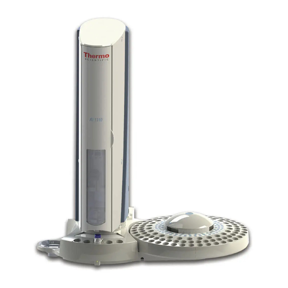
Introduction The AI 1310/AS 1310 Sampling System The AI 1310/AS 1310 Sampling System The 1300 Series Autosampler, available as AI 1310 or AS 1310, consists of the following parts, as respectively shown in Figure 1 Figure Figure 1. AI 1310 Sampling System... - Page 27 Safety Door Injection Unit 105-position Sample Tray or 155-position Sample Tray Base Centering Plate Washing and Waste Tray AS 1310 with 105-position Sample Tray AS 1310 with 155-position Sample Tray Thermo Scientific AI 1310/AS 1310 Sampling System - User Guide...
-
Page 28: Sampling Unit
Sampler Support — Constitutes the supporting base allowing to install the sampler on the gas chromatograph. User Interface — The functions of the AI 1310/AS 1310 can be controlled through: • a data processing system for PC with dedicated software. -
Page 29: Configurations Of The 1310 Series Autosampler
Introduction Configurations of the 1310 Series Autosampler Configurations of the 1310 Series Autosampler The AI 1310/AS 1310 can be installed on the TRACE 1300/TRACE 1310, TRACE GC Ultra, or FOCUS GC gas chromatographs for sample introduction into the following injectors: •... -
Page 30: As 1310 Configuration
Gemini Configuration Consists of the installation of two AI 1310/AS 1310 on the same GC. Note Gemini configuration is not possible with the FOCUS GC. • With the TRACE 1300/TRACE 1310 — the autosamplers are installed on the right side, one on the Front injector module, and the other on the Back injector module. -
Page 31: Installation
Introduction Configurations of the 1310 Series Autosampler Installation The AI 1310/AS 1310 can be installed on the right or left side of the GC according to the following indications: Right Configuration The right configuration is the default configuration for all the TRACE 1300/TRACE 1310, TRACE GC Ultra, and FOCUS GC units. -
Page 32: Technical Specifications
Introduction Technical Specifications Gemini Configuration Two AI 1310/AS 1310 are installed on the same TRACE 1300, TRACE 1310, or TRACE GC Ultra by using their own dedicated supports. Refer to “Sampling System Support” page Technical Specifications Technical specification of the AI 1310/AS 1310 are listed in Table Table 1. - Page 33 290 x 470 x 400 mm (D x W x H) Mass • AI Configuration: approx. 6 kg • AS Configuration with 105-position sample tray: approx. 6 kg • AS Configuration with 155-position sample tray: approx. 7 kg Thermo Scientific AI 1310/AS 1310 Sampling System - User Guide...
-
Page 35: Chapter 2 Sampling Unit
AI 1310/AS 1310 system. Contents • Base • Turret • Injection Assembly • Washing and Waste Tray • Back of the Sampling Unit • Sample Trays • Centering Plate • Status LED Thermo Scientific AI 1310/AS 1310 Sampling System - User Guide... -
Page 36: Base
• Back Section — Includes the connections of the instrument to the mains, the gas chromatograph, the data system and the sample tray (only for AS 1310), and the connection for the Gemini configuration. AI 1310/AS 1310 Sampling System - User Guide Thermo Scientific... -
Page 37: Turret
The front side is provided with a safety door for accessing to the injection assembly. The door opening immediately cuts off the power supply to the sampling system. Figure 8. The Turret Safety Door Thermo Scientific AI 1310/AS 1310 Sampling System - User Guide... -
Page 38: Injection Assembly
The travel ends of the movable parts are defined by a series of sensors. Inside the turret there are also two electronic boards: one for the motors control and one for the instrument functions control, respectively. AI 1310/AS 1310 Sampling System - User Guide Thermo Scientific... -
Page 39: Vial Capture Device
A thorough washing of the syringe can be done thanks to the possibility of using up to four solvents. See Washing and Waste Tray. To install or replace the syringe, please see the Chapter 3, “Installation,” and the Chapter 5, “Maintenance.” Figure 11 shows the syringe housing. Thermo Scientific AI 1310/AS 1310 Sampling System - User Guide... -
Page 40: Turret Movements
• Sample injection — The turret positions itself on the injector to perform the sample injection. • Syringe washing — The turret positions itself on the solvents vials for the syringe washing. The solvent is automatically withdrawn and discharged into the waste container. AI 1310/AS 1310 Sampling System - User Guide Thermo Scientific... -
Page 41: Washing And Waste Tray
Back of the Sampling Unit The back side of the sampling unit includes the following components. See Figure Figure 13. Back of the Sampling Unit TWIN SYNC TRAY RS 232 24 Vdc Thermo Scientific AI 1310/AS 1310 Sampling System - User Guide... -
Page 42: Sample Trays
AI 1310/AS 1310 installed in Gemini configuration through the proper cable. Sample Trays The AI 1310/AS 1310 can accept three types of sample trays which are accommodated in one of the two side housings on the base. The type of sample tray accessory installed on the instrument (8, 105, or 155 positions) is automatically acknowledged by the sampler when powered on determining the instrument configuration. -
Page 43: 105-Position Sample Tray Assembly
The rotation of the tray is accomplished by a motor, located under the supporting plate, which actuates the hub thanks to suitable commands coming from the sampling unit via an interfacing cable. An optical sensor defines the rotation travel end and the vial position. Thermo Scientific AI 1310/AS 1310 Sampling System - User Guide... -
Page 44: Vials
Centering Plate for TRACE 1300/TRACE 1310 The centering plate is provided with two circular guides to center the sampling unit on the SSL, SSLBKF, PTV and PTVBKF injector nuts. AI 1310/AS 1310 Sampling System - User Guide Thermo Scientific... - Page 45 Figure 17. Circular Guide for SSL and SSLBKF CAUTION The circular guide for SSL and SSLBKF placed in the centering plate must be aligned as shown below: CORRECT WRONG Figure 18. Circular Guide for PTV and PTVBKF Thermo Scientific AI 1310/AS 1310 Sampling System - User Guide...
-
Page 46: Centering Plate For Trace Gc Ultra And Focus Gc
Figure 20, provides the operator with indications on the instrument operating conditions showing a continuous or intermittent light. See Table 2 for details. Figure 20. The Status LED Status LED AI 1310/AS 1310 Sampling System - User Guide Thermo Scientific... - Page 47 Two beep monotone; 0.5 seconds ON, 0.5 seconds OFF, 0.5 seconds ON indicates that the start signal is received. Five consecutive beep, 1 second with interval of 0.5 seconds OFF in case of error condition. Thermo Scientific AI 1310/AS 1310 Sampling System - User Guide...
-
Page 49: Chapter 3 Installation
Installation This chapter contains the instructions for the installation of the AI 1310/AS 1310 on the TRACE 1300/TRACE 1310, TRACE GC Ultra, and FOCUS GC gas chromatographs, the syringe, and the electrical connections with the different units of the gas chromatographic system. -
Page 50: Who Performs The Installation
Poor grounding represents a danger for the operator and may seriously affect the instrument performance. Do not connect the AI 1310/AS 1310 to lines feeding devices of a heavy duty nature, such as motors, UV lamps, refrigerators and other devices that can generate disturbances. -
Page 51: Sampling System Support
Sampling System Support for TRACE 1300/TRACE 1310 The AI 1310/AS 1310 can be installed only on the right side of the GC on the front or back injector module or on both when in Gemini configuration by using the proper sampling system support. - Page 52 Figure 23. Support Oriented for the Installation on the Back Injector Module Guide Pivot Retainer Top Plate Retainer Support Pin (Only for AS 1310) Sliding Slot L-shape Bottom Plate (Oriented on Back) AI 1310/AS 1310 Sampling System - User Guide Thermo Scientific...
- Page 53 CAUTION: The AS 1310 equipped with the 155-position sample tray can ONLY be mounted on the front injector module. The back top plate is not provided with the 155-position sample tray. Thermo Scientific AI 1310/AS 1310 Sampling System - User Guide...
-
Page 54: Sampling System Support For Trace Gc Ultra
Sampling System Support for TRACE GC Ultra The support for the installation of the AI 1310/AS 1310 on right or left side of the TRACE GC Ultra consists of a semi-circular plate resting on three spacers non adjustable in height; see Figure 26. - Page 55 Installation Sampling System Support Figure 27. Bracket for the Installation of the AI 1310/AS 1310 Support 1 = Support Bracket 2 = Holes on the TRACE GC Ultra Top Cover 3 = Fixing Screws 4 = Sampling Unit Support CAUTION If you are installing the sampling system support for the installation of an AS1310 equipped with the 155-position sample tray, make sure that the support pin is screwed into the dedicated hole on the sampling system support.
-
Page 56: Sampling System Support For Focus Gc
Installation Sampling System Support Sampling System Support for FOCUS GC The support for the installation of the AI 1310/AS 1310 on the right side of the FOCUS GC, consists of two semi-circular plates. See Figure 28. The top surface of the upper plate is provided with two slots for corresponding fixing screws. -
Page 57: Installing The Sampling System Support On The Trace 1300/1310 Gc
Installation Holes for the AI 1310/AS 1310 on the Front Injector Module. Assembling of the Sampling System Support on the Back Injector Module Installation Holes for Two AI 1310/AS 1310 in Gemini Configuration. Assembling of the Sampling System Support for the Gemini Configuration... -
Page 58: Module
2. Orient the L-shape bottom plate to align the three installation holes to the corresponding fixing holes located on the GC top. 3. Insert the provided fixing screws into the holes present on the L-shape bottom plate. AI 1310/AS 1310 Sampling System - User Guide Thermo Scientific... - Page 59 11. If you must install an AS 1310, screw the support pin into the dedicated hole on the top plate. Note The support pin is NOT required if you must install an AI 1310. Thermo Scientific AI 1310/AS 1310 Sampling System - User Guide...
-
Page 60: Module
2. Orient the L-shape bottom plate to align the three installation holes to the corresponding fixing holes located on the GC top. 3. Insert the provided fixing screws into the holes present on the L-shape bottom plate. AI 1310/AS 1310 Sampling System - User Guide Thermo Scientific... - Page 61 11. If you must install an AS 1310, screw the support pin into the dedicated hole of the top plate. Note The support pin is NOT required if you must install an AI 1310. Thermo Scientific AI 1310/AS 1310 Sampling System - User Guide...
-
Page 62: Assembling Of The Sampling System Support For The Gemini Configuration
Assembling of the Sampling System Support for the Gemini Configuration The following is the description of how to mount the sampling system support on the TRACE 1300/TRACE 1310 for the installation of two AI 1310/AS 1310 sampling systems in Gemini configuration. See... - Page 63 10. If you must install an AS 1310, screw the support pin into the dedicated hole of each top plate. Note The support pin is NOT required if you must install an AI 1310. Thermo Scientific AI 1310/AS 1310 Sampling System - User Guide...
-
Page 64: Assembling Of The Sampling System Support When A Tsq Quantum Is Coupled With The Gc
The following is the description of how to mount the sampling system support on the TRACE 1300/TRACE 1310 for the installation of one or two AI 1310/AS 1310 sampling systems when a TSQ Quantum mass spectrometer is coupled with the GC. See... - Page 65 L-shape bottom plate. 9. Screw the support pin into the dedicated hole of each top plate. Note The support pin is NOT required if you must install an AI 1310. Thermo Scientific AI 1310/AS 1310 Sampling System - User Guide...
-
Page 66: Installing The Sampling System Support On The Trace Gc Ultra
Figure 38. Installation of the Spacer Inside the GC 1. Remove the cover and the collar of the injector and detector compartment. 2. Open the column oven door. Loosen the two knobs located in the upper parts. AI 1310/AS 1310 Sampling System - User Guide Thermo Scientific... -
Page 67: Assembling Of The Sampling System Support On The Gc Right Side
7. If you must install an AS 1310 equipped with the 155-position sampler tray, screw the support pin into the dedicated hole on the sampling system support. Support Pin Note The support pin is NOT required if you must install an AI 1310. Thermo Scientific AI 1310/AS 1310 Sampling System - User Guide... -
Page 68: Assembling Of The Sampling System Support On The Gc Left Side
Support Pin Note The support pin is NOT required if you must install an AI 1310. Installing the Sampling System Support on the FOCUS GC To install the support on the FOCUS GC, please refer to the instructions reported below. -
Page 69: Assembling Of The Sampling System Support On The Gc Right Side
3 = Left Side Fixing Holes 4 = Support Positioning Proceed as follows: 1. Remove from the GC upper cover the two internal plastic caps covering the corresponding fixing holes. See Figure Thermo Scientific AI 1310/AS 1310 Sampling System - User Guide... -
Page 70: Space Saving Installation
This type of installation is suggested to reduce the working area of your FOCUS GC equipped with the AS 1310. This is applicable for example when two or more FOCUS GC units are to be placed on the same workbench. See Figure AI 1310/AS 1310 Sampling System - User Guide Thermo Scientific... - Page 71 2. Insert into each slot present on the support the provided fixing screw. 3. Guide the two fixing screws into the corresponding fixing holes located on the GC upper panel. 4. Loosely tighten the screws. Thermo Scientific AI 1310/AS 1310 Sampling System - User Guide...
-
Page 72: Installation Of The Ai 1310/As 1310 On The Gc
Installation of the AI 1310/AS 1310 on the GC Installation of the AI 1310/AS 1310 on the GC To install the AI 1310/AS 1310 on the TRACE 1300/TRACE 1310, TRACE GC Ultra, and FOCUS GC gas chromatographs, please refer to the instructions reported below: The procedure includes the following steps: •... - Page 73 3. Check the correct alignment of the sampling system support, then fix it by tightening the proper fixing screws. 4. Insert the sample tray into the sampling unit base. • AI 1310 — Insert the 8-position sample tray into the appropriate housing of the sampling unit base. See Figure Figure 45.
- Page 74 Installation Installation of the AI 1310/AS 1310 on the GC • AS 1310 — According to the AS 1310 with the 105 or 155-position sample tray, insert the dedicated support plate into its appropriate housing of the sampling unit base. Place the sample tray on the hub located on the support. The system will automatically recognize the sample tray at the instrument power on.
-
Page 75: Installation Of The Syringe
Installation Installation of the AI 1310/AS 1310 on the GC Installation of the Syringe To install the syringe follow the instructions reported below. The installation of the syringe is a simple operation. However, it must be performed with caution to avoid damages to the syringe needle and ensure an optimal performance of the injection device. -
Page 76: Electrical Connections
“Electrical Requirements” page 26 have been fulfilled. This section provides the instruction to connect the AI 1310/AS 1310, in standard o Gemini configuration, to a TRACE 1300/TRACE 1310, TRACE GC Ultra, or FOCUS GC. Refer to: •... - Page 77 This section provides instructions for connecting two AI 1310/AS 1310 in Gemini Configuration. In Gemini configuration, the AI 1310/AS 1310 autosamplers can work in three operating mode: • High Throughput Mode — Processes large batches of samples with the same analytical conditions and double the system productivity.
- Page 78 Installation Installation of the AI 1310/AS 1310 on the GC Figure 49. Gemini Configuration Cables Connections - HWSetup 1 AI/AS 1310 (a) AI/AS 1310 (b) TWIN TWIN SYNC SYNC RS 232 RS 232 TR AY TR AY 24 Vdc 24 Vdc...
- Page 79 HWSetup 1 Figure 49 Figure 49 Figure 49 The unplugging of the power cord from the unused AI 1310/AS 1310 autosampler could be required Not Applicable To perform the HWSetup 1 of two AI/AS 1310 in Gemini Configuration 1. Using the cable provided (PN 23043672), connect the 4-pin male connector marked TWIN SYNC, on the back of the sampling unit of the sampler “a”, to the 4-pin male...
-
Page 80: Instrument Start-Up
24 Vdc located on the sampling unit back side. 2. Connect the power cord of the external power supply to the mains outlet. The AI 1310/AS 1310 will automatically run the self-testing routine during which the following automatic checks and settings are carried out: •... -
Page 81: Chapter 4 Ai 1310/As 1310 Control
AI 1310/AS 1310 Control This chapter provides the information for controlling the AI 1310/AS 1310 through the Chromatography Data System, or the TRACE GC Ultra, or the FOCUS GC. The chapter contains also the working procedures with different injectors. Contents •... -
Page 82: Control Through The Chromatography Data System
Chromeleon CDS Xcalibur, Chrom-Card, ChromQuest CDS CAUTION Configuring the AI 1310/AS 1310 through the GC may slow down the communication performance, since a large amount of data is sent to TRACE 1300/1310 GC, and then the GC sends to AI 1310/AS 1310. -
Page 83: Chromeleon Cds User Interface
This page is shown in Figure Figure 51. AI 1310/AS 1310 Autosampler Chromeleon CDS User Interface Edit the autosampler method using the following parameters: Air Volume — Specifies the volume of air drawn after pulling the syringe needle out of the vial. - Page 84 Connect — Connects the autosampler to the data system. Disconnect — Disconnects the autosampler from the data system. Clean — (obsolete AI/AS 1310 drivers only) Cleans the syringe in combination with the washing parameters. AI 1310/AS 1310 Sampling System - User Guide Thermo Scientific...
-
Page 85: Xcalibur, Chrom-Card, And Chomquest Cds User Interface
This page is shown in Figure Figure 52. AI 1310/AS 1310 Autosampler Xcalibur, Chrom-Card, ChromQuest CDS User Interface Edit the autosampler method using the following parameters: Sample Volume — Enter a value for the injection volume. The range depends on the size of syringe selected in the Instrument Configuration. - Page 86 The following commands are available: Get Method from Sampler — Transfer the AI 1310/AS 1310 current method to the GC. Send Method to Sampler — Transfers the method from the computer to the a AI 1310/AS 1310 and makes the method active.
-
Page 87: Messages
• The AI 1310/AS 1310 is in stand-by • AI 1310/AS 1310 is checking positions • AI 1310/AS 1310 ready to inject sample in vial n but waiting GC Ready • AI 1310/AS 1310 is preparing the sample in vial n. -
Page 88: Configuring The Ai 1310/As 1310
Note Should the AI 1310/AS 1310 not be installed or correctly connected, the TRACE GC Ultra will display the message NO AUTOSAMPLER INSTALLED. AI 1310/AS 1310 Menu To set the parameters of the AI 1310/AS 1310 method, press Autosampler key to open the relevant menu described in Table Table 4. -
Page 89: Extended Control Menu
This parameter defines the speed at which the sample is drawn from the vial as a function of the sample viscosity. Select No (default value) if the sample has low viscosity. Select Yes if the sample has high viscosity. Thermo Scientific AI 1310/AS 1310 Sampling System - User Guide... -
Page 90: When No Vial Abort Menu
If this function is selected, the sequence is aborted after a missing vial. Control Through the FOCUS GC This paragraph describes how to program and control the AI 1310/AS 1310 through the FOCUS GC keypad. CAUTION The FOCUS GC does not control the AS 1310 with the 155-position sample tray. -
Page 91: Configuring The Ai 1310/As 1310
Sample tray is not editable. AI 1310/AS 1310 Menu To set the parameters of the AI 1310/AS 1310 method, In Main Menu move the cursor until Autosampler is displayed, then press Enter to open the menu. See Table 7 for details. - Page 92 (Hot Needle Technique). Post dwell time 0–63 sec This parameter specifies how long the syringe needle must remain inside the injector after injection. AI 1310/AS 1310 Sampling System - User Guide Thermo Scientific...
-
Page 93: Sequence Of Samples With The As 1310
If this function is selected, the sequence is aborted after a missing vial. Guidelines for Programming with Different Injectors To get the best results from your AI 1310/AS 1310, follow these guidelines when programming the sampler method according to the injector in use: •... -
Page 94: Ssl Inlet (Trace 1300/1310 Gc)
Guidelines for Programming with Different Injectors SSL Inlet (TRACE 1300/1310 GC) The AI 1310 /AS 1310 injects into the SSL inlet using the liquid band technique. The needle penetrates for almost its whole length without pre- and post-dwell time in order to avoid any possible heating, still injecting deep into the liner. -
Page 95: Ssl Inlet (Trace Gc Ultra/Focus Gc)
SSL Inlet (TRACE GC Ultra/FOCUS GC) The AI 1310/AS 1310 can inject in a hot SSL inlet using two distinct needle insertion modes: “Standard” and “Minimum”. • In Standard mode the needle penetrates for almost its whole length and a dwell time is programmed to provide needle heating. - Page 96 Injection depth = Minimum Pre and Post Inject Delay Time = 0 s (Chromeleon CDS) Pre and Post Injection Dwell Time are automatically inhibited (Xcalibur, ChromCard, ChomQuest CDS) Only with 0.5μL syringe. AI 1310/AS 1310 Sampling System - User Guide Thermo Scientific...
- Page 97 The reduction of the injection volume to the sub microliter range using a standard sampler, like the AI 1310/AS 1310 unit, is achievable by exploiting the low capacity syringe (0.5 μL) and the tapered liner. High accuracy and repeatability injecting nano-volumes are achievable by exploiting the “Cold Needle”...
-
Page 98: Ssl Inlet With A Merlin Microseal™ (Trace Gc Ultra Only)
2. Enter the Injector menu and switch off the inlet temperature. 3. Enter Carrier Menu and switch off the carrier supply. 4. Remove the centering plate of the AI 1310/AS 1310 (if installed). 5. Wait till the injector has reached room temperature and by means of the outfit tool unscrew the septum cap, then remove it together with the septum holder and its plate. -
Page 99: Ptv Inlet (Trace 1300/1310 Gctrace Gc Ultra)
Injection depth = Standard Vaporizing Injector (PTV) Pre and Post Inject Delay Time = 1-2 s (Chromeleon CDS) Pre and Post Injection Dwell Time = 1-2 s (Xcalibur, Chrom-Card, ChromQuest CDS) Thermo Scientific AI 1310/AS 1310 Sampling System - User Guide... -
Page 100: Ptv Inlet With A Merlin Microseal
Pre Inject Delay Time = 3-5 s Post Inject Delay Time = 0 s (Chromeleon CDS) Pre Injection Dwell Time = 3-5 s Post Injection Dwell Time = 0 s (Xcalibur, Chrom-Card, ChromQuest CDS) AI 1310/AS 1310 Sampling System - User Guide Thermo Scientific... -
Page 101: Chapter 5 Maintenance
Maintenance This chapter provides guidelines for the maintenance of the AI 1310/AS 1310. Contents • Current Maintenance • Emptying of the Waste Container • Cleaning of the Sample Tray Accessory • Cleaning the Instrument Externally • Replacing the Syringe •... -
Page 102: Current Maintenance
Current Maintenance Current Maintenance The AI 1310/AS 1310 does not generally require maintenance, except emptying of the waste container when full, cleaning of the sample tray and replacement of the syringe. For any other operation, contact Thermo Fisher Scientific Technical Service. -
Page 103: Replacing The Syringe
7. Accommodate the syringe body into its seat, paying attention to simultaneously introduce the syringe plunger flange and head into their relevant guides. 8. Lock the syringe by turning the lock wheel by 180° clockwise. Thermo Scientific AI 1310/AS 1310 Sampling System - User Guide... -
Page 104: Cleaning The Syringe
1. Fill a 4 mL vial with fresh solvent with high cleaning power (acetone is recommended) and place it in the D position of the washing tray of the AI 1310/AS 1310. 2. From your PC, enter the Data System and then access the AI 1310/AS 1310 method page. -
Page 105: Manual Cleaning
1. Fill a 4 mL vial with fresh solvent (hexane is recommended) and place it in the D position of the washing tray of the AI 1310/AS 1310. 2. From your PC, enter the Data System and then access the AI 1310/AS 1310 method page. Select the following parameters: •... -
Page 106: Moving Away The Sampling Unit From The Injector Module
6. Reinsert the centering plate into its seat of the sampling unit base paying attention that the guide hole, present on the arm of the centering plate, correctly fits the injector nut. 7. Reinsert the sample tray into its seat of the sampling unit base. AI 1310/AS 1310 Sampling System - User Guide Thermo Scientific... -
Page 107: Glossary
°C Celsius FSE Field Service Engineer CIP Carriage and Insurance Paid To ft foot cm centimeter CPU central processing unit (of a computer) g gram <Ctrl> control key of the keyboard Thermo Scientific AI 1310/AS 1310 Sampling System - User Guide... - Page 108 PTV Programmable Temperature Vaporizing Injector l length L liter RAM random access memory LAN Local Area Network <Return> <Return> key on the lb pound keyboard AI 1310/AS 1310 Sampling System - User Guide Thermo Scientific...
- Page 109 50 μs. V volt V ac volts, alternating current V dc volts, direct current VGA Video Graphics Array w width W Watt Thermo Scientific AI 1310/AS 1310 Sampling System - User Guide...
-
Page 111: Index
TRACE 1300/TRACE 1310 External interface for FOCUS GC Cleaning Instrument Sample Tray feedback Syringe First sample Command Menu Flushing solvents Configuration FOCUS GC AI 1310 AI 1310/AS 1310 Menu AS 1310 Thermo Scientific AI 1310/AS 1310 Sampling System - User Guide... - Page 112 5, 6, Packing a SSL Liner Parameters Help Menu Injection How to Configure the Autosampler Sampling How to Install the AI 1310 on the GC Washes PKD Inlet Plunger strokes Post dweel time Important Information Post wash cycles Inj. depth...
- Page 113 Waste container capacity Sample Trays When no vial Status LED Turret Vial Capture Device Washing Tray Waste Tray Sequence of Samples with the AS 1310 Autosampler Signal Words SSL Inlet Thermo Scientific AI 1310/AS 1310 Sampling System - User Guide...
Need help?
Do you have a question about the AI 1310 and is the answer not in the manual?
Questions and answers