Table of Contents
Advertisement
Quick Links
- 1 Signals ꞏꞏꞏꞏꞏꞏꞏꞏꞏꞏꞏꞏꞏꞏꞏꞏꞏꞏꞏꞏꞏꞏꞏꞏꞏꞏꞏꞏꞏꞏꞏꞏꞏꞏꞏꞏꞏꞏꞏꞏꞏꞏꞏꞏꞏꞏꞏꞏꞏꞏꞏꞏꞏꞏꞏꞏꞏꞏꞏꞏꞏꞏꞏꞏꞏꞏꞏꞏꞏꞏꞏꞏꞏꞏꞏꞏꞏꞏꞏꞏꞏꞏꞏꞏꞏꞏꞏꞏꞏꞏꞏꞏꞏꞏꞏꞏꞏꞏꞏꞏꞏꞏꞏꞏꞏꞏꞏꞏꞏꞏꞏꞏꞏꞏꞏꞏꞏꞏꞏ
- 2 Parameters ꞏꞏꞏꞏꞏꞏꞏꞏꞏꞏꞏꞏꞏꞏꞏꞏꞏꞏꞏꞏꞏꞏꞏꞏꞏꞏꞏꞏꞏꞏꞏꞏꞏꞏꞏꞏꞏꞏꞏꞏꞏꞏꞏꞏꞏꞏꞏꞏꞏꞏꞏꞏꞏꞏꞏꞏꞏꞏꞏꞏꞏꞏꞏꞏꞏꞏꞏꞏꞏꞏꞏꞏꞏꞏꞏꞏꞏꞏꞏꞏꞏꞏꞏꞏꞏꞏꞏꞏꞏꞏꞏꞏꞏꞏꞏꞏꞏꞏꞏꞏꞏꞏꞏꞏꞏꞏꞏꞏꞏꞏꞏꞏꞏ
- 3 Alarm Occurrence Timing Chart
- 4 Alarm Mode ꞏꞏꞏꞏꞏꞏꞏꞏꞏꞏꞏꞏꞏꞏꞏꞏꞏꞏꞏꞏꞏꞏꞏꞏꞏꞏꞏꞏꞏꞏꞏꞏꞏꞏꞏꞏꞏꞏꞏꞏꞏꞏꞏꞏꞏꞏꞏꞏꞏꞏꞏꞏꞏꞏꞏꞏꞏꞏꞏꞏꞏꞏꞏꞏꞏꞏꞏꞏꞏꞏꞏꞏꞏꞏꞏꞏꞏꞏꞏꞏꞏꞏꞏꞏꞏꞏꞏꞏꞏꞏꞏꞏꞏꞏꞏꞏꞏꞏꞏꞏꞏꞏꞏꞏꞏꞏꞏꞏꞏꞏꞏꞏꞏꞏꞏ
- Download this manual
Advertisement
Table of Contents

Related Manuals for Mitsubishi Electric MELSERVO-JN Series


Summary of Contents for Mitsubishi Electric MELSERVO-JN Series
- Page 1 General-Purpose AC Servo JN Series General-Purpose Interface Servo Amplifier MODEL (Servo Amplifier) MR-JN-□A MODEL (Servo Motor) HF-KN□ HF-KP□G1/G5/G7 HG-KR□G1/G5/G7 INSTRUCTION MANUAL...
- Page 2 Safety Instructions Please read the instructions carefully before using the equipment. Be sure to read through this Instruction Manual, Installation guide and appended documents carefully before using the equipment. For your protection, do not install, operate, inspect or perform maintenance procedures until you have a full knowledge of the equipment and the safety information and instructions.
- Page 3 1. To prevent electric shock, note the following WARNING Before wiring, be sure to turn off the power, wait for 15 minutes or longer, and then make sure that the charge lamp is off to prevent an electric shock. In addition, always confirm if the charge lamp is off or not from the front of the servo amplifier.
- Page 4 4. Additional instructions The following instructions should also be fully noted. Incorrect handling may cause a fault, injury, electric shock, etc. (1) Transportation and installation CAUTION Carry the products in a suitable way according to their weights. Do not stack the product packages exceeding the maximum number specified on the package. Do not hold the lead of the built-in regenerative resistor, the cables, or the connectors when carrying the servo amplifier.
-
Page 5: Signals ꞏꞏꞏꞏꞏꞏꞏꞏꞏꞏꞏꞏꞏꞏꞏꞏꞏꞏꞏꞏꞏꞏꞏꞏꞏꞏꞏꞏꞏꞏꞏꞏꞏꞏꞏꞏꞏꞏꞏꞏꞏꞏꞏꞏꞏꞏꞏꞏꞏꞏꞏꞏꞏꞏꞏꞏꞏꞏꞏꞏꞏꞏꞏꞏꞏꞏꞏꞏꞏꞏꞏꞏꞏꞏꞏꞏꞏꞏꞏꞏꞏꞏꞏꞏꞏꞏꞏꞏꞏꞏꞏꞏꞏꞏꞏꞏꞏꞏꞏꞏꞏꞏꞏꞏꞏꞏꞏꞏꞏꞏꞏꞏꞏꞏꞏꞏꞏꞏꞏ
CAUTION The servo amplifier must be installed in the metal cabinet. When fumigants that contain halogen materials such as fluorine, chlorine, bromine, and iodine are used for disinfecting and protecting wooden packaging from insects, they cause malfunction when entering our products. - Page 6 (4) Usage CAUTION Configure an external emergency stop circuit in order to stop the operation immediately and shut off the power. Do not disassemble or repair the equipment. If an alarm is reset while the operation signal is input to the servo amplifier, the equipment starts suddenly.
- Page 7 (6) Storing of servo motor CAUTION Note the following points when storing the servo motor for an extended period of time (guideline: three or more months). Be sure to store the servo motor indoors in a clean and dry place. If it is stored in a dusty or damp place, make adequate provision, e.g.
-
Page 8: Parameters ꞏꞏꞏꞏꞏꞏꞏꞏꞏꞏꞏꞏꞏꞏꞏꞏꞏꞏꞏꞏꞏꞏꞏꞏꞏꞏꞏꞏꞏꞏꞏꞏꞏꞏꞏꞏꞏꞏꞏꞏꞏꞏꞏꞏꞏꞏꞏꞏꞏꞏꞏꞏꞏꞏꞏꞏꞏꞏꞏꞏꞏꞏꞏꞏꞏꞏꞏꞏꞏꞏꞏꞏꞏꞏꞏꞏꞏꞏꞏꞏꞏꞏꞏꞏꞏꞏꞏꞏꞏꞏꞏꞏꞏꞏꞏꞏꞏꞏꞏꞏꞏꞏꞏꞏꞏꞏꞏꞏꞏꞏꞏꞏꞏ
Write to the EEP-ROM due to data records with drive recorder Precautions for Choosing the Products Mitsubishi Electric will not be held liable for damage caused by factors found not to be the cause of Mitsubishi Electric; machine damage or lost profits caused by faults in the Mitsubishi Electric products;... - Page 9 <<About the manuals>> Relevant manuals Manual name Manual No. MELSERVO-JN Series Instructions and Cautions for Safe Use of AC Servos IB(NA)0300157 (Enclosed in servo amplifier.) QUICK INSTALLATION GUIDE L(NA)03052ENG MELSERVO Servo Motor Instruction Manual Vol.2 SH(NA)030041ENG MELSERVO Servo Motor Instruction Manual Vol.3...
- Page 10 For details of functions, performance and specifications of the MELSERVO-JN series, refer to chapters 1 to 13 and appendices of this Instruction Manual. This section describes the how-to (startup, actual operation, and others) for users who use the MELSERVO-JN series AC servo for the first time.
- Page 11 Introduction 1. Operation and setting Operation and settings of the servo amplifier are easily performed only on the display section (3-digit, 7- segment LED) and on the operation section (four pushbuttons and one-touch tuning button) located on the front panel of the servo amplifier. AUTO Executes the one-touch tuning.
- Page 12 Introduction 2. Startup When switching the power on for the first time, follow the startup procedure below. Refer to (1) in this section. Visual wiring check Surrounding environment Check the surrounding environment (cable routing and check impurity such as wire offcuts or metallic dust) of the servo amplifier and the servo motor.
-
Page 13: Introduction ꞏꞏꞏꞏꞏꞏꞏꞏꞏꞏꞏꞏꞏꞏꞏꞏꞏꞏꞏꞏꞏꞏꞏꞏꞏꞏꞏꞏꞏꞏꞏꞏꞏꞏꞏꞏꞏꞏꞏꞏꞏꞏꞏꞏꞏꞏꞏꞏꞏꞏꞏꞏꞏꞏꞏꞏꞏꞏꞏꞏꞏꞏꞏꞏꞏꞏꞏꞏꞏꞏꞏꞏꞏꞏꞏꞏꞏꞏꞏꞏꞏꞏꞏꞏꞏꞏꞏꞏꞏꞏꞏꞏꞏꞏꞏꞏꞏꞏꞏꞏꞏꞏꞏꞏꞏꞏꞏꞏꞏꞏꞏꞏꞏꞏ
Introduction (1) Visual wiring check Before switching on the main circuit and control circuit power supplies, check the following items. Power supply system wiring The power supplied to the power input terminals (L , +24V, 0V) of the servo amplifier should satisfy the defined specifications. - Page 14 Introduction (2) Power on and off procedures (a) Power-on Switch the power on in the following procedure. Always follow this procedure at power-on. 1) Turn off the servo-on (SON). 2) Make sure that command and start signal from the controller are not input. 3) Switch on the control circuit power supply.
-
Page 15: Parameters ꞏꞏꞏꞏꞏꞏꞏꞏꞏꞏꞏꞏꞏꞏꞏꞏꞏꞏꞏꞏꞏꞏꞏꞏꞏꞏꞏꞏꞏꞏꞏꞏꞏꞏꞏꞏꞏꞏꞏꞏꞏꞏꞏꞏꞏꞏꞏꞏꞏꞏꞏꞏꞏꞏꞏꞏꞏꞏꞏꞏꞏꞏꞏꞏꞏꞏꞏꞏꞏꞏꞏꞏꞏꞏꞏꞏꞏꞏꞏꞏꞏꞏꞏꞏꞏꞏꞏꞏꞏꞏꞏꞏꞏꞏꞏꞏꞏꞏꞏꞏꞏꞏꞏꞏꞏꞏꞏꞏꞏꞏ
Introduction The following shows the main parameters, which must be changed, among parameter No. PA PA01 Selection of control mode (refer to section 4.1.3) Select the control mode of the servo amplifier, and whether to enable or not the one-touch tuning function. Parameter No. - Page 16 Introduction PA13 Selection of command input pulse form (refer to section 4.1.11) Select the input form of the pulse train input signal. Command pulses may be input in any of three different forms, for which positive or negative logic can be chosen. Arrow in the table indicates the timing of importing a pulse train.
- Page 17 Introduction PA14 Selection of servo motor rotation direction (refer to section 4.1.12) Select servo motor rotation direction relative to the input pulse train. Servo motor rotation direction Parameter No. PA14 setting When forward rotation pulse is input When reverse rotation pulse is input Forward rotation (CCW) Reverse rotation (CW) (5) Operation confirmation before actual operation...
- Page 18 Introduction (6) One-touch tuning Just by pressing the "AUTO" button on the front panel of the servo amplifier during operation, the gain/filter is easily adjusted. (Refer to section 6.1.) Startup of system Rotate the servo motor by a command device, etc. Operation (The one-touch tuning cannot be performed if the servo motor is not operating.)
- Page 19 Introduction (7) Stop In any of the following statuses, the servo amplifier interrupts and stops the operation of the servo motor. Refer to section 3.11 for the servo motor with an electromagnetic brake. (a) Servo-on (SON) OFF The base circuit is shut off and the servo motor coasts. (b) Alarm occurrence When an alarm occurs, the base circuit is shut off and the dynamic brake activates to stop the servo motor immediately.
- Page 20 Introduction 3. Troubleshooting at startup Never adjust or change the parameter values extremely as it will make operation CAUTION unstable. POINT You can refer to reasons for servo motor rotation failure, etc. using MR Configurator. The following faults may occur at startup. If any of such faults occurs, take the corresponding action. (1) Troubleshooting Step of occurrence Fault...
- Page 21 Introduction № Step of occurrence Fault Investigation Possible cause Reference Input command Servo motor rotates in Check the cumulative command 1. Mistake in wiring to controller. Section pulse. reverse direction. pulses on the status display or on 2. Mistake in setting of parameter 4.1.12 (Test operation) MR Configurator.
- Page 22 Introduction (2) How to find the cause of position shift Controller Servo amplifier Machine (a)Output pulse Electronic gear (parameters No. PA06, PA07) counter Servo motor (d) Machine stop position M FBP conversion (b)Cumulative command pulses Cause B Cause A Servo-on (SON), Stroke end (LSP/LSN) input Encoder...
- Page 23 Introduction Servo motor encoder resolution 2) When P FBP (parameter No. PA05) (Note) ≠ C CDV Note. When "0" is set to the FBP (parameter No. PA05), the FBP becomes the servo motor encoder resolution. During the operation, the servo-on (SON), the forward/reverse rotation stroke end (LSP/LSN) was turned off, or the clear (CR) or the reset (RES) was turned on.
- Page 24 Introduction (1) Overload tough drive function This function reduces the effective load ratio before an overload alarm occurs to avoid the alarm. (2) Vibration tough drive function This function suppresses the machine resonance caused by aging distortion or individual difference of the machine.
-
Page 25: Table Of Contents
CONTENTS 1. FUNCTIONS AND CONFIGURATION 1 - 1 to 1 -12 1.1 Introduction ............................... 1 - 1 1.2 Function block diagram ..........................1 - 3 1.3 Servo amplifier standard specifications ....................1 - 6 1.4 Function list .............................. 1 - 8 1.5 Model code definition .......................... - Page 26 3.11 Servo motor with an electromagnetic brake ꞏꞏꞏꞏꞏꞏꞏꞏꞏꞏꞏꞏꞏꞏꞏꞏꞏꞏꞏꞏꞏꞏꞏꞏꞏꞏꞏꞏꞏꞏꞏꞏꞏꞏꞏꞏꞏꞏꞏꞏꞏꞏꞏꞏꞏꞏꞏꞏꞏꞏꞏꞏꞏꞏꞏꞏꞏꞏꞏꞏꞏꞏꞏꞏꞏꞏꞏꞏꞏꞏꞏꞏ 3 -43 3.11.1 Safety precautions ꞏꞏꞏꞏꞏꞏꞏꞏꞏꞏꞏꞏꞏꞏꞏꞏꞏꞏꞏꞏꞏꞏꞏꞏꞏꞏꞏꞏꞏꞏꞏꞏꞏꞏꞏꞏꞏꞏꞏꞏꞏꞏꞏꞏꞏꞏꞏꞏꞏꞏꞏꞏꞏꞏꞏꞏꞏꞏꞏꞏꞏꞏꞏꞏꞏꞏꞏꞏꞏꞏꞏꞏꞏꞏꞏꞏꞏꞏꞏꞏꞏꞏꞏꞏꞏꞏꞏꞏꞏꞏꞏꞏꞏꞏꞏꞏꞏꞏꞏ 3 -43 3.11.2 Setting ꞏꞏꞏꞏꞏꞏꞏꞏꞏꞏꞏꞏꞏꞏꞏꞏꞏꞏꞏꞏꞏꞏꞏꞏꞏꞏꞏꞏꞏꞏꞏꞏꞏꞏꞏꞏꞏꞏꞏꞏꞏꞏꞏꞏꞏꞏꞏꞏꞏꞏꞏꞏꞏꞏꞏꞏꞏꞏꞏꞏꞏꞏꞏꞏꞏꞏꞏꞏꞏꞏꞏꞏꞏꞏꞏꞏꞏꞏꞏꞏꞏꞏꞏꞏꞏꞏꞏꞏꞏꞏꞏꞏꞏꞏꞏꞏꞏꞏꞏꞏꞏꞏꞏꞏꞏꞏꞏꞏꞏꞏꞏꞏꞏꞏ 3 -43 3.11.3 Timing chartsꞏꞏꞏꞏꞏꞏꞏꞏꞏꞏꞏꞏꞏꞏꞏꞏꞏꞏꞏꞏꞏꞏꞏꞏꞏꞏꞏꞏꞏꞏꞏꞏꞏꞏꞏꞏꞏꞏꞏꞏꞏꞏꞏꞏꞏꞏꞏꞏꞏꞏꞏꞏꞏꞏꞏꞏꞏꞏꞏꞏꞏꞏꞏꞏꞏꞏꞏꞏꞏꞏꞏꞏꞏꞏꞏꞏꞏꞏꞏꞏꞏꞏꞏꞏꞏꞏꞏꞏꞏꞏꞏꞏꞏꞏꞏꞏꞏꞏꞏꞏꞏꞏꞏꞏꞏꞏ 3 -44 3.11.4 Wiring diagrams (HF-KN series • HF-KP G1/G5/G7 • HG-KR G1/G5/G7 servo motor) ꞏꞏꞏꞏꞏ 3 -46 3.12 Grounding ꞏꞏꞏꞏꞏꞏꞏꞏꞏꞏꞏꞏꞏꞏꞏꞏꞏꞏꞏꞏꞏꞏꞏꞏꞏꞏꞏꞏꞏꞏꞏꞏꞏꞏꞏꞏꞏꞏꞏꞏꞏꞏꞏꞏꞏꞏꞏꞏꞏꞏꞏꞏꞏꞏꞏꞏꞏꞏꞏꞏꞏꞏꞏꞏꞏꞏꞏꞏꞏꞏꞏꞏꞏꞏꞏꞏꞏꞏꞏꞏꞏꞏꞏꞏꞏꞏꞏꞏꞏꞏꞏꞏꞏꞏꞏꞏꞏꞏꞏꞏꞏꞏꞏꞏꞏꞏꞏꞏꞏꞏꞏꞏꞏꞏꞏ...
- Page 27 5.6.3 Operation example ꞏꞏꞏꞏꞏꞏꞏꞏꞏꞏꞏꞏꞏꞏꞏꞏꞏꞏꞏꞏꞏꞏꞏꞏꞏꞏꞏꞏꞏꞏꞏꞏꞏꞏꞏꞏꞏꞏꞏꞏꞏꞏꞏꞏꞏꞏꞏꞏꞏꞏꞏꞏꞏꞏꞏꞏꞏꞏꞏꞏꞏꞏꞏꞏꞏꞏꞏꞏꞏꞏꞏꞏꞏꞏꞏꞏꞏꞏꞏꞏꞏꞏꞏꞏꞏꞏꞏꞏꞏꞏꞏꞏꞏꞏꞏꞏꞏꞏꞏꞏ 5 -15 5.7 Parameter mode ꞏꞏꞏꞏꞏꞏꞏꞏꞏꞏꞏꞏꞏꞏꞏꞏꞏꞏꞏꞏꞏꞏꞏꞏꞏꞏꞏꞏꞏꞏꞏꞏꞏꞏꞏꞏꞏꞏꞏꞏꞏꞏꞏꞏꞏꞏꞏꞏꞏꞏꞏꞏꞏꞏꞏꞏꞏꞏꞏꞏꞏꞏꞏꞏꞏꞏꞏꞏꞏꞏꞏꞏꞏꞏꞏꞏꞏꞏꞏꞏꞏꞏꞏꞏꞏꞏꞏꞏꞏꞏꞏꞏꞏꞏꞏꞏꞏꞏꞏꞏꞏꞏꞏꞏꞏꞏꞏꞏ 5 -17 5.7.1 Parameter mode transition ꞏꞏꞏꞏꞏꞏꞏꞏꞏꞏꞏꞏꞏꞏꞏꞏꞏꞏꞏꞏꞏꞏꞏꞏꞏꞏꞏꞏꞏꞏꞏꞏꞏꞏꞏꞏꞏꞏꞏꞏꞏꞏꞏꞏꞏꞏꞏꞏꞏꞏꞏꞏꞏꞏꞏꞏꞏꞏꞏꞏꞏꞏꞏꞏꞏꞏꞏꞏꞏꞏꞏꞏꞏꞏꞏꞏꞏꞏꞏꞏꞏꞏꞏꞏꞏꞏꞏꞏꞏꞏ 5 -17 5.7.2 Operation example ꞏꞏꞏꞏꞏꞏꞏꞏꞏꞏꞏꞏꞏꞏꞏꞏꞏꞏꞏꞏꞏꞏꞏꞏꞏꞏꞏꞏꞏꞏꞏꞏꞏꞏꞏꞏꞏꞏꞏꞏꞏꞏꞏꞏꞏꞏꞏꞏꞏꞏꞏꞏꞏꞏꞏꞏꞏꞏꞏꞏꞏꞏꞏꞏꞏꞏꞏꞏꞏꞏꞏꞏꞏꞏꞏꞏꞏꞏꞏꞏꞏꞏꞏꞏꞏꞏꞏꞏꞏꞏꞏꞏꞏꞏꞏꞏꞏꞏꞏꞏ 5 -18 5.8 External I/O signal display ꞏꞏꞏꞏꞏꞏꞏꞏꞏꞏꞏꞏꞏꞏꞏꞏꞏꞏꞏꞏꞏꞏꞏꞏꞏꞏꞏꞏꞏꞏꞏꞏꞏꞏꞏꞏꞏꞏꞏꞏꞏꞏꞏꞏꞏꞏꞏꞏꞏꞏꞏꞏꞏꞏꞏꞏꞏꞏꞏꞏꞏꞏꞏꞏꞏꞏꞏꞏꞏꞏꞏꞏꞏꞏꞏꞏꞏꞏꞏꞏꞏꞏꞏꞏꞏꞏꞏꞏꞏꞏꞏꞏꞏꞏꞏꞏ 5 -20 5.9 Output signal (DO) forced output ꞏꞏꞏꞏꞏꞏꞏꞏꞏꞏꞏꞏꞏꞏꞏꞏꞏꞏꞏꞏꞏꞏꞏꞏꞏꞏꞏꞏꞏꞏꞏꞏꞏꞏꞏꞏꞏꞏꞏꞏꞏꞏꞏꞏꞏꞏꞏꞏꞏꞏꞏꞏꞏꞏꞏꞏꞏꞏꞏꞏꞏꞏꞏꞏꞏꞏꞏꞏꞏꞏꞏꞏꞏꞏꞏꞏꞏꞏꞏꞏꞏꞏꞏꞏꞏꞏꞏ 5 -23 5.10 Test operation mode ꞏꞏꞏꞏꞏꞏꞏꞏꞏꞏꞏꞏꞏꞏꞏꞏꞏꞏꞏꞏꞏꞏꞏꞏꞏꞏꞏꞏꞏꞏꞏꞏꞏꞏꞏꞏꞏꞏꞏꞏꞏꞏꞏꞏꞏꞏꞏꞏꞏꞏꞏꞏꞏꞏꞏꞏꞏꞏꞏꞏꞏꞏꞏꞏꞏꞏꞏꞏꞏꞏꞏꞏꞏꞏꞏꞏꞏꞏꞏꞏꞏꞏꞏꞏꞏꞏꞏꞏꞏꞏꞏꞏꞏꞏꞏꞏꞏꞏꞏꞏꞏꞏ...
- Page 28 8.2 Remedies for alarms ꞏꞏꞏꞏꞏꞏꞏꞏꞏꞏꞏꞏꞏꞏꞏꞏꞏꞏꞏꞏꞏꞏꞏꞏꞏꞏꞏꞏꞏꞏꞏꞏꞏꞏꞏꞏꞏꞏꞏꞏꞏꞏꞏꞏꞏꞏꞏꞏꞏꞏꞏꞏꞏꞏꞏꞏꞏꞏꞏꞏꞏꞏꞏꞏꞏꞏꞏꞏꞏꞏꞏꞏꞏꞏꞏꞏꞏꞏꞏꞏꞏꞏꞏꞏꞏꞏꞏꞏꞏꞏꞏꞏꞏꞏꞏꞏꞏꞏꞏꞏꞏꞏꞏꞏ 8 - 3 8.3 Remedies for warnings ꞏꞏꞏꞏꞏꞏꞏꞏꞏꞏꞏꞏꞏꞏꞏꞏꞏꞏꞏꞏꞏꞏꞏꞏꞏꞏꞏꞏꞏꞏꞏꞏꞏꞏꞏꞏꞏꞏꞏꞏꞏꞏꞏꞏꞏꞏꞏꞏꞏꞏꞏꞏꞏꞏꞏꞏꞏꞏꞏꞏꞏꞏꞏꞏꞏꞏꞏꞏꞏꞏꞏꞏꞏꞏꞏꞏꞏꞏꞏꞏꞏꞏꞏꞏꞏꞏꞏꞏꞏꞏꞏꞏꞏꞏꞏꞏꞏꞏꞏꞏ 8 -24 9. DIMENSIONS 9 - 1 to 9 - 4 9.1 Servo amplifier ꞏꞏꞏꞏꞏꞏꞏꞏꞏꞏꞏꞏꞏꞏꞏꞏꞏꞏꞏꞏꞏꞏꞏꞏꞏꞏꞏꞏꞏꞏꞏꞏꞏꞏꞏꞏꞏꞏꞏꞏꞏꞏꞏꞏꞏꞏꞏꞏꞏꞏꞏꞏꞏꞏꞏꞏꞏꞏꞏꞏꞏꞏꞏꞏꞏꞏꞏꞏꞏꞏꞏꞏꞏꞏꞏꞏꞏꞏꞏꞏꞏꞏꞏꞏꞏꞏꞏꞏꞏꞏꞏꞏꞏꞏꞏꞏꞏꞏꞏꞏꞏꞏꞏꞏꞏꞏꞏꞏꞏꞏꞏꞏ 9 - 1 9.2 Connector ꞏꞏꞏꞏꞏꞏꞏꞏꞏꞏꞏꞏꞏꞏꞏꞏꞏꞏꞏꞏꞏꞏꞏꞏꞏꞏꞏꞏꞏꞏꞏꞏꞏꞏꞏꞏꞏꞏꞏꞏꞏꞏꞏꞏꞏꞏꞏꞏꞏꞏꞏꞏꞏꞏꞏꞏꞏꞏꞏꞏꞏꞏꞏꞏꞏꞏꞏꞏꞏꞏꞏꞏꞏꞏꞏꞏꞏꞏꞏꞏꞏꞏꞏꞏꞏꞏꞏꞏꞏꞏꞏꞏꞏꞏꞏꞏꞏꞏꞏꞏꞏꞏꞏꞏꞏꞏꞏꞏꞏꞏꞏꞏꞏꞏꞏꞏꞏꞏ 9 - 3 10. CHARACTERISTICS 10- 1 to 10- 6 10.1 Overload protection characteristics ꞏꞏꞏꞏꞏꞏꞏꞏꞏꞏꞏꞏꞏꞏꞏꞏꞏꞏꞏꞏꞏꞏꞏꞏꞏꞏꞏꞏꞏꞏꞏꞏꞏꞏꞏꞏꞏꞏꞏꞏꞏꞏꞏꞏꞏꞏꞏꞏꞏꞏꞏꞏꞏꞏꞏꞏꞏꞏꞏꞏꞏꞏꞏꞏꞏꞏꞏꞏꞏꞏꞏꞏꞏꞏꞏꞏꞏꞏꞏꞏꞏꞏꞏ...
- Page 29 12.2.2 Precautions for load remove ꞏꞏꞏꞏꞏꞏꞏꞏꞏꞏꞏꞏꞏꞏꞏꞏꞏꞏꞏꞏꞏꞏꞏꞏꞏꞏꞏꞏꞏꞏꞏꞏꞏꞏꞏꞏꞏꞏꞏꞏꞏꞏꞏꞏꞏꞏꞏꞏꞏꞏꞏꞏꞏꞏꞏꞏꞏꞏꞏꞏꞏꞏꞏꞏꞏꞏꞏꞏꞏꞏꞏꞏꞏꞏꞏꞏꞏꞏꞏꞏꞏꞏꞏꞏꞏꞏ 12- 7 12.2.3 Permissible load for the shaft ꞏꞏꞏꞏꞏꞏꞏꞏꞏꞏꞏꞏꞏꞏꞏꞏꞏꞏꞏꞏꞏꞏꞏꞏꞏꞏꞏꞏꞏꞏꞏꞏꞏꞏꞏꞏꞏꞏꞏꞏꞏꞏꞏꞏꞏꞏꞏꞏꞏꞏꞏꞏꞏꞏꞏꞏꞏꞏꞏꞏꞏꞏꞏꞏꞏꞏꞏꞏꞏꞏꞏꞏꞏꞏꞏꞏꞏꞏꞏꞏꞏꞏꞏꞏꞏ 12- 8 12.2.4 Protection from oil and water ꞏꞏꞏꞏꞏꞏꞏꞏꞏꞏꞏꞏꞏꞏꞏꞏꞏꞏꞏꞏꞏꞏꞏꞏꞏꞏꞏꞏꞏꞏꞏꞏꞏꞏꞏꞏꞏꞏꞏꞏꞏꞏꞏꞏꞏꞏꞏꞏꞏꞏꞏꞏꞏꞏꞏꞏꞏꞏꞏꞏꞏꞏꞏꞏꞏꞏꞏꞏꞏꞏꞏꞏꞏꞏꞏꞏꞏꞏꞏꞏꞏꞏꞏꞏꞏ 12- 8 12.2.5 Cable ꞏꞏꞏꞏꞏꞏꞏꞏꞏꞏꞏꞏꞏꞏꞏꞏꞏꞏꞏꞏꞏꞏꞏꞏꞏꞏꞏꞏꞏꞏꞏꞏꞏꞏꞏꞏꞏꞏꞏꞏꞏꞏꞏꞏꞏꞏꞏꞏꞏꞏꞏꞏꞏꞏꞏꞏꞏꞏꞏꞏꞏꞏꞏꞏꞏꞏꞏꞏꞏꞏꞏꞏꞏꞏꞏꞏꞏꞏꞏꞏꞏꞏꞏꞏꞏꞏꞏꞏꞏꞏꞏꞏꞏꞏꞏꞏꞏꞏꞏꞏꞏꞏꞏꞏꞏꞏꞏꞏꞏꞏꞏꞏꞏꞏꞏꞏ 12- 9 12.2.6 Inspection ꞏꞏꞏꞏꞏꞏꞏꞏꞏꞏꞏꞏꞏꞏꞏꞏꞏꞏꞏꞏꞏꞏꞏꞏꞏꞏꞏꞏꞏꞏꞏꞏꞏꞏꞏꞏꞏꞏꞏꞏꞏꞏꞏꞏꞏꞏꞏꞏꞏꞏꞏꞏꞏꞏꞏꞏꞏꞏꞏꞏꞏꞏꞏꞏꞏꞏꞏꞏꞏꞏꞏꞏꞏꞏꞏꞏꞏꞏꞏꞏꞏꞏꞏꞏꞏꞏꞏꞏꞏꞏꞏꞏꞏꞏꞏꞏꞏꞏꞏꞏꞏꞏꞏꞏꞏꞏꞏꞏꞏꞏ 12- 9 12.2.7 Life ꞏꞏꞏꞏꞏꞏꞏꞏꞏꞏꞏꞏꞏꞏꞏꞏꞏꞏꞏꞏꞏꞏꞏꞏꞏꞏꞏꞏꞏꞏꞏꞏꞏꞏꞏꞏꞏꞏꞏꞏꞏꞏꞏꞏꞏꞏꞏꞏꞏꞏꞏꞏꞏꞏꞏꞏꞏꞏꞏꞏꞏꞏꞏꞏꞏꞏꞏꞏꞏꞏꞏꞏꞏꞏꞏꞏꞏꞏꞏꞏꞏꞏꞏꞏꞏꞏꞏꞏꞏꞏꞏꞏꞏꞏꞏꞏꞏꞏꞏꞏꞏꞏꞏꞏꞏꞏꞏꞏꞏꞏꞏꞏꞏꞏꞏꞏꞏꞏ 12-10 12.2.8 Machine accuracies ꞏꞏꞏꞏꞏꞏꞏꞏꞏꞏꞏꞏꞏꞏꞏꞏꞏꞏꞏꞏꞏꞏꞏꞏꞏꞏꞏꞏꞏꞏꞏꞏꞏꞏꞏꞏꞏꞏꞏꞏꞏꞏꞏꞏꞏꞏꞏꞏꞏꞏꞏꞏꞏꞏꞏꞏꞏꞏꞏꞏꞏꞏꞏꞏꞏꞏꞏꞏꞏꞏꞏꞏꞏꞏꞏꞏꞏꞏꞏꞏꞏꞏꞏꞏꞏꞏꞏꞏꞏꞏꞏꞏꞏꞏꞏꞏ...
-
Page 30: Extension Setting Parameters (No. Pc ) ꞏꞏꞏꞏꞏꞏꞏꞏꞏꞏꞏꞏꞏꞏꞏꞏꞏꞏꞏꞏꞏꞏꞏꞏꞏꞏꞏꞏꞏꞏꞏꞏꞏꞏꞏꞏꞏꞏꞏꞏꞏꞏꞏꞏꞏꞏꞏꞏꞏꞏꞏꞏꞏꞏꞏꞏꞏꞏꞏꞏꞏꞏꞏꞏꞏꞏꞏꞏꞏꞏꞏꞏꞏꞏ
13.5.1 JOG operation ꞏꞏꞏꞏꞏꞏꞏꞏꞏꞏꞏꞏꞏꞏꞏꞏꞏꞏꞏꞏꞏꞏꞏꞏꞏꞏꞏꞏꞏꞏꞏꞏꞏꞏꞏꞏꞏꞏꞏꞏꞏꞏꞏꞏꞏꞏꞏꞏꞏꞏꞏꞏꞏꞏꞏꞏꞏꞏꞏꞏꞏꞏꞏꞏꞏꞏꞏꞏꞏꞏꞏꞏꞏꞏꞏꞏꞏꞏꞏꞏꞏꞏꞏꞏꞏꞏꞏꞏꞏꞏꞏꞏꞏꞏꞏꞏꞏꞏꞏꞏꞏꞏꞏ 13-46 13.5.2 Manual pulse generator operationꞏꞏꞏꞏꞏꞏꞏꞏꞏꞏꞏꞏꞏꞏꞏꞏꞏꞏꞏꞏꞏꞏꞏꞏꞏꞏꞏꞏꞏꞏꞏꞏꞏꞏꞏꞏꞏꞏꞏꞏꞏꞏꞏꞏꞏꞏꞏꞏꞏꞏꞏꞏꞏꞏꞏꞏꞏꞏꞏꞏꞏꞏꞏꞏꞏꞏꞏꞏꞏꞏꞏꞏꞏꞏꞏꞏꞏꞏ 13-47 13.6 Home position return mode ꞏꞏꞏꞏꞏꞏꞏꞏꞏꞏꞏꞏꞏꞏꞏꞏꞏꞏꞏꞏꞏꞏꞏꞏꞏꞏꞏꞏꞏꞏꞏꞏꞏꞏꞏꞏꞏꞏꞏꞏꞏꞏꞏꞏꞏꞏꞏꞏꞏꞏꞏꞏꞏꞏꞏꞏꞏꞏꞏꞏꞏꞏꞏꞏꞏꞏꞏꞏꞏꞏꞏꞏꞏꞏꞏꞏꞏꞏꞏꞏꞏꞏꞏꞏꞏꞏꞏꞏꞏꞏꞏꞏ 13-49 13.6.1 Outline of home position return ꞏꞏꞏꞏꞏꞏꞏꞏꞏꞏꞏꞏꞏꞏꞏꞏꞏꞏꞏꞏꞏꞏꞏꞏꞏꞏꞏꞏꞏꞏꞏꞏꞏꞏꞏꞏꞏꞏꞏꞏꞏꞏꞏꞏꞏꞏꞏꞏꞏꞏꞏꞏꞏꞏꞏꞏꞏꞏꞏꞏꞏꞏꞏꞏꞏꞏꞏꞏꞏꞏꞏꞏꞏꞏꞏꞏꞏꞏꞏꞏꞏ 13-49 13.6.2 Selection of home position return mode ꞏꞏꞏꞏꞏꞏꞏꞏꞏꞏꞏꞏꞏꞏꞏꞏꞏꞏꞏꞏꞏꞏꞏꞏꞏꞏꞏꞏꞏꞏꞏꞏꞏꞏꞏꞏꞏꞏꞏꞏꞏꞏꞏꞏꞏꞏꞏꞏꞏꞏꞏꞏꞏꞏꞏꞏꞏꞏꞏꞏꞏꞏꞏꞏꞏꞏꞏꞏꞏꞏ 13-50 13.6.3 Dog type home position return ꞏꞏꞏꞏꞏꞏꞏꞏꞏꞏꞏꞏꞏꞏꞏꞏꞏꞏꞏꞏꞏꞏꞏꞏꞏꞏꞏꞏꞏꞏꞏꞏꞏꞏꞏꞏꞏꞏꞏꞏꞏꞏꞏꞏꞏꞏꞏꞏꞏꞏꞏꞏꞏꞏꞏꞏꞏꞏꞏꞏꞏꞏꞏꞏꞏꞏꞏꞏꞏꞏꞏꞏꞏꞏꞏꞏꞏꞏꞏꞏꞏꞏ 13-51 13.6.4 Count type home position return ꞏꞏꞏꞏꞏꞏꞏꞏꞏꞏꞏꞏꞏꞏꞏꞏꞏꞏꞏꞏꞏꞏꞏꞏꞏꞏꞏꞏꞏꞏꞏꞏꞏꞏꞏꞏꞏꞏꞏꞏꞏꞏꞏꞏꞏꞏꞏꞏꞏꞏꞏꞏꞏꞏꞏꞏꞏꞏꞏꞏꞏꞏꞏꞏꞏꞏꞏꞏꞏꞏꞏꞏꞏꞏꞏꞏꞏꞏꞏꞏ... - Page 31 MEMO - 22 -...
-
Page 32: Functions And Configuration
The servo amplifier has the tough drive function that continues the operation not to stop a machine in such situation when normally an alarm is activated. The MELSERVO-JN series servo motor is equipped with an incremental encoder which has the resolution of 131072 pulses/rev to ensure the positioning with a high accuracy. - Page 33 1. FUNCTIONS AND CONFIGURATION (4) Positioning mode The positioning mode has point table method and program method. (a) Point table method The positioning operation can be executed by setting the position data (the target position), the servo motor speed, the acceleration/deceleration time constant, etc. in the point table as if setting them in parameters.
-
Page 34: Function Block Diagram
1. FUNCTIONS AND CONFIGURATION 1.2 Function block diagram The function block diagram of this servo motor is shown below. (1) Position control mode, internal speed control mode, internal torque control mode Regenerative option Servo amplifier Servo motor Diode (Note 1) stack Relay MCCB... - Page 35 1. FUNCTIONS AND CONFIGURATION (2) Positioning mode (Point table method) Regenerative option Servo amplifier Servo motor Diode (Note 1) stack Relay MCCB Fuse (Note 2) Current Main detector circuit CHARGE power Regene- lamp rative supply Dynamic brake Circuit protector (Note 2) Control Electro- Control...
- Page 36 1. FUNCTIONS AND CONFIGURATION (3) Positioning mode (Program method) Regenerative option Servo amplifier Servo motor Diode (Note 1) stack Relay MCCB Fuse (Note 2) Current Main detector circuit power CHARGE Regene- rative supply lamp Dynamic brake Circuit (Note 2) protector Electro- Control Control...
-
Page 37: Servo Amplifier Standard Specifications
1. FUNCTIONS AND CONFIGURATION 1.3 Servo amplifier standard specifications Servo amplifier MR-JN- 10A1 20A1 Item Rated voltage 3-phase 170VAC Output Rated current [A] 1-phase 100VAC to 120VAC, Voltage/frequency 1-phase 200VAC to 230VAC, 50/60Hz 50/60Hz Rated current [A] Permissible voltage Main circuit 1-phase 170VAC to 253VAC 1-phase 85VAC to 132VAC fluctuation... - Page 38 1. FUNCTIONS AND CONFIGURATION Servo amplifier MR-JN- 10A1 20A1 Item Max. input pulse frequency 1Mpps (for differential receiver), 200kpps (for open collector) Command pulse multiplying Electronic gear A/B, A: 1 to 65535, B: 1 to 65535, 1/50 factor (electronic gear) Position control mode In-position range setting...
-
Page 39: Function List
1. FUNCTIONS AND CONFIGURATION 1.4 Function list The following table lists the functions of this servo. For details of the functions, refer to the reference field. (Note 1) Function Description Control Reference mode Section 3.2.1 Position control mode This servo is used as position control servo. Section 3.6.1 Section 3.2.2 Internal speed control mode... -
Page 40: Drive Recorder Function ꞏꞏꞏꞏꞏꞏꞏꞏꞏꞏꞏꞏꞏꞏꞏꞏꞏꞏꞏꞏꞏꞏꞏꞏꞏꞏꞏꞏꞏꞏꞏꞏꞏꞏꞏꞏꞏꞏꞏꞏꞏꞏꞏꞏꞏꞏꞏꞏꞏꞏꞏꞏꞏꞏꞏꞏꞏꞏꞏꞏꞏꞏꞏꞏꞏꞏꞏꞏꞏꞏꞏꞏꞏꞏꞏꞏꞏꞏꞏꞏꞏꞏꞏꞏꞏꞏꞏꞏꞏꞏꞏꞏꞏꞏꞏ
1. FUNCTIONS AND CONFIGURATION (Note 1) Function Description Control Reference mode Command input pulse form can be selected from among three different Command pulse selection Section 4.1.11 types. Parameter Forward rotation start (ST1), reverse rotation start (ST2), servo-on P, S, T Input signal selection No. -
Page 41: Model Code Definition
1. FUNCTIONS AND CONFIGURATION 1.5 Model code definition (1) Rating plate The following shows an example of the rating plate for explanation of each item. AC SERVO SER.A45001001 Serial number (Note) MR-JN-10A MODEL Model POWER : 100W Capacity INPUT : AC200-230V 1.5A 50/60Hz, DC24V 0.5A Applicable power supply OUTPUT: 3PH170V 0-360Hz 1.1A Rated output current... -
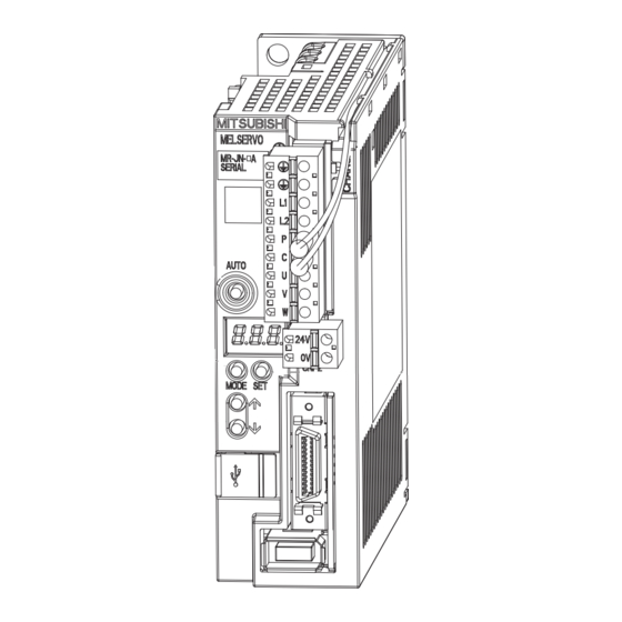
Page 42: Parts Identification
1. FUNCTIONS AND CONFIGURATION 1.7 Parts identification Detailed Name/Application explanation Serial number Main circuit power supply connector (CNP1) Section 3.1 Connect the input power supply/built-in regenerative Section 3.3 resistor/regenerative option/servo motor/earth. Charge lamp Lit to indicate that the main circuit is charged. While this lamp is lit, do not reconnect the cables. -
Page 43: Configuration Including Auxiliary Equipment
1. FUNCTIONS AND CONFIGURATION 1.8 Configuration including auxiliary equipment POINT Equipment other than the servo amplifier and servo motor are optional or recommended products. Servo amplifier (Note) Main circuit power supply Molded-case circuit breaker (MCCB) Regenerative option Magnetic AUTO contactor (MC) Power factor Circuit protector... -
Page 44: Installation
Do not install or operate a faulty servo amplifier. When the product has been stored for an extended period of time, consult Mitsubishi Electric. When handling the servo amplifier, be careful about the edged parts such as the corners of the servo amplifier. -
Page 45: Installation Direction And Clearances
2. INSTALLATION 2.1 Installation direction and clearances The equipment must be installed in the specified direction. Otherwise, a fault may occur. CAUTION Leave specified clearances between the servo amplifier and control box inside walls or other equipment. Doing so may cause malfunction to the equipment. A regenerative resistor is mounted on the back of this servo amplifier. -
Page 46: Keep Out Foreign Materials
2. INSTALLATION (2) Installation of two or more servo amplifiers POINT MR-JN series servo amplifier with any capacity can be mounted closely together. Leave a large clearance between the top of the servo amplifier and the internal surface of the control box, and install a cooling fan to prevent the internal temperature of the control box from exceeding the environmental conditions. -
Page 47: Cable Stress
2. INSTALLATION 2.3 Cable stress (1) The way of clamping the cable must be fully examined so that flexing stress and cable's own weight stress are not applied to the cable connection. (2) For use in any application where the servo motor moves, fix the cables (encoder, power supply, brake) with having some slack from the connector connection part of the servo motor to avoid putting stress on the connector connection part. -
Page 48: Parts Having Service Lives
2. INSTALLATION 2.5 Parts having service lives Service lives of the following parts are listed below. However, the service life varies depending on operating methods and environmental conditions. If any fault is found in the parts, they must be replaced immediately regardless of their service lives. - Page 49 2. INSTALLATION MEMO 2 - 6...
-
Page 50: Signals And Wiring
3. SIGNALS AND WIRING SIGNALS AND WIRING Any person who is involved in wiring should be fully competent to do the work. Before wiring, turn off the power and wait for 15 minutes or more until the charge lamp turns off. Otherwise, an electric shock may occur. In addition, always confirm from the front of the servo amplifier whether the charge lamp is off or not. -
Page 51: Input Power Supply Circuit
3. SIGNALS AND WIRING Connect the servo amplifier power output (U/V/W) to the servo motor power input (U/V/W) directly. Do not let a magnetic contactor, etc. intervene. Otherwise, it may cause a malfunction. Servo amplifier Servo motor Servo amplifier Servo motor CAUTION 3.1 Input power supply circuit Always connect a magnetic contactor (MC) between the main circuit power supply,... - Page 52 3. SIGNALS AND WIRING Wire the main circuit power supply as shown below so that the servo-on (SON) turns off as soon as alarm occurrence is detected and power is shut off. A molded-case circuit breaker (MCCB) must be used with the input cables of the main circuit power supply. Trouble Forced stop (Note 5) Servo amplifier...
-
Page 53: I/O Signal Connection Example
3. SIGNALS AND WIRING 3.2 I/O signal connection example 3.2.1 Position control mode 2m max. (Note 8) Programmable controller FX5U MT/ES (Note 13) Servo amplifier Programmable (Note 7) (Note 7) controller (Note 2) 24VDC power (Note 4, 10) DICOM supply Trouble (Note 6) (Note 10, 12) Electromagnetic... - Page 54 3. SIGNALS AND WIRING Note 1. To prevent an electric shock, always connect the protective earth (PE) terminal (terminal marked ) of the servo amplifier main circuit power connector (CNP1) to the protective earth (PE) of the control box. 2. Connect the diode in the correct direction. If it is connected reversely, the servo amplifier will be faulty and will not output signals, disabling the emergency stop and other protective circuits.
-
Page 55: Internal Speed Control Mode
3. SIGNALS AND WIRING 3.2.2 Internal speed control mode Servo amplifier (Note 7) (Note 7) (Note 4, 9) (Note 2) 24VDC DICOM Trouble (Note 6) DOCOM Speed reached (Note 3, 5) Forced stop (Note 9, 11) Servo-on Ready (Note 9, Reset 10, 12) Electromagnetic... -
Page 56: Internal Torque Control Mode
3. SIGNALS AND WIRING 3.2.3 Internal torque control mode Servo amplifier (Note 6) (Note 6) 24VDC (Note 4, 8) (Note 2) DICOM Trouble (Note 5) DOCOM Ready (Note 8, 10) (Note 3) Forced stop Servo-on Electromagnetic (Note 8, 9) brake interlock Reset Speed selection 1 Forward rotation selection... -
Page 57: Explanation Of Power Supply System
3. SIGNALS AND WIRING 3.3 Explanation of power supply system 3.3.1 Signal explanations POINT For the layout of connector, refer to chapter 9 DIMENSIONS. Connection target Abbreviation Description (application) Supply the following power supply. Main circuit power MR-JN-10A/20A/40A : 1-phase 200VAC to 230VAC, 50/60Hz supply MR-JN-10A1/20A1 : 1-phase 100VAC to 120VAC, 50/60Hz... - Page 58 3. SIGNALS AND WIRING (2) Timing chart Servo-on (SON) accepted (1 to 2s) Main circuit Control circuit Power supply Base circuit 10ms 10ms 95ms Servo-on (SON) 95ms Reset (RES) 10ms 10ms 10ms Ready (RD) No (ON) Trouble (ALM) Yes (OFF) Power-on timing chart (3) Forced stop Configure a circuit which interlocks with an external emergency stop switch in order...
-
Page 59: Cnp1 And Cnp2 Wiring Method
3. SIGNALS AND WIRING 3.3.3 CNP1 and CNP2 wiring method POINT Refer to section 11.5, for the wire sizes used for wiring. Use the supplied servo amplifier power supply connectors for wiring of CNP1 and CNP2. (1) Servo amplifier power supply connectors Servo amplifier CNP1 Connector for CNP1... - Page 60 3. SIGNALS AND WIRING (2) Termination of the wires (a) Solid wire The wire can be used just by stripping the sheath. Sheath Core Approx. 10mm (b) Twisted wire 1) Inserting the wires directly to the terminals Use the wire after stripping the sheath and twisting the core. At this time, take care to avoid a short caused by the loose wires of the core and the adjacent pole.
- Page 61 3. SIGNALS AND WIRING (3) Connection method (a) Inserting the wires directly to the terminals Insert the wire to the very end of the hole while pressing the button by a tool such as a small flat-blade screwdriver. Button Tools such as a small flat-blade screwdriver Twisted wire (b) Putting the wires together using a ferrule...
-
Page 62: Connectors And Signal Arrangements
3. SIGNALS AND WIRING 3.4 Connectors and signal arrangements POINT For the positioning mode, refer to section 13.2.2. The pin configurations of the connectors are as viewed from the cable connector wiring section. Refer to (2) in this section for CN1 signal assignment. (1) Signal arrangement The front view shown below is that of MR-JN-20A(1) or smaller. - Page 63 3. SIGNALS AND WIRING (2) CN1 signal assignment The signal assignment of connector changes with the control mode as indicated below; For the pins which are given parameter No. in the related parameter column, their signals can be changed using those parameters. (Note 1) (Note 2) I/O signals in control modes Related...
- Page 64 3. SIGNALS AND WIRING (3) Explanation of abbreviations Abbreviation Signal name Abbreviation Signal name Servo-on Trouble Reset In-position Proportion control Speed reached Forced stop Electromagnetic brake interlock Clear Limiting torque Forward rotation start Limiting speed Reverse rotation start Warning Forward rotation selection Zero speed Reverse rotation selection MTTR...
-
Page 65: Signal Explanations
3. SIGNALS AND WIRING 3.5 Signal explanations POINT For the positioning mode, refer to section 13.2.3. For the I/O interfaces (symbols in I/O division column in the table), refer to section 3.8.2. In the control mode field of the table P : Position control mode, S: Internal speed control mode, T: Internal torque control mode : Denotes that the signal may be used in the initial setting status. - Page 66 3. SIGNALS AND WIRING Control Connec- Device Symbol tor pin Functions/Applications mode division Internal The internal torque limit 2 (parameter No. PC14) becomes valid by turning DI-1 torque limit TL1 on. selection The forward torque limit (parameter No. PA11) and the reverse torque limit (parameter No.
- Page 67 3. SIGNALS AND WIRING Control Connec- Device Symbol tor pin Functions/Applications mode division <Internal speed control mode> Speed selection 1 DI-1 Used to select the command speed for operation. (Max. 8 speeds) (Note) Input device Speed command Internal speed command 0 (parameter No. PC05) Internal speed command 1 (parameter No.
- Page 68 3. SIGNALS AND WIRING Connec- Control mode Device Symbol tor pin Functions/Applications division Gain changing The values of the load to motor inertia moment ratio and the gains are DI-1 changed to the value set in parameter No. PB29 to PB34 by turning CDP Control change <Position/internal speed control change mode>...
- Page 69 3. SIGNALS AND WIRING Control Connec- Device Symbol tor pin Functions/Applications mode division Speed reached SA turns on when the servo motor speed has nearly reached the preset CN1-10 DO-1 speed. When the preset speed is 20r/min or less, SA always turns on. SA does not turn on even when the servo-on (SON) is turned off or the servo motor speed by the external force reaches the preset speed while both the forward rotation start (ST1) and the reverse rotation start (ST2)
- Page 70 3. SIGNALS AND WIRING (2) Input signals Control Connec- mode Signal Symbol Functions/Applications tor pin No. division Forward rotation CN1-23 Used to input command pulses. DI-2 (Note) pulse train CN1-25 In the open collector system (max. input frequency 200kpps) Reverse rotation CN1-22 Forward rotation pulse train across PP-DOCOM pulse train...
-
Page 71: Detailed Description Of The Signals
3. SIGNALS AND WIRING 3.6 Detailed description of the signals POINT For the positioning mode, refer to section 13.2.4. 3.6.1 Position control mode POINT The noise tolerance can be enhanced by setting parameter No. PA13 to "1 " when the command pulse frequency is 500kpps or less or "2 "... - Page 72 3. SIGNALS AND WIRING 2) Differential line driver type Connect as shown below. Servo amplifier Approx. (Note) Approx. Note. Pulse train input interface is comprised of a photo coupler. Therefore, it may be any malfunctions since the current is reduced when connect a resistance to a pulse train signal line.
- Page 73 3. SIGNALS AND WIRING (3) Ready (RD) Servo-on (SON) Alarm 10ms or less 100ms or less 10ms or less Ready (RD) (4) Torque limit If the torque limit is canceled during servo lock, the servo motor may suddenly rotate according to position deviation in respect to the command position. CAUTION When using the torque limit, check that load to motor inertia moment ratio (parameter No.
-
Page 74: Internal Speed Control Mode
3. SIGNALS AND WIRING (c) Limiting torque (TLC) TLC turns on when the servo motor torque reaches the torque limited by the forward torque limit, the reverse torque limit or the internal torque limit 2. 3.6.2 Internal speed control mode (1) Internal speed command settings (a) Speed command and speed The servo motor operates at the speed set in the parameters. - Page 75 3. SIGNALS AND WIRING POINT The servo-on (SON) can be set to turn on automatically by parameter No. PD01 (input signal automatic ON selection 1). The forward rotation stroke end (LSP) and the reverse rotation stroke end (LSN) switches as follows: Assigned to the external input signals: depends on the value set in parameter No.
- Page 76 3. SIGNALS AND WIRING (2) Speed reached (SA) SA turns on when the servo motor speed has nearly reached the speed set to the internal speed command. Internal speed Internal speed command 2 Set speed selection command 1 Forward rotation/ reverse rotation start (ST1/ST2) Servo motor speed...
-
Page 77: Internal Torque Control Mode
3. SIGNALS AND WIRING 3.6.3 Internal torque control mode (1) Internal torque command settings Torque is controlled by the internal torque command set in parameter No. PC12. If the internal torque command is small, the torque may vary when the actual speed reaches the speed limit value. - Page 78 3. SIGNALS AND WIRING (3) Speed limit (a) Speed limit value and speed The speed is limited to the values set in parameters No. PC05 to PC08 and PC31 to PC34 (Internal speed limit 0 to 7). When the servo motor speed reaches the speed limit value, the internal torque control may become unstable.
- Page 79 3. SIGNALS AND WIRING (b) Speed selection 1 (SP1) and speed limit values At the initial condition, the speed limit values for the internal speed limits 0 and 1 can be selected using the speed selection 1 (SP1). (Note) Input device Speed limit value Internal speed limit 0 (parameter No.
-
Page 80: Position/Speed Control Change Mode
3. SIGNALS AND WIRING 3.6.4 Position/speed control change mode Set parameter No. PA01 to " 1 " to switch to the position/internal speed control change mode. (1) Control change (LOP) By using the control change (LOP), control mode can be switched between the position control and the internal speed control modes from an external contact. -
Page 81: Internal Speed/Internal Torque Control Change Mode
3. SIGNALS AND WIRING 3.6.5 Internal speed/internal torque control change mode Set No. PA01 to " 3 " to switch to the internal speed/internal torque control change mode. (1) Control change (LOP) By using the control change (LOP), the control mode can be switched between the internal speed control and the internal torque control mode from an external contact. -
Page 82: Internal Torque/Position Control Change Mode
3. SIGNALS AND WIRING 3.6.6 Internal torque/position control change mode Set parameter No. PA01 to " 5 " to switch to the internal torque/position control change mode. (1) Control change (LOP) By using the control change (LOP), the control mode can be switched between the internal torque control and the position control modes from an external contact. -
Page 83: Alarm Occurrence Timing Chart
3. SIGNALS AND WIRING 3.7 Alarm occurrence timing chart When an alarm has occurred, remove its cause, make sure that the operation signal is not being input, ensure safety, and reset the alarm before restarting CAUTION operation. As soon as an alarm occurs, turn off servo-on (SON) and power off. When an alarm occurs in the servo amplifier, the base circuit is shut off and the servo motor is coated to a stop. -
Page 84: Interfaces
3. SIGNALS AND WIRING 3.8 Interfaces 3.8.1 Internal connection diagram Servo amplifier (Note 1) (Note 1) CP/CL CP/CL Approx. 5.6k SON SON SON ALM ALM RES RES RES EM1 EM1 EM1 (Note (Note LSP ST1 LSN ST2 MBR MBR Approx. 5.6k 24VDC DICOM <Isolated>... -
Page 85: Detailed Description Of Interfaces
3. SIGNALS AND WIRING 3.8.2 Detailed description of interfaces This section provides the details of the I/O signal interfaces (refer to the I/O division in the table) given in section 3.5. Refer to this section and make connection with the external equipment. (1) Digital input interface DI-1 Give a signal with a relay or open collector transistor. - Page 86 3. SIGNALS AND WIRING (3) Pulse train input interface DI-2 Give a pulse train signal in the open collector system or differential line driver type. (a) Open collector system 1) Interface Servo amplifier Max. input pulse 24VDC frequency 200kpps Approx. 1.2k 2m or less (Note) PP, NP...
- Page 87 3. SIGNALS AND WIRING 2) Input pulse condition tLH=tHL<0.1 s tc>0.35 s PP PG tF>3 s NP NG (4) Encoder output pulse DO-2 (a) Open collector system Interface Max. output current: 35mA 5 to 24VDC Servo amplifier Servo amplifier Photocoupler (b) Differential line driver type 1) Interface Max.
-
Page 88: Source I/O Interfaces
3. SIGNALS AND WIRING 2) Output pulse Servo motor CCW rotation Time cycle (T) is determined by the settings of parameter No.PA15 and PC13. 400 s or more 3.8.3 Source I/O interfaces In this servo amplifier, source type I/O interfaces can be used. In this case, all DI-1 input signals and DO-1 output signals are of source type. -
Page 89: Treatment Of Cable Shield External Conductor
3. SIGNALS AND WIRING 3.9 Treatment of cable shield external conductor In the case of the CN1 and CN2 connectors, securely connect the shielded external conductor of the cable to the ground plate as shown in this section and fix it to the connector shell. External conductor Sheath Core... -
Page 90: Connection Of Servo Amplifier And Servo Motor
3. SIGNALS AND WIRING 3.10 Connection of servo amplifier and servo motor Connect the servo amplifier power output (U/V/W) to the servo motor power input CAUTION (U/V/W) directly. Do not connect a magnetic contactor and others between them. Otherwise, it may cause a malfunction. 3.10.1 Connection instructions WARNING To avoid an electric shock, insulate the connections of the power supply terminals. -
Page 91: Power Supply Cable Wiring Diagrams
3. SIGNALS AND WIRING 3.10.2 Power supply cable wiring diagrams (1) HF-KN series HF-KP G1/G5/G7 HG-KR G1/G5/G7 servo motor (a) When cable length is 10m or less 10m or less MR-PWS1CBL M-A1-L MR-PWS1CBL M-A2-L MR-PWS1CBL M-A1-H Servo amplifier Servo motor MR-PWS1CBL M-A2-H CNP1 AWG 19(red) -
Page 92: Specifications ꞏꞏꞏꞏꞏꞏꞏꞏꞏꞏꞏꞏꞏꞏꞏꞏꞏꞏꞏꞏꞏꞏꞏꞏꞏꞏꞏꞏꞏꞏꞏꞏꞏꞏꞏꞏꞏꞏꞏꞏꞏꞏꞏꞏꞏꞏꞏꞏꞏꞏꞏꞏꞏꞏꞏꞏꞏꞏꞏꞏꞏꞏꞏꞏꞏꞏꞏꞏꞏꞏꞏꞏꞏꞏꞏꞏꞏꞏꞏꞏꞏꞏꞏꞏꞏꞏꞏꞏꞏꞏꞏꞏꞏꞏꞏꞏꞏꞏꞏꞏꞏꞏꞏꞏ
3. SIGNALS AND WIRING 3.11 Servo motor with an electromagnetic brake 3.11.1 Safety precautions Configure an electromagnetic brake operation circuit which interlocks with an external emergency stop switch. Shut off the servo motor when Circuit must be opened Servo-on (SON), Malfunction with the emergency stop (ALM), or Electromagnetic brake switch. -
Page 93: Timing Chartsꞏꞏꞏꞏꞏꞏꞏꞏꞏꞏꞏꞏꞏꞏꞏꞏꞏꞏꞏꞏꞏꞏꞏꞏꞏꞏꞏꞏꞏꞏꞏꞏꞏꞏꞏꞏꞏꞏꞏꞏꞏꞏꞏꞏꞏꞏꞏꞏꞏꞏꞏꞏꞏꞏꞏꞏꞏꞏꞏꞏꞏꞏꞏꞏꞏꞏꞏꞏꞏꞏꞏꞏꞏꞏꞏꞏꞏꞏꞏꞏꞏꞏꞏꞏꞏꞏꞏꞏꞏꞏꞏꞏꞏꞏꞏꞏꞏꞏꞏꞏꞏꞏꞏꞏꞏꞏ
3. SIGNALS AND WIRING 3.11.3 Timing charts (1) Servo-on (SON) command (from controller) ON/OFF Tb [ms] after the servo-on (SON) signal is switched off, the servo lock is released and the servo motor coasts. If the electromagnetic brake is made valid in the servo lock status, the brake life may be shorter. Therefore, when using the electromagnetic brake in a vertical lift application or the like, set Tb to about the same as the electromagnetic brake operation delay time to prevent a drop. - Page 94 3. SIGNALS AND WIRING (3) Alarm occurrence Dynamic brake Dynamic brake Electromagnetic brake Servo motor speed Electromagnetic brake (10ms) Base circuit (Note 1) Electromagnetic brake operation delay time (Note 2) ON Electromagnetic brake interlock (MBR) No (ON) Trouble (ALM) Yes (OFF) Note 1.
-
Page 95: Wiring Diagrams (Hf-Kn Series • Hf-Kp G1/G5/G7 • Hg-Kr G1/G5/G7 Servo Motor) ꞏꞏꞏꞏꞏ
3. SIGNALS AND WIRING (5) Only main circuit power supply off (control circuit power supply remains on) Deceleration starts after the trouble (ALM) turns OFF. (Note 2) Dynamic brake Dynamic brake (10ms) Electromagnetic brake Servo motor speed Electromagnetic brake Electromagnetic brake sequence output Base circuit (parameter No. - Page 96 3. SIGNALS AND WIRING (2) When cable length exceeds 10m When the cable length exceeds 10m, fabricate an extension cable as shown below on the customer side. In this case, the motor brake cable should be within 2m long. Refer to section 11.5 for the wire used for the extension cable. 2m or less MR-BKS1CBL2M-A1-L 50m or less...
-
Page 97: Grounding ꞏꞏꞏꞏꞏꞏꞏꞏꞏꞏꞏꞏꞏꞏꞏꞏꞏꞏꞏꞏꞏꞏꞏꞏꞏꞏꞏꞏꞏꞏꞏꞏꞏꞏꞏꞏꞏꞏꞏꞏꞏꞏꞏꞏꞏꞏꞏꞏꞏꞏꞏꞏꞏꞏꞏꞏꞏꞏꞏꞏꞏꞏꞏꞏꞏꞏꞏꞏꞏꞏꞏꞏꞏꞏꞏꞏꞏꞏꞏꞏꞏꞏꞏꞏꞏꞏꞏꞏꞏꞏꞏꞏꞏꞏꞏꞏꞏꞏꞏꞏꞏꞏꞏꞏꞏꞏꞏꞏꞏꞏꞏꞏꞏꞏꞏ
3. SIGNALS AND WIRING 3.12 Grounding Ground the servo amplifier and servo motor securely. To prevent an electric shock, always connect the protective earth (PE) terminal WARNING (terminal marked ) of the servo amplifier with the protective earth (PE) of the control box. - Page 98 4. PARAMETERS 4. PARAMETERS Never make a drastic adjustment or change to the parameter values, as doing so will make the operation unstable. Do not change the parameter settings as described below. Doing so may cause an unexpected condition, such as failing to start up the servo amplifier. CAUTION Changing the values of the parameters for manufacturer setting.
- Page 99 4. PARAMETERS 4.1 Basic setting parameters (No. PA POINT For any parameter whose symbol is preceded by *, set the parameter value and switch power off once, then switch it on again to make that parameter setting valid. Never change parameters for manufacturer setting. 4.1.1 Parameter list Control mode Initial...
- Page 100 4. PARAMETERS 4.1.2 Parameter write inhibit Parameter Control mode Initial Setting Unit Internal Internal value range Symbol Name Position speed torque Refer to PA19 *BLK Parameter write inhibit 00Eh the text. POINT This parameter is made valid when power is switched off, then on after setting. In the factory setting, this servo amplifier allows to change all the setting parameters.
- Page 101 4. PARAMETERS 4.1.3 Selection of control mode Parameter Control mode Initial Setting Unit Internal Internal value range Symbol Name Position speed torque Refer to PA01 *STY Control mode 000h the text. POINT This parameter is made valid when power is switched off, then on after setting. Select the control mode of the servo amplifier, and valid or invalid the one-touch tuning function.
- Page 102 4. PARAMETERS 4.1.5 Selection of the tough drive function Parameter Control mode Initial Setting Unit Internal Internal value range Symbol Name Position speed torque Refer to PA04 *AOP1 Tough drive function selection 000h the text. POINT This parameter is made valid when power is switched off, then on after setting. The alarm may not be avoided in the tough drive depending on the conditions of the power supply and the load change.
- Page 103 4. PARAMETERS 4.1.6 Number of command input pulses per servo motor revolution Parameter Control mode Initial Setting Unit Internal Internal value range Symbol Name Position speed torque 0 100 PA05 *FBP Number of command input pulses per revolution to 500 pulses/rev POINT This parameter is made valid when power is switched off, then on after setting.
- Page 104 4. PARAMETERS 4.1.7 Electronic gear Parameter Control mode Initial Setting Unit Internal Internal value range Symbol Name Position speed torque Electronic gear numerator 1 to PA06 (Command pulse multiplying factor numerator) 65535 Electronic gear denominator 1 to PA07 (Command pulse multiplying factor denominator) 65535 CAUTION Incorrect setting may cause unexpectedly fast rotation, resulting injury.
- Page 105 4. PARAMETERS (a) For motion in increments of 10μm per pulse Machine specifications 1/n=Z =1/2 Ballscrew lead Pb 10 [mm] Reduction ratio: 1/n = Z = 1/2 Pb=10[mm] : Number of gear cogs on servo motor side Number of command input pulses : Number of gear cogs on load side per revolution of servo motor: Command input pulses per revolution: 10000...
- Page 106 4. PARAMETERS (2) Setting for use of QD75 The QD75 also has the following electronic gear parameters. Normally, the servo amplifier side electronic gear must also be set due to the restriction on the command pulse frequency (differential 1Mpulse/s, open collector 200kpulse/s).
- Page 107 4. PARAMETERS The following table indicates the electronic gear setting example (ballscrew lead = 10mm) when the QD75 is used in this way. Rated servo motor speed 3000r/min 2000r/min Open Differential Open Differential Input system collector line driver collector line driver Max.
- Page 108 4. PARAMETERS 4.1.8 Auto tuning Parameter Control mode Initial Setting Unit Internal Internal value range Symbol Name Position speed torque Refer to PA08 Auto tuning mode 001h the text. PA09 Auto tuning response 1 to 16 POINT When executing one-touch tuning, the setting value of parameter No. PA08 is changed to "...
- Page 109 4. PARAMETERS (2) Auto tuning response (parameter No. PA09) If the machine hunts or generates large gear sound, decrease the set value. To improve performance, e.g. shorten the settling time, increase the set value. Setting Response Low response High response 4.1.9 In-position range Parameter Control mode...
- Page 110 4. PARAMETERS 4.1.10 Torque limit Parameter Control mode Initial Setting Unit Internal Internal value range Symbol Name Position speed torque PA11 Forward torque limit 0 to 100 PA12 Reverse torque limit 0 to 100 The torque generated by the servo motor can be limited. Refer to section 3.6.1 (4) and use these parameters. (1) Forward torque limit (parameter No.
- Page 111 4. PARAMETERS 4.1.11 Selection of command input pulse form Parameter Control mode Initial Setting Unit Internal Internal value range Symbol Name Position speed torque Refer to PA13 *PLSS Command input pulse form 000h the text. POINT This parameter is made valid when power is switched off, then on after setting. The noise tolerance can be enhanced by setting parameter No.
- Page 112 4. PARAMETERS 4.1.12 Selection of servo motor rotation direction Parameter Control mode Initial Setting Unit Internal Internal value range Symbol Name Position torque speed PA14 *POL Rotation direction selection POINT This parameter is made valid when power is switched off, then on after setting. Select servo motor rotation direction relative to the input pulse train.
- Page 113 4. PARAMETERS 4.1.13 Encoder output pulses Parameter Control mode Initial Setting Unit Internal Internal value range Symbol Name Position speed torque 1 to pulse/ PA15 *ENR Encoder output pulses 4000 65535 0 to PA16 *ENR2 Encoder output pulse electronic gear 65535 POINT This parameter is made valid when power is switched off, then on after setting.
- Page 114 4. PARAMETERS (2) For output division ratio setting Set parameter No. PC13 to " ". The number of pulses per servo motor revolution is divided by the set value. Resolution per servo motor revolution Output pulse= [pulse/rev] Setting valve For instance, when parameter No. PA15 is set to "8", the A/B-phase pulses actually output are as indicated below.
- Page 115 4. PARAMETERS (4) When multiplying A-phase/B-phase output pulses by the value of the electronic gear Set parameter No. PC13 to " 3 ". The value resulted from multiplying the number of pulses per servo motor revolution by the value of the electronic gear becomes the output pulse.
- Page 116 4. PARAMETERS 4.2 Gain/filter parameters (No. PB POINT For any parameter whose symbol is preceded by *, set the parameter value and switch power off once, then switch it on again to make that parameter setting valid. Set any parameter with [Applied] written in the name column when using an advanced function.
- Page 117 4. PARAMETERS Control mode Initial No. Symbol Name Unit Internal Internal value Position speed torque Gain changing vibration suppression control resonance frequency PB34 VRF2B [Applied] 100.0 setting PB35 For manufacturer setting PB36 PB37 PB38 NH3 4500 Machine resonance suppression filter 3 PB39 NHQ3 Notch shape selection 3 000h PB40...
- Page 118 4. PARAMETERS 4.2.2 Detail list Control mode Initial Setting No. Symbol Name and function Unit Internal Internal value range Position speed torque PB01 FILT Adaptive tuning mode (Adaptive filter II) 000h Refer to name POINT function When executing one-touch tuning, the adaptive column.
- Page 119 4. PARAMETERS Control mode Initial Setting No. Symbol Name and function Unit Internal Internal value range Position speed torque PB02 VRFT Vibration suppression control tuning mode (Advanced vibration 000h Refer to suppression control) name POINT function When using the vibration suppression control column.
- Page 120 4. PARAMETERS Control mode Initial Setting No. Symbol Name and function Unit Internal Internal value range Position speed torque PB03 PST Position command acceleration/deceleration time constant (Position smoothing) Used to set the time constant of a low-pass filter in response to the 20000 position command.
- Page 121 4. PARAMETERS Control mode Initial Setting No. Symbol Name and function Unit Internal Internal value range Position speed torque PB06 GD2 Load to motor inertia moment ratio Multiplier Used to set the load to motor inertia moment ratio. Setting a value that is considerably different from the actual load 300.0 moment of inertia may cause an unexpected operation such as an overshoot.
- Page 122 4. PARAMETERS Control mode Initial Setting No. Symbol Name and function Unit Internal Internal value range Position speed torque PB13 NH1 Machine resonance suppression filter 1 4500 Set the notch frequency of the machine resonance suppression filter 1. Executing one-touch tuning automatically changes this parameter. 4500 When parameter No.
- Page 123 4. PARAMETERS Control mode Initial Setting No. Symbol Name and function Unit Internal Internal value range Position speed torque PB17 Automatic setting parameter The value of this parameter is set according to a set value of parameter No. PB06 (load to motor inertia moment ratio). PB18 LPF Low-pass filter setting [Applied] 3141...
- Page 124 4. PARAMETERS Control mode Initial Setting No. Symbol Name and function Unit Internal Internal value range Position speed torque PB26 *CDP Gain changing [Applied] 000h Refer to Select the gain changing condition. (Refer to section 7.3.) name function column. Gain changing selection Under any of the following conditions, the gains change on the basis of parameter No.
- Page 125 4. PARAMETERS Control mode Initial Setting No. Symbol Name and function Unit Internal Internal value range Position speed torque PB34 VRF2B Gain changing vibration suppression control resonance frequency 100.0 setting [Applied] Set the resonance frequency for vibration suppression control when 100.0 the gain changing is valid.
- Page 126 4. PARAMETERS 4.2.3 Position smoothing By setting the position command acceleration/deceleration time constant (parameter No. PB03), the servo motor is operated smoothly in response to a sudden position command. The following diagrams show the operation patterns of the servo motor in response to a position command when the position command acceleration/deceleration time constant is set.
- Page 127 4. PARAMETERS 4.3 Extension setting parameters (No. PC POINT For any parameter whose symbol is preceded by *, set the parameter value and switch power off once, then switch it on again to make that parameter setting valid. Set any parameter with [Applied] written in the name column when using an advanced function.
- Page 128 4. PARAMETERS Control mode Initial Symbol Name Unit Internal Internal value Position speed torque Internal speed command 6 PC33 [Applied] 500 r/min Internal speed limit 6 [Applied] Internal speed command 7 PC34 [Applied] 800 r/min Internal speed limit 7 [Applied] PC35 For manufacturer setting 000h...
- Page 129 4. PARAMETERS 4.3.2 List of details Control mode Initial Setting No. Symbol Name and function Unit Internal Internal value range Position speed torque PC01 STA Acceleration time constant Used to set the acceleration time required for the servo motor to reach the rated speed from 0r/min in response to the internal speed 50000 commands 0 to 7.
- Page 130 4. PARAMETERS Control mode Initial Setting No. Symbol Name and function Unit Internal Internal value range Position speed torque PC03 STC S-pattern acceleration/deceleration time constant Used to smooth start/stop of the servo motor. Set the time of the arc part for S-pattern acceleration/deceleration. 1000 Set "0"...
- Page 131 4. PARAMETERS Control mode Initial Setting No. Symbol Name and function Unit Internal Internal value range Position speed torque PC05 SC0 Internal speed command 0 0 to r/min Used to set speed 0 of internal speed commands. instan- taneous permi- Internal speed limit 0 ssible Used to set speed 0 of internal speed limits.
- Page 132 4. PARAMETERS Control mode Initial Setting No. Symbol Name and function Unit Internal Internal value range Position speed torque PC12 Internal torque command Set the internal torque command during the internal torque control. Set the parameter on the assumption that the maximum torque is 100.0 100.0 %.
- Page 133 4. PARAMETERS Control mode Initial Setting No. Symbol Name and function Unit Internal Internal value range Position speed torque PC22 *COP1 Function selection C-1 [Applied] 000h Refer to the name Select the encoder cable communication system. function field. Encoder cable communication system 0: Two-wire type 1: Four-wire type Incorrect setting will result in an encoder transmission...
- Page 134 4. PARAMETERS Control mode Initial Setting No. Symbol Name and function Unit Internal Internal value range Position speed torque PC26 ALDT Detailed setting of overload tough drive [Applied] Limits the maximum value of the output time delay of the in-position (INP) and zero speed (ZSP) while the overload tough drive.
- Page 135 4. PARAMETERS Control mode Initial Setting No. Symbol Name and function Unit Internal Internal value range Position speed torque PC32 SC5 Internal speed command 5 [Applied] 0 to r/min Used to set speed 5 of internal speed commands. instan- taneous permi- Internal speed limit 5 [Applied] Used to set speed 5 of internal speed limits.
- Page 136 4. PARAMETERS Control mode Initial Setting No. Symbol Name and function Unit Internal Internal value range Position speed torque PC57 000h PC58 *COP9 Function selection C-9 000h Refer to When using the electronic dynamic brake, set this parameter. This parameter setting is available with servo amplifiers with software "Name version B2 or later.
- Page 137 4. PARAMETERS 4.3.4 Drive recorder function POINT Records the state transition when an alarm occurs. However, the previously recorded data is discarded. If another alarm occurs while an alarm is occurring, the state transition during that another alarm is not recorded. The drive recorder does not operate in the following situation.
- Page 138 4. PARAMETERS Specify the alarm No. in parameter No. PC44 when operating the drive recorder with the specific alarm No. Parameter No. PC44 Specification of alarm No. : No specification (The optimum item is recorded according to the alarms that have occurred earlier and operating conditions.) 01 to FFh : Specification (The specified item is recorded when an alarm of the specified alarm No.
- Page 139 4. PARAMETERS (b) When the set value of parameter No. PC44 is other than " 00": The data to be recorded are as indicated in the following table. Digital CH data Sampling Measuring Corresponding Setting Analog CH data time length [ms] alarm No.
- Page 140 4. PARAMETERS Digital CH data Sampling Measuring Corresponding Setting Analog CH data time length [ms] alarm No. [ms] (64 points) (trigger) CH1 Servo motor speed [r/min] CH2 Torque [%] CH3 Droop pulses [pulse] (unit: 100 pulses) CH1 Servo motor speed [r/min] CH2 Torque [%] 56.8 CH3 Within one-revolution position [pulse]...
- Page 141 4. PARAMETERS 4.4 I/O setting parameters (No. PD POINT For any parameter whose symbol is preceded by *, set the parameter value and switch power off once, then switch it on again to make that parameter setting valid. In the positioning mode, refer to section 13.7.4 (2) for the parameter No. PD20. 4.4.1 Parameter list Control mode No.
- Page 142 4. PARAMETERS 4.4.2 List of details Control mode Initial Setting No. Symbol Name and function Unit Internal Internal value range Position speed torque PD01 *DIA1 Input signal automatic ON selection 1 0000h Refer to Select the input devices to be automatically turned ON. the name function field.
- Page 143 4. PARAMETERS Control mode Initial Setting No. Symbol Name and function Unit Internal Internal value range Position speed torque Input signal device selection 0 (CN1-23, CN1-25) PD02 *DI0 262Dh Refer to Any input device can be assigned to the CN1-23 pin and CN1-25 the name pin (forward and reverse rotation pulse trains).
- Page 144 4. PARAMETERS Control mode Initial Setting No. Symbol Name and function Unit Internal Internal value range Position speed torque PD03 *DI1-1 Input signal device selection 1L (CN1-3) 0303h Refer to Any input signal can be assigned to the CN1-3 pin. the name Note that the setting digits and the signal that can be assigned vary depending on the control mode.
- Page 145 4. PARAMETERS Control mode Initial Setting No. Symbol Name and function Unit Internal Internal value range Position speed torque PD04 *DI1-2 Input signal device selection 1H (CN1-3) 2003h Refer to Any input signal can be assigned to the CN1-3 pin. the name The devices that can be assigned and the setting method are the same as in parameter No.
- Page 146 4. PARAMETERS Control mode Initial Setting No. Symbol Name and function Unit Internal Internal value range Position speed torque PD09 *DI4-1 Input signal device selection 4L (CN1-6) 070Ah Refer to Any input signal can be assigned to the CN1-6 pin. the name The devices that can be assigned and the setting method are the same as in parameter No.
- Page 147 4. PARAMETERS Control mode Initial Setting No. Symbol Name and function Unit Internal Internal value range Position speed torque PD14 *DI6-2 Input signal device selection 6H (CN1-8) 0505h Refer to Any input signal can be assigned to the CN1-8 pin. the name The devices that can be assigned and the setting method are the same as in parameter No.
- Page 148 4. PARAMETERS Control mode Initial Setting No. Symbol Name and function Unit Internal Internal value range Position speed torque PD15 *DO1 Output signal device selection 1 (CN1-9) 0003h Refer to Any output signal can be assigned to the CN1-9pin. ALM is the name assigned as the initial value.
- Page 149 4. PARAMETERS Control mode Initial Setting No. Symbol Name and function Unit Internal Internal value range Position speed torque PD16 *DO2 Output signal device selection 2 (CN1-10) 0004h Refer to Any output signal can be assigned to the CN1-10 pin. INP is the name assigned as the initial value.
- Page 150 4. PARAMETERS Control mode Initial Setting No. Symbol Name and function Unit Internal Internal value range Position speed torque PD20 *DOP1 Function selection D-1 0000h Refer to Select the stop processing at forward rotation stroke end the name (LSP)/reverse rotation stroke end (LSN) OFF, the base circuit status at reset (RES) ON and the operation during tough drive (MTTR).
- Page 151 4. PARAMETERS Control mode Initial Setting No. Symbol Name and function Unit Internal Internal value range Position speed torque PD25 For manufacturer setting 0000h PD26 Do not change this value by any means. 0000h 4.4.3 Using forward/reverse rotation stroke end to change the stopping pattern In the initial value, the servo motor makes a sudden stop when the forward/reverse rotation stroke end turns OFF.
-
Page 152: Overview ꞏꞏꞏꞏꞏꞏꞏꞏꞏꞏꞏꞏꞏꞏꞏꞏꞏꞏꞏꞏꞏꞏꞏꞏꞏꞏꞏꞏꞏꞏꞏꞏꞏꞏꞏꞏꞏꞏꞏꞏꞏꞏꞏꞏꞏꞏꞏꞏꞏꞏꞏꞏꞏꞏꞏꞏꞏꞏꞏꞏꞏꞏꞏꞏꞏꞏꞏꞏꞏꞏꞏꞏꞏꞏꞏꞏꞏꞏꞏꞏꞏꞏꞏꞏꞏꞏꞏꞏꞏꞏꞏꞏꞏꞏꞏꞏꞏꞏꞏꞏꞏꞏꞏꞏꞏꞏꞏꞏꞏꞏꞏꞏꞏꞏꞏꞏꞏꞏꞏ
5. DISPLAY AND OPERATION 5. DISPLAY AND OPERATION SECTIONS POINT Positioning mode is supported by servo amplifier with software version B0 or later. 5.1 Overview MR-JN-A servo amplifier has a display section (3-digit, 7-segment LED), operation section (4 pushbuttons) and a one-touch tuning button for servo amplifier status display, alarm display, parameter and point table setting, etc. -
Page 153: Display Sequence ꞏꞏꞏꞏꞏꞏꞏꞏꞏꞏꞏꞏꞏꞏꞏꞏꞏꞏꞏꞏꞏꞏꞏꞏꞏꞏꞏꞏꞏꞏꞏꞏꞏꞏꞏꞏꞏꞏꞏꞏꞏꞏꞏꞏꞏꞏꞏꞏꞏꞏꞏꞏꞏꞏꞏꞏꞏꞏꞏꞏꞏꞏꞏꞏꞏꞏꞏꞏꞏꞏꞏꞏꞏꞏꞏꞏꞏꞏꞏꞏꞏꞏꞏꞏꞏꞏꞏꞏꞏꞏꞏꞏꞏꞏꞏꞏꞏꞏꞏꞏꞏꞏꞏꞏꞏꞏꞏꞏ
5. DISPLAY AND OPERATION SECTIONS 5.2 Display sequence Press the "MODE" button once to shift to the next display mode. Refer to section 5.3 and later for the description of the corresponding display mode. To refer to or set the gain/filter parameters, extension setting parameters, I/O setting parameters and positioning setting parameters, make them valid with parameter No. -
Page 154: Status Display ꞏꞏꞏꞏꞏꞏꞏꞏꞏꞏꞏꞏꞏꞏꞏꞏꞏꞏꞏꞏꞏꞏꞏꞏꞏꞏꞏꞏꞏꞏꞏꞏꞏꞏꞏꞏꞏꞏꞏꞏꞏꞏꞏꞏꞏꞏꞏꞏꞏꞏꞏꞏꞏꞏꞏꞏꞏꞏꞏꞏꞏꞏꞏꞏꞏꞏꞏꞏꞏꞏꞏꞏꞏꞏꞏꞏꞏꞏꞏꞏꞏꞏꞏꞏꞏꞏꞏꞏꞏꞏꞏꞏꞏꞏꞏꞏꞏꞏꞏꞏꞏꞏꞏꞏꞏꞏꞏꞏꞏꞏꞏꞏꞏ
5. DISPLAY AND OPERATION SECTIONS 5.3 Status display The servo status during operation is shown on the 3-digit, 7-segment LED display. Press the "UP" or the "DOWN" button to change the display data as desired. When the required data is selected, the corresponding symbol appears. -
Page 155: Display Transition ꞏꞏꞏꞏꞏꞏꞏꞏꞏꞏꞏꞏꞏꞏꞏꞏꞏꞏꞏꞏꞏꞏꞏꞏꞏꞏꞏꞏꞏꞏꞏꞏꞏꞏꞏꞏꞏꞏꞏꞏꞏꞏꞏꞏꞏꞏꞏꞏꞏꞏꞏꞏꞏꞏꞏꞏꞏꞏꞏꞏꞏꞏꞏꞏꞏꞏꞏꞏꞏꞏꞏꞏꞏꞏꞏꞏꞏꞏꞏꞏꞏꞏꞏꞏꞏꞏꞏꞏꞏꞏꞏꞏꞏꞏꞏꞏꞏꞏꞏꞏꞏꞏꞏ
5. DISPLAY AND OPERATION SECTIONS 5.3.1 Display transition After selecting the status display mode by the "MODE" button, pressing the "UP" or the "DOWN" button changes the display as shown below. To Step No. Cumulative feedback pulses in pulse Within one-revolution position unit in pulse unit Within one-revolution position... -
Page 156: Display Examples ꞏꞏꞏꞏꞏꞏꞏꞏꞏꞏꞏꞏꞏꞏꞏꞏꞏꞏꞏꞏꞏꞏꞏꞏꞏꞏꞏꞏꞏꞏꞏꞏꞏꞏꞏꞏꞏꞏꞏꞏꞏꞏꞏꞏꞏꞏꞏꞏꞏꞏꞏꞏꞏꞏꞏꞏꞏꞏꞏꞏꞏꞏꞏꞏꞏꞏꞏꞏꞏꞏꞏꞏꞏꞏꞏꞏꞏꞏꞏꞏꞏꞏꞏꞏꞏꞏꞏꞏꞏꞏꞏꞏꞏꞏꞏꞏꞏꞏꞏꞏꞏꞏꞏ
5. DISPLAY AND OPERATION SECTIONS 5.3.2 Display examples POINT The following is priority order of the status display when two or more decimal points need to be displayed. 1. Alarm occurrence, test operation 2. Negative values The following table lists display examples. Displayed data Item Status... - Page 157 5. DISPLAY AND OPERATION SECTIONS Displayed data Item Status Servo amplifier display Pulse unit 720000pulses 1000 pulse unit Cumulative feedback pulses Pulse unit Negative value is indicated by the lit decimal points in the upper two digits. -680000pulses 1000 pulse unit Negative value is indicated by the lit decimal points in the upper two digits.
-
Page 158: Status Display List ꞏꞏꞏꞏꞏꞏꞏꞏꞏꞏꞏꞏꞏꞏꞏꞏꞏꞏꞏꞏꞏꞏꞏꞏꞏꞏꞏꞏꞏꞏꞏꞏꞏꞏꞏꞏꞏꞏꞏꞏꞏꞏꞏꞏꞏꞏꞏꞏꞏꞏꞏꞏꞏꞏꞏꞏꞏꞏꞏꞏꞏꞏꞏꞏꞏꞏꞏꞏꞏꞏꞏꞏꞏꞏꞏꞏꞏꞏꞏꞏꞏꞏꞏꞏꞏꞏꞏꞏꞏꞏꞏꞏꞏꞏꞏꞏꞏꞏꞏꞏꞏꞏꞏ
5. DISPLAY AND OPERATION SECTIONS 5.3.3 Status display list POINT Refer to appendix 4 for the measurement point. The following table lists the servo statuses that may be shown. Display Name Symbol Unit Description range Feedback pulses from the servo motor encoder are counted and Cumulative feedback pulse -999 to 999... - Page 159 5. DISPLAY AND OPERATION SECTIONS Display Name Symbol Unit Description range Current position in m The current position is displayed based on the machine home position -999 to 999 m unit (Note 1) being regarded as "0". Negative values are indicated by the lit decimal points in the upper two Current position in 1000 1000 -999 to 999...
-
Page 160: Diagnostic Mode ꞏꞏꞏꞏꞏꞏꞏꞏꞏꞏꞏꞏꞏꞏꞏꞏꞏꞏꞏꞏꞏꞏꞏꞏꞏꞏꞏꞏꞏꞏꞏꞏꞏꞏꞏꞏꞏꞏꞏꞏꞏꞏꞏꞏꞏꞏꞏꞏꞏꞏꞏꞏꞏꞏꞏꞏꞏꞏꞏꞏꞏꞏꞏꞏꞏꞏꞏꞏꞏꞏꞏꞏꞏꞏꞏꞏꞏꞏꞏꞏꞏꞏꞏꞏꞏꞏꞏꞏꞏꞏꞏꞏꞏꞏꞏꞏꞏꞏꞏꞏꞏꞏꞏꞏꞏꞏꞏꞏꞏ
5. DISPLAY AND OPERATION SECTIONS 5.4 Diagnostic mode Name Display Description Not ready. Indicates that the servo amplifier is being initialized or an alarm has occurred. Sequence Ready. Indicates that the servo was switched on after completion of initialization and the servo amplifier is ready to operate. - Page 161 5. DISPLAY AND OPERATION SECTIONS Name Display Description Indicates the lower two digits of the system number of the software. Three digits are displayed by pressing Software version high the "SET" button. Series ID of the servo motor currently connected will be displayed by pressing the "SET"...
-
Page 162: Alarm Mode ꞏꞏꞏꞏꞏꞏꞏꞏꞏꞏꞏꞏꞏꞏꞏꞏꞏꞏꞏꞏꞏꞏꞏꞏꞏꞏꞏꞏꞏꞏꞏꞏꞏꞏꞏꞏꞏꞏꞏꞏꞏꞏꞏꞏꞏꞏꞏꞏꞏꞏꞏꞏꞏꞏꞏꞏꞏꞏꞏꞏꞏꞏꞏꞏꞏꞏꞏꞏꞏꞏꞏꞏꞏꞏꞏꞏꞏꞏꞏꞏꞏꞏꞏꞏꞏꞏꞏꞏꞏꞏꞏꞏꞏꞏꞏꞏꞏꞏꞏꞏꞏꞏꞏꞏꞏꞏꞏꞏꞏꞏꞏꞏꞏꞏꞏ
5. DISPLAY AND OPERATION SECTIONS 5.5 Alarm mode The current alarm, the past alarm history, the number of tough drive, the number of drive recorder record times, and the parameter error No. are displayed. The lower 2 digits on the display indicate the alarm number that has occurred or the parameter number in error. - Page 163 5. DISPLAY AND OPERATION SECTIONS Name Display Description Indicates no occurrence of alarm 37 (parameter error). Indicates the parameter error No. If an error occurs in parameter No. PA12, "A12" is displayed while holding down the "SET" button. Parameter error No. Indicates the point table error No.
-
Page 164: Point Table Mode ꞏꞏꞏꞏꞏꞏꞏꞏꞏꞏꞏꞏꞏꞏꞏꞏꞏꞏꞏꞏꞏꞏꞏꞏꞏꞏꞏꞏꞏꞏꞏꞏꞏꞏꞏꞏꞏꞏꞏꞏꞏꞏꞏꞏꞏꞏꞏꞏꞏꞏꞏꞏꞏꞏꞏꞏꞏꞏꞏꞏꞏꞏꞏꞏꞏꞏꞏꞏꞏꞏꞏꞏꞏꞏꞏꞏꞏꞏꞏꞏꞏꞏꞏꞏꞏꞏꞏꞏꞏꞏꞏꞏꞏꞏꞏꞏꞏꞏꞏꞏꞏꞏꞏꞏꞏꞏꞏꞏ
5. DISPLAY AND OPERATION SECTIONS 5.6 Point table mode In the positioning mode (point table method), the position data, the servo motor speed, the acceleration time constant, the deceleration time constant, dwell, and the auxiliary function can be set. 5.6.1 Point table transition After selecting the point table mode with the "MODE"... -
Page 165: Point Table Mode Setting Screen Sequence ꞏꞏꞏꞏꞏꞏꞏꞏꞏꞏꞏꞏꞏꞏꞏꞏꞏꞏꞏꞏꞏꞏꞏꞏꞏꞏꞏꞏꞏꞏꞏꞏꞏꞏꞏꞏꞏꞏꞏꞏꞏꞏꞏꞏꞏꞏꞏꞏꞏꞏꞏꞏꞏꞏꞏꞏꞏꞏꞏꞏꞏꞏꞏꞏꞏꞏꞏꞏꞏ
5. DISPLAY AND OPERATION SECTIONS 5.6.2 Point table mode setting screen sequence In the point table mode, pressing the "SET" button changes the screen as shown below. Press the "UP" or the "DOWN" button to move to the next screen. Position data Servo motor speed Acceleration time... -
Page 166: Operation Example ꞏꞏꞏꞏꞏꞏꞏꞏꞏꞏꞏꞏꞏꞏꞏꞏꞏꞏꞏꞏꞏꞏꞏꞏꞏꞏꞏꞏꞏꞏꞏꞏꞏꞏꞏꞏꞏꞏꞏꞏꞏꞏꞏꞏꞏꞏꞏꞏꞏꞏꞏꞏꞏꞏꞏꞏꞏꞏꞏꞏꞏꞏꞏꞏꞏꞏꞏꞏꞏꞏꞏꞏꞏꞏꞏꞏꞏꞏꞏꞏꞏꞏꞏꞏꞏꞏꞏꞏꞏꞏꞏꞏꞏꞏꞏꞏꞏꞏꞏꞏ
5. DISPLAY AND OPERATION SECTIONS 5.6.3 Operation example POINT When the set value of a specified point table is changed and entered, the entered set value is displayed. The set value can be cancelled by pressing the "MODE" button for 2[s] or longer immediately after entering the value. Then, the previous set value is displayed. - Page 167 5. DISPLAY AND OPERATION SECTIONS (2) Setting of 4 or more digits The following example gives the operation procedure to change the position data of the point table No.1 to "123456". Press MODE three times. The point table No. is displayed. Press UP or DOWN to choose the point table No.1.
-
Page 168: Parameter Mode ꞏꞏꞏꞏꞏꞏꞏꞏꞏꞏꞏꞏꞏꞏꞏꞏꞏꞏꞏꞏꞏꞏꞏꞏꞏꞏꞏꞏꞏꞏꞏꞏꞏꞏꞏꞏꞏꞏꞏꞏꞏꞏꞏꞏꞏꞏꞏꞏꞏꞏꞏꞏꞏꞏꞏꞏꞏꞏꞏꞏꞏꞏꞏꞏꞏꞏꞏꞏꞏꞏꞏꞏꞏꞏꞏꞏꞏꞏꞏꞏꞏꞏꞏꞏꞏꞏꞏꞏꞏꞏꞏꞏꞏꞏꞏꞏꞏꞏꞏꞏꞏꞏꞏꞏꞏꞏꞏꞏ
5. DISPLAY AND OPERATION SECTIONS 5.7 Parameter mode 5.7.1 Parameter mode transition After choosing the corresponding parameter mode with the "MODE" button, pressing the "UP" or the "DOWN" button changes the display as shown below. To status display mode MODE Gain/filter I/O setting Extension setting... -
Page 169: Operation Example ꞏꞏꞏꞏꞏꞏꞏꞏꞏꞏꞏꞏꞏꞏꞏꞏꞏꞏꞏꞏꞏꞏꞏꞏꞏꞏꞏꞏꞏꞏꞏꞏꞏꞏꞏꞏꞏꞏꞏꞏꞏꞏꞏꞏꞏꞏꞏꞏꞏꞏꞏꞏꞏꞏꞏꞏꞏꞏꞏꞏꞏꞏꞏꞏꞏꞏꞏꞏꞏꞏꞏꞏꞏꞏꞏꞏꞏꞏꞏꞏꞏꞏꞏꞏꞏꞏꞏꞏꞏꞏꞏꞏꞏꞏꞏꞏꞏꞏꞏꞏ
5. DISPLAY AND OPERATION SECTIONS 5.7.2 Operation example POINT When the set value of a specified parameter is changed and entered, the entered set value is displayed. The set value can be cancelled by pressing the "MODE" button for 2[s] or longer immediately after entering the value. Then, the previous set value is displayed. - Page 170 5. DISPLAY AND OPERATION SECTIONS (2) Parameter of 4 or more digits The following example gives the operation procedure to change the electronic gear numerator (command pulse multiplication numerator) (parameter No. PA06) to "12345". Press MODE four times. Press UP or DOWN to choose parameter No. PA06. Press SET once.
-
Page 171: External I/O Signal Display ꞏꞏꞏꞏꞏꞏꞏꞏꞏꞏꞏꞏꞏꞏꞏꞏꞏꞏꞏꞏꞏꞏꞏꞏꞏꞏꞏꞏꞏꞏꞏꞏꞏꞏꞏꞏꞏꞏꞏꞏꞏꞏꞏꞏꞏꞏꞏꞏꞏꞏꞏꞏꞏꞏꞏꞏꞏꞏꞏꞏꞏꞏꞏꞏꞏꞏꞏꞏꞏꞏꞏꞏꞏꞏꞏꞏꞏꞏꞏꞏꞏꞏꞏꞏꞏꞏꞏꞏꞏꞏꞏꞏꞏꞏꞏꞏ
5. DISPLAY AND OPERATION SECTIONS 5.8 External I/O signal display The ON/OFF states of the digital I/O signals connected to the servo amplifier can be confirmed. (1) Operation Call the display screen shown after power-on. Using the "MODE" button, show the diagnostic screen. Press UP once. - Page 172 5. DISPLAY AND OPERATION SECTIONS (a) Control modes and I/O signals (Note 2) Symbols of I/O signals in control modes Signal input/output Related Connector Pin No. (Note 1) I/O parameter CP/CL PD03 PD04 PD05 PD06 CR/SP1 SP1/SP1 SP1/CR PD07 PD08 LSP/ST1 ST1/RS2 RS2/LSP...
- Page 173 5. DISPLAY AND OPERATION SECTIONS (3) Display data at initial values (a) Position control mode CR(CN1-5) LSP(CN1-6) SON(CN1-4) LSN(CN1-7) RES(CN1-3) EM1(CN1-8) Input signals Lit: ON Extinguished: OFF Output signals OP(CN1-21) MBR(CN1-12) ALM(CN1-9) RD(CN1-11) INP(CN1-10) (b) Internal speed control mode SP1(CN1-5) Not assigned (CN1-25) SON(CN1-4) ST1(CN1-6)
-
Page 174: Output Signal (Do) Forced Output ꞏꞏꞏꞏꞏꞏꞏꞏꞏꞏꞏꞏꞏꞏꞏꞏꞏꞏꞏꞏꞏꞏꞏꞏꞏꞏꞏꞏꞏꞏꞏꞏꞏꞏꞏꞏꞏꞏꞏꞏꞏꞏꞏꞏꞏꞏꞏꞏꞏꞏꞏꞏꞏꞏꞏꞏꞏꞏꞏꞏꞏꞏꞏꞏꞏꞏꞏꞏꞏꞏꞏꞏꞏꞏꞏꞏꞏꞏꞏꞏꞏꞏꞏꞏꞏꞏꞏ
5. DISPLAY AND OPERATION SECTIONS 5.9 Output signal (DO) forced output POINT When the servo system is used in a vertical lift application, turning on the electromagnetic brake interlock (MBR) with DO forced output after assigning it to connector CN1 will release the electromagnetic brake, causing a drop. Take drop preventive measures on the machine side. -
Page 175: Test Operation Mode ꞏꞏꞏꞏꞏꞏꞏꞏꞏꞏꞏꞏꞏꞏꞏꞏꞏꞏꞏꞏꞏꞏꞏꞏꞏꞏꞏꞏꞏꞏꞏꞏꞏꞏꞏꞏꞏꞏꞏꞏꞏꞏꞏꞏꞏꞏꞏꞏꞏꞏꞏꞏꞏꞏꞏꞏꞏꞏꞏꞏꞏꞏꞏꞏꞏꞏꞏꞏꞏꞏꞏꞏꞏꞏꞏꞏꞏꞏꞏꞏꞏꞏꞏꞏꞏꞏꞏꞏꞏꞏꞏꞏꞏꞏꞏꞏꞏꞏꞏꞏꞏꞏ
5. DISPLAY AND OPERATION SECTIONS 5.10 Test operation mode The test operation mode is designed to confirm servo operation. Do not use it for actual operation. CAUTION If any abnormal operation has occurred, stop the operation using the forced stop (EM1) signal. -
Page 176: Jog Operation
5. DISPLAY AND OPERATION SECTIONS 5.10.2 JOG operation POINT When performing JOG operation, turn ON the forced stop (EM1), the forward rotation stroke end (LSP) and the reverse rotation stroke end (LSN). The forward rotation stroke end (LSP) and the reverse rotation stroke end (LSN) can be set to automatic ON by setting parameter No. -
Page 177: Positioning Operation
5. DISPLAY AND OPERATION SECTIONS 5.10.3 Positioning operation POINT MR Configurator is required to perform positioning operation. Turn ON the forced stop (EM1) when performing positioning operation. During positioning operation, the "UP" and the "DOWN" buttons are invalid. With no command given from the command device, positioning operation can be executed once. (1) Operation a) Motor speed [r/min] Enter the servo motor speed into the "Motor speed"... - Page 178 5. DISPLAY AND OPERATION SECTIONS f) Pulse move distance unit selection/Command input pulse unit/Encoder pulse unit Select with the option buttons whether the moving distance set in c) is in the command pulse unit or in the encoder pulse unit. When the command input pulse unit is selected, the value, which is the set moving distance multiplied by the electronic gear ( CDV ), will be the command value.
-
Page 179: Motor-Less Operation
5. DISPLAY AND OPERATION SECTIONS m) Repeated operation status Operation status, repeated pattern, the number of repeats in the repeated operation is displayed. n) Close Click the "Close" button to cancel the positioning operation mode and close the window. (2) Status display The status display can be monitored during positioning operation. -
Page 180: Forced Tough Drive Operation
5. DISPLAY AND OPERATION SECTIONS 5.10.5 Forced tough drive operation POINT Execute forced tough drive operation after ten minutes of normal operation. The tough drive can be checked in advance by forcing the overload tough drive, even if the servo motor is in the normal status. - Page 181 5. DISPLAY AND OPERATION SECTIONS MEMO 5 - 30...
- Page 182 6. GENERAL GAIN ADJUSTMENT 6. GENERAL GAIN ADJUSTMENT POINT When using in the internal torque control mode, gain adjustment is not necessary. When making gain adjustment, check that the machine is not operated at the maximum torque of the servo motor. The operation at the maximum torque or more may cause unexpected operations such as machine vibration, etc.
- Page 183 6. GENERAL GAIN ADJUSTMENT 6.1.1 One-touch tuning procedure Use the following procedure to perform the one-touch tuning. START Refer to "Introduction" in this manual, and start up the Startup of system system. Rotate the servo motor by a command device, etc. (The Operation one-touch tuning cannot be performed if the servo motor is not operating.)
- Page 184 6. GENERAL GAIN ADJUSTMENT 6.1.2 Display transition and operation procedure of the one-touch tuning (1) Selection of the response mode Select the response mode of the one-touch tuning (three types) by the "UP" and the "DOWN" buttons. Response mode selection display Response mode for machines with low rigidity such as a belt drive.
- Page 185 6. GENERAL GAIN ADJUSTMENT (2) Performing the one-touch tuning Select the response mode in (1), and press the "AUTO" button to start the one-touch tuning. During the one- touch adjustment The progress of the one-touch tuning is displayed from 0 to 100%. During the one-touch tuning, the decimal point is lit, moving from right to left.
- Page 186 6. GENERAL GAIN ADJUSTMENT (3) Cancelling the one-touch tuning Cancel symbol display In the one-touch tuning mode regardless of the item displayed, pressing "AUTO" button cancels the one-touch tuning mode. The cancel symbol display and error code "C00" (cancel during the adjustment) are At 2s intervals displayed alternately every 2s.
- Page 187 6. GENERAL GAIN ADJUSTMENT (5) At alarm occurrence During the one-touch tuning If some alarm occurs during the one-touch tuning, the one-touch tuning is canceled, and the alarm display is called. Alarm display (6) At warning occurrence During the one-touch tuning (a) If some warning occurs during the one-touch tuning, the alarm display is called, and the warning is displayed.
- Page 188 6. GENERAL GAIN ADJUSTMENT (7) Clearing the one-touch tuning POINT The one-touch tuning result can be reset to the initial value by the clear (CLr) mode and to the value before the adjustment by the back (bAC) mode. One-touch tuning clear mode selection Pressing the "AUTO"...
- Page 189 6. GENERAL GAIN ADJUSTMENT 6.2 Gain adjustment methods The gain adjustment in this section can be made on a single servo amplifier. For the gain adjustment, refer to (3) in this section. (1) One-touch tuning Estimation of load to Parameter No. Automatically set Gain adjustment method motor inertia moment...
- Page 190 6. GENERAL GAIN ADJUSTMENT (3) Adjustment sequence and mode usage START Usage This servo amplifier enables the Operation auto tuning mode 1 in the initial status. (Refer to section 6.3.1.) Perform the one-touch tuning? Use the one-touch tuning button (AUTO) to make the adjustment.
- Page 191 6. GENERAL GAIN ADJUSTMENT 6.3 Auto tuning mode 1 6.3.1 Overview The servo amplifier has a real-time auto tuning function which estimates the machine characteristic (load to motor inertia moment ratio) in real time and automatically sets the optimum gains according to that value. This function permits ease of gain adjustment of the servo amplifier.
- Page 192 6. GENERAL GAIN ADJUSTMENT 6.3.2 Auto tuning mode 1 basis The function block diagram of real-time auto tuning is shown below. Load to motor inertia moment Automatic setting Encoder Loop gains Command Current PG1,PG2,VG2 control Servo motor Current feedback Real-time auto Position/speed Set 0 or 1 to turn on.
- Page 193 6. GENERAL GAIN ADJUSTMENT 6.3.3 Adjustment procedure by auto tuning Since auto tuning is made valid before shipment from the factory, simply running the servo motor automatically sets the optimum gains that match the machine. Merely changing the response level setting value as required completes the adjustment.
- Page 194 6. GENERAL GAIN ADJUSTMENT 6.3.4 Response level setting in auto tuning mode 1 Set the response (The first digit of parameter No. PA09) of the whole servo system. As the response level setting is increased, the trackability and settling time for a command decreases, but a too high response level will generate vibration.
- Page 195 6. GENERAL GAIN ADJUSTMENT 6.4 2-gain adjustment mode POINT Use this mode to improve the response level after the one-touch tuning. Use parameters No. PA09 or PB07 for fine adjustment. Use the 2-gain adjustment mode for fine adjustment of the response level setting and the model loop gain. (1) Parameters (a) Automatically adjusted parameters The following parameters are automatically adjusted by the auto tuning 1.
- Page 196 6. GENERAL GAIN ADJUSTMENT 6.5 Manual mode If the adjustment made by the auto tuning mode 1 and 2-gain adjustment mode is not satisfactory, adjust the load to motor inertia moment and all gains in the manual mode. POINT Use this mode if the estimation of the load to motor inertia moment ratio is not the normal value.
- Page 197 6. GENERAL GAIN ADJUSTMENT (c) Adjustment description 1) Speed loop gain (VG2: parameter No. PB09) This parameter determines the response level of the speed control loop. Increasing this value enhances response but a too high value will make the mechanical system liable to vibrate. The actual response frequency of the speed loop is as indicated in the following expression.
- Page 198 6. GENERAL GAIN ADJUSTMENT (b) Adjustment procedure Step Operation Description Brief-adjust with auto tuning. Refer to section 6.3.3. Change the setting of the tuning mode to the manual mode (Parameter No. PA08: 003) Set an estimated value to the load to motor inertia moment ratio. (If the estimate value with auto tuning is correct, setting change is not required.) Set a small value to the model loop gain and the position loop gain.
- Page 199 6. GENERAL GAIN ADJUSTMENT MEMO 6 - 18...
- Page 200 7. SPECIAL ADJUSTMENT FUNCTIONS 7. SPECIAL ADJUSTMENT FUNCTIONS 7.1 Tough drive function POINT Enable or disable the tough drive function by parameter No. PA04 (tough drive function selection). (Refer to section 4.1.5.) The tough drive function continues the operation not to stop a machine in such situations when normally an alarm is activated.
- Page 201 7. SPECIAL ADJUSTMENT FUNCTIONS However, the overload tough drive function is not effective in the following cases. (1) When the effective load ratio temporarily exceeds 200%. (2) When the load increases at a stop such as a detent torque of a vertical lift. Load fluctuation Load fluctuation Overload tough drive start...
- Page 202 7. SPECIAL ADJUSTMENT FUNCTIONS The vibration tough drive function activates when a detected machine resonance frequency is within the range of 30% in relation to the set value of parameters No. PB13 (machine resonance suppression filter 1) and No. PB15 (machine resonance suppression filter 2). The detection level of the vibration tough drive function can be set by parameter No.
- Page 203 7. SPECIAL ADJUSTMENT FUNCTIONS 7.1.3 Instantaneous power failure tough drive function During the instantaneous power failure tough drive, the torque may be limited due to the load conditions or the set value of parameter No. PC28 (detailed setting of instantaneous power failure tough drive). CAUTION The immunity to instantaneous power failures is increased by the instantaneous power failure tough drive function.
- Page 204 7. SPECIAL ADJUSTMENT FUNCTIONS (2) When an undervoltage occurs during the instantaneous main circuit power failure Instantaneous power failure time of the main circuit power supply Main circuit power supply Parameter No. PC28 Bus voltage Undervoltage level (About 160V or less) An undervoltage al arm (10.2) is generated if the bus voltage reduces at the undervoltage level or lower.
- Page 205 7. SPECIAL ADJUSTMENT FUNCTIONS 7.2 Machine resonance suppression function POINT The functions given in this section are not generally required to use. Use these functions when the machine status is not satisfactory after making adjustment in the methods given in chapter 6. If a mechanical system has a natural resonance point, increasing the servo system response level may cause the mechanical system to produce resonance (vibration or unusual noise) at that resonance frequency.
- Page 206 7. SPECIAL ADJUSTMENT FUNCTIONS POINT When the one-touch tuning is performed, the adaptive tuning is performed, and the machine resonance suppression filter 1 (parameter No. PB13) and the notch shape selection 1 (parameter No. PB14) are set automatically. The machine resonance frequency which adaptive tuning mode can respond to is about 100 to 2.25kHz.
- Page 207 7. SPECIAL ADJUSTMENT FUNCTIONS 7.2.3 Machine resonance suppression filter (1) Function The machine resonance suppression filter is a filter function (notch filter) which can suppress the resonance of the mechanical system by decreasing the gain of the specific frequency. You can set the gain decreasing frequency (notch frequency), gain decreasing depth and width.
- Page 208 7. SPECIAL ADJUSTMENT FUNCTIONS (2) Parameters Set the machine resonance suppression filters by the parameters indicated in the following table. Parameters to be set Item Note Notch frequency Notch depth and width The set values are valid when "manual mode" is Machine resonance Parameter No.
- Page 209 7. SPECIAL ADJUSTMENT FUNCTIONS (2) Parameter Select the tuning mode of the vibration suppression control tuning mode (parameter No. PB02). Parameter No. PB02 Vibration suppression control tuning mode Setting Vibration suppression control tuning mode Automatically set parameter Vibration suppression control OFF (Note) Vibration suppression control tuning mode Parameter No.
- Page 210 7. SPECIAL ADJUSTMENT FUNCTIONS (3) Vibration suppression control tuning mode procedure START Operation Is the target response reached? Execute one-touch tuning Has vibration of workpiece end/device increased? Stop operation. Set the tuning mode to the manual mode (set parameter No. PA08 to "...
- Page 211 7. SPECIAL ADJUSTMENT FUNCTIONS (4) Vibration suppression control manual mode Vibration suppression control can be set manually by setting the vibration suppression control vibration frequency (parameter No. PB19) and the vibration suppression control resonance frequency (parameter No. PB20) after measuring work side vibration and device shake using an external measuring instrument. (a) When a vibration peak can be measured using an external measuring instrument Gain characteristic 100Hz...
- Page 212 7. SPECIAL ADJUSTMENT FUNCTIONS 7.2.5 Low-pass filter (1) Function When a ballscrew or the like is used, resonance of high frequency may occur as the response level of the servo system is increased. To prevent this, the low-pass filter for a torque command is set valid. In the initial setting, the filter frequency of the low-pass filter is automatically adjusted to the value in the following expression.
- Page 213 7. SPECIAL ADJUSTMENT FUNCTIONS 7.3.2 Function block diagram The valid loop gains PG2, VG2, VIC, GD2, VRF1 and VRF2 of the actual loop are changed according to the conditions selected by gain changing CDP (parameter No. PB26) and gain changing condition CDL (parameter No.
- Page 214 7. SPECIAL ADJUSTMENT FUNCTIONS 7.3.3 Parameters When using the gain changing function, always set parameter No. PA08 (auto tuning mode) to " 3" to select manual mode in the tuning mode. The gain changing function cannot be used in the auto tuning mode. Abbrevi- Parameter No.
- Page 215 7. SPECIAL ADJUSTMENT FUNCTIONS (4) Gain changing (parameter No. PB26) This parameter is used to set the gain changing condition. Select the changing condition in the first and second digits. If "1" is set in the first digit, the gain can be changed by the gain changing (CDP) input device. The gain changing (CDP) can be assigned to CN1-3 pin to CN1-8 pin using parameters No.
- Page 216 7. SPECIAL ADJUSTMENT FUNCTIONS 7.3.4 Gain changing procedure The operation is explained with setting examples below: (1) When gain changing by an input device (CDP) is selected: (a) Setting Parameter No. Abbreviation Name Setting Unit Multiplier PB06 Load to motor inertia moment ratio ( 1) PB07 Model loop gain...
- Page 217 7. SPECIAL ADJUSTMENT FUNCTIONS (2) When gain changing by droop pulses is selected: In this case, gain changing vibration suppression control cannot be used. (a) Setting Parameter No. Abbreviation Name Setting Unit Multiplier PB06 Load to motor inertia moment ratio ( 1) PB07 Model loop gain...
- Page 218 8. TROUBLESHOOTING 8. TROUBLESHOOTING POINT As soon as an alarm occurs, turn off servo-on (SON) and the main circuit power supply. Parameter error (37. ) alarm and warnings will not be recorded in the alarm history. If an alarm/warning has occurred, refer to this chapter and remove its cause. 8.1 Alarms and warning list When an error occurs during the operation, the corresponding alarm or warning is displayed.
- Page 219 8. TROUBLESHOOTING Stop 3-digit, method 7-segment The servo motor stops Name (Note 3) /does not stop. display Stops A.90 Home positioning incomplete warning Does not stop A.91 Servo amplifier overheat warning Stops A.96 Home position setting error Does not stop A.97 Program operation disabled Stops (Note 2)
- Page 220 8. TROUBLESHOOTING 8.2 Remedies for alarms When any alarm has occurred, eliminate its cause, ensure safety, then reset the alarm, and restart operation. Otherwise, injury may occur. CAUTION As soon as an alarm occurs, turn off servo-on (SON) and the main circuit power supply.
- Page 221 8. TROUBLESHOOTING Alarm No.: A.10 Name: Undervoltage Control circuit power supply voltage dropped. Description Main circuit power supply voltage dropped. Main circuit power supply is turned off. Detailed Detailed Cause Checking method Result Action display Name 10.1 Control 1) Control circuit power Check the control The connector is Connect correctly.
- Page 222 8. TROUBLESHOOTING Alarm No.: A.12 Name: Memory error 1 (RAM) Description Servo amplifier internal part (CPU) is faulty. Detailed Detailed Cause Checking method Result Action display Name CPU built-in 1) Faulty parts in the servo Remove all cables Alarm occurs. Replace the servo 12.1 RAM fault...
- Page 223 8. TROUBLESHOOTING Alarm No.: A.16 Name: Encoder initial communication error 1 Description Communication error occurred between the encoder and the servo amplifier. Detailed Detailed Cause Checking method Result Action display Name 16.0 Encoder 1) Encoder cable faulty Check the shield Error in the shield.
- Page 224 8. TROUBLESHOOTING Alarm No.: A.16 Name: Encoder initial communication error 1 Description Communication error occurred between the encoder and the servo amplifier. Detailed Detailed Cause Checking method Result Action display Name 16.5 Encoder Encoder cable faulty Check the shield Error in the shield. Repair the cable.
- Page 225 8. TROUBLESHOOTING Alarm No.: A.19 Name: Memory error 3 (Flash ROM) Description Servo amplifier internal part (Flash-ROM) is faulty. Detailed Detailed Cause Checking method Result Action display Name 19.1 Flash-ROM 1) Flash-ROM fault Remove all cables Alarm occurs. Replace the servo error1 except for the control amplifier.
- Page 226 8. TROUBLESHOOTING Alarm No.: A.20 Name: Encoder normal communication error 1 Description Communication error occurred between the encoder and the servo amplifier. Detailed Detailed Cause Checking method Result Action display Name 20.1 Encoder 1) Encoder cable is Check if the encoder Disconnected.
- Page 227 8. TROUBLESHOOTING Alarm No.: A.24 Name: Main circuit error Ground fault occurred in the servo motor power cables. Description Ground fault occurred in the servo motor Detailed Detailed Cause Checking method Result Action display Name 24.1 Ground fault 1) Servo amplifier fault Alarm occurs even if Alarm occurs.
- Page 228 8. TROUBLESHOOTING Alarm No.: A.30 Name: Regenerative error Permissible regenerative power of the built-in regenerative resistor or the regenerative option is exceeded. Description Regenerative transistor faulty in the servo amplifier. Detailed Detailed Cause Checking method Result Action display Name 30.1 Regenerative 1) Incorrect setting of the Check the built-in...
- Page 229 8. TROUBLESHOOTING Alarm No.: A.31 Name: Overspeed Description Servo motor speed has exceeded the instantaneous permissible speed. Detailed Detailed Cause Checking method Result Action display Name 31.1 Motor speed 1) Command speed is high. Check if the command The command Check the operation error speed is at the...
- Page 230 8. TROUBLESHOOTING Alarm No.: A.32 Name: Overcurrent Description The flowed current is higher than the permissible current of the servo amplifier. Detailed Detailed Cause Checking method Result Action display Name 32.2 Overcurrent 1) High servo gain Check if the oscillation Oscillation occurs.
- Page 231 8. TROUBLESHOOTING Alarm No.: A.33 Name: Overvoltage Description The value of the status display Pn (bus voltage) is "5" (overvoltage). Detailed Detailed Cause Checking method Result Action display Name 33.1 Main circuit 1) The regenerative option is Check the set value of Incorrect setting.
- Page 232 8. TROUBLESHOOTING Alarm No.: A.35 Name: Command frequency error Description Input command frequency is too high. Detailed Detailed Cause Checking method Result Action display Name 35.1 Command 1) Command frequency is 1.5 Check the speed The set value of the Check operation pattern.
- Page 233 8. TROUBLESHOOTING Alarm No.: A.37 Name: Parameter error Description Parameter setting is incorrect. Detailed Detailed Cause Checking method Result Action display Name 37.3 Point table 1) Point table is set outside Check the set value Outside the setting Correct the value within setting range the setting range.
- Page 234 8. TROUBLESHOOTING Alarm No.: A.45 Name: Main circuit device overheat Description Overheat in servo amplifier. Detailed Detailed Cause Checking method Result Action display Name 45.1 Board 1) Ambient temperature is Check if the ambient Ambient Lower the ambient temperature over 55 . temperature is 55 temperature is over temperature.
- Page 235 8. TROUBLESHOOTING Alarm No.: A.50 Name: Overload 1 Description Load exceeded overload protection characteristic of servo amplifier. Detailed Detailed Cause Checking method Result Action display Name 50.1 Overload 1) Electromagnetic brake Check if the Operates. Check the wiring. thermal 1 operates.
- Page 236 8. TROUBLESHOOTING Alarm No.: A.50 Name: Overload 1 Description Load exceeded overload protection characteristic of servo amplifier. Detailed Detailed Cause Checking method Result Action display Name 50.4 Overload 1) Electromagnetic brake Check if the Operates. Check the wiring. thermal 1 operates.
- Page 237 8. TROUBLESHOOTING Alarm No.: A.51 Name: Overload 2 Description Machine collision or the like caused continuous flow of the maximum output current for a few seconds. Detailed Detailed Cause Checking method Result Action display Name 51.1 Overload 1) Power cables breakage Check the power An error is found.
- Page 238 8. TROUBLESHOOTING Alarm No.: A.52 Name: Error excessive Description The droop pulse between the command position and the current position exceeds the alarm level. Detailed Detailed Cause Checking method Result Action display Name 52.3 Droop 1) Servo motor power cables Check the wiring.
- Page 239 8. TROUBLESHOOTING Alarm No.: A.52 Name: Error excessive Description The droop pulse between the command position and current position exceeds the alarm level. Detailed Detailed Cause Checking method Result Action display Name 52.4 Error Torque limit value is "0". Check the torque limit Torque limit value is Increase the torque limit excessive at...
- Page 240 8. TROUBLESHOOTING Alarm No.: A.8E Name: USB communication error USB communication error occurred between the servo amplifier and the communication device (e.g. Description personal computer). Detailed Detailed Cause Checking method Result Action display Name 8E.1 Communication cable fault Check if the alarm Alarm does not Replace the USB cable.
- Page 241 8. TROUBLESHOOTING 8.3 Remedies for warnings POINT When any of the following alarms has occurred, do not resume operation by switching power of the servo amplifier OFF/ON repeatedly. The servo amplifier and servo motor may become faulty. If the power of the servo amplifier is switched OFF/ON during the alarms, allow more than 30 minutes for cooling before resuming operation.
- Page 242 8. TROUBLESHOOTING Alarm No.: A.96 Name: Home position setting error The servo motor stops. Description Incorrectly finished after home position return operation. Detailed Detailed Cause Checking method Result Action display Name 96.2 Speed 1) The speed command does Check the speed Speed Command Set the speed command command...
- Page 243 8. TROUBLESHOOTING Alarm No.: A.99 Name: Stroke limit warning The servo motor stops. Warning contents Reached to the stroke limit of the moving direction (signal off). Detailed Detailed Cause Checking method Result Action display Name 99.1 Forward 1) The forward rotation limit Check if the forward The forward rotation Reexamine the operation...
- Page 244 8. TROUBLESHOOTING Alarm No.: A.E1 Name: Overload warning 1 The servo motor does not stop. Warning contents The overload alarm (50. , 51. ) may occur. Detailed Detailed Cause Checking method Result Action display Name E1.6 The overload 1) Load exceeded 85% of the Execute the checking methods mentioned in the alarm display "50.5".
- Page 245 8. TROUBLESHOOTING Alarm No.: A.E9 Name: Main circuit off warning The servo motor stops. Servo-on (SON) was switched on when the main circuit power is off. Warning contents The bus voltage decreased while the servo motor speed operates at 50r/min or slower. Detailed Detailed Cause...
- Page 246 8. TROUBLESHOOTING Alarm No.: A.E9 Name: Main circuit off warning The servo motor stops. Servo-on (SON) was switched on when the main circuit power is off. Warning contents The bus voltage decreased while the servo motor speed operates at 50r/min or slower. Detailed Detailed Cause...
- Page 247 8. TROUBLESHOOTING Alarm No.: A.F0 Name: Tough drive warning The servo motor does not stop. Warning contents Switched to "during tough drive" status. Detailed Detailed Cause Checking method Result Action display Name F0.1 Instantaneous 1) An instantaneous power Check the main circuit power supply. power failure failure in the main circuit tough drive...
- Page 248 9. DIMENSIONS 9. DIMENSIONS 9.1 Servo amplifier (1) MR-JN-10A MR-JN-20A MR-JN-10A1 MR-JN-20A1 [Unit: mm] The build-in regenerative resistor (lead) is mounted only in MR-JN-20A(1). 2- 6 Approx.80 mounting hole CNP1 CNP2 Mass: 0.6[kg] (1.32[lb]) Terminal assignment Approx. CNP1 CNP2 2-M5 screw Approx.5.5 Mounting hole process drawing Mounting screw...
- Page 249 9. DIMENSIONS (2) MR-JN-40A [Unit: mm] 2- 6 mounting hole Approx.80 CNP1 CNP2 Mass: 0.7[kg] (1.54[lb]) Terminal assignment Approx. CNP1 CNP2 2-M5 screw Approx.6 Mounting hole process drawing Mounting screw Screw size: M5 Tightening torque: 3.24[N m] (28.7[lb in]) 9 - 2...
- Page 250 9. DIMENSIONS 9.2 Connector (1) Miniature delta ribbon (MDR) system (3M) (a) One-touch lock type [Unit: mm] Logo etc, are indicated here. 12.7 Each type of dimension Connector Shell kit 10126-3000PE 10326-52F0-008 25.8 37.2 14.0 10.0 12.0 (b) Jack screw M2.6 type This is not available as option.
- Page 251 9. DIMENSIONS (2) SCR connector system (3M) Receptacle : 36210-0100PL Shell kit : 36310-3200-008 [Unit: mm] 39.5 34.8 9 - 4...
- Page 252 10. CHARACTERISTICS 10. CHARACTERISTICS 10.1 Overload protection characteristics An electronic thermal relay is built in the servo amplifier to protect the servo motor, servo amplifier and servo motor power lines from overloads. Overload 1 alarm (50. ) occurs if overload operation that exceeds the electronic thermal relay protection curve shown in Figs 10.1.
- Page 253 10. CHARACTERISTICS 10.2 Power supply capacity and generated loss (1) Amount of heat generated by the servo amplifier Table 10.1 indicates servo amplifiers' power supply capacities and losses generated under rated load. For thermal design of an enclosure, use the values in Table 10.1 in consideration for the worst operating conditions.
- Page 254 10. CHARACTERISTICS (Outside) (Inside) Air flow Fig. 10.2 Temperature distribution in enclosure When air flows along the outer wall of the enclosure, effective heat exchange will be possible, because the temperature slope inside and outside the enclosure will be steeper. 10 - 3...
- Page 255 10. CHARACTERISTICS 10.3 Dynamic brake characteristics POINT The dynamic brake is operated when an alarm occurs, a servo forced stop warning occurs, or the power turns off. The dynamic brake is a function for emergency stops. Do not use this function for normal stops. The criteria for the number of times the dynamic brake is used is 1000 times, in the condition that the machine with recommended load to motor inertia moment ratio or less, stops from the rated speed in a frequency of once per...
- Page 256 10. CHARACTERISTICS (2) Dynamic brake time constant The following shows necessary dynamic brake time constant for the equations (10.2). 1000 2000 3000 4000 4500 1000 2000 3000 4000 4500 Speed [r/min] Speed [r/min] HF-KN series HF-KP series 1000 2000 3000 4000 4500 Speed [r/min] HG-KR series...
- Page 257 10. CHARACTERISTICS 10.4 Cable flexing life The flexing life of the cables is shown below. This graph calculated values. Since they are not guaranteed values, provide a little allowance for these values. 1 10 5 10 1 10 a : Long flex life encoder cable 5 10 Long flex life motor power cable Long flex life motor brake cable...
- Page 258 11. OPTIONS AND PERIPHERAL EQUIPMENT 11. OPTIONS AND PERIPHERAL EQUIPMENT Before connecting options and peripheral equipment, turn off the power and wait for 15 minutes or more until the charge lamp turns off. Otherwise, an electric shock WARNING may occur. In addition, always confirm from the front of the servo amplifier whether the charge lamp is off or not.
- Page 259 11. OPTIONS AND PERIPHERAL EQUIPMENT 11.1.1 Combinations of cable/connector sets Servo amplifier CNP1 Operation panel CNP2 Personal computer Controller Direct connection type (cable length 10m or less, IP65) 19)20)21)22) Junction type (cable length more than 10m, IP20) 25)26) 23)24) Junction type (cable length more than 10m, IP65) 30)31) 28)29) 17)18)
- Page 260 11. OPTIONS AND PERIPHERAL EQUIPMENT Product Model Description Application Servo amplifier Supplied main circuit with servo power connector amplifiers. CNP1 Connector: FKC 2,5/9-ST-5,08 (Phoenix Contact) Applicable cable example Wire size: 0.2 to 2.5mm (AWG24 to AWG12) Cable finish OD: to Servo amplifier Supplied control circuit...
- Page 261 11. OPTIONS AND PERIPHERAL EQUIPMENT Product Model Description Application Motor power MR-PWS1CBL M-A2-L IP65 Power supply connector supply cable Cable length: 2 5 10m Opposite- to-load HF-KN series HF-KP G1/G5/G7 side lead HG-KR G1/G5/G7 standard Refer to section 11.1.3 for details. compliant IP65 10) Motor power...
- Page 262 11. OPTIONS AND PERIPHERAL EQUIPMENT Product Model Description Application Motor brake MR-BKS2CBL03M-A2-L IP55 Brake connector cable Cable length: 0.3m Opposite- to-load HF-KN series HF-KP G1/G5/G7 side lead HG-KR G1/G5/G7 Refer to section 11.1.4 for details. Encoder cable MR-J3ENCBL M-A1-L IP65 Encoder connector Cable length: 2 5 10m Load side...
- Page 263 11. OPTIONS AND PERIPHERAL EQUIPMENT Product Model Description Application Encoder cable MR-J3JSCBL03M-A2-L IP65 Encoder connector Cable length: 0.3m Opposite- to-load HF-KN series HF-KP G1/G5/G7 side lead HG-KR G1/G5/G7 Refer to section 11.1.2 (5) for details. Encoder cable MR-J3ENSCBL IP67 Cable length: Standard 2 5 10 20 30m flex life...
- Page 264 11. OPTIONS AND PERIPHERAL EQUIPMENT 11.1.2 Encoder cable/connector sets (1) MR-J3ENCBL M-A1-L/H MR-J3ENCBL M-A2-L/H These are encoder cables for the HF-KN series HF-KP G1/G5/G7 HG-KR G1/G5/G7 servo motors. The numerals in the Cable Length field of the table are the symbols entered in the part of the cable model.
- Page 265 11. OPTIONS AND PERIPHERAL EQUIPMENT (b) Cable internal wiring diagram MR-J3ENCBL2M-A1-L/H MR-J3ENCBL5M-A1-L/H MR-J3ENCBL10M-A1-L/H MR-J3ENCBL2M-A2-L/H MR-J3ENCBL5M-A2-L/H MR-J3ENCBL10M-A2-L/H Encoder side Servo amplifier connector side connector Plate (2) MR-EKCBL M-L/H POINT The following encoder cables are of four-wire type. When using any of these encoder cables, set parameter No.
- Page 266 11. OPTIONS AND PERIPHERAL EQUIPMENT (a) Connection of servo amplifier and servo motor Servo amplifier MR-EKCBL M-L MR-J3JCBL03M-A2-L MR-EKCBL M-H Cable length: 0.3m Servo motor HF-KN series HF-KP G1/G5/G7 HG-KR G1/G5/G7 Cable model 1) CN2 connector 2) Junction connector MR-EKCBL Receptacle: 36210-0100PL Connector set: 54599-1019(Molex) Housing: 1-172161-9...
- Page 267 11. OPTIONS AND PERIPHERAL EQUIPMENT (b) Internal wiring diagram MR-EKCBL20M-L MR-EKCBL30M-L Servo amplifier Encoder side Servo amplifier Encoder side side connector connector side connector connector Plate (Note) CONT Plate (Note) MR-EKCBL30M-H MR-EKCBL40M-H MR-EKCBL20M-H MR-EKCBL50M-H Servo amplifier Encoder side Servo amplifier Encoder side side connector connector...
- Page 268 11. OPTIONS AND PERIPHERAL EQUIPMENT (c) When fabricating the encoder cable When fabricating the cable, prepare the following parts and tool, and fabricate it according to the wiring diagram in (b). Refer to section 11.5 for the specifications of the used cable. Parts/Tool Description Connector set...
- Page 269 11. OPTIONS AND PERIPHERAL EQUIPMENT (a) Connection of servo amplifier and servo motor MR-J3JCBL03M-A1-L Servo amplifier Servo motor HF-KN series HF-KP G1/G5/G7 HG-KR G1/G5/G7 MR-EKCBL M-L/H MR-J3JCBL03M-A2-L Servo motor HF-KN series HF-KP G1/G5/G7 HG-KR G1/G5/G7 Cable model 1) Junction connector 2) For encoder connector MR-J3JCBL03M-A1-L Housing: 1-172169-9 Connector: 2174053-1...
- Page 270 11. OPTIONS AND PERIPHERAL EQUIPMENT (4) MR-J3ENSCBL M-L MR-J3ENSCBL The servo amplifier and servo motor cannot be connected with these cables only. The servo motor side encoder cable (MR-J3JSCBL03M-A1-L or MR-J3JSCBL03M-A2-L) is required. The number in the cable length column of the table indicates the symbol filling the square in the cable model.
- Page 271 11. OPTIONS AND PERIPHERAL EQUIPMENT Cable model 1) For CN2 connector 2) Junction connector In case of 10m or shorter cables MR-J3ENSCBL Receptacle: 36210-0100PL Connector set: 54599-1019 Straight plug: CM10-SP10S-M(D6) Shell kit: 36310-3200-008 (Molex) Socket contact: CM10-#22SC(C1) (3M) (D8)-100 (Note) Signal layout (Note) Signal layout Crimping tool: 357J-50446 (DDK)
- Page 272 11. OPTIONS AND PERIPHERAL EQUIPMENT (c) When fabricating the encoder cable When fabricating the cable, prepare the following parts and tool, and fabricate it according to the wiring diagram in (b). Refer to section 11.5 for the specifications of the used cable. Parts/Tool Description (Connector set)
- Page 273 11. OPTIONS AND PERIPHERAL EQUIPMENT (a) Connection of servo amplifier and servo motor MR-J3JSCBL03M-A1-L Servo amplifier Servo motor HF-KN series HF-KP G1/G5/G7 HG-KR G1/G5/G7 MR-J3ENSCBL M-L/H MR-J3JSCBL03M-A2-L Servo motor HF-KN series HF-KP G1/G5/G7 HG-KR G1/G5/G7 Cable model 1) Junction connector 2) For encoder connector MR-J3JSCBL03M- Receptacle: CM10-CR10P-M...
- Page 274 11. OPTIONS AND PERIPHERAL EQUIPMENT 11.1.3 Motor power supply cables These are motor power supply cables for the HF-KN series HF-KP G1/G5/G7 HG-KR G1/G5/G7 servo motors. The numerals in the Cable Length field of the table are the symbols entered in the part of the cable model.
- Page 275 11. OPTIONS AND PERIPHERAL EQUIPMENT (1) Connection of servo amplifier and servo motor MR-PWS1CBL M-A1-L MR-PWS1CBL M-A1-H MR-PWS2CBL03M-A1-L Servo amplifier CNP1 Servo motor HF-KN series HF-KP G1/G5/G7 HG-KR G1/G5/G7 MR-PWS1CBL M-A2-L MR-PWS1CBL M-A2-H MR-PWS2CBL03M-A2-L CNP1 connector supplied with servo amplifier Servo motor HF-KN series HF-KP G1/G5/G7...
- Page 276 11. OPTIONS AND PERIPHERAL EQUIPMENT 11.1.4 Motor brake cables These are motor brake cables for the HF-KN series HF-KP G1/G5/G7 HG-KR G1/G5/G7 servo motors. The numerals in the Cable Length field of the table are the symbols entered in the part of the cable model.
- Page 277 11. OPTIONS AND PERIPHERAL EQUIPMENT (1) Connection of power supply for electromagnetic brake and servo motor MR-BKS1CBL M-A1-L MR-BKS1CBL M-A1-H MR-BKS2CBL03M-A1-L Servo motor HF-KN series 24VDC power HF-KP G1/G5/G7 supply for HG-KR G1/G5/G7 electromagnetic brake MR-BKS1CBL M-A2-L MR-BKS1CBL M-A2-H MR-BKS2CBL03M-A2-L Servo motor HF-KN series HF-KP G1/G5/G7...
- Page 278 11. OPTIONS AND PERIPHERAL EQUIPMENT 11.2 Regenerative options The specified combinations of regenerative options and servo amplifiers may only CAUTION be used. Otherwise, a fire may occur. (1) Combination and regenerative power The power values in the table are resistor-generated powers and not rated powers. Regenerative power[W] Servo amplifier Built-in regenerative...
- Page 279 11. OPTIONS AND PERIPHERAL EQUIPMENT (b) Losses of servo motor and servo amplifier in regenerative mode The following table lists the efficiencies and other data of the servo motor and servo amplifier in the regenerative mode. Servo amplifier Inverse efficiency[%] Capacitor charging[J] MR-JN-10A MR-JN-10A1...
- Page 280 11. OPTIONS AND PERIPHERAL EQUIPMENT (4) Connection of the regenerative option POINT When using a regenerative option, remove the built-in regenerative resistor and its wirings from the servo amplifier. For the sizes of wires used for wiring, refer to section 11.5. Avoid installing and removing the built-in regenerative resistor frequently, as much as possible.
- Page 281 11. OPTIONS AND PERIPHERAL EQUIPMENT 3) Remove the screw which fixes the built-in regenerative resistor, and then remove the built-in regenerative resistor. (Note) Note. Screw size: M3 Tightening torque: 0.72 [N m] (5) Outline dimension drawings (a) MR-RB12 [Unit: mm] TE1 terminal block 6 mounting hole Applicable wire size: 0.2 to 2.5 [mm...
- Page 282 11. OPTIONS AND PERIPHERAL EQUIPMENT (b) MR-RB032 [Unit: mm] 6 mounting hole TE1 terminal block Applicable wire size: 0.2 to 2.5 [mm (AWG24 to AWG12) Tightening torque: 0.5 to 0.6 [N m] (4 to 5 [lb in]) Mounting screw Screw: M5 Tightening torque: 3.24 [N m] (28.7 [lb in]) Mass: 0.5[kg] (1.1[lb]) Approx.20...
- Page 283 11. OPTIONS AND PERIPHERAL EQUIPMENT (2) Specifications Junction terminal block MR-TB26A Item Rating 32VAC/DC 0.5A Twisted wire 0.08 to 1.5mm (AWG28 to AWG14) Single wire 0.32 to 1.2mm Applicable wires Wire insulator outer Wires with 3.4 mm or less diameter Equivalent to 210-619 (manufactured by WAGO JAPAN) Operation tools Equivalent to 210-119SB (manufactured by WAGO JAPAN)
- Page 284 11. OPTIONS AND PERIPHERAL EQUIPMENT 11.4 MR Configurator/MR Configurator2 11.4.1 About engineering software The following engineering software can be used for this servo amplifier. Engineering software Installation Guide MR Configurator MRZJW3-SETUP221 MR Configurator MRZJW3-SETUP221E INSTALLATION GUIDE (IB (NA) 0300082) MR Configurator2 Version1 SW1DNC-MRC2-_ INSTALLATION GUIDE (IB (NA) MR Configurator2 SW1DNC-MRC2-E 0300163ENG) For specifications of the engineering software and system configuration, please refer to each installation guide.
- Page 285 11. OPTIONS AND PERIPHERAL EQUIPMENT 11.4.2 Precautions for using USB communication function Note the following to prevent an electric shock and malfunction of the servo amplifier. (1) Power connection of personal computers Connect your personal computer with the following procedures. (a) When you use a personal computer with AC power supply 1) When using a personal computer with a three-core power plug or power plug with grounding wire, use a three-pin socket or ground the grounding wire.
- Page 286 11. OPTIONS AND PERIPHERAL EQUIPMENT 11.5 Selection example of wires POINT Wires indicated in this section are separated wires. When using a cable for power line (U, V, and W) between the servo amplifier and servo motor, use a 600V grade EP rubber insulated chloroprene sheath cab-tire cable (2PNCT). When complying with the UL/CSA standard, use the wires shown in App.
- Page 287 11. OPTIONS AND PERIPHERAL EQUIPMENT (a) When using the 600V Polyvinyl chloride insulated wire (IV wire) Selection example of wire size when using IV wires is indicated below. Table 11.1 Wire size selection example 1 (IV wire) Wires [mm ] (Note) Servo amplifier 1) L 24V 0V...
- Page 288 11. OPTIONS AND PERIPHERAL EQUIPMENT (2) Wires for cables When fabricating a cable, use the wire models given in the following table or equivalent. Table 11.3 Wires for option cables Characteristics of one core (Note 2) Insulation Length Number Conductor Type Model Core size...
- Page 289 11. OPTIONS AND PERIPHERAL EQUIPMENT Characteristics of one core (Note 2) Insulation Length Number Conductor Type Model Core size Structure coating Finishing Wire model of Cores resistance [Wires/mm] OD d [mm] OD [mm] [ /km] (Note 1) MR-BKS1CBL M-A1-L 2 to 10 34.6 HRZFEV-A(CL3) AWG20 AWG20...
- Page 290 11. OPTIONS AND PERIPHERAL EQUIPMENT 11.7 Power factor improving AC reactor FR-HAL The power factor improving AC reactor FR-HAL increases the form factor of the servo amplifier's input current to improve the power factor. It can reduce the power capacity. The input power factor is improved to be about 88%.
- Page 291 11. OPTIONS AND PERIPHERAL EQUIPMENT 11.9 Noise reduction techniques Noises are classified into external noises which enter the servo amplifier to cause it to malfunction and those radiated by the servo amplifier to cause peripheral devices to malfunction. Since the servo amplifier is an electronic device which handles small signals, the following general noise reduction techniques are required.
- Page 292 11. OPTIONS AND PERIPHERAL EQUIPMENT Sensor power supply Servo amplifier Instrument Receiver Sensor Servo motor Noise transmission Suppression techniques route When measuring instruments, receivers, sensors, etc. which handle weak signals and may malfunction due to noise and/or their signal cables are contained in a control box together with the servo amplifier or run near the servo amplifier, such devices may malfunction due to noises transmitted through the air.
- Page 293 11. OPTIONS AND PERIPHERAL EQUIPMENT (2) Noise reduction products (a) Data line filter (Recommended) Noise can be prevented by installing a data line filter onto the encoder cable, etc. For example, the ZCAT3035-1330 of TDK and the ESD-SR-250 of NEC TOKIN make are available as data line filters.
- Page 294 11. OPTIONS AND PERIPHERAL EQUIPMENT (c) Cable clamp fitting (AERSBAN- SET) Generally, the earth of the shielded cable may only be connected to the connector's SD terminal. However, the effect can be increased by directly connecting the cable to an earth plate as shown below. Install the earth plate near the servo amplifier for the encoder cable.
- Page 295 11. OPTIONS AND PERIPHERAL EQUIPMENT (d) Line noise filter (FR-BSF01) This filter is effective in suppressing noises radiated from the power supply side and output side of the servo amplifier and also in suppressing high-frequency leakage current (zero-phase current) especially within 0.5MHz to 5MHz band.
- Page 296 11. OPTIONS AND PERIPHERAL EQUIPMENT (e) Radio noise filter (FR-BIF) This filter is effective in suppressing noises radiated from the power supply side of the servo amplifier especially in 10MHz and lower radio frequency bands. The FR-BIF is designed for the input only. Connection diagram Outline drawing (Unit: mm) Make the connection wires as short as possible.
- Page 297 11. OPTIONS AND PERIPHERAL EQUIPMENT 11.10 Earth-leakage current breaker (1) Selection method High-frequency chopper currents controlled by pulse width modulation flow in the AC servo circuits. Leakage currents containing harmonic contents are larger than those of the motor which is run with a commercial power supply.
- Page 298 11. OPTIONS AND PERIPHERAL EQUIPMENT Table 11.4 Servo motor’s leakage current example (Igm) Servo motor power [kW] Leakage current [mA] 0.05 to 0.4 Table 11.5 Servo amplifier's leakage current example (Iga) Servo amplifier capacity [kW] Leakage current [mA] 0.1 to 0.4 Table 11.6 Earth-leakage current breaker selection example Rated sensitivity current of the earth- Servo amplifier...
- Page 299 11. OPTIONS AND PERIPHERAL EQUIPMENT 11.11 Circuit protector Use the circuit protector for the control circuit power supply (+24V, 0V). Servo amplifier Circuit protector MR-JN-10A(1) MR-JN-20A(1) CP30-BA2P1M3A MR-JN-40A 11.12 EMC filter (recommended) For compliance with the EMC directive of the EN Standard, it is recommended to use the following filter. Some EMC filters are large in leakage current.
- Page 300 11. OPTIONS AND PERIPHERAL EQUIPMENT (3) Outline drawing HF3010A-UN [Unit: mm] 3-M4 4-5.5 7 3-M4 Approx.41 258 4 65 4 273 2 288 4 300 5 11.13 Surge protector (recommended) To avoid damages caused by surges (such as lightning and sparking) applied on AC power line, connecting the following surge protectors to the main circuit power (L ) is recommended.
- Page 301 11. OPTIONS AND PERIPHERAL EQUIPMENT (2) Outline drawing RAV-781BYZ-2 [Unit: mm] Black Black Black 4.2 0.2 UL-1015AWG16 41 1.0 RAV-781BXZ-4 [Unit: mm] 4.2 0.2 UL-1015AWG16 41 1.0 11 - 44...
- Page 302 11. OPTIONS AND PERIPHERAL EQUIPMENT 11.14 MR-HDP01 manual pulse generator POINT For the positioning mode, PP and NP are not assigned in the initial status. Assign PP or NP in parameter No. PD02. (Refer to section 4.4.2.) In the positioning mode, MR-HDP01 manual pulse generator can be used to operate the servo motor. The manual pulse generator input multiplication can be set in parameter No.
- Page 303 11. OPTIONS AND PERIPHERAL EQUIPMENT MEMO 11 - 46...
- Page 304 12. SERVO MOTOR 12. SERVO MOTOR 12.1 Introduction 12.1.1 Rating plate The following shows an example of the rating plate for explanation of each item. Model (Note 2) Input power, rated current, rated output MSIP-REI-MEK-BSM0010000000A Mass, insulation class Rated speed Induced voltage constant, maximum ambient temperature Power factor, IP rating...
- Page 305 12. SERVO MOTOR 12.1.3 Electromagnetic brake The electromagnetic brake is provided for preventing a drop at power failure or at servo alarm occurrence during vertical drive, or for holding a shaft at stop. Do not use it for normal braking (including braking at servo lock). The brake has a time lag.
- Page 306 12. SERVO MOTOR (b) Tentative selection and verification of surge absorber 1) Maximum permissible circuit voltage of varistor Tentatively select a varistor whose maximum allowable voltage is larger than Vb [V]. 2) Brake current (Ib) Ib = R [A] 3) Energy (E) generated in the brake coil L Ib 4) Varistor limit voltage (Vi) From the energy (E) generated in the brake coil and the varistor characteristic diagram, calculate the...
- Page 307 12. SERVO MOTOR 12.1.4 Servo motor shaft shapes In addition to the straight shaft, keyway shaft and D cut shaft are available as the servo motor shafts. The keyway shaft and the D cut shaft cannot be used in frequent start/stop applications. Since we cannot warrant the servo motor against fracture and similar accidents attributable to a loose key, use a friction coupling, etc.
- Page 308 12. SERVO MOTOR 12.2 Installation WARNING Be sure to ground the servo motor to prevent an electric shock. Do not stack the product packages exceeding the maximum number specified on the package. Install the equipment to incombustibles. Installing it directly or close to combustibles may cause a fire.
- Page 309 12. SERVO MOTOR 12.2.1 Installation direction (1) Standard servo motor The following table indicates the installation direction of the standard servo motor. Servo motor series Installation direction Remark For installation in the horizontal direction, it is HF-KN Any directions recommended to set the connector section downward. When installing the servo motor in horizontal direction, it is recommended to set the connector section downward.
- Page 310 12. SERVO MOTOR 12.2.2 Precautions for load remove POINT During assembling, never hit the shaft end of the servo motor by a hammer, etc. It may damage the encoder. (1) When mounting a pulley to the servo motor shaft with a keyway, use the screw hole on the shaft end. To fit the pulley, first insert a double-end stud into the screw hole on the shaft, put a washer against the end face of the coupling, and insert and tighten a nut to force the pulley in.
- Page 311 12. SERVO MOTOR 12.2.3 Permissible load for the shaft POINT Do not use a rigid coupling as it may apply excessive bending load to the shaft, leading to shaft breakage. For the permissible shaft load specific to the servo motor, refer to sections 12.5.2 (1), 12.6.4 (1) (c), 12.6.4 (2) (c).
- Page 312 12. SERVO MOTOR (3) If the servo motor is exposed to oil such as coolant, the sealant, packing, cable and others may be affected depending on the oil type. (4) In the environment where the servo motor is exposed to oil mist, oil, water and/or grease, a standard specification servo motor may not be usable.
- Page 313 12. SERVO MOTOR 12.2.7 Life Service lives of the following parts are listed below. However, the service lives vary depending on operating methods and environmental conditions. If any fault is found in the parts, they must be replaced immediately regardless of their service live. For parts replacement, please contact your local sales office. Part name Life guideline Remark...
- Page 314 12. SERVO MOTOR 12.3 Connectors used for servo motor wiring POINT The IP rating indicated for connectors indicates the dust and water proofing levels when the connectors are installed to a servo amplifier or servo motor. If the IP rating of the connector and the servo amplifier/servo motor differs, the overall IP rating depends on the lowest of all.
- Page 315 12. SERVO MOTOR 12.3.2 Wiring connectors (Connector configurations A B C) These connectors comply with the EN and UL/CSA standards. Configuration product Connector Servo motor encoder configuration connector Connector (IP rating: IP65) Crimping tool For Ground clip: 1596970-1 Connector: 2174053-1 1674339-1 For receptacle contact: 1596847-1 (TE Connectivity)
- Page 316 12. SERVO MOTOR 12.4 Connector dimensions The connector dimensions for wiring the servo motor are shown below. (1) TE Connectivity 2174053-1 [Unit: mm] 24.6 (Note) Note. The recommended screw tightening torque is 0.1 N m. Crimping tool: 1596970-1 (for ground clip) 13.6 1596847-1 (for receptacle contact) (2) JAE...
- Page 317 12. SERVO MOTOR KN4FT04SJ1-R [Unit: mm] Approx. 29 16 ± 0.3 11.7 ± 0.2 (Note) 12.2 ± 0.3 Note. The recommended screw tightening torque is 0.2 N m. Main key Crimping tool: CT170-14-TMH5B 12 - 14...
- Page 318 12. SERVO MOTOR 12.5 HF-KN series servo motor This section provides information on the servo motor specifications and characteristics. When using the HF-KN series servo motor, always read the Safety Instructions in the beginning of this manual and sections 12.1 to 12.4, in addition to this section.
- Page 319 12. SERVO MOTOR 12.5.2 Standard specifications (1) Standard specifications HF-KN series (Low inertia, small capacity) Servo motor Item Applicable MR-JN- A servo amplifier MR-JN- A1 Rated output [kW] 0.05 Continuous running duty [N m] 0.16 0.32 0.64 Rated torque (Note 1) [oz in] 22.7 45.3...
- Page 320 12. SERVO MOTOR 6. The vibration direction is as shown in the figure. The value is the one at the part that indicates the maximum value (normally the opposite-to-load side bracket). When the servo motor stops, fretting is likely to occur at the bearing. Therefore, suppress the vibration to about half of the permissible value.
- Page 321 12. SERVO MOTOR 12.5.3 Electromagnetic brake characteristics The electromagnetic brake is provided for preventing a drop at power failure or at servo alarm occurrence during vertical drive, or for holding a shaft at stop. Do not use it for normal braking (including braking at servo lock). CAUTION Before performing the operation, be sure to confirm that the electromagnetic brake operates properly.
- Page 322 12. SERVO MOTOR 12.5.4 Servo motors with special shafts The servo motors with special shafts indicated by the symbols (K and D) in the table are available. K and D are the symbols attached to the servo motor model names. Shaft shape Servo motor Keyway shaft (with key)
- Page 323 12. SERVO MOTOR 12.5.5 Connector installation If the connector is not fixed securely, it may come off or may not produce a splash-proof effect during operation. To achieve the IP rating of IP65, pay attention to the following points and install the connectors. (1) When screwing the connector, hold the connector still and gradually tighten the screws in a crisscross pattern.
- Page 324 12. SERVO MOTOR 12.5.6 Outline drawings The actual dimensions may be 1 to 3mm larger than the drawing dimensions. Design the machine side with allowances. When running the cables to the load side, take care to avoid interference with the machine. The dimensions in the drawings without tolerances are the reference dimensions.
- Page 325 12. SERVO MOTOR Inertia moment Mass Model Output [W] J [×10 kg m ] (WK [oz in [kg] ([lb]) HF-KN13 0.088 (0.481) 0.5 (1.10) [Unit: mm] 20.5 20.7 Motor plate 2- 4.5 mounting hole (Opposite side) 21.5 Use the hexagon Caution plate Caution plate socket head cap screw.
- Page 326 12. SERVO MOTOR Inertia moment Mass Model Output [W] J [×10 kg m ] (WK [oz in [kg] ([lb]) HF-KN43 0.42 (2.30) 1.4 (3.09) [Unit: mm] 4- 5.8 mounting hole Use the hexagon socket head cap screw. 110.2 Caution plate Motor plate (Opposite side) Motor plate...
- Page 327 12. SERVO MOTOR Brake static friction torque Inertia moment Mass Model Output [W] [N m] ([oz in]) J [×10 kg m ] (WK [oz in [kg] ([lb]) HF-KN13B 0.32 (45.3) 0.09 (0.492) (1.54) [Unit: mm] 123.9 20.5 20.7 Motor plate 2- 4.5 mounting hole (Opposite side) Caution...
- Page 328 12. SERVO MOTOR Brake static friction torque Inertia moment Mass Model Output [W] [N m] ([oz in]) J [×10 kg m ] (WK [oz in [kg] ([lb]) HF-KN23B 1.3 (184) 0.31 (1.70) (3.09) [Unit: mm] 4- 5.8 mounting hole Use the hexagon socket head cap screw.
- Page 329 12. SERVO MOTOR Brake static friction torque Inertia moment Mass Model Output [W] [N m] ([oz in]) J [×10 kg m ] (WK [oz in [kg] ([lb]) HF-KN43B 1.3 (184) 0.50 (2.73) (3.97) [Unit: mm] 4- 5.8 mounting hole Use the hexagon socket head cap screw.
- Page 330 12. SERVO MOTOR 12.6 HF-KP series servo motor (Order accepted until May 31, 2019) POINT For the dimensions of the HF-KP G1/G5/G7servo motor, refer to sections 6.8.3 to 6.8.8 in the Servo Motor INSTRUCTION MANUAL (Vol.2). This section provides information on the servo motor specifications and characteristics. When using the HF-KP series servo motor, always read the Safety Instructions in the beginning of this manual and sections 12.1 to 12.4, in addition to this section.
- Page 331 12. SERVO MOTOR 12.6.2 Specifications (1) Specifications list (When combined with an MR-JN- A series servo amplifier.) HF-KP series (Low inertia, small capacity) Servo motor Item 053G1/G5/G7 13G1/G5/G7 23G1/G5/G7 43G1/G5/G7 Applicable servo MR-JN- A amplifier MR-JN- A1 Rated output [kW] 0.05 Continuous running duty...
- Page 332 12. SERVO MOTOR 6. For the servo motor alone. The vibration direction is as shown in the figure. The value is the one at the part that indicates the maximum value (normally the opposite-to-load side bracket). When the servo motor stops, fretting is likely to occur at the bearing.
- Page 333 12. SERVO MOTOR 12.6.3 Electromagnetic brake characteristics The electromagnetic brake is provided for preventing a drop at power failure or at servo alarm occurrence during vertical drive, or for holding a shaft at stop. Do not use it for normal braking (including braking at servo lock). Before performing the operation, be sure to confirm that the electromagnetic brake CAUTION operates properly.
- Page 334 12. SERVO MOTOR 12.6.4 Servo motor with a reduction gear The servo motor with a reduction gear must be installed in the specified direction. Otherwise, it can leak oil, leading to a fire or fault. CAUTION Install the servo motor with a reduction gear in the specified direction. Improper installation causes oil leakage, leading to a fire and malfunction.
- Page 335 12. SERVO MOTOR (b) Specifications Item Description Servo motor HF-KP Mounting method Flange mounting Mounting direction In any directions Grease lubrication (Already packed) (Note 1) 200W 400W 200W 400W 50 100W 1/12 1/20 Lubrication Packed Mobilplex 46 Molynoc AP2 Mobil Grease SP method with Exxon Mobil...
- Page 336 12. SERVO MOTOR (c) Permissible loads of servo motor shaft The permissible radial load in the table is the value measured at the center of the reduction gear output shaft. Q: Length of axis (Refer to section 6.8.3, 6.8.4 in the Servo Motor INSTRUCTION MANUAL (Vol.2).) Permissible load (Note) Permissible radial...
- Page 337 12. SERVO MOTOR (2) For precision applications compliant (G5, G7) (a) Manufacturing range The symbols (14A, 20A, 32A) in the following table indicate the model numbers of the reduction gears assembled to the servo motors. Servo motors with a reduction gear having the indicated reduction gear model numbers are available.
- Page 338 12. SERVO MOTOR (c) Permissible loads to servo motor shaft The radial load point of a precision reduction gear is as shown below. Q: Length of axis (Refer to section 6.8.7, 6.8.8 in the Servo Motor INSTRUCTION MANUAL (Vol.2).) L: Distance between reduction gear end face and load center Flange-mounting flange output type for precision Flange-mounting shaft output type for precision...
- Page 339 12. SERVO MOTOR (d) Special shaft servo motors Servo motors with a special shaft having keyway (with single pointed keys) are available for the flange mounting shaft output type for precision applications compliant (G7). [Unit: mm] Reduction gear Servo motor model number 16h7 M4 Depth 8...
- Page 340 12. SERVO MOTOR (2) Tighten the screws evenly. Tightening torques are as indicated below. For encoder connector Screw size: M2 Tightening torque: 0.1 N m For brake connector Screw size: M2 Tightening torque: 0.2 N m For power supply connector Screw size: M2 Tightening torque: 0.2 N m (3) The servo motor fitting part of each connector is provided with a splash-proof seal (O ring).
- Page 341 12. SERVO MOTOR 12.7 HG-KR series servo motor POINT For the dimensions of the HG-KR G1/G5/G7 servo motor, refer to section 6.8.3 to 6.8.8 of the Servo Motor Instruction Manual (Vol.3). This is available with servo amplifiers with software version B2 or later. This chapter provides information on the servo motor specifications and characteristics.
- Page 342 12. SERVO MOTOR 12.7.2 Standard specifications (1) Standard specifications list (when combined with MR-JN- A servo amplifier.) HG-KR series (low inertia/small capacity) Servo motor Item 053(B)G1/G5/G7 13(B)G1/G5/G7 23(B)G1/G5/G7 43(B)G1/G5/G7 Power supply capacity Refer to section 10.2. Continuous Rated output [kW] 0.05 running duty Rated torque...
- Page 343 12. SERVO MOTOR Note 1. When the power supply voltage drops, the output and the rated speed cannot be guaranteed. 2. If the load to motor inertia ratio exceeds the indicated value, contact your local sales office. 3. The value on the gear reducer input axis. 4.
- Page 344 12. SERVO MOTOR (2) Torque characteristics POINT For the system where the unbalanced torque occurs, such as a vertical axis, the unbalanced torque of the machine should be kept at 70% or lower of the motor's rated torque. The torque characteristics shown in the following diagrams are for the servo motor alone. When the input power supply specification of the servo amplifier is 1-phase 230 V AC, the torque characteristic is indicated by the heavy line.
- Page 345 12. SERVO MOTOR 12.7.3 Electromagnetic brake The electromagnetic brake is provided to prevent a drop at a power failure or servo alarm occurrence during vertical drive or to hold a shaft at a stop. Do not use it for normal braking (including braking at servo-lock). Before operating the servo motor, be sure to confirm that the electromagnetic CAUTION brake operates properly.
- Page 346 12. SERVO MOTOR 12.7.4 Geared servo motors Do not disassemble, repair, or modify the geared servo motor. Do not remove the gear reducer from the geared servo motor to install it to a non- CAUTION geared servo motor. To repair the geared servo motor, contact your local sales office.
- Page 347 12. SERVO MOTOR (c) Permissible loads of servo motor shaft The permissible radial load in the table is the value measured at the center of the gear reducer output shaft. Q: Length of axis (Refer to section 6.8.3 and 6.8.8 of the Servo Motor Instruction Manual (Vol. 3)) Permissible load (Note) Permissible radial Permissible thrust...
- Page 348 12. SERVO MOTOR (b) Specifications Item Description Mounting method Flange-mounting Mounting direction In any directions Lubrication method Grease lubrication (already packed) Output shaft rotation Same as the servo motor output shaft direction. direction Backlash (Note 3) 3 minutes or less at reducer output shaft Permissible load to motor inertia ratio 50W/100W: 10 times or less...
- Page 349 12. SERVO MOTOR Permissible load (Note) Gear reducer Radial load Permissible Permissible Servo motor Reduction ratio model number point radial load thrust load L [mm] HG-KR053(B)G5 1/11 HG-KR053(B)G7 1/21 1087 1/33 1244 1/45 1366 1/11 HG-KR13(B)G5 HG-KR13(B)G7 1/21 1087 1/33 2581 1/45 2833...
- Page 350 12. SERVO MOTOR 12.7.5 Mounting connectors If the connector is not fixed securely, it may come off or may not produce a splash-proof effect during operation. To achieve the IP rating IP65, pay attention to the following points and install the connectors. (1) When screwing the connector, hold the connector still and gradually tighten the screws in a crisscross pattern.
- Page 351 12. SERVO MOTOR MEMO 12 - 48...
- Page 352 13. POSITIONING MODE 13. POSITIONING MODE 13.1 Selection method of each operation mode This section provides the selection method of each operation mode. (1) Point table method Input device setting Selection item of operation mode Parameter (Note) Refer to Operation mode No.
- Page 353 13. POSITIONING MODE 13.2 Signals 13.2.1 I/O signal connection example Servo amplifier (Note 7) (Note 7) (Note 2) 24VDC (Note 4, 9) Trouble (Note 6) DICOM Travel completion MEND DOCOM (Note 9, 11) (Note 13) (Note 3, 5) Forced stop Ready Servo-on Electromagnetic...
- Page 354 13. POSITIONING MODE 13.2.2 Connectors and signal arrangements POINT The pin configurations of the connectors are as viewed from the cable connector wiring section. The front view shown below is that of MR-JN-20A(1) or smaller. Refer to chapter 9 DIMENSIONS for the appearances and connector layouts of the other servo amplifiers.
- Page 355 13. POSITIONING MODE 13.2.3 Signal explanations For the I/O interfaces (symbols in I/O division column in the table), refer to section 3.8.2. In the positioning mode field of the table CP : Point table method CL: Program method : Denotes that the signal may be used in the initial setting status. : Denotes that the signal may be used by setting parameter No.
- Page 356 13. POSITIONING MODE Positioning Connector Device Symbol Functions/Applications mode pin No. division Servo-on CN1-4 When SON is turned on, the power is supplied to the base circuit and DI-1 the servo amplifier is ready to operate (servo-on). When SON is turned off, the power to the base circuit is shut off and the servo motor coasts.
- Page 357 13. POSITIONING MODE Positioning Connector Device Symbol Functions/Applications mode pin No. division Proportion When PC is turned on, the type of the speed loop switches from the DI-1 control proportional integral type to the proportional type. If the servo motor at a stop is rotated even one pulse due to any external factor, it generates torque to compensate for a position shift.
- Page 358 13. POSITIONING MODE Positioning Connector Device Symbol Functions/Applications mode pin No. division Point table No. CN1-5 <In point table method> DI-1 /Program No. The point table No. and the home position return mode are selected selection 1 by DI0 to DI2. <In program method>...
- Page 359 13. POSITIONING MODE Positioning Connector Device Symbol Functions/Applications mode pin No. division Temporary PUS turns ON when deceleration is started to make a stop by DO-1 stop Temporary stop/Restart (TSTP). When Temporary stop/Restart (TSTP) is made valid again to resume operation, PUS turns OFF. Travel MEND MEND turns ON when In-position (INP) turns ON and the command...
- Page 360 13. POSITIONING MODE Positioning Connector Device Symbol Functions/Applications mode pin No. division During tough MTTR If the instantaneous power failure tough drive function selection is DO-1 drive enabled, MTTR turns on when the instantaneous tough drive activates. If parameter No.PD20 is set to " ", MTTR also turns on when the overload tough drive activates.
- Page 361 13. POSITIONING MODE (3) Output signals Positioning Connector Signal Symbol Functions/Applications mode pin No. division Encoder CN1-21 Outputs the zero-point signal of the encoder. One pulse is output per DO-2 Z-phase pulse servo motor revolution. OP turns on when the zero-point position is (Open reached.
- Page 362 13. POSITIONING MODE 13.2.4 Detailed description of the signals (1) Forward rotation start, reverse rotation start, temporary stop/restart (a) A forward rotation start (ST1) or a reverse rotation start (ST2) should make the sequence which can be used after the main circuit has been established. These signals are invalid if it is switched on before the main circuit is established.
- Page 363 13. POSITIONING MODE (2) Travel completion, rough match, in-position POINT If an alarm cause, etc. are removed and servo-on occurs after a stop is made by servo-off, alarm occurrence or forced stop (EM1) ON during automatic operation, travel completion (MEND), rough-match, (CPO) and in-position (INP) are turned on.
- Page 364 13. POSITIONING MODE (b) Rough match The following timing charts show the relationships between the signal and the position command generated in the servo amplifier. This timing can be changed using parameter No. PE12 (rough match output range). CPO turns ON in the servo-on status. CPO does not turn ON during automatic operation. Forward rotation start (ST1) or reverse rotation start (ST2)
- Page 365 13. POSITIONING MODE (3) In-position The following timing charts show the relationships between the signal and the feedback pulse of the servo motor. This timing can be changed using parameter No.PA10 (in-position range). INP turns ON in the servo-on status. Forward rotation start (ST1) or reverse rotation start (ST2)
- Page 366 13. POSITIONING MODE 13.3 Automatic operation mode for point table method 13.3.1 What is automatic operation mode? (1) Concept of automatic operation Automatic operation is a positioning function to automatically start and stop at a target position with one- time start signal. The data required for positioning is set in the point table. Servo motor Forward speed...
- Page 367 13. POSITIONING MODE (3) Command system Make selection with the input signals from among the point tables that have been set in advance, and perform operation with Forward rotation start (ST1) or Reverse rotation start (ST2). Automatic operation has the absolute value command system and incremental value command system. (a) Absolute value command system As position data, set the target address to be reached.
- Page 368 13. POSITIONING MODE 13.3.2 Automatic operation using point table (1) One-time positioning operation (a) Absolute value command system 1) Point table Set the point table values by using MR Configurator or the operation section. Set the position data, servo motor speed, acceleration time constant, deceleration time constant, dwell and auxiliary function in the point table.
- Page 369 13. POSITIONING MODE 2) Parameter setting Set the following parameters to perform automatic operation. Select the absolute value command system with parameter No. PE01 (Command mode selection). Parameter No. PE01 Absolute value command system (initial value) By using parameter No. PA14 (Rotation direction selection), select servo motor rotation direction at the time when the forward rotation start (ST1) turns ON.
- Page 370 13. POSITIONING MODE Select a point table using the point table No./program No. selection 1 (DI0) to point table No./program No. selection 3 (DI2) as shown in the following table. Input device Selected point table No. (b) Incremental value command system 1) Point table Set the point table values by using MR Configurator or the operation section.
- Page 371 13. POSITIONING MODE 2) Parameter setting Set the following parameters to perform automatic operation. Select the incremental value command system with parameter No. PE01 (command mode selection) as shown below. Parameter No. PE01 Incremental value command system By using parameter No. PA14 (Rotation direction selection), select servo motor rotation direction at the time when the forward rotation start (ST1) or reverse rotation start (ST2) is turns ON.
- Page 372 13. POSITIONING MODE 3) Operation Choosing the point table using DI0 to DI2 and turning ST1 ON starts a motion in the forward rotation direction over the travel distance of the position data at the preset speed and acceleration time constant.
- Page 373 13. POSITIONING MODE (2) Automatic continuous operation (a) What is Automatic continuous operation? By merely choosing one point table and turning ON the forward rotation start (ST1) or the reverse rotation start (ST2), operation can be performed in accordance with the point tables having consecutive numbers.
- Page 374 13. POSITIONING MODE 1) Absolute value command system This system is an auxiliary function for point tables to perform automatic continuous operation by specifying the absolute value command or incremental value command. Positioning in single direction The operation pattern given below assumes that the setting values are as indicated in the following table.
- Page 375 13. POSITIONING MODE Positioning that reverses the direction midway The operation pattern given below assumes that the setting values are as indicated in the following table. Here, the point table No.1 uses the absolute value command system, the point table No.2 the incremental value command system, and the point table No.3 the absolute value system.
- Page 376 13. POSITIONING MODE 2) Incremental value command system The position data of the incremental value command system is the sum of the position data of the consecutive point tables. The operation pattern given below assumes that the setting values are as indicated in the following table.
- Page 377 13. POSITIONING MODE (c) Automatic continuous positioning operation When "1" or "3" is set to the auxiliary function in the point table, positioning of the next point table No. is executed continuously. When "1" or "3" is set to the auxiliary function in the point tables up to No.6, a maximum of 7 points of automatic continuous positionings are possible.
- Page 378 13. POSITIONING MODE (3) Temporary stop/restart during automatic operation When TSTP is turned ON during automatic operation, the motor is decelerated to a temporary stop at the deceleration time constant in the point table being executed. When TSTP is turned ON again, the remaining distance is executed.
- Page 379 13. POSITIONING MODE 13.4 Automatic operation mode for program method 13.4.1 What is automatic operation mode for program method? Make selection with the input signals from among the programs that have been created in advance using MR Configurator, and perform operation with Forward rotation start (ST1). This servo amplifier is factory-set to the absolute value command system.
- Page 380 13. POSITIONING MODE 13.4.2 Programming language The maximum number of program steps is 120. Though up to 8 programs can be created, the total number of each program steps is up to 120. The set program can be selected using point table No./program No. selection 1 (DI0) to point table No./program No.
- Page 381 13. POSITIONING MODE Command Name Setting Setting range Unit Description OUTOF Turns OFF program output 1 (OUT1) to that has been turned ON by OUTOF External signal (Setting the "OUTON" command. (Note 1) OFF output value) When the trip point is reached, the next step will be executed. Use it TRIP TRIP Absolute trip...
- Page 382 13. POSITIONING MODE (2) Detailed description of commands (a) Positioning conditions (SPN, STA, STB, STC, STD) The "SPN", "STA", "STB", "STC" and "STD" commands are valid when the "MOV" and "MOVA" commands are executed. The set values remain valid until they are reset. 1) Program example 1 When operation is to be performed in two patterns that have the same servo motor speed, acceleration time constant and deceleration time constant but different move commands.
- Page 383 13. POSITIONING MODE 3) Program example 3 Use of an S-pattern acceleration/deceleration time constant allows sudden operation to be eased at the time of acceleration/deceleration. When the "STD" command is used, parameter No. PC03 (S- pattern acceleration/deceleration time constant) is ignored. Program Description SPN(1000)
- Page 384 13. POSITIONING MODE 1) Program example 1 For the absolute move command in the absolute value command system Program Description SPN(500) Speed (Motor speed) 500[r/min] STA(200) Acceleration time constant 200[ms] STB(300) Deceleration time constant 300[ms] MOV(500) Absolute move command 500[×10 μm] SPN(1000) Speed (Motor speed)
- Page 385 13. POSITIONING MODE (c) Input/output command (OUTON, OUTOF), trip point command (TRIP, TRIPI) 1) Program example 1 As soon as the program is executed, program output 1 (OUT1) is turned ON. When the program ends, program output 1 (OUT1) turns OFF. Program Description SPN(1000)
- Page 386 13. POSITIONING MODE 3) Program example 3 When the "TRIP" and "TRIPI" commands are used to set the position addresses where the "OUTON" and "OUTOF" commands will be executed. Program Description SPN(1000) Speed (Motor speed) 1000[r/min] STA(200) Acceleration time constant 200[ms] STB(300) Deceleration time constant...
- Page 387 13. POSITIONING MODE 4) Program example 4 POINT "MOV" cannot be used with "TRIPI". Note that the "TRIP" and "TRIPI" commands do not execute the next step unless the axis passes the preset address or travels the preset travel distance. Program Description SPN(500)
- Page 388 13. POSITIONING MODE (d) Dwell (TIM) To the "TIM (setting value)" command, set the time from when the command remaining distance is "0" until the next step is executed. For reference, the following examples show the operations performed when this command is used with the other commands.
- Page 389 13. POSITIONING MODE 3) Program example 3 Program Description SPN(1000) Speed (Motor speed) 1000[r/min] STC(20) Acceleration/deceleration time constant 20[ms] MOVI(1000) Incremental move command 1000[×10 μm] OUTON(1) Program output 1 (OUT 1) is turned ON. TIM(200) Dwell command time 200[ms] MOVI(500) Incremental move command 500[×10 μm]...
- Page 390 13. POSITIONING MODE 5) Program example 5 Program Description SPN(1000) Speed (Motor speed) 1000[r/min] STC(20) Acceleration/deceleration time constant 20[ms] MOVI(1000) Incremental move command 1000[×10 μm] TIM(200) Dwell command time 200[ms] SYNC(1) Step is suspended until program input (PI1) turns ON. MOVI(500) Incremental move command 500[×10...
- Page 391 13. POSITIONING MODE (e) Interrupt positioning command (ITP) POINT When interrupt positioning command (ITP) is used for positioning, a stop position differs depending on the servo motor speed provided when the "ITP" command is enabled. In the following cases, the program does not execute the "ITP" command and proceeds to the step.
- Page 392 13. POSITIONING MODE 2) Program example 2 If the travel distance of the "ITP" command is less than the travel distance necessary for deceleration, the actual deceleration time constant becomes less than the set value of the "STB" command. Program Description SPN(500) Speed (Motor speed)
- Page 393 13. POSITIONING MODE (g) Step repeat instruction (FOR ... NEXT) POINT "FOR ... NEXT" cannot be placed within "FOR ... NEXT". The steps located between the "FOR (setting value)" command and "NEXT" command is repeated by the preset number of times. Program Description SPN(1000)
- Page 394 13. POSITIONING MODE (h) Program repeat command (TIMES) By setting the number of times to the "TIMES (setting value)" command placed at the beginning of a program, the program can be executed repeatedly. When the program is to be executed once, the "TIMES (setting value)"...
- Page 395 13. POSITIONING MODE 13.4.3 Basic setting of signals and parameters Create programs in advance using MR Configurator. (Refer to sections 13.4.2, and 13.9.) (1) Parameter (a) Command mode selection (parameter No. PE01) Make sure that the absolute value command system has been selected as shown below. Parameter No.
- Page 396 13. POSITIONING MODE 13.4.4 Program operation timing chart (1) Operation conditions The timing chart shown below assumes that the following program is executed in the absolute value command system where a home position return is completed. Program No. 1 Description SPN(1000) Speed (Motor speed) 1000[r/min]...
- Page 397 13. POSITIONING MODE 13.5 Manual operation mode For machine adjustment, home position matching, etc., JOG operation or a manual pulse generator may be used to make a motion to any position. 13.5.1 JOG operation (1) Setting Set the input device and parameters as follows according to the purpose of use. In this case, the point table No./program No.
- Page 398 13. POSITIONING MODE (4) Timing chart Automatic/manual selection (MD0) Servo-on (SON) 100ms Forward rotation start Forward (ST1) rotation JOG Reverse Reverse rotation start rotation JOG (ST2) Forward rotation Servo motor speed 0r/min Reverse rotation (Note) Rough match (CPO) Travel completion (MEND) Ready (RD) Trouble (ALM) Note.
- Page 399 13. POSITIONING MODE (2) Servo motor rotation direction Servo motor rotation direction Parameter No. PA14 setting Manual pulse generator: forward rotation Manual pulse generator: reverse rotation CCW rotation CW rotation CW rotation CCW rotation Forward rotation (3) Manual pulse generator multiplication Use parameter No.PA05 to set the multiplication ratio of the servo motor rotation to the manual pulse generator rotation.
- Page 400 13. POSITIONING MODE 13.6 Home position return mode 13.6.1 Outline of home position return Home position return is performed to match the command coordinates with the machine coordinates. Be sure to execute home position return at power-on. This servo amplifier has the home position return methods given in this section. Choose the most appropriate method for your machine structure and application.
- Page 401 13. POSITIONING MODE (2) Home position return parameter When performing home position return, set parameter No. PE03 (home position return type) as follows. Parameter No. PE03 Home position return type .......(a) 0: Dog type 1: Count type 2: Data set type 3: Stopper type 4: Home position ignorance (Servo-on position as home position)
- Page 402 13. POSITIONING MODE 13.6.3 Dog type home position return This is a home position return method using the proximity dog. With deceleration started at the front end of the proximity dog, the position where the first Z-phase signal is given past the rear end of the dog or a motion has been made over the home position shift distance starting from the Z-phase signal is defined as a home position.
- Page 403 13. POSITIONING MODE (3) Timing chart Automatic/manual selection (MD0) DI0, DI1, and DI2 (Note 2) (Note 1) 6ms or more Forward rotation start 6ms or more (ST1) Reverse rotation start (ST2) Home position return Acceleration time constant Deceleration time constant speed parameter No.
- Page 404 13. POSITIONING MODE (4) Adjustment In dog type home position return, adjust to ensure that the Z-phase signal is generated during dog detection. Locate the rear end of the proximity dog (DOG) at approximately the center of two consecutive Z-phase signals.
- Page 405 13. POSITIONING MODE 13.6.4 Count type home position return In count type home position return, a motion is made over the distance set in parameter No. PE09 (moving distance after proximity dog) after detection of the proximity dog front end. The position where the first Z-phase signal is given after that is defined as a home position.
- Page 406 13. POSITIONING MODE (2) Timing chart Automatic/manual selection (MD0) DI0, DI1, and DI2 (Note 2) (Note 1) 6ms or more 6ms or more Forward rotation start (ST1) Reverse rotation start (ST2) Home position return Deceleration time constant speed parameter No. Acceleration time constant parameter No.
- Page 407 13. POSITIONING MODE 13.6.5 Data set type home position return Data set type home position return is used when it is desired to determine any position as a home position. JOG operation can be used for movement. (1) Devices and parameters Set the input devices and parameters as follows.
- Page 408 13. POSITIONING MODE 13.6.6 Stopper type home position return In stopper type home position return, a machine part is pressed against a stopper or the like by JOG operation to make a home position return and that position is defined as a home position. (1) Devices and parameters Set the input devices and parameters as follows.
- Page 409 13. POSITIONING MODE (2) Timing chart Automatic/manual selection (MD0) (Note 4) DI0, DI1, and DI2 (Note 1) Forward rotation start 6ms or more 6ms or more (ST1) Reverse rotation start (ST2) Parameter No. PC14 (Note 3) Parameter No. PE 11 Parameter No.
- Page 410 13. POSITIONING MODE 13.6.7 Home position ignorance (Servo-on position as home position) The position where servo is switched on is defined as a home position. (1) Devices and parameters Set the input devices and parameters as follows. Item Device/Parameter used Description Automatic/manual selection (MD0) Turn MD0 ON.
- Page 411 13. POSITIONING MODE 13.6.8 Dog type rear end reference home position return POINT This home position return method depends on the timing of reading proximity dog (DOG) that has detected the rear end of a proximity dog. Hence, if a home position return is made at the creep speed of 100r/min, an error of 400 pulses will occur in the home position.
- Page 412 13. POSITIONING MODE (2) Timing chart Automatic/manual selection (MD0) DI0, DI1, and DI2 (Note 2) (Note 1) 6ms or 6ms or more more Forward rotation start (ST1) Reverse rotation start (ST2) Deceleration time Travel distance after proximity Home position return constant parameter dog parameter No.
- Page 413 13. POSITIONING MODE 13.6.9 Count type front end reference home position return POINT This home position return method depends on the timing of reading the proximity dog (DOG) that has detected the front end of a proximity dog. Hence, if a home position return is made at the home position return speed of 100r/min, an error of 400 pulses will occur in the home position.
- Page 414 13. POSITIONING MODE (2) Timing chart Automatic/manual selection (MD0) (Note 2) DI0, DI1, and DI2 (Note 1) 6ms or more 6ms or more Forward rotation start (ST1) Reverse rotation start (ST2) Deceleration time Travel distance after proximity Home position return constant parameter dog parameter No.
- Page 415 13. POSITIONING MODE 13.6.10 Dog cradle type home position return The position where the first Z-phase signal is issued after detection of the proximity dog front end can be defined as a home position. (1) Devices and parameters Set the input devices and parameters as indicated below. Item Device/Parameter used Description...
- Page 416 13. POSITIONING MODE (2) Timing chart Automatic/manual selection (MD0) (Note 2) DI0, DI1, and DI2 (Note 1) 6ms or 6ms or more more Forward rotation start (ST1) Reverse rotation start (ST2) Home position return Deceleration time Acceleration time constant speed parameter constant parameter parameter No.
- Page 417 13. POSITIONING MODE 13.6.11 Home position return automatic return function If the current position is on or beyond the proximity dog in the home position return using the proximity dog, this function starts home position return after making a return to the position where the home position return can be made.
- Page 418 13. POSITIONING MODE 13.7 Parameters Never adjust or change the parameter values extremely as it will make operation CAUTION unstable. If a fixed value is indicated in a digit of a parameter, do not change the fixed value. POINT This chapter describes the parameters exclusively used for positioning mode. Refer to chapter 4 for other parameters.
- Page 419 13. POSITIONING MODE 13.7.1 Basic setting parameters (No. PA POINT For any parameter whose symbol is preceded by *, set the parameter value and switch power off once, then switch it on again to make that parameter setting valid. Never change parameters for manufacturer setting. (1) Parameter list Symbol Name...
- Page 420 13. POSITIONING MODE (2) Number of virtual pulses per servo motor revolution Parameter Initial value Setting range Unit Symbol Name PA05 *FBP Number of virtual pulses per revolution 0, 100 to 500 × 100 pulse/rev When this parameter is changed, turn off and on the power before starting the CAUTION operation.
- Page 421 13. POSITIONING MODE (3) Electronic gear Parameter Initial Setting range Unit value Symbol Name PA06 *CMX 1 to 65535 Electronic gear numerator (Virtual pulse multiplying factor numerator) PA07 *CDV 1 to 65535 Electronic gear denominator (Virtual pulse multiplying factor denominator) CAUTION Incorrect setting may cause unexpectedly fast rotation, resulting injury.
- Page 422 13. POSITIONING MODE (a) Concept of electronic gear Adjust the electronic gear (parameters No. PA06 and PA07) to make the servo amplifier setting match the travel distance of the machine. Also, by changing the electronic gear value, the machine can be moved at any multiplication ratio to the travel distance set in the servo amplifier.
- Page 423 13. POSITIONING MODE 2) Conveyor setting example 0.001 is set to be 1 μm. Machine specifications Number of virtual pulses per revolution of servo motor Table : 360 /rev 36000[pulse/rev] Reduction ratio : 1/n=P =625/12544 Table : Pulley diameter on servo motor side : Pulley diameter on load side Number of virtual pulses per revolution: 36000 [pulse/rev] Timing belt: 625/12544...
- Page 424 13. POSITIONING MODE 13.7.2 Gain/filter parameters (No. PB POINT For any parameter whose symbol is preceded by *, set the parameter value and switch power off once, then switch it on again to make that parameter setting valid. Set any parameter with [Applied] written in the name column when using an advanced function.
- Page 425 13. POSITIONING MODE Initial No. Symbol Name Unit Reference value PB40 111h For manufacturer setting PB41 PB42 000h PB43 000h PB44 000h PB45 000h PB46 000h PB47 000h PB48 000h PB49 000h PB50 000h 13 - 74...
- Page 426 13. POSITIONING MODE 13.7.3 Extension setting parameters (No. PC POINT For any parameter whose symbol is preceded by *, set the parameter value and switch power off once, then switch it on again to make that parameter setting valid. Set any parameter with [Applied] written in the name column when using an advanced function.
- Page 427 13. POSITIONING MODE Initial No. Symbol Name Unit Reference value PC35 For manufacturer setting 000h PC36 PC37 PC38 PC39 PC40 PC41 000h PC42 PC43 000h PC44 RECT Drive recorder alarm specifying 000h Section 4.3.2 For manufacturer setting PC45 000h PC46 000h PC47 000h...
- Page 428 13. POSITIONING MODE (2) List of details Initial Setting Symbol Name and functon Unit value range PC03 S-pattern acceleration/deceleration time constant In servo operation, linear acceleration/deceleration is usually made. By setting the S-pattern acceleration/deceleration time constant (parameter No.PC03), a smooth start/stop can be made. When the S-pattern time constant is set, smooth positioning is executed as shown below.
- Page 429 13. POSITIONING MODE 13.7.4 I/O setting parameters (No. PD POINT For any parameter whose symbol is preceded by *, set the parameter value and switch power off once, then switch it on again to make that parameter setting valid. Never change parameters for manufacturer setting. (1) Parameter list Initial No.
- Page 430 13. POSITIONING MODE (2) List of details Initial Setting Symbol Name and function Unit value range PD20 *DOP1 Function selection D-1 0000h Refer to Select the stop processing at LSP/LSN OFF or when the software limit is the name detected, the base circuit status at reset (RES) ON and the operation during tough drive (MTTR).
- Page 431 13. POSITIONING MODE 13.7.5 Positioning setting parameters (No. PE POINT For any parameter whose symbol is preceded by *, set the parameter value and switch power off once, then switch it on again to make that parameter setting valid. Never change parameters for manufacturer setting. (1) Parameter list Initial No.
- Page 432 13. POSITIONING MODE (2) List of details Initial Setting Symbol Name and function Unit value range PE01 *CTY 0000h Refer to Command mode selection the name Select the command system. 0 0 0 function filed. Selection of command system (Refer to section 13.3 and 13.4) 0: Absolute value command system 1: Incremental value command system PE02...
- Page 433 13. POSITIONING MODE Initial Setting Symbol Name and function Unit value range PE05 0 to r/min Creep speed permissible Used to set the creep speed after proximity dog detection. (Refer to section speed 13.6.) PE06 μm Home position shift distance Used to set the travel distance from the home position.
- Page 434 13. POSITIONING MODE Initial Setting Symbol Name and function Unit value range PE16 *LMPL Software limit + -999999 ×10 μm Used to set the address increment side software stroke limit. The software 999999 limit is made invalid if this value is the same as in "software limit -". (Refer to (4) in this section.) Set the same sign to parameters No.
- Page 435 13. POSITIONING MODE Initial Setting Symbol Name and function Unit value range PE22 *LNPL -999999 ×10 μm Position range output address - Used to set the address decrement side position range output address. 999999 Set the same sign to parameters No. PE22 and No. PE23. Setting of different signs will result in a parameter error.
- Page 436 13. POSITIONING MODE (4) Software limit A limit stop using a software limit (parameter No. PE16 to PE19) is made as in stroke end operation. When a motion goes beyond the setting range, the motor is stopped and servo-locked. This function is made valid at power-on but made invalid during home position return.
- Page 437 13. POSITIONING MODE 13.8 Point table setting method This section provides the method for setting the point table by using MR Configurator. POINT Positioning mode is supported by MR Configurator with software version C4 or later. The value of the parameter No. PE02 set on the parameter setting screen is not interlocked with the STM (feed length multiplication) value on the point table list screen.
- Page 438 13. POSITIONING MODE (5) Inserting point table data ( e) ) Click the "Insert" button to insert one row just above the selected point table No. The rows of the selected table No. and below are shifted down. (6) Deleting point table data ( f) ) Click the "Delete"...
- Page 439 13. POSITIONING MODE 13.9 Program setting method This section provides the method for setting programs using MR Configurator. POINT Positioning mode is supported by MR Configurator with software version C4 or later. (1) How to open the setting screen Click "Positioning-data" on the menu bar, and click "Program" on the menu. (2) Explanation of Program window (a) Reading the program ( a) ) Click the "Read All"...
- Page 440 13. POSITIONING MODE (g) Printing the program The read and edited program can be printed. Click "Project" on the menu bar to print the program. (h) Referring to the number of steps ( f) ) The numbers of steps used and remaining steps in all programs are displayed. (i) Closing the Program Data window ( g) ) Click the "Close"...
- Page 441 13. POSITIONING MODE (f) Canceling the Program Edit window ( f) ) Click the "Cancel" button to discard the program being edited and close the Program Edit window. (g) Error display ( g) ) If a problem is found when the edit check is executed in (e), the line number and content of the error will be displayed.
- Page 442 13. POSITIONING MODE 13.10 Single-step feed usage in the test operation mode This section provides the usage of single-step feed using MR Configurator. POINT The single-step feed is supported by servo amplifier with software version B0 or later, and MR Configurator with software version C4 or later. The servo motor will not operate if the forced stop (EM1), forward rotation stroke end (LSP) and reverse rotation stroke end (LSN) are off.
- Page 443 13. POSITIONING MODE Click the "OK" button to display the setting screen of the single-step feed. During the servo-on, the following window is displayed to confirm that the operation is in a stop status. After confirming that the operation is in the stop status, click the "OK" button. <In point table operation>...
- Page 444 13. POSITIONING MODE (h) Servo motor software forced stop ( h) ) Click the "Software forced stop" button to stop the servo motor rotation immediately. When the "Software forced stop" button is enabled, the "Start" button cannot be used. Click the "Software forced stop"...
- Page 445 13. POSITIONING MODE MEMO 13 - 94...
- Page 446 APPENDIX APPENDIX App. 1 Parameter list POINT For any parameter whose symbol is preceded by *, set the parameter value and switch power off once, then switch it on again to make that parameter setting valid. Never change parameters for manufacturer setting. App.
- Page 447 APPENDIX (1) Position control mode, internal speed control mode, internal torque control mode Basic setting parameters (PA Gain/filter parameters (PB Control Control No. Symbol Name No. Symbol Name mode mode PA01 *STY Control mode P S T PB01 FILT Adaptive tuning mode PA02 *REG Regenerative option P S T (Adaptive filter II)
- Page 448 APPENDIX Extension setting parameters (PC I/O setting parameters (PD Control Control No. Symbol Name No. Symbol Name mode mode PC01 STA Acceleration time constant PD01 *DIA1 Input signal automatic ON selection 1 P S T PC02 STB Deceleration time constant PD02 *DI0 Input signal device selection 0 (CN1-23, CN1-25) PC03 STC...
- Page 449 APPENDIX (2) Positioning mode Basic setting parameters (PA Gain/filter parameters (PB No. Symbol Name No. Symbol Name PA01 *STY Control mode PB01 FILT Adaptive tuning mode PA02 *REG Regenerative option (Adaptive filter II) PA03 For manufacturer setting Vibration suppression control filter tuning PB02 VRFT mode PA04 *AOP1 Tough drive function selection...
- Page 450 APPENDIX Extension setting parameters (PC I/O setting parameters (PD No. Symbol Name No. Symbol Name PC01 This parameter is not used. PD01 *DIA1 Input signal automatic ON selection 1 PC02 PD02 *DI0 Input signal device selection 0 (CN1-23, CN1-25) PC03 STC S-pattern acceleration/deceleration time constant PD03 *DI1-1 Input signal device selection 1L (CN1-3)
- Page 451 APPENDIX Positioning setting parameters (PE Symbol Name PE01 *CTY Command mode selection PE02 *FTY Feeding function selection PE03 *ZTY Home position return type PE04 Home position return speed PE05 Creep speed PE06 Home position shift distance Home position return/JOG operation PE07 acceleration/deceleration time constant PE08...
- Page 452 APPENDIX App. 2 Servo motor ID codes Servo motor series ID Servo motor type ID Servo motor encoder ID Servo motor F053 HF-KN053 FF13 HF-KN13 0049 FF23 HF-KN23 FF43 HF-KN43 F053 HF-KP053G1/G5/G7 FF13 HF-KP13G1/G5/G7 FF23 HF-KP23G1/G5/G7 FF43 HF-KP43G1/G5/G7 F053 0044 HG-KR053G1/G5/G7 FF13 HG-KR13G1/G5/G7...
- Page 453 APPENDIX App. 4 Status display block diagram (1) Position control mode, internal speed control mode, internal torque control mode App. - 8...
- Page 454 APPENDIX (2) Positioning mode App. - 9...
- Page 455 Use the MR-JN servo amplifiers within specifications. Refer to section 1.3 for specifications such as voltage, temperature, etc. Mitsubishi Electric Co. accepts no claims for liability if the equipment is used in any other way or if modifications are made to the device, even in the context of mounting and installation.
- Page 456 APPENDIX (1) Selection of peripheral equipment and wire The followings are selected based on IEC/EN 61800-5-1, UL 508C, and CSA C22.2 No. 274. (a) Local wiring The following table shows the stranded wires [AWG] rated at 75 °C/60 °C. Recommended wire 75 °C/60 °C stranded wires [AWG] Servo amplifier L1/L2/...
- Page 457 (b) For Declaration of Conformity (DoC) MITSUBISHI ELECTRIC EUROPE B.V. hereby declares that the servo amplifiers are in compliance with EC directives (EMC directive (2014/30/EU), Low voltage directive (2014/35/EU), and RoHS directive (2011/65/EU)).
- Page 458 APPENDIX (3) USA/Canada compliance This servo amplifier is designed in compliance with UL 508C and CSA C22.2 No. 274. (a) Installation The minimum cabinet size is 150% of the MR-JN servo amplifier's volume. Also, design the cabinet so that the ambient temperature in the cabinet is 55 °C or less. The servo amplifier must be installed in a metal cabinet.
- Page 459 APPENDIX App. 5.1.4 General cautions for safety protection and protective measures Observe the following items to ensure proper use of the MELSERVO MR-JN servo amplifiers. (1) Only qualified personnel and professional engineers should perform system installation. (2) When mounting, installing, and using the MELSERVO MR-JN servo amplifier, always observe applicable standards and directives in the country.
- Page 460 Note. Please use a thermal sensor, etc. for thermal protection of the servo motor. The connectors described by rectangles are safely separated from the main circuits described by circles. The connected motors will be limited as follows. HF-KN/HF-KP/HG-KR series servo motors (Mfg.: Mitsubishi Electric) App. - 15...
- Page 461 APPENDIX App. 5.4 Signals The following shows CN1 connector signals as a typical example. DICOM DOCOM This is in position control mode. App. - 16...
- Page 462 APPENDIX App. 5.5 Maintenance and service To avoid an electric shock, only qualified personnel should attempt inspections. WARNING For repair and parts replacement, contact your local sales office. App. 5.5.1 Inspection items It is recommended that the following points periodically be checked. (1) Check servo motor bearings, brake section, etc.
- Page 463 APPENDIX App. 5.6 Transportation and storage Transport the products correctly according to their mass. Stacking in excess of the limited number of product packages is not allowed. Install the product in a load-bearing place of servo amplifier and servo motor in CAUTION accordance with the instruction manual.
- Page 464 APPENDIX App. 5.7 Technical data App. 5.7.1 MR-JN servo amplifier Item MR-JN-10A/MR-JN-20A/MR-JN-40A MR-JN-10A1/MR-JN-20A1 Main circuit (line voltage) 1-phase 200 VAC to 230 VAC, 50 Hz/60 Hz 1-phase 100 VAC to 120 VAC, 50 Hz/60 Hz Power Control circuit 24 VDC supply Interface (SELV) 24 VDC...
- Page 465 REVISION *The manual number is given on the bottom left of the back cover. Revision Date *Manual Number Revision Sept., 2010 SH(NA)030086ENG-A First edition Feb., 2011 SH(NA)030086ENG-B 1-phase 100VAC to 120VAC input is added. Positioning mode is added. "Protective structure" is changed to "IP rating". "Control power supply"...
- Page 466 Revision Date *Manual Number Revision Feb., 2011 SH(NA)030086ENG-B Section 1.4 Contents of the following items are partially added and changed. Gain changing function Electronic gear Input signal selection Output signal selection Test operation mode Tough drive function Section 1.5 (1) Explanation of serial number is added.
- Page 467 Revision Date *Manual Number Revision Feb., 2011 SH(NA)030086ENG-B Section 3.8.1 Diagram is partially changed. Note 1 is partially changed. Note 2 is partially changed. Note 4 is added. Section 3.8.2 (1) Partially added. Section 3.8.2 (2) Partially added. Section 3.8.2 (3) (a) 1) Note is partially changed.
- Page 468 Revision Date *Manual Number Revision Feb., 2011 SH(NA)030086ENG-B Section 4.2.1 PB19 Initial value "1000" to "100.0" Unit " 0.1Hz" to "Hz" PB20 Initial value "1000" to "100.0" Unit " 0.1Hz" to "Hz" PB27 Unit is changed to "Refer to section 4.2.2.". PB29 Initial value "70"...
- Page 469 Revision Date *Manual Number Revision Feb., 2011 SH(NA)030086ENG-B Section 4.2.2 PB32 is changed as follows. Initial value "337" to "33.7" Setting range "1 to 50000" to "1.0 to 5000.0" Unit " 0.1ms" to "ms" PB33 is changed as follows. Initial value "1000" to "100.0" Setting range "1 to 1000"...
- Page 470 Revision Date *Manual Number Revision Feb., 2011 SH(NA)030086ENG-B Section 4.4.2 PD01 0 bit "Automatic/manual selection (MD0)" in the first digit is added. 0 bit "Point table No./Program No. selection 1 (DI0)" in the third digit is newly added. 1 bit "Point table No./Program No. selection 2 (DI1)"...
- Page 471 Revision Date *Manual Number Revision Feb., 2011 SH(NA)030086ENG-B Section 5.3.3 Following contents are added as a status display for the positioning mode. Current position Command position Command remaining distance Point table No./Program No. Step No. Note 1 and Note 2 are added. Section 5.4 "Drive recorder valid/invalid display"...
- Page 472 Revision Date *Manual Number Revision Feb., 2011 SH(NA)030086ENG-B Section 5.10.2 (2) Partially changed. Section 5.10.3 (1) (d) Partially changed. Section 5.10.4 (2) Partially changed. Section 5.10.5 Partially changed. Section 5.11 Partially changed. Chapter 6 POINT is partially added. Section 6.1 Partially changed.
- Page 473 Revision Date *Manual Number Revision Feb., 2011 SH(NA)030086ENG-B Section 8.1 A.90 Home position return incomplete warning A.96 Home position setting warning A.97 Program operation disabled A.98 Software limit warning Warning list is partially changed. Section 8.2 Partially changed. Following alarm contents are added. Detailed display 32.1 Overcurrent was detected by the hardware detection circuit (during operation) Detailed display 37.3 Point table setting range error...
- Page 474 Revision Date *Manual Number Revision Feb., 2011 SH(NA)030086ENG-B Section 11.9 (2) (a) Partially changed. Section 11.9 (2) (d) Partially changed. Section 11.9 (2) (e) Partially changed. Section 11.9 (2) (f) Partially changed. Section 11.10 (1) MR-JN-10A1 and MR-JN-20A1 are added. Table 11.6 Section 11.11 MR-JN-10A1 and MR-JN-20A1 are added.
- Page 475 Revision Date *Manual Number Revision Feb., 2017 SH(NA)030086ENG-C Section 3.8.3 Partially changed. App. 5 The contents are entirely changed. App. 6 Deleted. Jun., 2019 SH(NA)030086ENG-D Safety Instructions Partially changed. 1. To prevent electric shock, Partially added. note the following 2. To prevent fire, note the Partially changed.
- Page 476 Revision Date *Manual Number Revision Jun., 2019 SH(NA)030086ENG-D Chapter 5 Section 5.3.3 Status display list is partially changed. Section 5.8 (1) Display screen is partially changed. Section 5.10.2 Partially changed. Section 5.10.3 Partially changed. Chapter 6 Section 6.1.1 Partially changed. Section 6.5 (1) (b) Adjustment procedure is partially changed.
- Page 477 This manual confers no industrial property rights or any rights of any other kind, nor does it confer any patent licenses. Mitsubishi Electric Corporation cannot be held responsible for any problems involving industrial property rights which may occur as a result of using the contents noted in this manual.
- Page 478 MELSERVO is a trademark or registered trademark of Mitsubishi Electric Corporation in Japan and/or other countries. All other product names and company names are trademarks or registered trademarks of their respective companies.
- Page 479 Warranty 1. Warranty period and coverage We will repair any failure or defect hereinafter referred to as "failure" in our FA equipment hereinafter referred to as the "Product" arisen during warranty period at no charge due to causes for which we are responsible through the distributor from which you purchased the Product or our service provider.
- Page 480 MODEL MODEL CODE HEAD OFFICE: TOKYO BLDG MARUNOUCHI TOKYO 100-8310 SH(NA)030086ENG-D(1906)MEE Printed in Japan Specifications are subject to change without notice.
Need help?
Do you have a question about the MELSERVO-JN Series and is the answer not in the manual?
Questions and answers