
Related Manuals for Mitsubishi Electric MELSERVO-J4 MR-J4 A Series


Summary of Contents for Mitsubishi Electric MELSERVO-J4 MR-J4 A Series
- Page 1 General-Purpose AC Servo General-Purpose Interface AC Servo MODEL MR-J4-_A SERVO AMPLIFIER INSTRUCTION MANUAL...
-
Page 16: Functions And Configuration
1 Functions and configuration 1. FUNCTIONS AND CONFIGURATION 1.1 Summary The Mitsubishi MELSERVO-J4 series general-purpose AC servo has further higher performance and higher functions compared to the previous MELSERVO-J3 series. MELSERVO-J4 series compatible rotary servo motor is equipped with 22-bit (4194304 pulses/rev) high- resolution absolute encoder. - Page 17 1 Functions and configuration 1.2 Function block diagram The function block diagram of this servo is shown below. (1) MR-J4-500A or less Power factor improving Regenerative DC reactor option Servo amplifier (Note 4) Servo motor ( 4) Diode Dynamic brake stack Relay circuit...
- Page 18 1 Functions and configuration (2) MR-J4-700A Power factor improving Regenerative DC reactor option Servo amplifier (Note 4) Servo motor P4 ( 2) Diode Dynamic brake stack Relay circuit MCCB (Note 2) ( 1) Current Power detector Regene- supply rative TR CHARGE TR CHARGE lamp...
-
Page 19: Servo Amplifier Standard Specifications
1 Functions and configuration 1.3 Servo amplifier standard specifications Model MR-J4- 100A 200A 350A 500A 700A Rated voltage 3-phase 170 V AC Output Rated current 11.0 17.0 28.0 37.0 Power 3-phase or 1-phase 200 V AC to 240 V AC, supply/Freque 3-phase 200 V AC to 240 V AC, 50 Hz/60 Hz 50 Hz /60 Hz... - Page 20 1 Functions and configuration Model MR-J4- 100A 200A 350A 500A 700A Overcurrent shut-off, regenerative overvoltage shut-off, overload shut-off (electronic thermal), servo motor overheat protection, Protective encoder error protection, regenerative error protection, undervoltage protection, instantaneous functions power failure protection, overspeed protection, Error excessive warning Safety STO (IEC/EN 61800-5-2)
- Page 21 1 Functions and configuration 1.4 Combinations of servo amplifiers and servo motors Servo amplifier Rotary servo motor Linear servo motor (primary Direct drive motor side) HG-KR053 HG-KR13 MR-J4-10A HG-MR053 HG-MR13 MR-J4-20A HG-KR23 HG-MR23 MR-J4-40A HG-KR43 HG-MR43 MR-J4-60A HG-SR51, HG-SR52 MR-J4-70A HG-KR73 Available in the future.
- Page 22 1 Functions and configuration 1.5 Function list The following table lists the functions of this servo. For details of the functions, refer to the reference field. Detailed Control mode Description explanation Section 3.2.1 Position control mode This servo is used as a position control servo. Section 3.6.1 Section 4.2 Section 3.2.2...
- Page 23 1 Functions and configuration Detailed Function Description explanation Command pulse selection Command pulse train form can be selected from among three different types. [Pr. PA13] Section 3.6.1 Torque limit Servo motor torque can be limited to any value. [Pr. PA11] [Pr.
- Page 24 1 Functions and configuration 1.6 Model designation (1) Rating plate AC SERVO Serial number SER.S21001001 MODEL Model MR-J4-10A Capacity POWER : 100W Applicable power supply INPUT : 3AC/AC200-240V 0.9A/1.5A 50/60Hz Rated output current OUTPUT : 3PH170V 0-360Hz 1.1A STD.: IEC/EN61800-5-1 MAN.: IB(NA)0300175 Standard, Manual number Max.
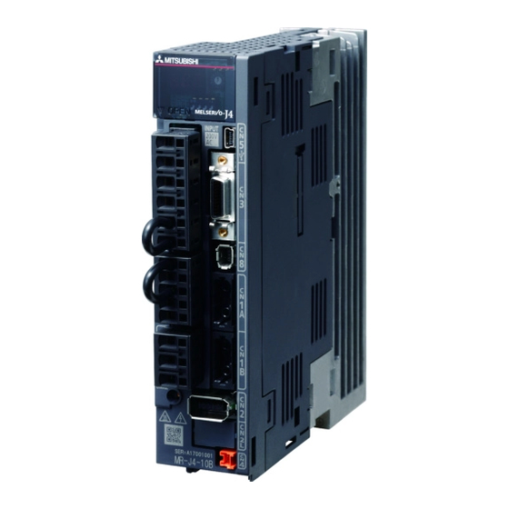
- Page 25 1 Functions and configuration 1.7 Structure 1.7.1 Parts identification (1) MR-J4-200A or less Detailed Name/Application explanati Display Section The 5-digit, seven-segment LED shows the servo status and the alarm number. Operation section Used to perform status display, diagnostic, alarm, Inside of the display cover and parameter setting operations.
- Page 26 1 Functions and configuration (2) MR-J4-350A Detailed The broken line area is the same as MR-J4-200A or less. MR-J4-200A Name/Application explanati Main circuit power supply connector (CNP1) Section Connect the input power supply. Section Rating plate Section Servo motor power supply connector (CNP3) Section Connect the servo motor.
- Page 27 1 Functions and configuration (3) MR-J4-500A POINT The servo amplifier is shown with the front cover open. The front cover cannot be removed. Detailed The broken line area is the same as MR-J4-200A or less. MR-J4-200A Name/Application explanati Control circuit terminal block (TE2) Section Used to connect the control circuit power supply.
- Page 28 1 Functions and configuration (4) MR-J4-700A POINT The servo amplifier is shown without the front cover. For removal of the front cover, refer to section 1.6.2. Detailed The broken line area is the same as MR-J4-200A or less. MR-J4-200A Name/Application explanati Power factor improving reactor terminal block (TE3) Used to connect the DC reactor.
- Page 29 1 Functions and configuration 1.7.2 Removal and reinstallation of the front cover Before removing or installing the front cover, turn off the power and wait for 15 minutes or more until the charge lamp turns off. Then, confirm that the voltage Cautions between P+ and N- is safe with a voltage tester and others.
- Page 30 1 Functions and configuration Reinstallation of the front cover Front cover setting tab 1) Insert the front cover setting tabs into the sockets of 2) Push down the cover, supporting at point A). servo amplifier (2 places). Setting tab 3) Press the cover against the terminal box until the installing knobs click.
- Page 31 (Note 2) Power supply Personal computer Molded case circuit breaker (MCCB) (Note 3) Magnetic Analog monitor contactor (MC) Personal computer (Note 4) (Note 1) To safety relay or MR-J3- D05 safety logic unit Line noise filter Junction terminal block Power factor improving DC reactor Regenerative...
- Page 32 1 Functions and configuration (2) MR-J4-350A R S T (Note 2) ( 2) Power supply Molded case circuit (MCCB) breaker (MCCB) Personal computer MR Configurator2 (Note 3) ( 3) Magnetic (MC) contactor (MC) (Note 1) ( 1) Analog monitor Personal computer (Note 4) ( 4) Line noise To safety relay or MR-J3-...
- Page 33 1 Functions and configuration (3) MR-J4-500A R S T (Note 2) ( 2) Power supply Molded case circuit breaker (MCCB) (MCCB) Personal computer MR Configurator2 (Note 3) ( 3) Magnetic contactor (MC) (MC) ( 1) (Note 1) Analog monitor Line noise Personal computer (Note 4) ( 4) filter...
- Page 34 1 Functions and configuration (4) MR-J4-700A R S T (Note 2) ( 2) Power supply Molded case circuit (MCCB) Personal breaker (MCCB) computer MR Configurator2 (Note 3) ( 3) Magnetic contactor (MC) (MC) Analog monitor (Note 1) ( 1) Personal computer (Note 4) ( 4) To safety relay or MR-J3- Line noise...
- Page 37 Cabinet Cabinet 40 mm or more Servo amplifier Wiring allowance 80 mm or more 10 mm or more 10 mm or more Bottom 40 mm or more...
- Page 38 Cabinet Cabinet 100 mm or more 100 mm or more 1 mm 1 mm 10 mm or more 30 mm 30 mm 30 mm or more or more or more Bottom 40 mm or more 40 mm or more Leaving clearance Mounting closely...
- Page 42 3. SIGNALS AND WIRING 3. SIGNALS AND WIRING Any person who is involved in wiring should be fully competent to do the work. Before wiring, turn off the power and wait for 15 minutes or more until the charge lamp turns off. Then, confirm that the voltage between P+ and N- is safe with a voltage tester and others.
- Page 43 Servo amplifier Servo motor Servo amplifier Servo motor...
- Page 44 3. SIGNALS AND WIRING (1) For 3-phase 200 V AC to 240 V AC power supply of MR-J4-10A to MR-J4-350A Malfunction EMG stop switch Servo amplifier Servo motor MCCB CNP1 MC (Note 6) MC( 6) 3-phase CNP3 (Note 5) ( 5) 200 V AC to 240V AC AC200V 240V Motor...
- Page 45 3. SIGNALS AND WIRING (2) For 1-phase 200 V AC to 240 V AC power supply of MR-J4-10A to MR-J4-70A POINT Connect the 1-phase 200 V AC to 240 V AC power supply to L1 and L3. One of the connecting destinations is different from MR-J3 Series Servo Amplifier. When using MR-J4 as a replacement for MR-J3, be careful not to connect the power to L2.
- Page 46 3. SIGNALS AND WIRING (3) MR-J4-500A Malfunction EMG stop switch Servo amplifier Servo motor MCCB MC (Note 6) MC( 6) 3-phase ( 5) (Note 5) 200 V AC to 240V AC AC200V 240V Motor (Note 9) ( 9) (Note 1) ( 1) ( 3) (Note 3)
- Page 47 3. SIGNALS AND WIRING (4) MR-J4-700A Malfunction EMG stop switch Servo amplifier Servo motor MCCB MC (Note 6) MC( 6) 3-phase (Note 5) ( 5) 200 V AC to 240V AC AC200V 240V Built-in Motor regenerative resistor (Note 2) ( 2) (Note 9) ( 9) ( 3)
- Page 48 3. SIGNALS AND WIRING 3.2 I/O signal connection example 3.2.1 Position control mode Servo amplifier 24 V DC (Note 4,12) DC24V( 4 12) (Note 7) ( 7) Positioning module QD75D (Note 7) ( 7) DICOM ( 2) (Note 2) Malfunction DICOM ( 6) (Note 6)
- Page 49 3. SIGNALS AND WIRING Note 1. To prevent an electric shock, always connect the protective earth (PE) terminal (marked ) of the servo amplifier to the protective earth (PE) of the cabinet. Connect the diode in the correct direction. If it is connected reversely, the servo amplifier will malfunction and will not output signals, disabling EM2 (Forced stop 2) and other protective circuits.
-
Page 50: Speed Control Mode
3. SIGNALS AND WIRING 3.2.2 Speed control mode Servo amplifier (Note 7) ( 7) (Note 7) ( 7) DICOM 24 V DC (Note 4) DC24V( 4) ( 2) (Note 2) Malfunction DICOM ( 6) (Note 6) (Note 14) DOCOM Main circuit power supply Zero speed ( 14) (Note 3,5) Forced stop 2... - Page 51 3. SIGNALS AND WIRING Note 1. To prevent an electric shock, always connect the protective earth (PE) terminal (marked ) of the servo amplifier to the protective earth (PE) of the cabinet. Connect the diode in the correct direction. If it is connected reversely, the servo amplifier will malfunction and will not output signals, disabling EM2 (Forced stop 2) and other protective circuits.
-
Page 52: Torque Control Mode
3. SIGNALS AND WIRING 3.2.3 Torque control mode POINT EM2 has the same function as EM1 in the torque control mode. Servo amplifier (Note 6) ( 6) (Note 6) ( 6) DICOM 24 V DC (Note 4) DC24V( 4) ( 2) (Note 2) Malfunction DICOM... - Page 53 3. SIGNALS AND WIRING Note 1. To prevent an electric shock, always connect the protective earth (PE) terminal (marked ) of the servo amplifier to the protective earth (PE) of the cabinet. Connect the diode in the correct direction. If it is connected reversely, the servo amplifier will malfunction and will not output signals, disabling EM2 (Forced stop 2) and other protective circuits.
- Page 54 3. SIGNALS AND WIRING 3.3 Explanation of power supply system 3.3.1 Signal explanations POINT For the layout of connector and terminal block, refer to chapter 9 DIMENSIONS. Symbol Connection Description destination (application) Supply the following power to L1, L2, and L3. For 1-phase 200 V AC to 240 V AC, connect the power supply to L1 and L3.
-
Page 55: Timing Chart
3. SIGNALS AND WIRING 3.3.2 Power-on sequence (1) Power-on procedure 1) Always wire the power supply as shown in above section 3.1 using the magnetic contactor with the main circuit power supply (3-phase: L1, L2, and L3, 1-phase: L1 and L3). Configure up an external sequence to switch off the magnetic contactor as soon as an alarm occurs. - Page 56 3. SIGNALS AND WIRING 3.3.3 Wiring CNP1, CNP2, and CNP3 POINT For the sizes of wires used for wiring, refer to section 11.9. MR-J3-500A or more do not have these connectors. Use the servo amplifier power supply connector for wiring CNP1, CNP2, and CNP3. (1) Connector (a) MR-J4-10A to MR-J4-100A Servo amplifier...
- Page 57 3. SIGNALS AND WIRING (2) Cable connection procedure (a) Cable making Refer to table 3.1 and 3.2 for stripped length of cable insulator. The appropriate stripped length of cables depends on their type, etc. Set the length considering their status. Insulator Core Stripped length...
- Page 58 3. SIGNALS AND WIRING 3.4 Connectors and pin assignment POINT The pin assignment of the connectors are as viewed from the cable connector wiring section. For the STO I/O signal connector (CN8), refer to chapter 13. For the CN3 connector, securely connect the shielded external conductor of the cable to the ground plate and fix it to the connector shell.
- Page 59 3. SIGNALS AND WIRING The servo amplifier front view shown is that of the MR-J4-20A or less. Refer to chapter 9 DIMENSIONS for the appearances and connector layouts of the other servo amplifiers. CN5 (USB connector) CN5(USB Refer to section 11.7. 11.7 CN3 (RS-422 connector) CN3(RS-422...
- Page 60 3. SIGNALS AND WIRING The device assignment of CN1 connector pins changes depending on the control mode. For the pins which are given parameters in the related parameter column, their devices will be changed using those parameters. (Note 1) (Note 2) I/O signals in control modes Pin No.
- Page 61 3. SIGNALS AND WIRING (Note 1) (Note 2) I/O signals in control modes Pin No. Related parameter DOCOM DOCOM DOCOM DOCOM DOCOM DOCOM DOCOM DOCOM DOCOM DOCOM DOCOM DOCOM Pr. PD28 Note 1. I: input signal, O: output signal P: position control mode, S: speed control mode, T: torque control mode, P/S: position/speed control switching mode, S/T: speed/torque control switching mode, T/P: torque/position control switching mode TLA will be available when TL (External torque limit selection) is enabled with [Pr.
-
Page 62: Signal (Device) Explanations
3. SIGNALS AND WIRING 3.5 Signal (device) explanations For the I/O interfaces (symbols in I/O division column in the table), refer to section 3.9.2. In the control mode field of the table P: position control mode, S: speed control mode, T: torque control mode : devices used with initial setting status, : devices used by setting [Pr. - Page 63 3. SIGNALS AND WIRING Control Connect Device Symbol or pin Function and application divisi mode division Forward rotation CN1-43 To start operation, turn on LSP and LSN. Turn it off to bring the motor to a DI-1 stroke end sudden stop and make it servo-locked. Setting [Pr.
- Page 64 3. SIGNALS AND WIRING Control Connect Device Symbol or pin Function and application divisi mode division Forward rotation CN1-18 This is used to select a servo motor torque generation directions. DI-1 selection The following shows the torque generation directions. (Note) Input device Torque generation direction Torque is not generated.
- Page 65 3. SIGNALS AND WIRING Control Connect Device Symbol or pin Function and application divisi mode division Proportion CN1-17 Turn PC on to switch the speed amplifier from the proportional integral type DI-1 control to the proportional type. If the servo motor at a stop is rotated even one pulse due to any external factor, it generates torque to compensate for a position shift.
- Page 66 3. SIGNALS AND WIRING Control Connect Device Symbol or pin Function and application divisi mode division Gain switching Turn on CDP to change the load to motor inertia ratio and gain values to DI-1 the values of [Pr. PB26] to [Pr. PB22] and [Pr. PB56] to [Pr. PB60]. Control switching CN1-45 «Position/speed control change mode»...
- Page 67 3. SIGNALS AND WIRING (b) Output device Connect Control Device Symbol or pin Function and application division divisi mode Malfunction CN1-48 When an alarm occurs, ALM will turn off. DO-1 When an alarm does not occur, ALM will turn on after 2.5 s to 3.5 s after power-on.
-
Page 68: Input Signal
3. SIGNALS AND WIRING Control Connect Device Symbol or pin Function and application division divisi mode Alarm code ACD0 (CN1-24) To use these signals, set " _ _ _ 1" in [Pr. PD34]. DI-1 This signal is output when an alarm occurs. When an alarm is not occurring, respective ordinary signals are output. -
Page 69: Output Signal
3. SIGNALS AND WIRING (3) Output signal Control Connect Device Symbol or pin Function and application divisi mode division Encoder A- CN1-4 These devices output pulses of encoder output set in [Pr. PA15] in the DO-2 phase pulse differential line driver type. CN1-5 (differential line In CCW rotation of the servo motor, the encoder B-phase pulse lags the... -
Page 70: Power Supply
3. SIGNALS AND WIRING (5) Power supply Symbol Connect Control Device or pin Function and application division divisi mode Digital I/F power DICOM CN1-20 Input 24 V DC (24 V DC ± 10% 500 mA) for I/O interface. The power supply input supply capacity changes depending on the number of I/O interface points CN1-21... - Page 71 3. SIGNALS AND WIRING 3.6 Detailed description of signals 3.6.1 Position control mode POINT Adjust the logic of a positioning module and command pulse as follows. Q series/L series positioning module Pr. 23 setting Command pulse logic setting Signal type Q series/L series positioning MR-J4-_A servo amplifier [Pr.
- Page 72 3. SIGNALS AND WIRING The following example shows that an input waveform has been set to the negative logic and forward/reverse rotation pulse trains by setting "0 0 1 0" in [Pr. PA13]. (OFF) (OFF) (ON) (ON) (ON) (OFF) Forward rotation pulse train (transistor) Reverse rotation pulse train (transistor) (OFF) (ON) (OFF) (ON) (OFF) (ON)
- Page 73 3. SIGNALS AND WIRING (2) INP (In-position) INP turns on when the number of droop pulses in the deviation counter falls within the preset in-position range ([Pr. PA10]). INP may turn on continuously during a low-speed operation with a large value set as the in-position range.
-
Page 74: Torque Limit
3. SIGNALS AND WIRING (5) Torque limit If the torque limit is canceled during servo-lock, the servo motor may suddenly Cautions rotate according to position deviation in respect to the command position. (a) Torque limit and torque By setting [Pr. PA11 Forward rotation torque limit] or [Pr. PA12 Reverse rotation torque limit], torque is always limited to the maximum value during operation. - Page 75 3. SIGNALS AND WIRING (Note) Input device Enabled torque limit value Limit value status CCW driving/CW CW driving/CCW regeneration regeneration Pr. PA11 Pr. PA12 Pr. PA11 > Pr. PA11 Pr. PA12 Pr. PA12 Pr. PA11 < Pr. PA12 Pr. PA11 Pr.
- Page 76 3. SIGNALS AND WIRING 3.6.2 Speed control mode (1) Speed setting (a) Speed command and speed The servo motor is run at the speeds set in the parameters or at the speed set in the applied voltage of VC (Analog speed command). A relation between VC (Analog speed command) applied voltage and the servo motor speed is as follows.
- Page 77 3. SIGNALS AND WIRING (b) SP1 (Speed selection 1), SP2 (Speed selection 2), and speed command value Select any of the speed settings by the internal speed commands 1 to 3 and by VC (Analog speed command) using SP1 (Speed selection 1) and SP2 (Speed selection 2) as follows. (Note) Input device Speed command value VC (Analog speed command)
- Page 78 3. SIGNALS AND WIRING 3.6.3 Torque control mode (1) Torque limit (a) Torque command and torque The following shows a relation between the applied voltage of TC (Analog torque command) and the torque by the servo motor. The maximum torque is generated at ±8 V. The speed at ±8 V can be changed with [Pr. PC13]. CCW direction Forward rotation (CCW) (CCW)
- Page 79 3. SIGNALS AND WIRING (b) Analog torque command offset Using [Pr. PC38], the offset voltage of 9999 mV to 9999 mV can be added to the TC applied voltage as follows. Maximum torque [Pr.PC38] [Pr.PC38] offset range -9999mV 9999mV -9999mV to 9999mV 8(-8) TC applied voltage [V] (2) Torque limit...
- Page 80 3. SIGNALS AND WIRING Normally, connect as follows. Servo amplifier (Note) DOCOM P15R Japan resistor RRS10 or equivalent RRS10 Note. This diagram is for sink I/O interface. For source I/O interface, refer to section 3.9.3. (b) Speed limit value selection Select any of the speed settings by the internal speed limits 1 to 7 and by VLA (Analog speed limit) using SP1 (Speed selection 1), SP2 (Speed selection 2), and SP3 (Speed selection 3) as follows.
- Page 81 3. SIGNALS AND WIRING 3.6.4 Position/speed control switching mode Set " _ _ _ 1" in [Pr. PA01] to switch to the position/speed control switching mode. This function is not available in the absolute position detection system. (1) LOP (control switching) Use LOP (Control switching) to switch between the position control mode and the speed control mode with an external contact.
- Page 82 3. SIGNALS AND WIRING (3) Speed setting in speed control mod (3 )Speed setting in speed control mode (a) Speed command and speed The servo motor is run at the speeds set in the parameters or at the speed set in the applied voltage of VC (Analog speed command).
-
Page 83: Speed/Torque Control Switching Mode
3. SIGNALS AND WIRING (c) SA (Speed reached) As in section 3.6.2 (2) 3.6.5 Speed/torque control switching mode Set " _ _ _ 3" in [Pr. PA01] to switch to the speed/torque control switching mode. (1) LOP (control switching) Use LOP (Control switching) to switch between the speed control mode and the torque control mode with an external contact. - Page 84 3. SIGNALS AND WIRING Normally, connect as follows. Servo amplifier (Note) DOCOM P15R Japan resistor RRS10 RRS10 or equivalent Note. This diagram is for sink I/O interface. For source I/O interface, refer to section 3.9.3. (b) Speed limit value selection Select any of the speed settings by the internal speed limit 1 and by VLA (Analog speed limit) using SP1 (Speed selection 1) as follows.
- Page 85 3. SIGNALS AND WIRING 3.6.6 Torque/position control switching mode Set " _ _ _ 5" in [Pr. PA01] to switch to the torque/position control switching mode. (1) LOP (control switching) Use LOP (Control switching) to switch between the torque control mode and the position control mode with an external contact.
-
Page 86: Connection Diagram
3. SIGNALS AND WIRING 3.7 Forced stop deceleration function POINT When alarms not related to the forced stop function occur, control of motor deceleration can not be guaranteed. (Refer to chapter 8.) In the torque control mode, the forced stop deceleration function is not available. 3.7.1 Forced stop deceleration function (SS1) When EM2 is turned off, dynamic brake will start to stop the servo motor after forced stop deceleration. - Page 87 3. SIGNALS AND WIRING (2) Timing chart POINT When LSP/LSN is turned on during a forced stop deceleration, the motor will stop depending on the setting of [Pr. PD30] as follows. [Pr. Stop system PD30] _ _ _ 0 Switching to sudden stop _ _ _ 1 Continuing forced stop deceleration When EM2 (Forced stop 2) turns off, the motor will decelerate according to [Pr.
- Page 88 3. SIGNALS AND WIRING 3.7.2 Base circuit shut-off delay time function The base circuit shut-off delay time function is used to maintain power at the motor for a specified time delay after a forced stop activation (EM2 goes off). The time between completion of EM2 (Forced stop 2) or activation of MBR (Electromagnetic brake interlock) due to an alarm occurrence, and the time at which the base is cut, is the base cut delay time and is set by [Pr.
- Page 89 3. SIGNALS AND WIRING 3.7.3 Vertical axis freefall prevention function The vertical axis freefall prevention function avoids machine damage by pulling up the shaft slightly like the following case. When the servo motor is used for operating vertical axis, the servo motor electromagnetic brake and the base circuit shut-off delay time function avoid dropping axis at forced stop.
-
Page 90: Signals And Wiring
3. SIGNALS AND WIRING 3.8 Alarm occurrence timing chart When an alarm has occurred, remove its cause, make sure that the operation Cautions signal is not being input, ensure safety, and reset the alarm before restarting operation. POINT In the torque control mode, the forced stop deceleration function is not available. To deactivate an alarm, cycle the control circuit power, push the "SET"... -
Page 91: When You Do Not Use The Forced Stop Deceleration Function
3. SIGNALS AND WIRING (2) When the forced stop deceleration function is not enabled Alarm occurrence Braking by the dynamic brake Dynamic brake Servo motor speed + Braking by the electromagnetic brake 0 r/min 0r/min Base circuit (Energy supply to the servo motor) Servo amplifier display No alarm... - Page 92 3. SIGNALS AND WIRING 3.9 Interfaces 3.9.1 Internal connection diagram POINT Refer to section 13.3.1 for the CN8 connector. Servo amplifier (Note 1) ( 1) (Note 1) ( 1) Approximately 6.2k SON SON SON DICOM SP2 SP2 16 INP SA PC ST1 RS2 17 TL ST2 RS1 18 (Note 3)
-
Page 93: Detailed Description Of Interfaces
3. SIGNALS AND WIRING Note 1. P: position control mode, S: speed control mode, T: torque control mode This is for the differential line driver pulse train input. For the open-collector pulse train input, connect as follows. DOCOM 24 V DC DC24V DICOM DOCOM... - Page 94 3. SIGNALS AND WIRING (3) Pulse train input interface DI-2 Give a pulse train signal in the differential line driver type or open-collector type. (a) Differential line driver type 1) Interface Servo amplifier Max. input pulse frequency 4Mpps( 2) 4 Mpps (Note 2) 10 m or shorter PP(NP) Approximately...
- Page 95 3. SIGNALS AND WIRING 2) Input pulse condition tLH = tHL < 0.2μs tc > 2μs tF > 3μs (4) Encoder output pulse DO-2 (a) Open-collector type Interfaces Maximum sink current: 35 mA 5 VDC to 24 V DC DC5V Servo amplifier Servo amplifier Photocoupler...
-
Page 96: Output Pulse
3. SIGNALS AND WIRING 2) Output pulse Servo motor CCW rotation Time cycle (T) is determined by the settings of (T) [Pr.PA15] [Pr.PC19] [Pr. PA15] and [Pr. PC19]. 400 s or more 400μs (5) Analog input Input impedance 10 k to 12 k Servo amplifier + 15 V DC DC + 15V... - Page 97 3. SIGNALS AND WIRING 3.9.3 Source I/O interfaces In this servo amplifier, source type I/O interfaces can be used. In this case, all DI-1 input signals and DO-1 output signals are of source type. Perform wiring according to the following interfaces. (1) Digital input interface DI-1 Servo amplifier For transistor...
- Page 98 3. SIGNALS AND WIRING 3.10 Servo motor with an electromagnetic brake 3.10.1 Safety precautions Configure an electromagnetic brake circuit so that it is activated also by an external EMG stop switch. Contacts must be opened when ALM (Malfunction) Contacts must be opened with the ALM( MBR( or MBR (Electromagnetic brake interlock) turns off.
- Page 99 3. SIGNALS AND WIRING (2) Setting (a) Enable MBR (Electromagnetic brake interlock) with [Pr. PD03] to [Pr. PD22]. (b) In [Pr. PC16 Electromagnetic brake sequence output], set the time delay (Tb) from electromagnetic brake operation to base circuit shut-off at a servo-off as in the timing chart in section 3.10.2 (1). 3.10.2 Timing chart (1) When you use the forced stop deceleration function POINT...
- Page 100 3. SIGNALS AND WIRING (b) Forced stop 2 on/off POINT In the torque control mode, the forced stop deceleration function is not available. (Note 2) ( 2) Model speed command 0 Servo motor and equal to or less than speed zero speed 0 r/min 0r/min...
- Page 101 3. SIGNALS AND WIRING (e) Main circuit power supply off during control circuit power supply on POINT In the torque control mode, the forced stop deceleration function is not available. Forced stop deceleration Dynamic brake Dynamic brake Time until voltage decrease Servo motor speed + Electromagnetic brake is detected...
- Page 102 3. SIGNALS AND WIRING (c) Alarm occurrence The operation status during an alarm is the same as section 3.8. (d) Both main and control circuit power supplies off It is the same as (1) (d) in this section. (e) Main circuit power supply off during control circuit power supply on Dynamic brake Dynamic brake + Electromagnetic brake...
- Page 103 3. SIGNALS AND WIRING 3.11 Grounding Ground the servo amplifier and servo motor securely. WARNING To prevent an electric shock, always connect the protective earth (PE) terminal (marked ) of the servo amplifier to the protective earth (PE) of the cabinet. The servo amplifier switches the power transistor on-off to supply power to the servo motor.
- Page 104 4. STARTUP 4. STARTUP Do not operate the switches with wet hands. Otherwise, it may cause an electric WARNING shock. Before starting operation, check the parameters. Improper settings may cause some machines to operate unexpectedly. The servo amplifier heat sink, regenerative resistor, servo motor, etc. may be hot while power is on or for some time after power-off.
- Page 105 4. STARTUP 4.1.2 Wiring check (1) Power supply system wiring Before switching on the main circuit and control circuit power supplies, check the following items. (a) Power supply system wiring The power supplied to the power input terminals (L1, L2, L3, L11, and L21) of the servo amplifier should satisfy the defined specifications.
- Page 106 4. STARTUP 3) When you use a brake unit and a power regenerative converter for 7 kW The lead wire of built-in regenerative resistor connected to P+ terminal and C terminal should not be connected. Brake unit, power regenerative converter or power regenerative common converter should be connected to P+ terminal and N- terminal.
-
Page 107: Power On And Off Procedures
4. STARTUP 4.2 Startup in position control mode Make a startup in accordance with section 4.1. This section provides the methods specific to the position control mode. 4.2.1 Power on and off procedures (1) Power-on Switch power on in the following procedure. Always follow this procedure at power-on. 1) Switch off SON (Servo-on). - Page 108 4. STARTUP 4.2.3 Test operation Before starting actual operation, perform test operation to make sure that the machine operates normally. Refer to section 4.2.1 for the power on and off methods of the servo amplifier. Test operation of the servo motor In this step, confirm that the servo amplifier and servo motor operate alone in JOG operation of test normally.
- Page 109 4. STARTUP 4.2.4 Parameter setting POINT The following encoder cables are of four-wire type. When using any of these encoder cables, set [Pr. PC22] to "1 _ _ _" to select the four-wire type. Incorrect setting will result in [AL. 16 Encoder initial communication error 1]. MR-EKCBL30M-L MR-EKCBL30M-H MR-EKCBL40M-H...
- Page 111 4. STARTUP (2) How to find the cause of position shift Servo amplifier Positioning module Machine (a) Output pulse Servo motor counter Electronic gear [Pr.PA05] [Pr.PA06] [Pr. PA05],[Pr. PA06], (d) Machine stop position M [Pr.PA07] [Pr.PA21] [Pr. PA07],[Pr. PA21] (b) Cumulative command pulses (C) SON (Servo-on) input (C) SON( LSP LSN(...
- Page 112 4. STARTUP 2) When P • During operation, SON (Servo-on), LSP (Forward rotation stroke end), or LSN (Reverse rotation stroke end) was switched off; or CR (Clear) or RES (Reset) was switched on. (Cause C) 3) When C • Mechanical slip occurred between the servo motor and machine. (Cause B) 4.3 Startup in speed control mode Make a startup in accordance with section 4.1.
- Page 113 4. STARTUP 4.3.3 Test operation Before starting actual operation, perform test operation to make sure that the machine operates normally. Refer to section 4.3.1 for the power on and off methods of the servo amplifier. In this step, confirm that the servo amplifier and servo motor operate Test operation of the servo motor alone in JOG operation of test normally.
- Page 114 4. STARTUP 4.3.4 Parameter setting POINT The following encoder cables are of four-wire type. When using any of these encoder cables, set [Pr. PC22] to "1 _ _ _" to select the four-wire type. Incorrect setting will result in [AL. 16 Encoder initial communication error 1]. MR-EKCBL30M-L MR-EKCBL30M-H MR-EKCBL40M-H...
- Page 115 4. STARTUP 4.3.5 Actual operation Start actual operation after confirmation of normal operation by test operation and completion of the corresponding parameter settings. 4.3.6 Trouble at start-up Never adjust or change the parameter values extremely as it will make operation CAUTION unstable.
- Page 116 4. STARTUP Start-up sequence Fault Investigation Possible cause Reference Gain adjustment Rotation ripples (speed Make gain adjustment in the Gain adjustment fault Chapter 6 fluctuations) are large following procedure. at low speed. 1. Increase the auto tuning response level. 2. Repeat acceleration and deceleration several times to complete auto tuning.
- Page 118 4. STARTUP 4.4.3 Test operation Before starting actual operation, perform test operation to make sure that the machine operates normally. Refer to section 4.4.1 for the power on and off methods of the servo amplifier. Test operation of the servo motor In this step, confirm that the servo amplifier and servo motor operate alone in JOG operation of test normally.
- Page 119 4. STARTUP 4.4.4 Parameter setting POINT The following encoder cables are of four-wire type. When using any of these encoder cables, set [Pr. PC22] to "1 _ _ _" to select the four-wire type. Incorrect setting will result in [AL. 16 Encoder initial communication error 1]. MR-EKCBL30M-L MR-EKCBL30M-H MR-EKCBL40M-H...
- Page 120 4. STARTUP 4.4.6 Trouble at start-up Never adjust or change the parameter values extremely as it will make unstable CAUTION movement. POINT Using the optional MR Configurator2, you can refer to reason for rotation failure, etc. The following faults may occur at start-up. If any of such faults occurs, take the corresponding action. Start-up sequence Fault Investigation...
- Page 121 4. STARTUP 4.5 Display and operation sections 4.5.1 Summary The MR-J4-A servo amplifier has the display section (5-digit, 7-segment LED) and operation section (4 pushbuttons) for servo amplifier status display, alarm display, parameter setting, etc. The operation section and display data are described below. 5-digit, 7-segment Displays data.
-
Page 122: Display Flowchart
4. STARTUP 4.5.2 Display flowchart Press the "MODE" button once to shift to the next display mode. Refer to section 4.5.3 and later for the description of the corresponding display mode. To refer to and set the gain/filter parameters, extension setting parameters and I/O setting parameters, make them valid with [Pr. -
Page 123: Status Display Mode
4. STARTUP 4.5.3 Status display mode The servo status during operation is shown on the 5-digit, 7-segment LED display. Press the "UP" or "DOWN" button to change display data as desired. When the required data is selected, the corresponding symbol is displayed. Press the "SET" button to display that data. At only power-on, however, data appears after the symbol of the status display selected in [Pr. - Page 124 4. STARTUP (2) Display examples The following table shows the display examples. Displayed data Item State Servo amplifier display Forward rotation at 2500 r/min Servo motor speed Reverse rotation at 3000 r/min Reverse rotation is indicated by "- ". Load to motor inertia ratio 7.00 times 11252 rev ABS counter -12566 rev...
- Page 125 4. STARTUP (3) Status display list The following table lists the servo statuses that may be shown. Refer to appendix 10 for the measurement point. Status display Symbol Unit Description Feedback pulses from the servo motor encoder are counted and displayed. The values in excess of ±99999 can be counted.
- Page 126 4. STARTUP Status display Symbol Unit Description The estimated ratio of the load inertia moment to the servo motor shaft inertia Load to motor inertia ratio Multiplier moment is displayed. Bus voltage The voltage of main circuit converter (between P+ and N-) is displayed. Encoder inside temperature °C Inside temperature of encoder etected by the encoder is displayed.
-
Page 127: Diagnostic Mode
4. STARTUP 4.5.4 Diagnostic mode Name Display Description Not ready Indicates that the servo amplifier is being initialized or an alarm has occurred. Sequence Ready Indicates that the servo was switched on after completion of initialization and the servo amplifier is ready to operate. Drive recorder enabled When an alarm occurs in the status, the drive recorder will operate and write the status of... - Page 128 4. STARTUP Name Display Description Indicates the version of the software. Software version - Lower Indicates the system number of the software. Software version - Upper If offset voltages in the analog circuits inside and outside the servo amplifier cause the servo motor to rotate slowly at VC (Analog speed command) or VLA (Analog speed limit) of 0...
-
Page 129: Alarm Mode
4. STARTUP 4.5.5 Alarm mode The current alarm, past alarm history and parameter error are displayed. The lower 2 digits on the display indicate the alarm number that has occurred or the parameter number in error. Name Display Description Indicates no occurrence of an alarm. Current alarm Indicates the occurrence of [AL. - Page 130 4. STARTUP Functions at occurrence of an alarm (1) Any mode screen displays the current alarm. (2) Even during alarm occurrence, the other screen can be viewed by pressing the button in the operation area. At this time, the decimal point in the fourth digit remains flickering. (3) For any alarm, remove its cause and clear it in any of the following methods.
-
Page 131: Parameter Mode
4. STARTUP 4.5.6 Parameter mode POINT To use the I/O setting parameters, change [Pr. PA19 Parameter writing inhibit]. (Refer to section 5.1.1) (1) Parameter mode transition After selecting the corresponding parameter mode with the "MODE" button, pushing the "UP" or "DOWN"... - Page 132 4. STARTUP (2) Operation example (a) Parameters of 5 or less digits The following example shows the operation procedure performed after power-on to change the control mode to the speed control mode with [Pr. PA01 Operation mode]. Press "MODE" to switch to the basic setting parameter screen.
- Page 133 4. STARTUP (b) Parameters of 6 or more digits The following example gives the operation procedure to change the electronic gear numerator to "123456" with [Pr. PA06 Electronic gear numerator]. Press "MODE" to switch to the basic setting parameter screen. "MODE"...
-
Page 134: Operation
4. STARTUP 4.5.7 External I/O signal display POINT The I/O signal settings can be changed using the I/O setting parameters [Pr. PD03] to [Pr. PD28]. The on/off states of the digital I/O signals connected to the servo amplifier can be confirmed. (1) Operation Call the display screen shown after power-on. - Page 135 4. STARTUP (a) Control modes and I/O signals Signal (Note 2) Symbols of I/O signals in control modes Connector Pin No. input/output Related parameter (Note 1) I/O Pr. PD03/Pr. PD04 -/SP2 SP2/SP2 SP2/- Pr. PD05/Pr. PD06 PC/ST1 ST1/RS2 RS2/PC Pr. PD07/Pr. PD08 TL/ST2 ST2/RS1 RS1/TL...
- Page 136 4. STARTUP (3) Display data at initial values (a) Position control mode CR(CN1-41) PC(CN1-17) RES(CN1-19) TL(CN1-18) SON(CN1-15) LOP(CN1-45) LSN(CN1-44) EM2(CN1-42) LSP(CN1-43) Input signal Light on: on Output signals Light off: off OP(CN1-33) RD(CN1-49) ALM(CN1-48) INP(CN1-24) ZSP(CN1-23) TLC(CN1-25) INP(CN1-22) (b) Speed control mode SP2(CN1-16) SP1(CN1-41) ST1(CN1-17)
- Page 137 4. STARTUP 4.5.8 Output signal (DO) forced output POINT When the servo system is used in a vertical lift application, turning on MBR (Electromagnetic brake interlock) by the DO forced output after assigning it to connector CN1 will release the electromagnetic brake, causing a drop. Take drop preventive measures on the machine side.
-
Page 138: Mode Switching
4. STARTUP 4.5.9 Test operation mode The test operation mode is designed for checking servo operation. Do not use it CAUTION for actual operation. If the servo motor operates unexpectedly, use EM2 (Forced stop 2) to stop it. POINT The test operation mode cannot be used in the absolute position detection system by DIO ([Pr. -
Page 139: Jog Operation
4. STARTUP (2) JOG operation POINT When performing JOG operation, turn on EM2, LSP and LSN. LSP and LSN can be set to automatic on by setting [Pr. PD01] to " _ C _ _ ". JOG operation can be performed when there is no command from the controller. (a) Operation The servo motor rotates while holding down the "UP"... - Page 140 4. STARTUP (3) Positioning operation POINT MR Configurator2 is required to perform positioning operation. Turn on EM2 (forced stop 2) when performing positioning operation. Positioning operation can be performed when there is no command from an external controller. (a) Operation a) Motor speed [r/min] Enter the servo motor speed into the "Motor speed"...
- Page 141 4. STARTUP f) Travel distance unit selection Select with the option buttons whether the travel distance set in c) is in the command pulse unit or in the encoder pulse unit. When the command input pulse unit is selected, the value, which is the set travel distance multiplied by the electronic gear, will be the command value.
- Page 142 4. STARTUP (4) Motor-less operation Without connecting the servo motor, output signals or status display can be provided in response to the input device as if the servo motor is actually running. This operation can be used to check the sequence of a programmable controller or the like.
- Page 143 4. STARTUP MEMO 4 - 40...
- Page 144 5. PARAMETERS 5. PARAMETERS Never adjust or change the parameter values extremely as it will make operation unstable. CAUTION If fixed values are written in the digits of a parameter, do not change these values. Do not change parameters for manufacturer setting. 5.1 Parameter list POINT To enable a parameter whose symbol is preceded by *, cycle the power after...
- Page 145 5. PARAMETERS 5.1.2 Gain/filter setting parameters ([Pr. PB_ _ ]) Control Initial mode Symbol Name Unit value PB01 FILT Adaptive tuning mode (adaptive filter II) 0000h Vibration suppression control tuning mode (advanced vibration PB02 VRFT 0000h suppression control II) Position command acceleration/deceleration time constant (position PB03 [ms] smoothing)
- Page 146 5. PARAMETERS Control Initial Symbol Name Unit mode value PB49 NHQ4 Notch shape selection 4 0000h PB50 Machine resonance suppression filter 5 4500 [Hz] PB51 NHQ5 Notch shape selection 5 0000h PB52 VRF21 Vibration suppression control 2 - Vibration frequency 100.0 [Hz] PB53...
- Page 147 5. PARAMETERS Control Initial Symbol Name Unit mode value COP3 PC24 Function selection C-3 0000h PC25 For manufacturer setting 0000h COP5 PC26 Function selection C-5 0000h PC27 COP6 Function selection C-6 0000h PC28 For manufacturer setting 0000h PC29 0000h PC30 STA2 Acceleration time constant 2 [ms]...
- Page 148 5. PARAMETERS Control Initial Symbol Name Unit mode value PC77 For manufacturer setting 0000h PC78 0000h PC79 0000h PC80 0000h 5.1.4 I/O setting parameters ([Pr. PD_ _ ]) Control Initial Symbol Name Unit mode value DIA1 PD01 Input signal automatic on selection 1 0000h PD02 For manufacturer setting...
- Page 150 5. PARAMETERS Control Initial Symbol Name Unit mode value PE47 For manufacturer setting 0000h PE48 0000h PE49 0000h PE50 0000h PE51 0000h PE52 0000h PE53 0000h PE54 0000h PE55 0000h PE56 0000h PE57 0000h PE58 0000h PE59 0000h PE60 0000h PE61 0.00 PE62...
-
Page 151: Detailed List Of Parameters
5. PARAMETERS Control Initial Symbol Name Unit mode value PF32 For manufacturer setting PF33 0000h PF34 0000h PF 35 0000h PF36 0000h PF37 0000h PF38 0000h PF39 0000h PF40 0000h PF41 0000h PF42 0000h PF43 0000h PF44 0000h PF45 0000h PF46 0000h PF47... - Page 152 5. PARAMETERS Initial Control Setting No./symbol/name Function value mode digit [unit] PA02 _ _ x x Regenerative option selection Used to select the regenerative option. Regenerative Incorrect setting may cause the regenerative option to burn. option If a selected regenerative option is not for use with the servo amplifier, [AL. 37 Parameter error] occurs.
- Page 153 Number of command input pulses per revolution ([Pr. PA05] "1000" to "1000000") Electronic gear selection Electronic gear (x _ _ _) ([Pr. PA21]) ([Pr. PA06]/[Pr. PA07]) (initial value) Servo motor "1" Deviation Command counter pulse train "2" Encoder Pt (servo motor resolution): 4194304 [pulse/rev]...
- Page 155 5. PARAMETERS Initial Control Setting No./symbol/name Function value mode digit [unit] PA11 You can limit the torque generated by the servo motor. Set the parameter referring 100.0 section 3.6.1 (5). The larger value of [Pr. PA11 Forward rotation torque limit value] or [Pr. PA12 Forward rotation Reverse rotation torque limit value] will be the maximum output voltage (8 V).
- Page 156 5. PARAMETERS Initial Control Setting No./symbol/name Function value mode digit [unit] PA13 Table 5.3 Command input pulse train form selection PLSS Setting For forward rotation For reverse rotation Command pulse Pulse train form value command command input form Forward rotation pulse train 0010h Reverse rotation...
- Page 157 5. PARAMETERS Control Initial Setting No./symbol/name Function value mode digit [unit] PA14 Select servo motor rotation direction relative to the input pulse train. Servo motor rotation direction Rotation Setting When forward rotation When reverse rotation direction value pulse is input pulse is input selection Forward rotation (CCW)
- Page 158 5. PARAMETERS Initial Control Setting No./symbol/name Function value mode digit [unit] PA19 Select a reference range and writing range of the parameter. 00AAh Refer to table 5.4 for settings. Parameter Table 5.4 [Pr. PA19] setting value and reading/writing range writing inhibit Setting PA19 operation...
- Page 160 5. PARAMETERS Initial Control Setting No./symbol/name Function value mode digit [unit] PB02 _ _ _ x Vibration suppression control 1 tuning mode selection VRFT Select the tuning mode of the vibration suppression control 1. Refer to section 7.1.5 for details. Vibration suppression 0: Disabled...
- Page 161 5. PARAMETERS Initial Control Setting No./symbol/name Function value mode digit [unit] PB06 This is used to set the load to motor inertia ratio. 7.00 Multiplier The setting of the parameter will be the automatic setting or manual setting (×1) depending on the [Pr. PA08] setting. Refer to the following table for details. Load to motor When the parameter is automatic setting, the value will vary between 0.00 and inertia ratio...
- Page 162 5. PARAMETERS Initial Control Setting No./symbol/name Function value mode digit [unit] PB10 This is used to set the integral time constant of the speed loop. 33.7 [ms] Decreasing the setting value will increase the response level but will be liable to generate vibration and/or noise.
- Page 163 5. PARAMETERS Initial Control Setting No./symbol/name Function value mode digit [unit] PB16 Set the shape of the machine resonance suppression filter 2. NHQ2 _ _ _ x Machine resonance suppression filter 2 selection Notch shape 0: Disabled selection 2 1: Enabled _ _ x _ Notch depth selection 0: -40 dB...
- Page 164 5. PARAMETERS Initial Control Setting No./symbol/name Function value mode digit [unit] PB18 Set the low-pass filter. 3141 [rad/s] The following shows a relation of a required parameter to this parameter. Low-pass filter setting Setting range: 100 to 18000 [Pr. PB23] [Pr.
- Page 165 5. PARAMETERS Initial Control Setting No./symbol/name Function value mode digit [unit] PB24 _ _ _ x Slight vibration suppression control selection Select the slight vibration suppression control. Slight vibration 0: Disabled suppression 1: Enabled control To enable the slight vibration suppression control, select "Manual mode (_ _ _ 3)" of "Gain adjustment mode selection"...
- Page 166 5. PARAMETERS Initial Control Setting No./symbol/name Function value mode digit [unit] PB31 Set the speed loop gain when the gain switching is enabled. [rad/s] VG2B When you set a value less than 20 rad/s, the value will be the same as [Pr. PB09]. Speed loop gain This parameter is enabled only when you select "Manual mode (_ _ _ 3)"...
- Page 167 5. PARAMETERS Initial Control Setting No./symbol/name Function value mode digit [unit] PB36 Set a dumping of the resonance frequency for vibration suppression control 1 damping 0.00 when the gain switching is enabled. VRF4B This parameter will be enabled only when the following conditions are fulfilled. Vibration suppression "Gain adjustment mode selection"...
- Page 168 5. PARAMETERS Initial Control Setting No./symbol/name Function value mode digit [unit] PB45 Table 5.7 Notch depth selection CNHF Setting Depth [dB] Setting Depth [dB] Command notch filter -40.0 -6.0 -24.1 -5.0 -18.1 -4.1 -14.5 -3.3 -12.0 -2.5 -10.1 -1.8 -8.5 -1.2 -7.2 -0.6...
- Page 169 5. PARAMETERS Initial Control Setting No./symbol/name Function value mode digit [unit] PB50 Set the notch frequency of the machine resonance suppression filter 5. 4500 [Hz] To enable the setting value, select "Enabled (_ _ _ 1)" of "Machine resonance suppression filter 5 selection" in [Pr. PB51]. Machine resonance suppression...
- Page 170 5. PARAMETERS Control Initial Setting No./symbol/name Function value mode digit [unit] PB56 Set the vibration frequency for vibration suppression control 2 when the gain switching is enabled. [Hz] VRF21B When you set a value less than 0.1 Hz, the value will be the same as [Pr. PB52]. Vibration suppression This parameter will be enabled only when the following conditions are fulfilled.
- Page 171 5. PARAMETERS Control Initial Setting No./symbol/name Function value mode digit [unit] PB60 Set the model loop gain when the gain switching is enabled. [rad/s] PG1B When you set a value less than 1.0 rad/s, the value will be the same as [Pr. PB07].
- Page 172 5. PARAMETERS Control Initial Setting No./symbol/name Function value mode digit [unit] PC03 This is used to smooth start/stop of the servo motor. [ms] Set the time of the arc part for S-pattern acceleration/deceleration. S-pattern acceleration/dec Speed command eleration time constant 0r/min 0 r/min Time...
- Page 173 5. PARAMETERS Initial Control Setting No./symbol/name Function value mode digit [unit] PC05 This is used to set speed 1 of internal speed commands. [r/min] Internal speed Setting range: 0 to permissible instantaneous speed command This is used to set speed 1 of internal speed limits. 1/internal speed limit 1 Setting range: 0 to permissible instantaneous speed...
- Page 174 5. PARAMETERS Control Initial Setting No./symbol/name Function value mode digit [unit] PC13 This is used to set the output torque at the analog torque command voltage (TC = 100.0 ±8 V) of +8 V on the assumption that the maximum torque is 100.0%. For example, set 50.0 to output at the TC = +8 V.
- Page 175 5. PARAMETERS Control Initial Setting No./symbol/name Function value mode digit [unit] PC18 _ _ _ x Alarm history clear selection Used to clear the alarm history. Alarm history 0: Disabled clear 1: Enabled When you select "Enabled", the alarm history will be cleared at next power-on. After the alarm history is cleared, the setting is automatically disabled.
- Page 176 5. PARAMETERS Control Initial Setting No./symbol/name Function value mode digit [unit] PC23 _ _ _ x Servo-lock selection at speed control stop COP2 Select the servo-lock selection at speed control stop. Function In the speed control mode, the servo motor shaft can be locked to prevent the shaft from being moved by an outer force.
- Page 177 5. PARAMETERS Initial Control Setting No./symbol/name Function value mode digit [unit] PC30 To enable the parameter, turn on STAB2 (Speed acceleration/deceleration selection). [ms] STA2 This is used to set the acceleration time required to reach the rated speed from 0 Acceleration r/min in response to VC (Analog speed command) and [Pr.
- Page 178 5. PARAMETERS Control Initial No./symbol/na Setting Function value mode digit [unit] PC36 _ _ x x Status display selection at power-on This is used to select a status display shown at power-on. Status display 00: Cumulative feedback pulse selection 01: Servo motor speed 02: Droop pulses 03: Cumulative command pulses 04: Command pulse frequency...
- Page 179 5. PARAMETERS Initial Control Setting No./symbol/name Function value mode digit [unit] PC37 This is used to set the offset voltage of VC (Analog speed command). [mV] For example, if CCW rotation is provided by switching on ST1 (Forward rotation start) with applying 0 V to VC, set a negative value. Analog speed command When automatic VC offset is used, the automatically offset value is set to this...
- Page 180 5. PARAMETERS Initial Control Setting No./symbol/name Function value mode digit [unit] PC51 This is used to set deceleration time constant when you use the forced stop deceleration function. [ms] RSBR Set the time per ms from the rated speed to 0 r/min. Forced stop deceleration Dynamic brake...
- Page 181 5. PARAMETERS 5.2.4 I/O setting parameters ([Pr. PD_ _ ]) Initial Control Setting No./symbol/name Function value mode digit [unit] PD01 Select input devices to turn on them automatically. DIA1 _ _ _ x _ _ _ x (BIN): For manufacturer setting Input signal (HEX) _ _ x _ (BIN): For manufacturer setting...
- Page 182 5. PARAMETERS Initial Control Setting No./symbol/name Function value mode digit [unit] PD03 Any input device can be assigned to the CN1-15 pin. DI1L _ _ x x Position control mode - Device selection Input device Refer to table 5.9 in [Pr. PD03] for settings. selection 1L x x _ _ Speed control mode - Device selection...
- Page 183 5. PARAMETERS Control Initial Setting No./symbol/name Function value mode digit [unit] PD08 Any input device can be assigned to the CN1-17 pin. DI3H _ _ x x Torque control mode - Device selection Input device Refer to table 5.9 in [Pr. PD03] for settings. selection 3H _ x _ _ For manufacturer setting...
- Page 184 5. PARAMETERS Control Initial Setting No./symbol/name Function value mode digit [unit] PD20 Any input device can be assigned to the CN1-44 pin. DI9H _ _ x x Torque control mode - Device selection Input device Refer to table 5.9 in [Pr. PD03] for settings. selection 9H _ x _ _ For manufacturer setting...
- Page 185 5. PARAMETERS Control Initial Setting No./symbol/name Function value mode digit [unit] PD25 _ _ x x Device selection Any output device can be assigned to the CN1-24 pin. Output device Refer to table 5.10 in [Pr. PD23] for settings. selection 3 _ x _ _ For manufacturer setting x _ _ _...
- Page 186 5. PARAMETERS Control Initial Setting No./symbol/name Function value mode digit [unit] PD34 _ _ _ x Alarm code output DOP5 This is used to select if output alarm codes. Function Alarm codes are outputted to pins CN1-22, CN1-23, and CN1-24. selection D-5 0: Disabled 1: Enabled...
- Page 187 5. PARAMETERS 5.2.6 Extension setting 3 parameters ([Pr. PF_ _ ]) Initial Control Setting mode No./symbol/name Function value digit [unit] PF21 This is used to set a drive recorder switching time. When a USB communication is cut during using a graph function, the function will be changed to the drive recorder function after the setting time of this parameter.
-
Page 188: Normal Gain Adjustment
6. NORMAL GAIN ADJUSTMENT 6. NORMAL GAIN ADJUSTMENT POINT In the torque control mode, you do not need to make gain adjustment. Before making gain adjustment, check that your machine is not being operated at maximum torque of the servo motor. If operated over maximum torque, the machine may vibrate and may operate unexpectedly. - Page 189 6. NORMAL GAIN ADJUSTMENT (2) Adjustment sequence and mode usage Start 2 gain adjustment mode 1 Interpolation made for (interpolation mode) 2 or more axes? The load fluctuation is large during driving? One-touch tuning Handle the error. Error handling is Finished normally? Auto tuning mode 1 possible?
-
Page 190: One-Touch Tuning
6. NORMAL GAIN ADJUSTMENT 6.2 One-touch tuning You can execute the one-touch tuning with MR Configurator2 or push buttons. The following parameters are set automatically with one-touch tuning. Table 6.1 List of parameters automatically set with one-touch tuning Parameter Symbol Name Parameter Symbol... - Page 191 6. NORMAL GAIN ADJUSTMENT (2) When you use push buttons Make one-touch tuning as follows. Start Startup a system referring to chapter 4. Startup of the system Rotate the servo motor by an external controller, etc. (The one-touch tuning cannot be performed if the Operation servo motor is not operating.) Push the "MODE"...
- Page 192 6. NORMAL GAIN ADJUSTMENT 6.2.2 Display transition and operation procedure of one-touch tuning (1) When you use MR Configurator2 (a) Response mode selection Select a response mode from 3 modes in the one-touch tuning window of MR Configurator2. Response mode Explanation High mode This mode is for high rigid system.
- Page 193 6. NORMAL GAIN ADJUSTMENT Response Machine characteristic mode Response Low mode Basic mode High mode Guideline of corresponding machine Low response Arm robot General machine tool conveyor Precision working machine Inserter Mounter Bonder High response 6 - 6...
- Page 194 6. NORMAL GAIN ADJUSTMENT (b) One-touch tuning execution After the response mode is selected in (a), pushing the start button during driving will start one-touch tuning. If the start button is pushed while the motor stops, "C 0 0 2" or "C 0 0 4" will be displayed at status in error code.
- Page 195 6. NORMAL GAIN ADJUSTMENT (c) One-touch tuning execution During one-touch tuning, pushing the stop button stops one-touch tuning. If the one-touch tuning is stopped, "C 0 0 0" will be displayed at status in error code. (d) If an error occur If a tuning error occurs during tuning, one-touch tuning will be forcibly terminated.
- Page 196 6. NORMAL GAIN ADJUSTMENT (g) Clearing one-touch tuning You can clear the parameter values set with one-touch tuning. Refer to table 6.1 for the parameters which you can clear. Pushing "Return to before tuning" in the one-touch tuning window of MR Configurator2 enables to rewrite the parameter to the value before pushing the start button.
- Page 197 6. NORMAL GAIN ADJUSTMENT (2) When you use push buttons (a) Response mode selection Select a response mode of the one-touch tuning from 3 modes with "UP" or "DOWN". Response mode selection display Low mode This mode is for low rigid system. Basic mode This mode is for normal system.
- Page 198 6. NORMAL GAIN ADJUSTMENT (c) One-touch tuning execution Stop symbol The one-touch tuning mode can be stopped by pushing the "SET" button regardless of displayed "SET" item. 2 s interval The stop symbol and error code "C 000" (cancel during tuning) will be displayed by turns with 2 "C 000"( ) 2s s interval.
- Page 199 6. NORMAL GAIN ADJUSTMENT (f) If a warning occur One-touch tuning in progress If a warning occurs during tuning, the alarm No. of the warning will be displayed. When the warning is one which continue the motor driving, the one-touch tuning will be continued.
- Page 200 6. NORMAL GAIN ADJUSTMENT 6.2.3 Caution for one-touch tuning (1) The tuning is not available in the torque control mode. (2) The one-touch tuning cannot be executed while an alarm or warning which does not continue the motor driving is occurring. (3) You can execute the one-touch tuning during the following test operation modes marked by "...
- Page 201 6. NORMAL GAIN ADJUSTMENT 6.3 Auto tuning 6.3.1 Auto tuning mode The servo amplifier has a real-time auto tuning function which estimates the machine characteristic (load to motor inertia ratio) in real time and automatically sets the optimum gains according to that value. This function permits ease of gain adjustment of the servo amplifier.
- Page 202 6. NORMAL GAIN ADJUSTMENT 6.3.2 Auto tuning mode basis The block diagram of real-time auto tuning is shown below. Load moment Automatic setting of inertia Encoder Loop gain Command Current PG1 PG2 control VG2 VIC Current feedback Servo motor Real-time auto tuning Position/speed Set 0 or 1 to turn on.
-
Page 203: Adjustment Procedure By Auto Tuning
6. NORMAL GAIN ADJUSTMENT 6.3.3 Adjustment procedure by auto tuning Since auto tuning is made valid before shipment from the factory, simply running the servo motor automatically sets the optimum gains that match the machine. Merely changing the response level setting value as required completes the adjustment. - Page 204 6. NORMAL GAIN ADJUSTMENT 6.3.4 Response level setting in auto tuning mode Set the response of the whole servo system by [Pr. PA09]. As the response level setting is increased, the track ability and settling time for a command decreases, but a too high response level will generate vibration. Hence, make setting until desired response is obtained within the vibration-free range.
- Page 205 6. NORMAL GAIN ADJUSTMENT 6.4 Manual mode If you are not satisfied with the adjustment of auto tuning, you can make simple manual adjustment with three parameters. POINT If machine resonance occurs, filter tuning mode selection in [Pr. PB01] or machine resonance suppression filter in [Pr.
- Page 206 6. NORMAL GAIN ADJUSTMENT (c) Parameter adjustment 1) [Pr. PB09 Speed loop gain] This parameter determines the response level of the speed control loop. Increasing this value enhances response but a too high value will make the mechanical system liable to vibrate. The actual response frequency of the speed loop is as indicated in the following expression.
- Page 207 6. NORMAL GAIN ADJUSTMENT (b) Adjustment procedure Step Operation Description Brief-adjust with auto tuning. Refer to section 6.2.3. Change the setting of auto tuning to the manual mode ([Pr. PA08]: 0 0 0 3). Set the estimated value to the load to motor inertia ratio. (If the estimate value with auto tuning is correct, setting change is not required.) Set a slightly smaller value to the model loop gain and the...
- Page 208 6. NORMAL GAIN ADJUSTMENT 3) [Pr. PB08 Position loop gain] This parameter determines the response level to a disturbance to the position control loop. Increasing the value increases the response level to the disturbance, but a too high value will increase vibration of the mechanical system.
- Page 209 6. NORMAL GAIN ADJUSTMENT 6.5 2 gain adjustment mode The 2 gain adjustment mode is used to match the position loop gains of the axes when performing the interpolation operation of servo motors of two or more axes for an X-Y table or the like. In this mode, manually set the model loop gain that determines command track ability.
- Page 210 6. NORMAL GAIN ADJUSTMENT (3) Adjustment procedure of 2 gain adjustment mode POINT Set the same value in [Pr. PB07 Model loop gain] for the axis used in 2 gain adjustment mode. Step Operation Description Select the auto tuning Set to the auto tuning mode. mode 1.
- Page 211 6. NORMAL GAIN ADJUSTMENT MEMO 6 - 24...
-
Page 212: Special Adjustment Functions
7. SPECIAL ADJUSTMENT FUNCTIONS 7. SPECIAL ADJUSTMENT FUNCTIONS POINT The functions given in this chapter need not be used normally. Use them if you are not satisfied with the machine status after making adjustment in the methods in chapter 6. 7.1 Filter setting The following filters are available with MR-J4 servo amplifiers. - Page 213 7. SPECIAL ADJUSTMENT FUNCTIONS (1) Function The machine resonance suppression filter is a filter function (notch filter) which decreases the gain of the specific frequency to suppress the resonance of the mechanical system. You can set the gain decreasing frequency (notch frequency), gain decreasing depth and width. Machine resonance point Frequency Notch width...
- Page 214 7. SPECIAL ADJUSTMENT FUNCTIONS (2) Parameter (a) Machine resonance suppression filter 1 ([Pr. PB13] and [Pr. PB14]) Set the notch frequency, notch depth and notch width of the machine resonance suppression filter 1 ([Pr. PB13] and [Pr. PB14]) When you select "Manual setting (_ _ _ 2)" of "Filter tuning mode selection" in [Pr. PB01], the setting of the machine resonance suppression filter 1 is enabled.
- Page 215 7. SPECIAL ADJUSTMENT FUNCTIONS 7.1.2 Adaptive filter II POINT The machine resonance frequency which adaptive filter II (adaptive tuning) can respond to is about 100 Hz to 2.25 kHz. As for the resonance frequency out of the range, set manually. When adaptive tuning is executed, vibration sound increases as an excitation signal is forcibly applied for several seconds.
- Page 216 7. SPECIAL ADJUSTMENT FUNCTIONS (3) Adaptive tuning mode procedure Adaptive tuning Operation Is the target response reached? Increase the response setting. Has vibration or unusual noise occurred? Execute or re-execute adaptive tuning. (Set [Pr. PB01] to "_ _ _ 1".) ([Pr.PB01] "_ _ _ 1"...
- Page 217 7. SPECIAL ADJUSTMENT FUNCTIONS 7.1.3 Shaft resonance suppression filter (1) Function When a load is mounted to the servo motor shaft, resonance by shaft torsion during driving may generate a mechanical vibration at high frequency. The shaft resonance suppression filter suppresses the vibration.
- Page 218 7. SPECIAL ADJUSTMENT FUNCTIONS 7.1.4 Low-pass filter (1) Function When a ball screw or the like is used, resonance of high frequency may occur as the response level of the servo system is increased. To prevent this, the low-pass filter is enabled for a torque command as a default.
- Page 219 7. SPECIAL ADJUSTMENT FUNCTIONS (1) Function Vibration suppression control is used to further suppress load-side vibration, such as work-side vibration and base shake. The servo motor-side operation is adjusted for positioning so that the machine does not vibrate. Servo motor-side Servo motor-side Load side Load side...
- Page 220 7. SPECIAL ADJUSTMENT FUNCTIONS (3) Vibration suppression control tuning procedure The following flow chart is for the vibration suppression control 1. For the vibration suppression control 2, set "_ _ 1 _" in [Pr. PB02] to execute the vibration suppression control tuning. Vibration suppression control tuning Operation...
- Page 222 7. SPECIAL ADJUSTMENT FUNCTIONS (a) When a vibration peak can be confirmed with machine analyzer using MR Configurator2, or external equipment. Vibration suppression control 2 - Vibration frequency (anti-resonance frequency) [Pr.PB52] Vibration suppression control 2 - Resonance frequency [Pr.PB53] Gain characteristics 300Hz Resonance of more than 300 Hz 300Hz...
- Page 223 7. SPECIAL ADJUSTMENT FUNCTIONS 7.1.6 Command notch filter POINT By using the advanced vibration suppression control II and the command notch filter, the load-side vibration of three frequencies can be suppressed. The frequency range of machine vibration, which can be supported by the command notch filter, is between 4.5 Hz and 2250 Hz.
- Page 224 7. SPECIAL ADJUSTMENT FUNCTIONS (2) Parameter Set [Pr. PB45 Command notch filter] as shown below. For the command notch filter setting frequency, set the closest value to the vibration frequency [Hz] at the load side. [Pr.PB45] Notch depth Control command from controller Depth [dB] Setting [dB]...
- Page 225 7. SPECIAL ADJUSTMENT FUNCTIONS 7.2 Gain switching function You can switch gains with the function. You can switch gains during rotation and during stop, and can use a input device to switch gains during operation. 7.2.1 Applications The following shows when you use the function. (1) You want to increase the gains during servo-lock but decrease the gains to reduce noise during rotation.
-
Page 226: Function Block Diagram
7. SPECIAL ADJUSTMENT FUNCTIONS 7.2.2 Function block diagram The control gains, load to motor inertia ratio, and vibration suppression control settings are changed according to the conditions selected by [Pr. PB26 Gain switching function] and [Pr. PB27 Gain switching condition]. [Pr.PB26] Input device (CDP) Command pulse... - Page 227 7. SPECIAL ADJUSTMENT FUNCTIONS 7.2.3 Parameter When using the gain switching function, always select "Manual mode (_ _ _ 3)" of "Gain adjustment mode selection" in [Pr. PA08 Auto tuning mode]. The gain switching function cannot be used in the auto tuning mode.
- Page 228 7. SPECIAL ADJUSTMENT FUNCTIONS (2) Switchable gain parameter Before switching After switching Loop gain Parameter Symbol Name Parameter Symbol Name Load to motor inertia ratio PB06 Load to motor inertia ratio PB29 GD2B Load to motor inertia ratio after gain switching Model loop gain PB07 Model loop gain...
- Page 229 7. SPECIAL ADJUSTMENT FUNCTIONS (c) [Pr. PB29 Load to motor inertia ratio after gain switching] Set the load to motor inertia ratio after gain switching. If the load to motor inertia ratio does not change, set it to the same value as [Pr. PB06 Load to motor inertia ratio]. (d) [Pr.
- Page 230 7. SPECIAL ADJUSTMENT FUNCTIONS 7.2.4 Gain switching procedure This operation will be described by way of setting examples. (1) When you choose switching by input device (CDP) (a) Setting Parameter Symbol Name Setting value Unit PB06 Load to motor inertia ratio 4.00 [Multiplier] PB07...
- Page 231 7. SPECIAL ADJUSTMENT FUNCTIONS (b) Switching timing chart CDP (gain switching) After-switching gain 63.4% Before-switching gain Gain switching CDT = 100ms Model loop gain Load to motor inertia ratio 4.00 10.00 4.00 Position loop gain Speed loop gain 3000 4000 3000 Speed integral compensation Vibration suppression control 1 - Vibration...
- Page 232 7. SPECIAL ADJUSTMENT FUNCTIONS (b) Switching timing chart Command pulse Droop pulses +CDL Droop pulses [pulse] After-switching gain 63.4% Before-switching gain Gain switching CDT = 100ms Load to motor inertia ratio 4.00 10.00 4.00 10.00 Position loop gain Speed loop gain 3000 4000 3000...
- Page 233 7. SPECIAL ADJUSTMENT FUNCTIONS 7.3 Tough drive function POINT Set enable/disable of the tough drive function with [Pr. PA20 Tough drive setting]. (Refer to section 5.2.1.) This function makes the equipment continue operating even under the condition that an alarm occurs. 7.3.1 Vibration tough drive function This function prevent from vibrating by resetting a filter instantaneously when machine resonance occurs due to varied vibration frequency caused machine aging.
- Page 234 7. SPECIAL ADJUSTMENT FUNCTIONS The following shows the function block diagram of the vibration tough drive function. The function detects machine resonance frequency and compare it with [Pr. PB13] and [Pr. PB15], and reset a machine resonance frequency of a parameter whose set value is closer. Filter Setting parameter Precaution...
- Page 235 7. SPECIAL ADJUSTMENT FUNCTIONS 7.3.2 Instantaneous power failure tough drive function During the instantaneous power failure tough drive, the torque may be limited due to the load conditions or the set value of [Pr. PF25 Instantaneous power failure tough drive - Detection time]. CAUTION The immunity to instantaneous power failures is increased by the instantaneous power failure tough drive function.
- Page 236 7. SPECIAL ADJUSTMENT FUNCTIONS (1) Instantaneous power failure time of the control circuit power supply > [Pr. PF25 Instantaneous power failure tough drive - Detection time] The alarm occurs when the instantaneous power failure time of the control circuit power supply exceeds [Pr.
- Page 237 7. SPECIAL ADJUSTMENT FUNCTIONS (2) Instantaneous power failure time of the control circuit power supply < [Pr. PF25 Instantaneous power failure tough drive - Detection time] Operation status differs depending on how bus voltage decrease. (a) When the bus voltage decrease lower than 158 V DC within the instantaneous power failure time of the control circuit power supply [AL.
- Page 238 7. SPECIAL ADJUSTMENT FUNCTIONS (b) When the bus voltage does not decrease lower than 158 V DC within the instantaneous power failure time of the control circuit power supply The operation continues without alarming. Instantaneous power failure time of the control circuit power supply Control circuit power supply...
- Page 239 7. SPECIAL ADJUSTMENT FUNCTIONS MEMO 7 - 28...
-
Page 240: Troubleshooting
8. TROUBLESHOOTING 8. TROUBLESHOOTING POINT Refer to MELSERVO-J4 Servo Amplifier Instruction Manual (Troubleshooting) for details of alarms and warnings. As soon as an alarm occurs, turn SON (Servo-on) off and interrupt the power. When an error occurs during operation, the corresponding alarm or warning is displayed. When the alarm or the warning occurs, refer to MELSERVO-J4 Servo Amplifier Instruction Manual (Troubleshooting) to remove the failure. - Page 241 8. TROUBLESHOOTING Alarm code Alarm deactivation Press Stop "SET" method Detail Alarm button Power Name Detail name display (Note 2, reset on the off o (RES) current (Bit 2) (Bit 1) (Bit 0) alarm screen Encoder initial communication - Receive 16.1 data error 1 Encoder initial communication - Receive...
- Page 242 8. TROUBLESHOOTING Alarm code Alarm deactivation Press Stop "SET" method Detail Alarm button Power Name Detail name display (Note 2, reset on the off o (RES) current (Bit 2) (Bit 1) (Bit 0) alarm screen 21.1 Encoder data error 1 21.2 Encoder data update error 21.3...
- Page 243 8. TROUBLESHOOTING Alarm code Alarm deactivation Press Stop "SET" method Detail Alarm button Power Name Detail name display (Note 2, reset on the off o (RES) current (Bit 2) (Bit 1) (Bit 0) alarm screen 47.1 Cooling fan stop error Cooling fan error 47.2 Cooling fan speed reduction error...
- Page 244 8. TROUBLESHOOTING Table 8.2 Warning list Detail Stop method Name Detail name display (Note 2, 3) Servo amplifier overheat warning 91.1 Main circuit device overheat warning (Note 1) 92.1 Encoder battery cable disconnection warning Battery cable disconnection warning 92.3 Battery degradation 95.1 STO1 off detection STO warning...
- Page 245 8. TROUBLESHOOTING MEMO 8 - 6...
-
Page 246: Outline Drawings
9. OUTLINE DRAWINGS 9. OUTLINE DRAWINGS 9.1 Servo amplifier (1) MR-J4-10A•MR-J4-20A [Unit: mm] 6 mounting hole (80) CNP1 CNP2 CNP3 MR-BAT6V1 (69.3) (38.5) Mass: 0.8[kg] Mounting screw Terminal Screw size: M5 Tightening torque: 3.24[N•m] CNP1 CNP2 CNP3 Approx. 40 2-M5 screw Screw size: M4 Tightening torque: 1.2 [N•m] Mounting hole process drawing... - Page 247 9. OUTLINE DRAWINGS (2) MR-J4-40A•MR-J4-60A [Unit: mm] 6 mounting hole CNP1 CNP2 CNP3 MR-BAT6V1 69.3 38.5 Mass: 1.0[kg] Mounting screw Terminal Screw size: M5 Tightening torque: 3.24[N•m] CNP1 CNP2 CNP3 Approx. 40 2-M5 screw Screw size: M4 Tightening torque: 1.2 [N•m] Mounting hole process drawing 9 - 2...
- Page 248 9. OUTLINE DRAWINGS (3) MR-J4-70A•MR-J4-100A : mm] 6 mounting hole Exhaust CNP1 CNP2 CNP3 MR-BAT6V1 Cooling fan air intake (38.5) 69.3 Mass: 1.4[kg] Mounting screw Terminal Screw size: M5 Tightening torque: 3.24[N•m] CNP1 CNP2 CNP3 Approx. 60 Screw size: M4 3-M5 screw Tightening torque: 1.2 [N•m] 42 ±...
- Page 249 9. OUTLINE DRAWINGS (4) MR-J4-200A [Unit: mm] 6 mounting hole (80) Exhaust CNP1 CNP2 CNP3 MR-BAT6V1 Cooling fan (38.5) (69.3) air intake Mass: 2.1[kg] Mounting screw Terminal Screw size: M5 Tightening torque: 3.24[N•m] CNP1 CNP2 CNP3 Approx. 90 3-M5 screw Screw size: M4 Tightening torque: 1.2 [N•m] Approx.
- Page 250 9. OUTLINE DRAWINGS (5) MR-J4-350A [Unit: mm] 6 mounting hole (80) Exhaust CNP1 CNP3 CNP2 MR-BAT6V1 Cooling fan air intake (38.5) (69.3) Mass: 2.3[kg] Mounting screw Terminal Screw size: M5 Tightening torque: 3.24[N•m] CNP1 CNP2 CNP3 Approx. 90 13 hole 3-M5 screw Mounting hole Screw size: M4...
- Page 251 9. OUTLINE DRAWINGS (6) MR-J4-500A [Unit: mm] (80) 2- 6 mounting hole 2- 6 Cooling fan exhaust MR-BAT6V1 Air intake Mass: 4.6[kg] Mounting screw Terminal Screw size M5 Screw size: M3.5 Tightening torque: 3.24[N•m] Tightening torque: 0.8 [N•m] Approx. 105 Screw size: M4 Approx.
- Page 252 9. OUTLINE DRAWINGS (7) MR-J4-700A [Unit: mm] (80) Cooling fan 2- 6 mounting hole 2- 6 exhaust MR-BAT6V1 Air intake Mass: 6.2[kg] Mounting screw Terminal Screw size: M5 Tightening torque: 3.24[N•m] N- P3 P4 Approx. 172 Approx. 6 Approx. 6 160 ±...
- Page 256 10. CHARACTERISTICS 10. CHARACTERISTICS 10.1 Overload protection characteristics An electronic thermal is built in the servo amplifier to protect the servo motor, servo amplifier and servo motor power wires from overloads. [AL. 50 Overload 1] occurs if overload operation performed is above the electronic thermal protection curve shown in fig.
- Page 257 10. CHARACTERISTICS 1000 1000 Operating Operating Servo-lock Servo-lock (Note 1, 2) Load ratio [%] (Note 1, 2) Load ratio [%] HG-KR053, HG-KR13 HG-KR23, HG-KR43, HG-KR73 HG-MR053 HG-MR13 HG-MR23, HG-MR43, HG-MR73 HG-SR51, HG-SR81, HG-SR52, HG-SR102 1000 10000 Operating 1000 Operating Servo-lock Servo-lock (Note 1) Load ratio [%] (Note 1) Load ratio [%]...
- Page 258 10. CHARACTERISTICS 10.2 Power supply capacity and generated loss (1) Amount of heat generated by the servo amplifier Table 10.1 indicates servo amplifiers' power supply capacities and losses generated under rated load. For thermal design of an enclosed type cabinet, use the values in the table in consideration for the worst operating conditions.
- Page 259 10. CHARACTERISTICS (2) Heat dissipation area for an enclosed type cabinet The enclosed type cabinet (hereafter called the cabinet) which will contain the servo amplifier should be designed to ensure that its temperature rise is within +10 C at the ambient temperature of 40 C. (With an approximately 5 C safety margin, the system should operate within a maximum 55 C limit.) The necessary cabinet heat dissipation area can be calculated by equation 10.1.
-
Page 260: Dynamic Brake Characteristics
10. CHARACTERISTICS 10.3 Dynamic brake characteristics POINT Do not use dynamic brake to stop in a normal operation as it is the function to stop in emergency. For a machine operating at the recommended load to motor inertia ratio or less, the estimated number of usage times of the dynamic brake is 1000 times while the machine decelerates from the rated speed to a stop once in 10 minutes. - Page 261 10. CHARACTERISTICS (2) Dynamic brake time constant The following shows necessary dynamic brake time constant for equation 10.2. [ms] [ms] 1000 2000 3000 4000 5000 6000 1000 2000 3000 4000 5000 6000 [r/min] [r/min] Speed [r/min] Speed [r/min] HG-MR series HG-KR series [ms] [ms]...
-
Page 262: Cable Bending Life
10. CHARACTERISTICS 10.4 Cable bending life The bending life of the cables is shown below. This graph calculated values. Since they are not guaranteed values, provide a little allowance for these values. 1 × 10 5 × 10 1 × 10 a: Long flex life encoder cable 5 ×... - Page 263 10. CHARACTERISTICS MEMO 10 - 8...
- Page 264 11. OPTIONS AND AUXILIARY EQUIPMENT 11. OPTIONS AND AUXILIARY EQUIPMENT Before connecting any option or peripheral equipment, turn off the power and wait for 15 minutes or more until the charge lamp turns off. Then, confirm that the WARNING voltage between P+ and N- is safe with a voltage tester and others. Otherwise, an electric shock may occur.
-
Page 265: Combinations Of Cable/Connector Sets
11. OPTIONS AND AUXILIARY EQUIPMENT 11.1.1 Combinations of cable/connector sets Operation panel Personal computer Servo amplifier Controller (Packed with the servo amplifier) (Note 1) ( 1) CNP1 Safety logic unit MR-J3-D05 CNP2 CN10 CNP3 Refer to the Servo Motor Instruction Manual (Vol. 3) for options for servo ( 3 ) motor power supply, electromagnetic brake, and encoder. - Page 266 11. OPTIONS AND AUXILIARY EQUIPMENT Name Model Description Applicatio Servo amplifier Supplied power connector with servo amplifiers of 1 kW or less. CNP1 CNP2 CNP3 Connector: Connector: Connector: 06JFAT-SAXGDK-H7.5 05JFAT-SAXGDK-H5.0 03JFAT-SAXGDK-H7.5 (JST) (JST) (JST) Applicable wire size: 0.8 mm to 2.1 mm (AWG 18 to 14) Insulator OD: to 3.9 mm Open tool...
-
Page 267: Configuration Diagram
11. OPTIONS AND AUXILIARY EQUIPMENT 11.1.2 MR-D05UDL3M-B STO cable This cable is for connecting an external device to the CN8 connector. Cable model Cable length Application MR-D05UDL3M-B Connection cable for the CN8 connector (1) Configuration diagram Servo amplifier MR-D05UDL3M-B (2) Internal wiring diagram CN8 connector (Note) Yellow (with black dots) -
Page 268: Regenerative Options
11. OPTIONS AND AUXILIARY EQUIPMENT 11.2 Regenerative options Do not use servo amplifiers with regenerative options other than the combinations Cautions specified below. Otherwise, it may cause a fire. 11.2.1 Combination and regenerative power The power values in the table are resistor-generated powers and not rated powers. Regenerative Power Servo Built-in... - Page 269 11. OPTIONS AND AUXILIARY EQUIPMENT 11.2.2 Selection of regenerative option (1) Rotary servo motor: Use the following method when regeneration occurs continuously in vertical motion applications or when it is desired to make an in-depth selection of the regenerative option. (a) Regenerative energy calculation tf (1 cycle) Time...
- Page 270 11. OPTIONS AND AUXILIARY EQUIPMENT (b) Losses of servo motor and servo amplifier in regenerative mode The following table lists the efficiencies and other data of the servo motor and servo amplifier in the regenerative mode. Inverse Inverse Servo amplifier C charge [J] Servo amplifier C charge [J]...
- Page 271 11. OPTIONS AND AUXILIARY EQUIPMENT 11.2.3 Parameter setting Set [Pr. PA02] according to the option to be used. [Pr. PA02] Selection of regenerative option 00: Regenerative option is not used. For servo amplifier of 100 W, regenerative resistor is not used. For servo amplifier of 0.2 kW to 7 kW, built-in regenerative resistor is used.
- Page 272 11. OPTIONS AND AUXILIARY EQUIPMENT (1) MR-J4-500A or less Always remove the wiring from across P+ - D and fit the regenerative option across P+ - C. G3 and G4 are thermal sensor's terminals. Between G3 and G4 is opened when the regenerative option overheats abnormally.
- Page 273 11. OPTIONS AND AUXILIARY EQUIPMENT (2) MR-J4-700A Always remove the wiring (across P+ - C) of the servo amplifier built-in regenerative resistor and fit the regenerative option across P+ - C. G3 and G4 are thermal sensor's terminals. Between G3 and G4 is opened when the regenerative option overheats abnormally.
- Page 274 11. OPTIONS AND AUXILIARY EQUIPMENT built-in regenerative resistor lead terminal fixing screw 11 - 11...
- Page 275 11. OPTIONS AND AUXILIARY EQUIPMENT 11.2.5 Dimensions (1) MR-RB12 [Unit: mm] TE1 terminal block Applicable wire size: 0.2 mm to 2.5 mm (AWG14 to Tightening torque: 0.5 to 0.6 [N•m] Mounting screw Screw size: M5 Tightening torque: 3.24 [N•m] Mass: 1.1 [kg] Approx.
- Page 276 11. OPTIONS AND AUXILIARY EQUIPMENT (3) MR-RB50/MR-RB51/MR-RB5N [Unit: mm] Terminal block Cooling fan mounting screw (2-M3 screw) On opposite side 7 × 14 82.5 slotted hole Terminal screw size: M4 Tightening torque: 1.2 [N•m] Mounting screw Screw size: M5 intake Tightening torque: 5.4 [N•m] Mass: 5.6 [kg] Approx.
- Page 277 11. OPTIONS AND AUXILIARY EQUIPMENT 11.3 FR-BU2 Brake unit POINT When a brake unit and a resistor unit are installed horizontally or diagonally, the heat dissipation effect diminishes. Install them on a flat surface vertically. Temperature of the resistor unit case rises to higher than +100 C. Keep cables and flammable materials away from the case.
-
Page 278: Connection Example
11. OPTIONS AND AUXILIARY EQUIPMENT 11.3.3 Connection example POINT EM2 has the same signal as EM1 in the torque control mode. Connecting PR terminal of the brake unit to P+ terminal of the servo amplifier results in brake unit malfunction. Always connect the PR terminal of the brake unit to the PR terminal of the resistor unit. - Page 279 11. OPTIONS AND AUXILIARY EQUIPMENT (b) When connecting two brake units to a servo amplifier POINT To use brake units with a parallel connection, use two sets of FR-BU2 brake unit. Combination with other brake unit results in alarm occurrence or malfunction.
- Page 280 11. OPTIONS AND AUXILIARY EQUIPMENT Emergency stop switch Servo amplifier (Note 11) ( 11) MCCB DICOM (Note 1) ( 1) Power supply DICOM DC24V 24 V DC (Note 13) ( 13) DOCOM Main circuit power supply (Note 12) ( 12) FR-BR (Note 5) ( 5)
-
Page 281: Connection Instructions
11. OPTIONS AND AUXILIARY EQUIPMENT Note 1. For power supply specifications, refer to section 1.3. For the servo amplifier of 7 kW, always disconnect the lead wire of built-in regenerative resistor, which is connected to the P+ and C terminals. Always connect between P3 and P4 terminals. -
Page 282: Control Circuit Terminal
11. OPTIONS AND AUXILIARY EQUIPMENT 2) Control circuit terminal POINT Under tightening can cause a cable disconnection or malfunction. Over tightening can cause a short circuit or malfunction due to damage to the screw or the brake unit. Sheath Core SD SD Jumper 6 mm... - Page 283 11. OPTIONS AND AUXILIARY EQUIPMENT (b) Applicable tool Servo amplifier-side crimp terminals Symbol Crimp terminal Applicable tool Manufacturer FVD5.5-S4 YNT-1210S FVD5.5-6 8-4NS YHT-8S 11.3.4 Dimensions (1) FR-BU2 Brake unit [Unit: mm] FR-BU2-15K (Screw size: M4) Rating plate 18.5 132.5 FR-BU2-30K (Screw size: M4) Rating plate...
- Page 284 11. OPTIONS AND AUXILIARY EQUIPMENT (2) FR-BR Resistor unit [Unit: mm] (Note) Control circuit (Note) terminal Main circuit terminal Approx. 35 Approx. 35 W1 ± 1 W ± 5 Note. Ventilation ports are provided on both sides and the top. The bottom is open. Approximate Resistor unit mass [kg]...
-
Page 285: Options And Auxiliary Equipment
11. OPTIONS AND AUXILIARY EQUIPMENT (2) Connection example POINT In this configuration, only the STO function is supported. The forced stop deceleration function is not available. Servo amplifier (Note 7) ( 7) Power factor improving AC reactor FR-HAL MCCB (Note 5) ( 5) Power supply 24 V DC... - Page 286 11. OPTIONS AND AUXILIARY EQUIPMENT Note 1. When not using the phase detection terminals, fit the jumpers across RX-R, SX-S and TX-T. If the jumpers remain removed, the FR-RC will not operate. For the servo amplifier of 7 kW, always disconnect the lead wire of built-in regenerative resistor, which is connected to the P+ and C terminals.
- Page 287 11. OPTIONS AND AUXILIARY EQUIPMENT (4) Mounting hole machining dimensions When the power regenerative converter is installed to an enclosed type cabinet, mount the heat generating area of the converter outside the box to provide heat generation measures. At this time, the mounting hole having the following dimensions is machined in the box.
-
Page 288: Selection Example
11. OPTIONS AND AUXILIARY EQUIPMENT 11.5 FR-CV Power regenerative common converter POINT For details of the power regenerative common converter FR-CV, refer to the FR- CV-(H) Installation Guide (IB(NA)0600075). Do not supply power to the main circuit power supply terminals (L1, L2, and L3) of the servo amplifier. -
Page 289: Connection Diagram
11. OPTIONS AND AUXILIARY EQUIPMENT When using the FR-CV, always install the dedicated stand-alone reactor (FR-CVL). Power regenerative common Dedicated stand-alone converter reactor FR-CV-7.5K(-AT) FR-CVL-7.5K FR-CV-11K(-AT) FR-CVL-11K FR-CV-15K(-AT) FR-CVL-15K FR-CV-22K(-AT) FR-CVL-22K FR-CV-30K(-AT) FR-CVL-30K FR-CV-37K FR-CVL-37K FR-CV-55K FR-CVL-55K (3) Connection diagram POINT In this configuration, only the STO function is supported. - Page 290 11. OPTIONS AND AUXILIARY EQUIPMENT Note 1. Configure a sequence that will shut off main circuit power at the follow cases. FR-CV or servo amplifier alarm occurs. EM1 (forced stop 1) turns off. For the servo amplifier, configure a sequence that will switch the servo-on after the FR-CV is ready. For the FR-CV, the RSO signal turns off when it is put in a ready-to-operate status where the reset signal is input.
- Page 291 11. OPTIONS AND AUXILIARY EQUIPMENT (b) Example of selecting the wire sizes When connecting multiple servo amplifiers, always use junction terminals for wiring the servo amplifier terminals P , N-. Also, connect the servo amplifiers in the order of larger to smaller capacities.
-
Page 292: Other Precautions
11. OPTIONS AND AUXILIARY EQUIPMENT (5) Other precautions (a) Always use the dedicated stand-alone reactor (FR-CVL) as the power factor improving reactor. Do not use the power factor improving AC reactor (FR-HAL) or Power factor improving DC reactor (FR- HEL). (b) The inputs/outputs (main circuits) of the FR-CV and servo amplifiers include high-frequency components and may provide electromagnetic wave interference to communication equipment (such as AM radios) used near them. -
Page 293: Junction Terminal Block Mr-Tb50
11. OPTIONS AND AUXILIARY EQUIPMENT 11.6 Junction terminal block MR-TB50 (1) Usage Always use the junction terminal block (MR-TB50) with the option cable (MR-J2M-CN1TBL_M) as a set. Servo amplifier Junction terminal block MR-TB50 Cable clamp Junction terminal block cable (MR-J2M-CN1TBL_M) Ground the option cable on the junction terminal block side with the cable clamp fitting (AERSBAN- ESET). - Page 294 11. OPTIONS AND AUXILIARY EQUIPMENT (4) Junction terminal block cable MR-J2M-CN1TBL_M (a) Model explanations Model: Symbol Cable length (b) Connection diagram (Servo amplifier side) (Junction terminal side) 10150-6000EL( D7650-B500FL( Signal symbol Pin No. Pin No. Position Speed Torque P15R P15R P15R DICOM DICOM...
- Page 295 11. OPTIONS AND AUXILIARY EQUIPMENT 11.7 MR Configurator2 MR Configurator2 (SW1DNC-MRC2-E) uses the communication function of the servo amplifier to perform parameter setting changes, graph display, test operation, etc. on a personal computer. (1) Specifications Item Description Project Creat/read/save/delete project, system setting, and print Parameter Parameter setting Monitor...
- Page 296 11. OPTIONS AND AUXILIARY EQUIPMENT Note 1. Windows and Windows Vista are registered trademarks of Microsoft Corporation in the United States and/or other countries. Celeron and Pentium are the registered trademarks of Intel Corporation. On some personal computers, MR Configurator2 may not run properly. ®...
-
Page 297: Mr-Bat6V1 Battery
11. OPTIONS AND AUXILIARY EQUIPMENT 11.8 Battery POINT Refer to appendix 2 and 3 for battery transportation and the new EU Battery Directive. (1) Purpose of use for MR-BAT6V1SET This battery is used to construct an absolute position detection system. Refer to section 12.3 for the fitting method, etc. -
Page 298: Selection Example Of Wires
11. OPTIONS AND AUXILIARY EQUIPMENT 11.9 Selection example of wires POINT To comply with the UL/CSA standard, use the wires shown in appendix 5 for wiring. To comply with other standards, use a wire that is complied with each standard. Selection condition of wire size is as follows. - Page 299 11. OPTIONS AND AUXILIARY EQUIPMENT (1) When using the 600 V Grade heat-resistant polyvinyl chloride insulated wire (HIV wire) Selection example of wire size when using HIV wires is indicated below. Table 11.1 Wire size selection example 1 (HIV wire) Wires [mm Servo amplifier 4) U/V/W/...
- Page 300 11. OPTIONS AND AUXILIARY EQUIPMENT 11.10 Molded case circuit breakers, fuses, magnetic contactors (recommended) (1) For main circuit power supply Always use one molded case circuit breaker and one magnetic contactor with one servo amplifier. When using a fuse instead of the molded case circuit breaker, use the one having the specifications given in this section.
- Page 301 11. OPTIONS AND AUXILIARY EQUIPMENT 2-d mounting hole (Varnish is removed from right mounting hole (face and back side).) (Note 1) 4-d mounting hole (Varnish is removed from front right mounting hole (face and back side).) (Note 1) Max. D Max.
- Page 302 11. OPTIONS AND AUXILIARY EQUIPMENT 11.12 Power factor improving AC reactors The following shows the advantages of using power factor improving AC reactor. It improves the power factor by increasing the form factor of the servo amplifier's input current. It decreases the power supply capacity. The input power factor is improved to be about 80%.
- Page 303 11. OPTIONS AND AUXILIARY EQUIPMENT Dimensions [mm] Power factor Mass Dimens Terminal Servo amplifier improving AC ions size [kg] reactor (Note) MR-J4-10A, FR-HAL-0.4K MR-J4-20A MR-J4-40A FR-HAL-0.75K MR-J4-60A, Fig. FR-HAL-1.5K MR-J4-70A 11.3 MR-J4-100A FR-HAL-2.2K (Note) MR-J4-200A FR-HAL-3.7K (Note) MR-J4-350A FR-HAL-7.5K Fig. MR-J4-500A FR-HAL-11K 11.4...
- Page 304 11. OPTIONS AND AUXILIARY EQUIPMENT 11.14 Noise reduction techniques Noises are classified into external noises which enter the servo amplifier to cause it to malfunction and those radiated by the servo amplifier to cause peripheral devices to malfunction. Since the servo amplifier is an electronic device which handles small signals, the following general noise reduction techniques are required.
- Page 305 11. OPTIONS AND AUXILIARY EQUIPMENT Noises produced Noises transmitted Noise radiated directly Route 1) by servo amplifier in the air from servo amplifier Noise radiated from the Route 2) power supply cable Noise radiated from Route 3) servo motor cable Magnetic induction Routes 4) and 5) noise...
- Page 306 11. OPTIONS AND AUXILIARY EQUIPMENT Sensor power supply Servo amplifier Instrument Receiver Sensor Servo motor Noise transmission Suppression techniques route When measuring instruments, receivers, sensors, etc. which handle weak signals and may malfunction due to noise and/or their signal cables are contained in a cabinet together with the servo amplifier or run near the servo amplifier, such devices may malfunction due to noises transmitted through the air.
- Page 307 11. OPTIONS AND AUXILIARY EQUIPMENT (2) Noise reduction techniques (a) Data line filter (recommended) Noise can be prevented by installing a data line filter onto the encoder cable, etc. For example, ZCAT3035-1330 by TDK, ESD-SR-250 by NEC TOKIN, and GRFC-13 by Kitagawa Industries are available as data line filters.
- Page 308 11. OPTIONS AND AUXILIARY EQUIPMENT (c) Cable clamp fitting AERSBAN-_SET Generally, the grounding of the shielded wire may only be connected to the connector's SD terminal. However, the effect can be increased by directly connecting the cable to an grounding plate as shown below.
- Page 309 11. OPTIONS AND AUXILIARY EQUIPMENT (d) Line noise filter (FR-BSF01/ FR-BLF) This filter is effective in suppressing noises radiated from the power supply side and output side of the servo amplifier and also in suppressing high-frequency leakage current (0-phase current). It especially affects the noises between 0.5 MHz and 5 MHz band.
- Page 310 11. OPTIONS AND AUXILIARY EQUIPMENT (e) Radio noise filter (FR-BIF) This filter is effective in suppressing noises radiated from the power supply side of the servo amplifier especially in 10 MHz and lower radio frequency bands. The FR-BIF is designed for the input only.
- Page 311 11. OPTIONS AND AUXILIARY EQUIPMENT (f) Varistor for input power supply (recommended) Varistors are effective to prevent exogenous noise and lightning surge from entering the servo amplifier. When using a varistor, connect it between each phase of the input power supply of the equipment.
- Page 312 11. OPTIONS AND AUXILIARY EQUIPMENT 11.15 Leakage current breaker (1) Selection method High-frequency chopper currents controlled by pulse width modulation flow in the AC servo circuits. Leakage currents containing harmonic contents are larger than those of the motor which is run with a commercial power supply.
- Page 313 11. OPTIONS AND AUXILIARY EQUIPMENT Table 11.3 Servo motor’s leakage current example (lgm) Servo motor power [kW] Leakage current [mA] 0.05 to 1 Table 11.4 Servo amplifier's leakage current example (Iga) Servo amplifier capacity [kW] Leakage current [mA] 0.1 to 0.6 0.75 to 3.5 0.15 Table 11.5 Leakage circuit breaker selection example...
- Page 314 11. OPTIONS AND AUXILIARY EQUIPMENT (2) Selection example Indicated below is an example of selecting a leakage current breaker under the following conditions. × 5m × 5m Servo amplifier Servo motor MR-J4-40A HG-KR43 Use a leakage current breaker designed for suppressing harmonics/surges. Find the terms of equation (11.1) from the diagram.
- Page 315 11. OPTIONS AND AUXILIARY EQUIPMENT 11.16 EMC filter (recommended) It is recommended that one of the following filters be used to comply with EN standard's EMC directive. Some EMC filters have large in leakage current. (1) Combination with the servo amplifier Recommended filter (Soshin Electric) Servo amplifier...
- Page 316 11. OPTIONS AND AUXILIARY EQUIPMENT (3) Dimensions (a) EMC filter HF3010A-UN [Unit: mm] 3-M4 4-5.5 3-M4 (41) HF3030A-UN/HF-3040A-UN [Unit: mm] Dimensions [mm] Model HF3030A-UN R3.25 length: HF3040A-UN 11 - 53...
- Page 317 11. OPTIONS AND AUXILIARY EQUIPMENT (b) Surge protector RSPD-250-U4 [Unit: mm] Resin Lead Case 41 ± 1 11 - 54...
- Page 318 General purpose programmable controller Servo amplifier Pulse train Positioning module command Pulse train command Current EEP-ROM memory position Current position Position Backed up in the case control I/O module Speed of power failure Changing control Input current position Detecting the data Detecting the Step-down...
- Page 321 [Pr. PA03] (available in the future)
- Page 322 Install a battery, and insert the plug into the CN4 connector. Install a battery, and insert the plug into the CN4 connector. While pressing the lock release lever, pull out the connector. While pressing the lock release lever, slide the MR-BAT6V1SET case toward you.
- Page 323 Cover Locking part Projection...
- Page 337 Servo motor Proximity dog DOG (Proximity dog) CR (Home position setting) 20 ms or more 20 ms or more ABSB0(ABS transmission data bit 0) Update ABSB1(ABS transmission data bit 1) CR (Home position setting) Control circuit power supply...
- Page 338 Manual feed (JOG, etc.) Servo motor CR (Home position setting) 20 ms or more ABSB0(ABS transmission data bit 0) Update ABSB1(ABS transmission data bit 1) Control circuit power supply...
- Page 358 APPENDIX App. 1 Auxiliary equipment manufacturer (for reference) Names given in the table are as of January 2012. Manufacturer Reference J.S.T. Mfg. Co., Ltd. Junkosha Purchase from Toa Electric Industry Co. Ltd., Nagoya Branch Soshin Electric Soshin Electric Co., Ltd. TE Connectivity TE Connectivity Ltd.
- Page 359 APPENDIX (c) New handling label design containing battery illustration must be used. (only air transportation) Figure. Example of Mitsubishi Label with Battery Illustration (4) Action taken by Mitsubishi The following caution will be added to the packages of the target batteries. "Containing lithium metal battery.
-
Page 360: App. 3 Symbol For The New Eu Battery Directive
Note. This symbol mark is for EU countries only. This symbol mark is according to the directive 2006/66/EC Article 20 Information for end-users and Annex II. Your MITSUBISHI ELECTRIC product is designed and manufactured with high quality materials and components which can be recycled and/or reused. -
Page 361: Machinery Directive
APPENDIX (3) Machinery directive The MR-J4 series servo amplifiers comply with the safety component laid down in the Machinery directive. Do not allow using the machine until the machine in which this servo amplifier is mounted is declared to comply with the machinery directive. App. -
Page 362: Peripheral Devices/Options
APPENDIX (4) Power supply (a) This servo amplifier can be supplied from star-connected supply with earthed neutral point of overvoltage category III set forth in EN 61800-5-1. However, when you use the neutral point of 400 V system for single phase supply, a reinforced insulating transformer is required in the power input section. - Page 363 APPENDIX (e) Use the surge protector of RSPD-250-U4 manufactured by Okaya Electric Industries. (8) Performing EMC tests When EMC tests are run on a machine and device into which the servo amplifier has been installed, it must conform to the electromagnetic compatibility (immunity/emission) standards after it has satisfied the operating environment/electrical equipment specifications.
-
Page 364: Installation
APPENDIX (2) Installation The MR-J4 series have been approved as the products which have been installed in a cabinet. The minimum cabinet size is based on 150% of each MR-J4 combination. And also, design the cabinet so that the ambient temperature in the cabinet is 55 C or less. The servo amplifier must be installed in the metal cabinet. - Page 365 APPENDIX Table: Recommended crimp terminals Servo amplifier-side crimp terminals Symbol Manufacturer (Note 2) Crimp Applicable tool terminals FVD5.5-4 YNT-1210S (Note 1) 8-4NS YHT-8S FVD2-4 YNT-1614 Note 1. Coat the crimping part with an insulation tube. Always use recommended crimp terminals or equivalent since some crimp terminals cannot be installed depending on the size.
- Page 366 APPENDIX (9) Configuration diagram Representative configuration diagram example to conform to the UL/CSA standard is shown below. The grounding wiring is excluded from the figure configuration. Malfunction EMG stop switch MCCB MCCB Servo amplifier fuse 3-phase 200 V AC to AC200V 240V 240 V AC...
- Page 367 APPENDIX App. 7 MR-J3-D05 Safety logic unit App. 7.1 Contents of the package Open packing, and confirm the content of packing. Contents Quantity MR-J3-D05 Safety logic unit Connector for CN9 1-1871940-4 (TE Connectivity) Connector for CN10 1-1871940-8 (TE Connectivity) MR-J3-D05 Installation Guide App.
- Page 368 (4) Be sure that all safety related switches, relays, sensors, etc., meet the required safety standards. The Mitsubishi Electric safety related components mentioned in this manual are certified by Certification Body as meeting the requirements of ISO/EN ISO 13849-1 Category 3, PL d and IEC/EN 61508 SIL 2.
-
Page 369: Operation Sequence
APPENDIX (7) Perform all risk assessments and safety level certification to the machine or the system as a whole. It is recommended that a Certification Body final safety certification of the system be used. (8) To prevent accumulation of multiple malfunctions, perform a malfunction check at regular intervals as deemed necessary by the applicable safety standard. - Page 370 APPENDIX App. 7.6 Maintenance and disposal MR-J3-D05 safety logic unit is equipped with LED displays to check errors for maintenance. Please dispose this unit according to your local laws and regulations. App. 7.7 Functions and configuration App. 7.7.1 Introduction The safety logic unit MR-J3-D05 has two systems in which the each system has SS1 function (delay time) and output of STO function.
- Page 371 APPENDIX App. 7.7.2 Specifications Safety logic unit model MR-J3-D05 Voltage 24 V DC Control circuit Permissible 24 V DC ± 10% power supply voltage fluctuation Power supply 0.5 (Note 1, 2) capacity Compatible 2 systems (A-axis, B-axis independent) system Shut-off input 4 points (2 point ×...
-
Page 372: System Configuration Diagram
APPENDIX App. 7.7.3 When using MR-J3-D05 with a MR-J4 series servo amplifier (1) System configuration diagram POINT The STO cable (MR-D05UDL-M) for MR-J3 series is not available. MR-J3-D05 Servo amplifier Power Magnetic supply contactor MCCB STO switch MR-D05UDL3M-B cable STO release switch CN10 Servo motor App. - Page 373 APPENDIX (2) Connection example DC24V MR-J3-D05 SDI1A+ SDI1A- Servo amplifier SDO1A+ SDO1A- STO1 STO2 CN10 SDI2A+ STOCOM STOA SDI2A- TOFB1 SRESA+ RESA TOFB2 SRESA- SDO2A+ TOFCOM SDO2A- TOFA EM2 (A-axis) EM2(A ) SDI1B+ SDI1B- Servo amplifier SDO1B+ SDO1B- STO1 STO2 CN10 SDI2B+ STOCOM...
-
Page 374: Basic Operation Example
APPENDIX (3) Description of signal and function The following table lists which operation, the forced stop deceleration or the dynamic brake, will function for each signal input or power-off. Forced stop deceleration Input signal to MR-J4 series Signal logic Description : operates Remarks servo amplifier... - Page 375 APPENDIX App. 7.8 Signal App. 7.8.1 Connector/pin assignment (1) CN8A (Note) Device Symbol Pin No. Function/application A-axis STO1 STO1A- Outputs STO1 to A-axis driving device. STO1A+ Outputs the same signal as A-axis STO2. STO state (base shutdown): Between STO1A+ and STO1A- is opened. STO release state (in driving): Between STO1A+ and STO1A- is closed.
- Page 376 APPENDIX (4) CN10 Device Symbol Pin No. Function/application division A-axis SDI2A+ Connect this device to a safety switch for A-axis driving device. DI-1 shutdown 2 SDI2A- Input the same signal as A-axis shutdown 1. STO state (base shutdown): Open between SDI2A+ and SDI2A-. STO release state (in driving): Close between SDI2A+ and SDI2A-.
- Page 377 APPENDIX (b) Digital output interface DO-1 A lamp, relay or photocoupler can be driven. Install a diode (D) for an inductive load, or install an inrush current suppressing resistor (R) for a lamp load. (Rated current: 40 mA or less, maximum current: 50 mA or less, inrush current: 100 mA or less) A maximum of 2.6 V voltage drop occurs in the MR-J3-D05.
- Page 378 APPENDIX App. 7.8.3 Wiring CN9 and CN10 connectors Handle with the tool with care when connecting wires. (1) Wire strip (a) Use wires with size of AWG 24 to 20 (0.22 mm to 0.5 mm ) (recommended electric wire: UL1007) and strip the wires to make the stripped length 7.0 mm ±...
-
Page 379: Connecting Wires
APPENDIX 2) Connecting wires a) Confirm the model number of the housing, contact and tool to be used. b) Insert the tool diagonally into the receptacle assembly. c) Insert the tool until it hits the surface of the receptacle assembly. At this stage, the tool is vertical to the receptacle assembly. - Page 380 APPENDIX (b) Using a screwdriver To avoid damaging housings and springs when wiring with screwdriver, do not put excessive force. Be cautious when connecting. 1) Adjusting screw driver Diameter: 2.3 mm ± 0.05 mm Diameter: 2.5 mm ± 0.05 mm Length: 120 mm or less Length: 120 mm or less Width: 2.3 mm, Blade thickness: 0.25 mm...
- Page 381 APPENDIX (3) Connector insertion Insert the connector all the way straight until you hear or feel clicking. When removing the connector, depress the lock part completely before pulling out. If the connector is pulled out without depressing the lock part completely, the housing, contact and/or wires may be damaged. (4) Compatible wire Compatible wire size is listed below.
- Page 382 APPENDIX App. 7.9 LED display I/O status, malfunction and power on/off are displayed with LED for each A-axis and B-axis. Description Column Column Monitor LED for start/reset Off: The start/reset is off. (The switch contact is SRES opened.) On: The start/reset is on. (The switch contact is closed.) Monitor LED for shut-off 1 Off: The shut-off 1 is off.
- Page 383 APPENDIX App. 7.11 Troubleshooting When power is not supplied or FAULT LED turns on, refer the following table and take the appropriate action. Event Description Cause Action Power is not supplied. Power LED does not turn on 1. 24 V DC power supply is Replace the 24 V DC power supply.
- Page 384 APPENDIX App. 7.13 Installation Follow the instructions in this chapter and install MR-J3-D05 in the specified direction. Leave clearances between MR-J3-D05 and other equipment including the cabinet. Cabinet Cabinet Cabinet 40 mm 40mm 100 mm or longer 100mm or longer 80 mm or longer for 10 mm or longer 10mm...
- Page 385 APPENDIX App. 7.14 Combinations of cable/connector POINT The STO cable (MR-D05UDL-M) for MR-J3 series is not available. Servo amplifier MR-J3-D05 Servo amplifier CN10 MR-J3-D05 MR-J3-D05 attachment connector Connector MR-J3-D05 attachment connector Connector for CN9: 1-1871940-4 Connector for CN10: 1-1871940-8 (TE Connectivity) (TE Connectivity) STO cable Connector set: 2069250-1...
- Page 386 APPENDIX App. 8 EC declaration of conformity The MR-J3-D05 safety logic unit complies with the safety component laid down in the Machinery directive. App. - 29...
-
Page 387: Set Content
APPENDIX App. 9 Analog monitor The servo status can be output to two channels in terms of voltage. (1) Setting Change the following digits of [Pr. PC14] and [Pr. PC15]. [Pr. PC14] [Pr.PC14] Analog monitor 1 output selection (the signal provided to the output across MO1 and LG) (MO1-LG [Pr. - Page 388 APPENDIX Setting Setting Output item Description Output item Description value value Servo motor-side Servo motor-side CCW direction CCW direction 10 [V] 10 [V] 10[V] 10[V] droop pulses droop pulses (Note 1, 3, 5) (Note 1, 3, 5) (±10 V/100 pulses) 100 [pulse] (±10 V/1000 pulses) 100[pulse]...
- Page 389 APPENDIX (3) Analog monitor block diagram Speed Speed Current Droop pulses Bus voltage command command 2 command Current encoder Speed command Current Position Speed Command pulse Servo motor control control control Encoder inside temperature Current feedback Encoder Differen- tiation Position feedback Servo motor Feedback Torque...
- Page 394 MODEL MR-J4-A INSTRUCTIONMANUAL MODEL 1CW804 CODE HEAD OFFICE : TOKYO BLDG MARUNOUCHI TOKYO 100-8310 This Instruction Manual uses recycled paper. SH (NA) 030107-A (1203) MEE Printed in Japan Specifications subject to change without notice.
- Page 396 Phone: +380 (0)44 / 490 92 29 Fax: +380 (0)44 / 248 88 68 Mitsubishi Electric Europe B.V. /// FA - European Business Group /// Gothaer Straße 8 /// D-40880 Ratingen /// Germany Tel.: +49(0)2102-4860 /// Fax: +49(0)2102-4861120 /// info@mitsubishi-automation.com /// www.mitsubishi-automation.com...
Need help?
Do you have a question about the MELSERVO-J4 MR-J4 A Series and is the answer not in the manual?
Questions and answers