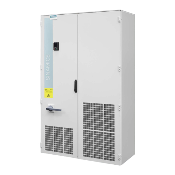
Siemens Sinamics G120P Operating Instructions Manual
Converter cabinet units 110 kw - 400 kw
Hide thumbs
Also See for Sinamics G120P:
- Instruction manual (100 pages) ,
- Technical manual (98 pages) ,
- Hardware installation manual (90 pages)
Table of Contents
Advertisement
Quick Links
Advertisement
Table of Contents

Related Manuals for Siemens Sinamics G120P


Summary of Contents for Siemens Sinamics G120P
- Page 3 ___________________ Inverter cabinet units Preface ___________________ Safety information ___________________ SINAMICS Device overview ___________________ Mechanical installation SINAMICS G120 Inverter cabinet units ___________________ Electrical installation ___________________ Commissioning Operating Instructions ___________________ Operation ___________________ Functions ___________________ Application examples ___________________ Alarms, faults and system messages ___________________ Maintenance and servicing ___________________...
- Page 4 Note the following: WARNING Siemens products may only be used for the applications described in the catalog and in the relevant technical documentation. If products and components from other manufacturers are used, these must be recommended or approved by Siemens. Proper transport, storage, installation, assembly, commissioning, operation and maintenance are required to ensure that the products operate safely and without any problems.
-
Page 5: Preface
Preface Structure of this documentation The customer documentation comprises general and individual documentation. The general documentation describes the topics that apply to all cabinet units: ● Operating Instructions The Operating Instructions consist of the following sections: – Device description – Mechanical installation –... - Page 6 The instructions for supplier components installed in the ordered cabinet unit are included as original documentation. Documentation on the Internet The documentation for SINAMICS G120 can be found on the Internet at: http://support.automation.siemens.com/WW/view/en/38797189/133300 Technical support Time zone Europe/Africa Phone +49 (0) 911 895 7222...
- Page 7 Preface EMC limit values for South Korea The EMC limit values that have to be observed for South Korea correspond to the limit values of the EMC product standard for variable-speed electric drives EN 61800-3 of category C2 or the limit value class A, Group 1 according to EN 55011. With suitable additional measures the limit values according to category C2 or to limit class A, Group 1, are maintained.
- Page 8 Preface Inverter cabinet units Operating Instructions, 12/2014, A5E32923362A...
-
Page 9: Table Of Contents
Table of contents Preface ..............................5 Safety information ..........................17 General safety instructions ..................... 17 Safety instructions for electromagnetic fields (EMF) .............. 20 Handling electrostatic sensitive devices (ESD) ..............20 Residual risks of power drive systems ..................21 Device overview ............................ 23 Section content ........................ - Page 10 Table of contents Electrical installation ..........................51 Section content ........................51 Checklist for electrical installation ..................52 Important safety precautions ....................56 Introduction to EMC ....................... 57 EMC compliant design ......................59 Power connections ......................... 61 4.6.1 Cable lugs ..........................62 4.6.2 Connection cross-sections, cable lengths ................
- Page 11 Table of contents STARTER commissioning tool ..................... 142 5.4.1 Installing STARTER ......................143 5.4.2 Explanations regarding the STARTER user interface ............144 Procedure for commissioning via STARTER ................ 145 5.5.1 Creating the project ....................... 145 5.5.2 Configure the drive unit ......................152 5.5.3 Commissioning the drive unit ....................
- Page 12 Table of contents 6.8.2.3 User data range of the USS telegram .................. 221 6.8.2.4 USS parameter channel (PIV) ..................... 222 6.8.2.5 USS process data channel (PZD) ..................227 6.8.2.6 Time-out and other errors ....................227 6.8.3 Communication over Modbus RTU ..................230 6.8.3.1 Basic settings for communication ..................
- Page 13 Table of contents Functions ............................335 Section content ........................335 Inverter control ........................335 7.2.1 Switching the motor on and off ..................... 335 7.2.2 Two-wire control, method 1 ....................338 7.2.3 Two-wire control, method 2 ....................339 7.2.4 Two-wire control, method 3 ....................340 7.2.5 Three-wire control, method 1 ....................
- Page 14 Table of contents 7.7.4 Flying restart ........................385 7.7.5 Efficiency optimization ......................386 7.7.6 Automatic restart ........................387 7.7.7 Technology controller ......................391 7.7.8 Free technology controllers ....................393 7.7.9 System protection ........................ 393 7.7.9.1 No-load monitoring, blocking protection, stall protection ............. 394 7.7.9.2 Load monitoring ........................
- Page 15 Table of contents Technical specifications ........................469 11.1 Section content ........................469 11.2 General data ......................... 469 11.2.1 Derating data ........................471 11.2.1.1 Permissible output current as a function of the ambient temperature ........471 11.2.1.2 Derating values for installation altitudes between 1000 m and 4000 m above sea level ..471 11.2.1.3 Derating factor of the output current as a function of the line voltage ........
- Page 16 Table of contents Inverter cabinet units Operating Instructions, 12/2014, A5E32923362A...
-
Page 17: Safety Information
Safety information General safety instructions DANGER Danger to life due to live parts and other energy sources Touching live parts can result in death or severe injury. • Only work on electrical equipment if you are appropriately qualified. • Always observe the country-specific safety rules for all work. Generally, six steps apply when establishing safety: 1. - Page 18 Safety information 1.1 General safety instructions WARNING Danger to life when live parts are touched on damaged devices Improper handling of devices can cause damage. For damaged devices, hazardous voltages can be present at the enclosure or at exposed components; if touched, this can result in death or severe injury. •...
- Page 19 Safety information 1.1 General safety instructions WARNING Danger to life through unexpected movement of machines when using mobile wireless devices or mobile phones Using mobile radios or mobile phones with a transmit power > 1 W closer than approx. 2 m to the components may cause the devices to malfunction, influence the functional safety of machines therefore putting people at risk or causing material damage.
-
Page 20: Safety Instructions For Electromagnetic Fields (Emf)
Safety information 1.2 Safety instructions for electromagnetic fields (EMF) Safety instructions for electromagnetic fields (EMF) WARNING Danger to life from electromagnetic fields Electromagnetic fields (EMF) are generated by the operation of electrical power equipment such as transformers, inverters or motors. People with pacemakers or implants are at a special risk in the immediate vicinity of these devices/systems. -
Page 21: Residual Risks Of Power Drive Systems
Safety information 1.4 Residual risks of power drive systems Residual risks of power drive systems Residual risks of power drive systems The control and drive components of a drive system are approved for industrial and commercial use in industrial line supplies. Their use in public line supplies requires a different configuration and/or additional measures. - Page 22 Safety information 1.4 Residual risks of power drive systems 3. Hazardous shock voltages caused by, for example: – Component malfunctions – Influence of electrostatic charging – Induction of voltages in moving motors – Operating and/or ambient conditions not within the scope of the specification –...
-
Page 23: Device Overview
Device overview Section content This chapter provides information on the following: ● Introduction to the cabinet units ● The main components and features of the cabinet unit ● The cabinet unit wiring ● Explanation of the type plate Inverter cabinet units Operating Instructions, 12/2014, A5E32923362A... -
Page 24: Applications, Features
The accuracy of sensorless vector control ensures that the system can be used for a wide variety of applications and, as a result, an additional speed sensor is not required. The SINAMICS G120P Cabinet takes this into account and, as a result, offers a low-cost drive solution tailored to actual requirements. -
Page 25: Design
Detailed contact information and the current link to our website can be found in the preface. Design The SINAMICS G120P Cabinet units are characterized by their compact, modular, and service-friendly design. A wide range of electrical and mechanical components enable the drive system to be optimized for the appropriate requirements. -
Page 26: Enclosed Drive Type A
Device overview 2.3 Design 2.3.1 Enclosed drive type A Type A permits the installation of all available line supply connection components, such as the main circuit breaker, main contactor, line fuses, radio interference suppression filter, motor components, and additional protection and monitoring devices. The cabinet drive consists of a cabinet panel with a total width of 1000 mm or 1200 mm. -
Page 27: Enclosed Chassis Type C
Device overview 2.3 Design 2.3.2 Enclosed chassis type C Type C has a particularly compact design with integrated power choke and the possibility of integrating a main circuit breaker with fuses. This very small model can be used, for example, when the necessary line supply connection components are inserted in a central low-voltage distribution present in the system. -
Page 28: Wiring Principle
Device overview 2.4 Wiring principle Wiring principle Circuit principle, types A and C Figure 2-3 Circuit principle, types A and C Inverter cabinet units Operating Instructions, 12/2014, A5E32923362A... -
Page 29: Type Plate
Device overview 2.5 Type plate Type plate Specifications on the type plate Figure 2-4 Type plate for the cabinet unit Inverter cabinet units Operating Instructions, 12/2014, A5E32923362A... - Page 30 Device overview 2.5 Type plate Type plate specifications (from type plate above) Position Specification Value Explanation ① Input 3-phase Three-phase connection 380 - 480 V Rated input voltage 50 - 60 Hz Mains frequency 750 A Rated input current ② Output 3-phase Three-phase connection...
- Page 31 Device overview 2.5 Type plate Explanation of the option short codes Table 2- 2 Explanation of the option short codes Type Type Line-side options Line filter for use in the first environment to EN 61800-3, category C2 (TN/TT sys- ✓ −...
- Page 32 Device overview 2.5 Type plate Type Type Documentation (standard: English/German) Customer documentation (circuit diagram, terminal diagram, layout diagram) in DXF ✓ ✓ format Customer documentation as hard copy ✓ ✓ Draft of customer documentation ✓ ✓ Documentation language: English/French ✓ ✓...
-
Page 33: Mechanical Installation
Mechanical installation Section content This chapter provides information on the following: ● The conditions for transporting, storing, and installing the cabinet unit ● Preparing and installing the cabinet unit Transport, storage Transportation WARNING Danger to life due to improper transporting of the unit The unit can tip over if you transport it incorrectly –... - Page 34 • If you fail to contact them immediately, you may lose your right to claim compensation for the defects and damage. • If necessary, you can request the support from your local Siemens office. Storage The devices must be stored in clean, dry rooms. Temperatures between -25° C and +55° C are permissible (class 1K4 according to EN 60721-3-1).
- Page 35 Mechanical installation 3.2 Transport, storage NOTICE Material damage resulting from switching on the device without forming the DC-link capacitors After a storage duration exceeding two years, switching on the device without forming the DC-link capacitors can cause it to become damaged. •...
-
Page 36: Assembly
Mechanical installation 3.3 Assembly Assembly WARNING Danger to life if the general safety instructions and remaining risks are not carefully observed If the general safety instructions and remaining risks are not observed, accidents can occur involving severe injuries or death. •... -
Page 37: Preparation
Mechanical installation 3.3 Assembly 3.3.2 Preparation 3.3.2.1 Requirements for installation location The cabinet units are designed for installation in closed, electrical operating areas in compliance with EN 61800-5-1. A closed electrical operating area is a room or area containing electrical equipment that can be accessed by trained personnel only. Access is controlled by a door or other form of barrier that can be opened only by means of a key or other tool. -
Page 38: Requirements On The Levelness Of The Floor
Mechanical installation 3.3 Assembly 3.3.2.2 Requirements on the levelness of the floor The foundation at the installation location must be horizontal and level, to ensure proper functioning of the cabinet units. ● Care must be taken to ensure that the doors can be opened and closed and that the locking systems work properly. -
Page 39: Shipping And Handling Indicators
Mechanical installation 3.3 Assembly 3.3.2.3 Shipping and handling indicators The cabinet units are equipped with tilt and shock indicators to monitor for damage during transit. Figure 3-2 Tilt indicator Figure 3-3 Shock indicator Position of the shipping and handling monitors The tilt indicators are affixed to the top of the cabinet unit inside the doors. - Page 40 Mechanical installation 3.3 Assembly Checking the shipping and handling monitors prior to commissioning It is essential to check the shipping and handling monitors prior to commissioning the inverter. Figure 3-4 Tilt indicator tripped The tilt indicator provides immediate visible evidence of whether the cabinet units have been handled and stored upright.
-
Page 41: Unpacking
Mechanical installation 3.3 Assembly Removing the shipping and handling monitors prior to commissioning NOTICE Material damage caused by transport indicators remaining in the device during operation If transport indicators remain in the device during operation, material damage can result from falling off or through temperature damage. •... -
Page 42: Installation
Mechanical installation 3.3 Assembly 3.3.3 Installation 3.3.3.1 Lifting the cabinet off the transport pallet Lifting the cabinet off the transport pallet The applicable local guidelines regarding the transportation of the cabinet from the transport palette to the installation location must be observed. A crane transport assembly is fitted to the top of the cabinet. - Page 43 Mechanical installation 3.3 Assembly Figure 3-7 Transport pallet, position of the mounting bolts, example for cabinet unit with base section For cabinet units without base section, the mounting bolts of the transport pallets must be removed from the bottom of the pallet. For cabinet units with base section, the mounting bolts of the transport pallet are accessible only after the cover has been removed.
-
Page 44: Disassembling The Crane Transport Assembly
Mechanical installation 3.3 Assembly Center of gravity of the cabinet The diagram below shows the center of gravity of the cabinet (for all sizes), which must always be taken into account when lifting and installing the cabinet. Figure 3-8 Center of gravity of the cabinet Note Center of gravity of the cabinet A label with the precise position of the center of gravity of the cabinet is attached to each... -
Page 45: Connection To The Foundation
Mechanical installation 3.3 Assembly Removal The crane eyebolts can be unscrewed and removed. Depending on the length of the cabinet or transport unit, the support rails can have a varying number of fastening screws. These must be unscrewed and removed before the rails can be removed. WARNING Danger of an accident occurring due to improper handling of carrying rails The improper handling of heavy carrying rails during disassembly can cause injuries or... -
Page 46: Assembly Of The Air Deflectors For Ip20 Degree Of Protection And Type A
Mechanical installation 3.3 Assembly 3.3.4 Assembly of the air deflectors for IP20 degree of protection and type A Type A cabinet drives with size GX Power Modules of IP20 degree of protection are delivered with an additional air deflector for a correct airflow. This must be fitted after the cabinet has been assembled. -
Page 47: Fitting Additional Canopies (Option M21) Or Hoods (Option M23, M43, M54)
Mechanical installation 3.3 Assembly 3.3.5 Fitting additional canopies (option M21) or hoods (option M23, M43, M54) To increase the degree of protection of the cabinets from IP20 (standard) to IP21, IP23, IP43, or IP54, additional canopies or hoods are supplied. These must be fitted once the cabinets have been installed. - Page 48 Mechanical installation 3.3 Assembly Mounting a canopy to increase the degree of protection to IP21 (option M21) Figure 3-12 Mounting of a canopy for type C Figure 3-13 Mounting of a canopy for type A Inverter cabinet units Operating Instructions, 12/2014, A5E32923362A...
- Page 49 Mechanical installation 3.3 Assembly The canopy is mounted to the cabinet roof using the original roof screws. An additional vertical partition is mounted for type A cabinets so that the hot air from the right-hand cabinet panel cannot be drawn into the left-hand cabinet panel. 1.
- Page 50 Mechanical installation 3.3 Assembly Figure 3-15 Mounting a hood The hood is mounted to the cabinet roof using the original roof screws. 1. Remove the original roof screws and any crane transport assemblies. 2. Only for hoods of options M43 and M54 : Use the provided sealing tape to attach the contact surfaces of the hood.
-
Page 51: Electrical Installation
Electrical installation Section content This section provides information on the following: ● Establishing the electrical connections for the cabinet unit ● The interfaces of the cabinet unit ● The interfaces of the additional options Inverter cabinet units Operating Instructions, 12/2014, A5E32923362A... -
Page 52: Checklist For Electrical Installation
Electrical installation 4.2 Checklist for electrical installation Checklist for electrical installation Use the following checklist to guide you through the electrical installation procedure for the cabinet unit. Read the "Safety instructions" section at the start of these Operating Instructions before you start working on the device. Note Checking the checklist Check the boxes in the "Available"... - Page 53 Electrical installation 4.2 Checklist for electrical installation Item Activity Available Completed Power connections The line-side and motor-side power cables must be dimensioned and routed in accordance with the ambient and routing conditions. The maximum permissible cable lengths between the inverter and motor must be observed depending on the type of cable used (see "Electrical installation / Power connections / Connection cross-sections and cable lengths").
- Page 54 Electrical installation 4.2 Checklist for electrical installation Item Activity Available Completed Signal connections Cabinet unit operation by higher-level controller / control room. The control cables must be connected in accordance with the interface assignment and the shield ap- plied. Taking into account electrical interference and the distance from power ca- bles, the digital and analog signals must be routed with separate cables.
- Page 55 Electrical installation 4.2 Checklist for electrical installation Item Activity Available Completed Option L60 EMERGENCY STOP category 1 stops the drive in a controlled manner. It may be necessary to use braking units because of the EMERGENCY load characteristic and the required shutdown times. No addition- STOP category al wiring is necessary when implemented in conjunction with 1, 24 VDC...
-
Page 56: Important Safety Precautions
Electrical installation 4.3 Important safety precautions Important safety precautions WARNING Danger to life if the general safety instructions and remaining risks are not carefully observed If the general safety instructions and remaining risks are not observed, accidents can occur involving severe injuries or death. •... -
Page 57: Introduction To Emc
Electrical installation 4.4 Introduction to EMC Introduction to EMC What is meant by EMC? Electromagnetic compatibility (EMC) describes the capability of an electrical device to function satisfactorily in an electromagnetic environment without itself causing interference unacceptable for other devices in the environment. EMC therefore represents a quality feature for the ●... - Page 58 Electrical installation 4.4 Introduction to EMC Noise emissions Product standard EN 61800–3 outlines the EMC requirements for variable-speed drive systems. It specifies requirements for converters with operating voltages of less than 1000 V. Different environments and categories are defined depending on where the drive system is installed.
-
Page 59: Emc Compliant Design
Electrical installation 4.5 EMC compliant design Table 4- 2 Definition of categories C1 ... C4 Definition of categories C1 ... C4 Category C1 Rated voltage <1000 V; unrestricted use in the first environment. Category C2 Rated voltage for stationary drive systems <1000 V; for use in the second environment. - Page 60 Electrical installation 4.5 EMC compliant design Use anti-interference elements ● If relays, contactors, and inductive or capacitive loads are connected, the switching relays or contactors must be provided with anti-interference elements. Cable installation ● Cables that are subject to or sensitive to interference should be laid as far apart from each other as possible.
-
Page 61: Power Connections
Electrical installation 4.6 Power connections I/O interfacing ● Create a low-impedance ground connection for additional cabinets, system components, and distributed devices with the largest possible cross-section (at least 16 mm²). ● Ground unused lines at one end in the cabinet. ●... -
Page 62: Cable Lugs
Electrical installation 4.6 Power connections 4.6.1 Cable lugs Cable lugs The cable connections on the devices are designed for cable lugs according to DIN 46234 or DIN 46235. For connection of alternative cable lugs, the maximum dimensions are listed in the table below. -
Page 63: Connection Cross-Sections, Cable Lengths
Cable lengths The maximum permissible cable lengths are specified for standard cable types or cable types recommended by SIEMENS. Longer cables can only be used after consultation. The listed cable length represents the actual distance between the inverter and the motor, taking into account factors such as parallel laying, current-carrying capacity, and the laying factor. -
Page 64: Connecting The Motor And Power Cables
Electrical installation 4.6 Power connections 4.6.3 Connecting the motor and power cables Connecting the motor and power cables on the cabinet unit Note Position of the connections For the position of the connections, see the layout diagrams. 1. Open the cabinet, remove the covers (if necessary) in front of the connection panel for motor cables (terminals U2/T1, V2/T2, W2/T3;... - Page 65 Note Siemens motors with 2 shaft ends For Siemens motors with two shaft ends, the drive side (DS) is the shaft end nearest to the terminal box. For clockwise rotation, the electric motor must be connected according to the following table.
- Page 66 Electrical installation 4.6 Power connections Note Information on the phase sequence If the motor was connected with an incorrect direction of phase rotation, it can be corrected without replacement of the phase sequence via p1820 (reverse output phase sequence). With motors that can be star-connected or delta-connected, it must be ensured that the windings are interconnected consistent with the operating voltage indicated on the type plate or in the motor documentation.
-
Page 67: Open The Connection Clip To The Basic Interference Suppression Module For Operation On An Ungrounded Line Supply (It System)
Electrical installation 4.6 Power connections 4.6.4 Open the connection clip to the basic interference suppression module for operation on an ungrounded line supply (IT system) If the cabinet unit is operated from a non-grounded supply (IT system), the connection to the basic interference suppression module of the Power Module must be opened. - Page 68 Electrical installation 4.6 Power connections Figure 4-5 Opening the left-hand housing flap Inverter cabinet units Operating Instructions, 12/2014, A5E32923362A...
- Page 69 Electrical installation 4.6 Power connections Figure 4-6 Opening the connection to the basic interference suppression module, frame size GX The connection is opened as follows: ① 1. Release the left-hand housing flap by rotating latch and opening the housing flap. ②...
-
Page 70: External Supply Of The Auxiliary Supply From A Secure Line
Electrical installation 4.7 External Supply of the Auxiliary Supply from a Secure Line External Supply of the Auxiliary Supply from a Secure Line Description An external auxiliary supply is always required when the communication and closed-loop control are to be independent of the supply system. An external auxiliary supply is particularly recommended for low-power lines susceptible to short-time voltage dips or power failures. -
Page 71: 230 Vac Auxiliary Supply
Electrical installation 4.8 Signal connections 4.7.1 230 VAC auxiliary supply The fuse must not exceed 16 A. The connection is protected inside the cabinet with a 3 A fuse. Connecting ● On terminal block -X40, remove the jumpers between terminals 1 and 2 as well as 3 and 4. ●... -
Page 72: Cu230P-2 Pn Control Unit (Option K96)
Electrical installation 4.8 Signal connections 4.8.1.1 CU230P-2 PN Control Unit (option K96) Connection overview ① ⑥ Memory card slot Switch for AI0 and AI1 (voltage/current) ② ⑦ Address switch for the fieldbus (not for USB interface for connection to a PC CU230P-2 PN) ③... - Page 73 Electrical installation 4.8 Signal connections Figure 4-8 X150 - CU230P-2 PN interfaces (view from below) The X150 P1 and P2 interfaces for connection to PROFINET are located on the device lower side. Inverter cabinet units Operating Instructions, 12/2014, A5E32923362A...
- Page 74 Electrical installation 4.8 Signal connections Connection example Figure 4-9 CU230P-2 PN connection example Inverter cabinet units Operating Instructions, 12/2014, A5E32923362A...
- Page 75 Electrical installation 4.8 Signal connections Digital inputs Table 4- 6 Digital inputs Designation Technical data DI 0 Voltage: 24 VDC Maximum current consumption: 15 mA DI 1 Potential separation: The reference potential is terminal 69 DI 2 Switching level DI 3 0 ->...
- Page 76 Electrical installation 4.8 Signal connections Analog inputs Table 4- 8 Analog inputs Designation Technical data AI0+ Differential input, switchable between current and voltage Value range: 0 ... 10 V, -10 ... +10 V, 0/2 ... 10 V, 0/4 ... 20 mA AI0- AI1+ Differential input, switchable between current and voltage...
- Page 77 Electrical installation 4.8 Signal connections Motor temperature sensor interface Table 4- 10 Motor temperature sensor interface Designation Technical data T1 MOTOR Positive input for motor temperature sensor Type: PTC, KTY sensor, Thermo-Click T2 MOTOR Negative input for motor temperature sensor Max.
-
Page 78: Cu230P-2 Dp Control Unit (Option K97)
Electrical installation 4.8 Signal connections 4.8.1.2 CU230P-2 DP Control Unit (option K97) Connection overview ① ⑥ Memory card slot Switch for AI0 and AI1 (voltage/current) ② ⑦ Address switch for the fieldbus USB interface for connection to a PC ③ ⑧... - Page 79 Electrical installation 4.8 Signal connections Figure 4-11 X126 - CU230P-2 DP interface (view from below) The X126 (socket) interface for connection to PROFIBUS DP is located on the device lower side. Inverter cabinet units Operating Instructions, 12/2014, A5E32923362A...
- Page 80 Electrical installation 4.8 Signal connections Connection example Figure 4-12 Connection example of CU320-2 DP Inverter cabinet units Operating Instructions, 12/2014, A5E32923362A...
- Page 81 Electrical installation 4.8 Signal connections Digital inputs Table 4- 13 Digital inputs Designation Technical data DI 0 Voltage: 24 VDC Maximum current consumption: 15 mA DI 1 Potential separation: The reference potential is terminal 69 DI 2 Switching level DI 3 0 ->...
- Page 82 Electrical installation 4.8 Signal connections Analog inputs Table 4- 15 Analog inputs Designation Technical data AI0+ Differential input, switchable between current and voltage Value range: 0 ... 10 V, -10 ... +10 V, 0/2 ... 10 V, 0/4 ... 20 mA AI0- AI1+ Differential input, switchable between current and voltage...
- Page 83 Electrical installation 4.8 Signal connections Motor temperature sensor interface Table 4- 17 Motor temperature sensor interface Designation Technical data T1 MOTOR Positive input for motor temperature sensor Type: PTC, KTY sensor, Thermo-Click T2 MOTOR Negative input for motor temperature sensor Max.
- Page 84 Electrical installation 4.8 Signal connections X126: PROFIBUS connection The PROFIBUS is connected by means of a 9-pin SUB D socket (X126). The connections are electrically isolated. Table 4- 19 PROFIBUS interface X126 Signal name Significance Range Not assigned M24_SERV Power supply for teleservice, ground RxD/TxD–P Receive/transmit data P (B) RS485...
- Page 85 Electrical installation 4.8 Signal connections Connectors The cables must be connected via PROFIBUS connectors as they contain the necessary terminating resistors. A suitable PROFIBUS connector with a straight cable output is shown below. Figure 4-13 PROFIBUS connector without PG/PC connection, Article number 6GK1500-0FC10 Bus terminating resistor The bus terminating resistor must be switched on or off depending on its position in the bus, otherwise the data will not be transmitted properly.
- Page 86 Electrical installation 4.8 Signal connections PROFIBUS address switches You set the PROFIBUS address of the inverter using the address switch on the Control Unit, in parameter p0918 or in STARTER. In parameter p0918 (factory setting: 126) or in STARTER, you can only set the address if all address switches are set to "OFF"...
-
Page 87: Cu230P-2 Hvac Control Unit (Option K98)
Electrical installation 4.8 Signal connections 4.8.1.3 CU230P-2 HVAC Control Unit (option K98) Connection overview ① ⑥ Memory card slot Switch for AI0 and AI1 (voltage/current) ② ⑦ Address switch for the fieldbus USB interface for connection to a PC ③ ⑧... - Page 88 Electrical installation 4.8 Signal connections Figure 4-17 X128 - CU230P-2 HVAC interface (view from below) The X128 interface for connections to the fieldbus and the switch with the bus terminating resistor are located on the device lower side. Inverter cabinet units Operating Instructions, 12/2014, A5E32923362A...
- Page 89 Electrical installation 4.8 Signal connections Connection example Figure 4-18 CU230P-2 HVAC connection example Inverter cabinet units Operating Instructions, 12/2014, A5E32923362A...
- Page 90 Electrical installation 4.8 Signal connections Digital inputs Table 4- 20 Digital inputs Designation Technical data DI 0 Voltage: 24 VDC Maximum current consumption: 15 mA DI 1 Potential separation: The reference potential is terminal 69 DI 2 Switching level DI 3 0 ->...
- Page 91 Electrical installation 4.8 Signal connections Analog inputs Table 4- 22 Analog inputs Designation Technical data AI0+ Differential input, switchable between current and voltage Value range: 0 ... 10 V, -10 ... +10 V, 0/2 ... 10 V, 0/4 ... 20 mA AI0- AI1+ Differential input, switchable between current and voltage...
- Page 92 Electrical installation 4.8 Signal connections Motor temperature sensor interface Table 4- 24 Motor temperature sensor interface Designation Technical data T1 MOTOR Positive input for motor temperature sensor Type: PTC, KTY sensor, Thermo-Click T2 MOTOR Negative input for motor temperature sensor Max.
-
Page 93: Cu230P-2 Can Control Unit (Option K99)
Electrical installation 4.8 Signal connections 4.8.1.4 CU230P-2 CAN Control Unit (option K99) Connection overview ① ⑥ Memory card slot Switch for AI0 and AI1 (voltage/current) ② ⑦ Address switch for the fieldbus USB interface for connection to a PC ③ ⑧... - Page 94 Electrical installation 4.8 Signal connections Figure 4-20 X126 - CU230P-2 CAN interface (view from below) The X126 interface for connections to the fieldbus and the switch with the bus terminating resistor are located on the device lower side. Inverter cabinet units Operating Instructions, 12/2014, A5E32923362A...
- Page 95 Electrical installation 4.8 Signal connections Connection example Figure 4-21 CU230P-2 CAN connection example Inverter cabinet units Operating Instructions, 12/2014, A5E32923362A...
- Page 96 Electrical installation 4.8 Signal connections Digital inputs Table 4- 27 Digital inputs Designation Technical data DI 0 Voltage: 24 VDC Maximum current consumption: 15 mA DI 1 Potential separation: The reference potential is terminal 69 DI 2 Switching level DI 3 0 ->...
- Page 97 Electrical installation 4.8 Signal connections Analog inputs Table 4- 29 Analog inputs Designation Technical data AI0+ Differential input, switchable between current and voltage Value range: 0 ... 10 V, -10 ... +10 V, 0/2 ... 10 V, 0/4 ... 20 mA AI0- AI1+ Differential input, switchable between current and voltage...
- Page 98 Electrical installation 4.8 Signal connections Motor temperature sensor interface Table 4- 31 Motor temperature sensor interface Designation Technical data T1 MOTOR Positive input for motor temperature sensor Type: PTC, KTY sensor, Thermo-Click T2 MOTOR Negative input for motor temperature sensor Max.
-
Page 99: Terminal Block -X9
Electrical installation 4.8 Signal connections X126: CAN Bus connection Table 4- 33 CAN Bus connection X12 Designation Technical data not used CAN_L CAN signal (dominant low) CAN_GND CAN ground not used (CAN_SHLD) Optional shield (GND) Optional ground CAN_H CAN signal (dominant high) not used not used Connector type: 9-pin SUB-D male... - Page 100 Electrical installation 4.8 Signal connections Position The position of the terminal block X9 within the cabinet unit is indicated in the following diagram. Figure 4-22 Position of the X9 terminal block Inverter cabinet units Operating Instructions, 12/2014, A5E32923362A...
- Page 101 Electrical installation 4.8 Signal connections Shield support The shield connection of shielded control cables on the terminal block -X9 is established in the immediate vicinity of the terminal block. For this purpose, the mounting plates have cutout sections which are used to snap the supplied shield springs into place. The shields of incoming and outgoing cables must be applied directly to these shield connections.
- Page 102 Electrical installation 4.8 Signal connections Terminal Name Significance Input/ Technical data output Not connected Line contactor control Output Contact type: NO contact Maximum load current: 4 A, 230 V AC, cosφ Line contactor control Output = 0.6 Floating A device to protect against overload and short-circuit is required to supply the unpro- tected output.
-
Page 103: Other Connections
Electrical installation 4.9 Other connections Note Open input An open input is interpreted as "low". Note If terminals 3 ... 6 are not used, then you must connect 24 V DC to these. To do this, use an external power supply or terminal 9 on the Control Unit. The reference potential is connected to terminal X9:2, 7, and terminal 28 on the Control Unit. -
Page 104: Auxiliary Power Supply, 230 Vac (Option K74)
Electrical installation 4.9 Other connections 4.9.1 Auxiliary power supply, 230 VAC (option K74) Description The auxiliary power supply provides the auxiliary voltages required for external control circuits of the cabinet unit on the plant side. Adapting the auxiliary power supply (-T10) A transformer (-T10) is installed to produce the auxiliary voltages of the cabinet unit. -
Page 105: Clean Power Version With Integrated Line Harmonics Filter (Option L01)
Electrical installation 4.9 Other connections 4.9.2 Clean Power version with integrated Line Harmonics Filter (option L01) Description Line Harmonics Filter compact reduce the converter's low-frequency line harmonic to a level that complies with standard EN 61000-2-4, Class 2 and correspond to IEEE 519:1992. Installation location, total width and total weight for Option L01 The Line Harmonics Filter compact is installed fully wired in an auxiliary cabinet. -
Page 106: Dv/Dt Filter Compact Plus Voltage Peak Limiter (Option L07)
Electrical installation 4.9 Other connections NOTICE Material damage caused by switching on too frequently The Power Module can be severely damaged if it is switched on too frequently. • Observe the maximum switch-on frequency (1x every 3 min.) specified in the technical data. - Page 107 Electrical installation 4.9 Other connections WARNING Danger to life due to fire at the dv/dt filter for low output frequencies Continuous operation with an output frequency below 10 Hz can lead to thermal damage of the dv/dt filter. The possible consequence is danger to persons due to smoke development and fire.
-
Page 108: Dv/Dt Filter Plus Voltage Peak Limiter (Option L10)
Electrical installation 4.9 Other connections 4.9.4 dv/dt filter plus Voltage Peak Limiter (option L10) Description The dv/dt filter plus Voltage Peak Limiter comprises two components: the dv/dt reactor and the Voltage Peak Limiter, which cuts off the voltage peaks and returns the energy to the DC link. -
Page 109: Connection For External Auxiliary Equipment (Option L19)
Electrical installation 4.9 Other connections Commissioning During commissioning, the dv/dt filter plus Voltage Peak Limiter must be logged on using STARTER or the IOP operator panel (p0230 = 2). This automatically limits the pulse frequency to permissible values. NOTICE Damage to the dv/dt filter due to lack of activation after restoring to factory settings Not activating the dv/dt filter plus Voltage Peak Limiter after restoring to factory settings can lead to damage to the dv/dt filter. - Page 110 Electrical installation 4.9 Other connections Note Setting the protection The connection for external auxiliary equipment must be set in accordance with the connected load (-Q155). Circuit proposal for controlling the auxiliary contactor from within the converter A free digital output of the Control Unit can be used to control the auxiliary contactor; it uses a line-side relay to control auxiliary contactor -K155.
-
Page 111: Emergency Off Button Installed In The Cabinet Door (Option L45)
Electrical installation 4.9 Other connections 4.9.6 EMERGENCY OFF button installed in the cabinet door (option L45) Description The EMERGENCY OFF button with protective collar is integrated in the door of the cabinet unit. The contacts of the button are connected to terminal block –X120. In conjunction with options L57 and L60, EMERGENCY OFF Category 0 and EMERGENCY STOP Category 1 can be activated. -
Page 112: Cabinet Lighting With Service Socket (Option L50)
Electrical installation 4.9 Other connections 4.9.7 Cabinet lighting with service socket (option L50) Description Option L50 includes cabinet lighting with an additional service socket for grounding socket- outlet (connector type F) according to CEE 7/4. The power supply for the cabinet lighting and the service socket is external and must be fuse-protected for max. -
Page 113: Cabinet Anti-Condensation Heating (Option L55)
Electrical installation 4.9 Other connections 4.9.8 Cabinet anti-condensation heating (option L55) Description The anti-condensation heating is used at low ambient temperatures and high levels of humidity to prevent condensation forming. A 100 W heating unit is installed with 400/600 mm cabinet panels, two heating units of 100 W each are installed with 800/1000 and 1200 mm cabinet panels. -
Page 114: Emergency Stop Category 0; 24 Vdc (Option L57)
Electrical installation 4.9 Other connections 4.9.9 EMERGENCY STOP Category 0; 24 VDC (option L57) Description EMERGENCY OFF Category 0 for uncontrolled stop according to EN 60204-1. This function disconnects the cabinet unit from the power supply via the line contactor, while bypassing the electronics by means of a safety combination according to EN 60204-1. -
Page 115: Emergency Stop Category 1; 24 Vdc (Option L60)
Electrical installation 4.9 Other connections 4.9.10 EMERGENCY STOP Category 1; 24 VDC (option L60) Description EMERGENCY STOP Category 1 for controlled stopping according to EN 60204-1. This function stops the drive by means of a quick stop along a deceleration ramp that must be parameterized. -
Page 116: Braking Unit 50 Kw (Option L62)
Electrical installation 4.9 Other connections 4.9.11 Braking unit 50 kW (option L62) Description Braking units are used when regenerative energy occurs occasionally and briefly, for example when the brake is applied to the drive (EMERGENCY STOP). Braking units comprise a Braking Module and a braking resistor, which must be fitted externally. To monitor the braking resistor, it has an integrated thermostatic switch, which is included in the shutdown circuit of the cabinet unit. - Page 117 Electrical installation 4.9 Other connections CAUTION Danger of injury due to touching hot surfaces on the braking resistor In operation, the braking resistor can reach high temperatures, which can cause burns if touched. • Allow the braking resistor to cool down before starting any work. •...
- Page 118 Electrical installation 4.9 Other connections Connecting the braking resistor WARNING Danger to life due to fire caused by ground fault / short-circuit for non-protected connections to the braking resistor Non-fused connections to the braking resistor can cause fire with smoke development in the event of a short-circuit or ground fault that can cause severe injuries or death.
-
Page 119: Commissioning
Electrical installation 4.9 Other connections Table 4- 45 Connection of the thermoswitch to the external braking resistor Terminal Description of function Technical data Thermostatic switch connec- Voltage: 250 VAC tion Load current: Max. 1 A Thermostatic switch connec- tion Max. connectable cross-section: 2.5 mm² Table 4- 46 Connection of the external braking resistor thermoswitch to terminal X30 Terminal... -
Page 120: Threshold Switch
Electrical installation 4.9 Other connections Duty cycles Figure 4-25 Duty cycles for the braking resistors 4.9.11.3 Threshold switch The response threshold at which the Braking Module is activated and the DC-link voltage generated during braking are specified in the following table. Table 4- 47 Response thresholds of the Braking Module Rated voltage... -
Page 121: Thermistor Motor Protection Device (Option L83/L84)
Electrical installation 4.9 Other connections 4.9.12 Thermistor motor protection device (option L83/L84) Description This option includes the thermistor motor protection unit (with PTB approval) for PTC thermistor sensors (PTC resistor type A) for warning and shutdown. The power supply for the thermistor motor protection unit is provided inside the converter where the evaluation is also performed. -
Page 122: Pt100 Evaluation Unit (Option L86)
Electrical installation 4.9 Other connections 4.9.13 PT100 evaluation unit (option L86) Description Note Additional operating instructions The PT100 evaluation unit and the parameters for the measurement channels are described in the "Additional Operating Instructions". The PT100 evaluation unit can monitor up to six sensors. The sensors can be connected in a two or three-wire system. -
Page 123: Commissioning
Commissioning Section content This section provides information on the following: ● Pre-assignment of inputs/outputs and wiring for p0015 macros ● Initial commissioning of the cabinet drive (initialization) with IOP and STARTER – Entering the motor data (drive commissioning) – Entering the most important parameters (basic commissioning), concluding with motor identification Important information prior to commissioning WARNING... -
Page 124: Pre-Assignment Of Inputs/Outputs And Wiring Via P0015 Macros
Commissioning 5.2 Pre-assignment of inputs/outputs and wiring via p0015 macros Pre-assignment of inputs/outputs and wiring via p0015 macros Examples for (p0015) I/O preassignments macro The following examples show the pre-assigned inputs and outputs defined automatically depending on the macro that is selected during the initial commissioning. Because the assignments of the inputs and outputs are specific for each Control Unit type, the following information serves only as example. - Page 125 Commissioning 5.2 Pre-assignment of inputs/outputs and wiring via p0015 macros Automatic/local - Changeover between fieldbus and jog mode Factory setting for inverters with PROFIBUS or PROFINET interface: Motorized potentiometer Applications with analog setpoint Inverter cabinet units Operating Instructions, 12/2014, A5E32923362A...
- Page 126 Commissioning 5.2 Pre-assignment of inputs/outputs and wiring via p0015 macros Process industry Two- or three-wire control Inverter cabinet units Operating Instructions, 12/2014, A5E32923362A...
- Page 127 Commissioning 5.2 Pre-assignment of inputs/outputs and wiring via p0015 macros Communication with a higher-level control via USS Communication with a higher-level control via CANopen Inverter cabinet units Operating Instructions, 12/2014, A5E32923362A...
-
Page 128: Commissioning With The Iop
Commissioning 5.3 Commissioning with the IOP Commissioning with the IOP 5.3.1 The IOP operator panel Description The IOP (Intelligent Operator Panel) with the following features is located in the enclosure door of the drive for operating, monitoring, and commissioning tasks: ●... - Page 129 Commissioning 5.3 Commissioning with the IOP Layout and functions The layout of the IOP is shown below: Figure 5-1 IOP layout Inverter cabinet units Operating Instructions, 12/2014, A5E32923362A...
- Page 130 Commissioning 5.3 Commissioning with the IOP The IOP has a navigation wheel and five further keys. The associated functions are shown in the table below. Table 5- 1 Functions of the IOP keys Function The navigation wheel has the following functions: In a menu, turning the key changes the selection.
-
Page 131: Initial Setting
Commissioning 5.3 Commissioning with the IOP Function The INFO key has the following functions: Display additional information about the currently selected position. • Pressing the INFO key again returns to the previous screen. • Pressing the INFO key during the IOP ramp-up places the IOP into DEMO mode. To end DEMO mode, •... - Page 132 Commissioning 5.3 Commissioning with the IOP After the display of the "Identification" screen, the Lan- guage selection screen is displayed. Once the language has been selected, the "Date format" menu is displayed. Once the date format has been selected, the "Time and date"...
- Page 133 Commissioning 5.3 Commissioning with the IOP Additional settings The following settings are helpful when operating/using the IOP: Display background illumination You can set the background lighting via the "Menu" - "Tools" - "Panel settings" - "Display background lighting". Select the required background lighting intensity using the navigation wheel.
- Page 134 Commissioning 5.3 Commissioning with the IOP Display mode You can set the display mode via the "Menu" - "Tools" - "Panel settings" - "Display mode". Select the required setting using the navigation wheel: • "Normal" means that white text is displayed on a black background.
- Page 135 Commissioning 5.3 Commissioning with the IOP Entering the motor data During initial commissioning, you have to enter motor data using the operator panel. Use the data shown on the motor type plate. Figure 5-2 Example of a motor type plate Table 5- 2 Motor data Parameter no.
-
Page 136: Basic Commissioning With Iop
Commissioning 5.3 Commissioning with the IOP 5.3.3 Basic commissioning with IOP "Basic commissioning" wizard The "Basic commissioning" wizard described below applies to Control Units as of software version 4.4. Procedure Proceed as follows to perform the basic commissioning of the inverter with the IOP: Select "Basic commissioning..."... - Page 137 Commissioning 5.3 Commissioning with the IOP Select as to whether you manually enter the motor data from the motor rating plate or you enter a motor code. • When selecting "No (enter motor code)" 5a. Select the motor type. The selection of the motor type is used to pre-assign specific motor parameters and to optimize the operat- ing characteristics and behavior.
- Page 138 Commissioning 5.3 Commissioning with the IOP 8b. The "Motor data" screen specifies the frequency char- acteristic curve of the connected motor. 9b. Enter the motor frequency from the motor rating plate. Individual digits or the complete value can be changed. Change the input mode by pressing the navigation wheel for a longer time.
- Page 139 Commissioning 5.3 Commissioning with the IOP 14b. Enter the motor speed from the motor type plate. Individual digits or the complete value can be changed. Change the input mode by pressing the navigation wheel for a longer time. 15. Enter the current limit. Individual digits or the complete value can be changed.
- Page 140 Commissioning 5.3 Commissioning with the IOP 20. Select the minimum speed for the connected motor. Individual digits or the complete value can be changed. Change the input mode by pressing the navigation wheel for a longer time. 21. Specify the ramp-up time. In this time, the speed setpoint of the ramp-function generator is increased from standstill to the maximum speed (p1082).
- Page 141 Commissioning 5.3 Commissioning with the IOP 25. A summary of all settings is displayed. If the settings are correct, select "Next". 26. The final screen offers two options: • Save • Cancel the wizard When "Save" is selected, the settings are saved in the converter memory.
-
Page 142: Starter Commissioning Tool
Commissioning 5.4 STARTER commissioning tool STARTER commissioning tool Description You can use the STARTER commissioning tool to configure and commission SINAMICS drives and drive systems. The drive can be configured using the STARTER drive configuration wizard. Note STARTER online help This section shows you how to carry out commissioning using STARTER. -
Page 143: Installing Starter
Commissioning 5.4 STARTER commissioning tool 64-bit operating systems: ● Microsoft Windows 7 Professional SP1 ● Microsoft Windows 7 Ultimate SP1 ● Microsoft Windows 7 Enterprise SP1 (standard installation) ● Microsoft Windows Server 2008 R2 SP1 Note: The release of STARTER with Windows XP will no longer be possible in future STARTER versions. -
Page 144: Explanations Regarding The Starter User Interface
Commissioning 5.4 STARTER commissioning tool 5.4.2 Explanations regarding the STARTER user interface STARTER features four operating areas: Figure 5-3 STARTER operating areas Operating area Explanation 1: Toolbars In this area, you can access frequently used functions via the icons. 2: Project navigator The elements and projects available in the project are displayed here. -
Page 145: Procedure For Commissioning Via Starter
Commissioning 5.5 Procedure for commissioning via STARTER Procedure for commissioning via STARTER Basic procedure using STARTER STARTER uses a sequence of dialog screens for entering the required drive unit data. Note Default settings in dialog screens These dialog screens contain default settings, which you may have to change according to your application and configuration. - Page 146 Commissioning 5.5 Procedure for commissioning via STARTER Accessing the STARTER project wizard Figure 5-4 Main screen of the STARTER parameterization and commissioning tool Inverter cabinet units Operating Instructions, 12/2014, A5E32923362A...
- Page 147 Commissioning 5.5 Procedure for commissioning via STARTER ⇒ Hide STARTER Getting Started commissioning drive using HTML Help > Close The online help can be permanently hidden by deselecting Options > Settings > "Getting Started" when starting Note Project wizard When you deactivate the Display wizard during start checkbox, the project wizard is no longer displayed the next time you start STARTER.
- Page 148 Commissioning 5.5 Procedure for commissioning via STARTER Figure 5-6 Create new project ⇒ Enter a project name and, if necessary, the author, memory location and a comment. ⇒ Click Continue > to set up the PG/PC interface. Figure 5-7 Set up interface ⇒...
- Page 149 Commissioning 5.5 Procedure for commissioning via STARTER Figure 5-8 Setting the access point ⇒ Select the access point: ● Select the S7ONLINE access (STEP7), if the connection to the drive unit is established via PROFINET or PROFIBUS. ● Select the DEVICE access, if the connection to the drive unit is established via the USB interface.
- Page 150 Commissioning 5.5 Procedure for commissioning via STARTER ⇒ Once you have done this, click OK to confirm the settings and return to the project wizard. Figure 5-10 Complete setting the interface ⇒ Click on Continue > to set up a drive unit in the project wizard. A search is made for the connected device online via the selected access point (in this case, via USB), and is then displayed in the preview window of the project Wizard.
- Page 151 Commissioning 5.5 Procedure for commissioning via STARTER Figure 5-12 Summary ⇒ Click Complete to finish creating a new drive unit project. Inverter cabinet units Operating Instructions, 12/2014, A5E32923362A...
-
Page 152: Configure The Drive Unit
Commissioning 5.5 Procedure for commissioning via STARTER 5.5.2 Configure the drive unit In the project navigator, open the component that contains your drive unit. Figure 5-13 Project navigator – configuring the drive unit ⇒ In the project navigator, click on the drive device you want to configure. ⇒... - Page 153 Commissioning 5.5 Procedure for commissioning via STARTER Figure 5-14 Specifying the target device selection and access point The dialog screen lists all existing devices in the project. Specify access point: ● Select DEVICE access for a device, if the connection to the programming device or PC is established via the USB interface.
- Page 154 Commissioning 5.5 Procedure for commissioning via STARTER Online/offline comparison Figure 5-15 Online/offline comparison ⇒ When connecting to the target device, a comparison is made between the project in STARTER, created offline, and the configuration in the target device – this is called the "online/off-line comparison".
- Page 155 Commissioning 5.5 Procedure for commissioning via STARTER Figure 5-16 Online/offline comparison – aligned ⇒ After aligning the configuration, click on Close. Inverter cabinet units Operating Instructions, 12/2014, A5E32923362A...
- Page 156 Commissioning 5.5 Procedure for commissioning via STARTER Configuring the drive unit Figure 5-17 Project navigator - configuring the drive unit online ⇒ Double-click on Control Unit. The configuration screen form is opened. Inverter cabinet units Operating Instructions, 12/2014, A5E32923362A...
- Page 157 Commissioning 5.5 Procedure for commissioning via STARTER Figure 5-18 Configuring the drive unit ⇒ Click on Wizard... Inverter cabinet units Operating Instructions, 12/2014, A5E32923362A...
-
Page 158: Commissioning The Drive Unit
Commissioning 5.5 Procedure for commissioning via STARTER 5.5.3 Commissioning the drive unit Selecting options Figure 5-19 Selecting options ⇒ From the combination box Options selection: select the options belonging to your drive unit by clicking on the corresponding checkbox (see type plate). Note Motor reactor or dv/dt filter During option selection it is essential to activate any motor reactor (option L08) or dv/dt filter... - Page 159 Commissioning 5.5 Procedure for commissioning via STARTER Selecting the control structure Figure 5-20 Selecting the control structure ⇒ Select the corresponding settings for the closed-loop control structure: Control mode: Depending on the selected control, you can select from one of the following open- loop/closed-loop control modes: ●...
- Page 160 Commissioning 5.5 Procedure for commissioning via STARTER Default settings for setpoints/command sources Figure 5-21 Default settings for setpoints/command sources ⇒ Select the preselection of the setpoints and command sources; the list of selection options depends on the deployed Control Unit, see also Section Pre-assignment of inputs/outputs and wiring via p0015 macros (Page 124): ●...
- Page 161 Commissioning 5.5 Procedure for commissioning via STARTER Configuring the drive unit properties Figure 5-22 Configuring the drive unit properties ⇒ Under Standard:, choose the appropriate standard for your motor, whereby the following is defined: ● IEC motor (50 Hz, SI unit): Line frequency 50 Hz, motor data in kW ●...
- Page 162 Commissioning 5.5 Procedure for commissioning via STARTER Configuring the motor – Selecting the motor type Figure 5-23 Configuring the motor – Selecting the motor type ⇒ From the selection box next to Motor type:, select the appropriate motor for your application.
- Page 163 Commissioning 5.5 Procedure for commissioning via STARTER Note Motors connected in parallel When connecting motors in parallel, observe the notes in parameter p0306 in the List Manual. ⇒ Click on Continue > Configuring the motor – entering motor data Figure 5-24 Configuring the motor –...
- Page 164 ● (3): Optimizing closed-loop speed control (when rotating) Note The motor identification in standstill is the correct selection for SINAMICS G120P in many cases. If increased demands are placed on the accuracy of the torque or speed, it is also desirable to perform the measurement when the motor is rotating.
- Page 165 Commissioning 5.5 Procedure for commissioning via STARTER WARNING Danger to life during the motor identification for a rotating motor The selection of the motor identification for a rotating motor causes the rotating measurement to be performed after completion of the commissioning and the next drive release.
- Page 166 Commissioning 5.5 Procedure for commissioning via STARTER Entering important parameters Figure 5-26 Important parameters ⇒ Enter the required parameter values. Note Tooltips STARTER provides tool tips if you position your cursor on the required field without clicking in the field. ⇒...
- Page 167 Commissioning 5.5 Procedure for commissioning via STARTER Calculating the motor data Figure 5-27 Calculating the motor data ⇒ Under Exit motor commissioning, select the appropriate default settings for your device configuration. Note Parameters involved when calculating the motor data When calculating the motor data, all of the relevant motor parameters are calculated; the details are described in the List Manual, in parameter p0340.
- Page 168 Commissioning 5.5 Procedure for commissioning via STARTER Summary of the drive unit data Figure 5-28 Summary of the drive unit data ⇒ You can use the Copy to clipboard function to copy the summary of the drive unit data displayed on the screen to a word processing program for further use. ⇒...
-
Page 169: Operation
Operation Section content This section provides information on the following: ● Basic information about the drive system ● Communication via - PROFINET IO - PROFIBUS DP - EtherNet/IP - RS485 - CANopen ● Operation with the IOP Inverter cabinet units Operating Instructions, 12/2014, A5E32923362A... -
Page 170: Basic Information About The Drive System
Operation 6.2 Basic information about the drive system Basic information about the drive system 6.2.1 Parameters Overview The drive is adapted to the relevant drive task by means of parameters. Each parameter is identified by a unique parameter number and by specific attributes (e.g. read, write, BICO attribute, group attribute, and so on). -
Page 171: Data Sets
Operation 6.2 Basic information about the drive system Parameter categories The parameters are divided into data sets (see "Operation / data sets") as follows: ● Data-set-independent parameters These parameters exist only once per drive object. ● Data-set-dependent parameters These parameters can exist several times and can be addressed via the parameter index for reading and writing. - Page 172 Operation 6.2 Basic information about the drive system CDS: Command data set The BICO parameters (binector and connector inputs) are grouped together in a command data set. These parameters are used to interconnect the signal sources of a drive (see "Operation/BICO technology: Interconnecting signals").
- Page 173 Operation 6.2 Basic information about the drive system DDS: Drive data set A drive data set contains various adjustable parameters that are relevant with respect to open-loop and closed-loop drive control: ● Various control parameters, e.g.: – Fixed speed setpoints (p1001 to p1015) –...
-
Page 174: Bico Technology: Interconnecting Signals
Operation 6.2 Basic information about the drive system Function diagram FP 8560 Command data sets (CDS) FP 8565 Drive data sets (DDS) Parameter • p0170 Number of command data sets (CDS) • p0180 Number of drive data sets (DDS) • p0809[0...2] Copy command data set CDS •... - Page 175 Operation 6.2 Basic information about the drive system Table 6- 2 Binectors Abbreviation and Name Description symbol Binector input Can be interconnected to a binector output as source. Binector input The number of the binector output must be en- (signal sink) tered as a parameter value.
- Page 176 Operation 6.2 Basic information about the drive system Figure 6-3 Interconnecting signals using BICO technology Note A connector input (CI) cannot be interconnected with any connector output (CO, signal source). The same applies to the binector input (BI) and binector output (BO). "Data type"...
- Page 177 Operation 6.2 Basic information about the drive system Example 1: interconnecting digital signals Suppose you want to operate a drive via terminals DI 0 and DI 1 on the Control Unit using jog 1 and jog 2. Figure 6-4 Interconnection of digital signals (example) Binector-connector converters and connector-binector converters Binector-connector converter ●...
-
Page 178: Communication Via Profinet
General information about PROFINET can be found at Industrial Communication (http://www.automation.siemens.com/mcms/automation/en/industrial- communications/profinet/Pages/Default.aspx). The configuration of the functions is described in the PROFINET system description (http://support.automation.siemens.com/WW/view/en/19292127) manual. 6.3.1 What do you need for communication via PROFINET? Check the communication settings using the following table. If you answer "Yes" to the questions, you have correctly set the communication settings and can control the inverter via the fieldbus. -
Page 179: Connect The Converter To Profinet
Instructions for assembling the SIMATIC NET Industrial Ethernet FastConnect RF45 Plug 180 can be found on the Internet under product information "Assembly instructions for SIMATIC NET Industrial Ethernet FastConnect RJ45 Plug (http://support.automation.siemens.com/WW/view/en/37217116/133300)". Laying and shielding the PROFINET cable Information can be found on the Internet: PROFIBUS user organization installation guidelines (http://www.profibus.com/downloads/installation-guide/). -
Page 180: Select Telegram
– The GSDML is saved in the inverter. If you insert the memory card in the inverter and set p0804 = 12 , the GSDML will be written to the /SIEMENS/SINAMICS/DATA/CFG folder on the memory card as a compressed file (PNGSD.ZIP). -
Page 181: Activating Diagnostics Via The Control
Test signature for tracking p8809[0 … 53] changes for Safety Integrated - this value has no significance for SINAMICS G120P Cabinet This value can be changed by the user. The test signature is reset to the value generated by the machine is p8805 = 0 is used. -
Page 182: Communication Via Profibus
Operation 6.4 Communication via PROFIBUS I&M0 Designation Format Example for the content MANUFACTURER_ID 42d hex (=Siemens) ORDER_ID Visible String [20] „6SL3243-0BB30-1FA0“ SERIAL_NUMBER Visible String [16] "T-E32015957" HARDWARE_REVISION 0001 hex SOFTWARE_REVISION char, u8[3] „V“ 04.70.19 REVISION_COUNTER 0000 hex PROFILE_ID 3A00 hex... -
Page 183: Connect The Frequency Inverter To Profibus
For a data transfer rate of 1 Mbit/s, the maximum permissible cable length is 100 m. You will find additional information on this topic on the Internet: ● Product support (http://www.automation.siemens.com/net/html_76/support/printkatalog.htm) ● PROFIBUS user organization installation guidelines (http://www.profibus.com/downloads/installation-guide/) Recommended PROFIBUS connectors... -
Page 184: Setting The Address
(http://support.automation.siemens.com/WW/view/en/22339653/133100). – The GSD is saved in the inverter. If you insert the memory card in the inverter and set p0804 = 12 , the inverter writes the GSD to the /SIEMENS/SINAMICS/DATA/CFG folder on the memory card. 2. Import the GSD into the configuring tool of your controller. -
Page 185: Select Telegram
Standard telegram 20, PZD-2/6 350: SIEMENS telegram 350, PZD-4/4 SIEMENS telegram 352, PZD-6/6 353: SIEMENS telegram 353, PZD-2/2, PKW-4/4 354: SIEMENS telegram 354, PZD-6/6, PKW-4/4 999: Free telegram configuring with BICO, see Extend telegrams and change signal interconnection (Page 192) Precondition In the basic commissioning, you have selected a setting with fieldbus. -
Page 186: Profidrive Profile For Profibus And Profinet
Operation 6.5 PROFIdrive profile for PROFIBUS and PROFINET PROFIdrive profile for PROFIBUS and PROFINET 6.5.1 Cyclic communication The send and receive telegrams of the inverter for the cyclic communication are structured as follows: Figure 6-6 Telegrams for cyclic communication Inverter cabinet units Operating Instructions, 12/2014, A5E32923362A... - Page 187 Operation 6.5 PROFIdrive profile for PROFIBUS and PROFINET Table 6- 4 Explanation of the abbreviations Abbreviation Explanation Abbreviation Explanation STW1 Control word 1 MIST_GLATT Current torque ZSW1 Status word 1 PIST_GLATT Current active power STW3 Control word 3 M_LIM Torque limit value ZSW3 Status word 3 FAULT_CODE...
-
Page 188: Control And Status Word 1
Operation 6.5 PROFIdrive profile for PROFIBUS and PROFINET Figure 6-8 Interconnection of the receive words The telegrams use - with the exception of telegram 999 (free interconnection) - the word-by- word transfer of send and receive data (r2050/p2051). If you require an individual telegram for your application (e.g. for transferring double words), you can adjust one of the predefined telegrams via parameters p0922 and p2079. - Page 189 Operation 6.5 PROFIdrive profile for PROFIBUS and PROFINET Control word 1 (STW1) Control word 1 (bits 0 … 10 in accordance with PROFIdrive profile and VIK/NAMUR, bits 11 … 15 specific to the inverter). See also function diagram 2441/2442. Significance Explanation Signal intercon- nection in the...
- Page 190 Operation 6.5 PROFIdrive profile for PROFIBUS and PROFINET Status word 1 (ZSW1) Status word 1 (bits 0 … 10 in accordance with PROFIdrive profile and VIK/NAMUR, bits 11 … 15 specific to the inverter). See also function diagram 2451/2452. Significance Comments Signal intercon- nection in the...
-
Page 191: Control And Status Word 3
Operation 6.5 PROFIdrive profile for PROFIBUS and PROFINET 6.5.1.2 Control and status word 3 The control and status words fulfill the specifications of PROFIdrive profile version 4.1 for the "closed-loop speed controlled" mode. Control word 3 (STW3) Control word 3 has the following default assignment. You can change the signal interconnection. -
Page 192: Extend Telegrams And Change Signal Interconnection
Operation 6.5 PROFIdrive profile for PROFIBUS and PROFINET Status word 3 (ZSW3) Status word 3 has the following standard assignment. See also function diagram 2456. Bit Value Significance Description Signal interconnection in the inverter DC braking active p2051[3] = r0053 |n_act| >... - Page 193 Standard telegram 20, PZD-2/6 350: SIEMENS telegram 350, PZD-4/4 352: SIEMENS telegram 352, PZD-6/6 353: SIEMENS telegram 353, PZD-2/2, PKW-4/4 354: SIEMENS telegram 354, PZD-6/6, PKW-4/4 r2050[0…11] PROFIdrive PZD receive word Connector output to interconnect the PZD (setpoints) in the word format received from the PROFIdrive controller.
-
Page 194: Data Structure Of The Parameter Channel
Operation 6.5 PROFIdrive profile for PROFIBUS and PROFINET Freely selecting the signal interconnection of the telegram The signals in the telegram can be freely interconnected. Procedure Proceed as follows to change the signal interconnection of a telegram: 1. Use STARTER or the IOP to set parameter p0922 = 999. 2. - Page 195 Operation 6.5 PROFIdrive profile for PROFIBUS and PROFINET Request and response IDs Bits 12 to 15 of the 1st word of the parameter channel contain the request and response identifier. Table 6- 5 Request identifiers, controller → inverter Request identi- Description Response identifier fier...
- Page 196 Operation 6.5 PROFIdrive profile for PROFIBUS and PROFINET Table 6- 7 Error numbers for response identifier 7 Description 00 hex Illegal parameter number (access to a parameter that does not exist) 01 hex Parameter value cannot be changed (change request for a parameter value that cannot be changed) 02 hex Lower or upper value limit exceeded (change request with a value outside the value limits)
- Page 197 Operation 6.5 PROFIdrive profile for PROFIBUS and PROFINET Offset and page index of the parameter numbers Parameter numbers < 2000 PNU = parameter number. Write the parameter number into the PNU (PKE bit 10 ... 0). Parameter numbers ≥ 2000 PNU = parameter number - offset.
- Page 198 Operation 6.5 PROFIdrive profile for PROFIBUS and PROFINET Telegram examples Read request: Read out serial number of the Power Module (r7841[2]) To obtain the value of the indexed parameter r7841, you must fill the telegram of the parameter channel with the following data: ●...
-
Page 199: Slave-To-Slave Communication
Figure 6-11 Telegram to assign DI 2 with ON/OFF1 Other application examples See also: Reading and writing parameters via PROFIBUS (http://support.automation.siemens.com/WW/view/en/8894584). 6.5.1.5 Slave-to-slave communication "Direct data exchange" is sometimes called "slave-to-slave communication" or "data exchange broadcast". Here, slaves exchange data without any direct involvement of the master. -
Page 200: Acyclic Communication
Operation 6.5 PROFIdrive profile for PROFIBUS and PROFINET Procedure To configure direct communication, proceed as follows: 1. In the controller, define: – Which inverters operate as publisher (sender) or subscriber (receiver)? – Which data or data areas do you use for direct communication? 2. - Page 201 Operation 6.5 PROFIdrive profile for PROFIBUS and PROFINET Table 6- 9 Inverter response to a read request Data block Byte n Bytes n + 1 Header Reference (identical to a read request) 01 hex: Inverter has executed the read re- quest.
- Page 202 Operation 6.5 PROFIdrive profile for PROFIBUS and PROFINET Data block Byte n Bytes n + 1 Values, parameter 1 Format Number of index values 02 hex: 00 hex ... EA hex Integer 8 03 hex: Integer 16 04 hex: Integer 32 05 hex: Unsigned 8 06 hex:...
- Page 203 Operation 6.5 PROFIdrive profile for PROFIBUS and PROFINET Table 6- 13 Error value in the parameter response Error Significance value 1 00 hex Illegal parameter number (access to a parameter that does not exist) 01 hex Parameter value cannot be changed (change request for a parameter value that cannot be changed) 02 hex Lower or upper value limit exceeded (change request with a value outside the value limits) 03 hex...
-
Page 204: Profienergy Profile For Profinet
Change request not permitted (change is not permitted as the access code is not available) Other application examples See also: Reading and writing parameters acyclically (http://support.automation.siemens.com/WW/view/en/29157692). PROFIenergy profile for PROFINET PROFIenergy is an energy management system for production plants, based on the PROFINET communication protocol. - Page 205 Operation 6.6 PROFIenergy profile for PROFINET PROFIenergy status requests ● List_Energy_Saving_Modes Determines all supported energy-saving modes. ● GeLMode Determines information about the selected energy-saving mode. ● PEM_Status Determines the current PROFienergy status. ● PEM_Status_with_CTTO Determines the current PROFienergy status, such as the PEMStatus, together with the regular transition time to the operating state.
- Page 206 Operation 6.6 PROFIenergy profile for PROFINET Transition to the energy-saving mode from the PROFIdrive operating state (S4) If you set p5611.2 = 1, you permit the transition to the energy-saving mode from the PROFIdrive operating state (S4). You can select the following: ●...
-
Page 207: Communication Via Ethernet/Ip
Instructions for assembling the SIMATIC NET Industrial Ethernet FastConnect RF45 Plug 180 can be found on the Internet under product information "Assembly instructions for SIMATIC NET Industrial Ethernet FastConnect RJ45 Plug (http://support.automation.siemens.com/WW/view/en/37217116/133300)". Procedure To connect the inverter to a controller via Ethernet, proceed as follows: 1. -
Page 208: What Do You Need For Communication Via Ethernet/Ip
The inverter has two communication profiles ● p8980 = 0: SINAMICS profile (factory setting) A drive profile defined by Siemens for EtherNet/IP based on PROFIdrive ● p8980 = 1: ODVA AC/DC drive profile A drive profile defined by the ODVA organization... -
Page 209: Additional Settings If You Are Working With The Odva Ac/Dc Drive Profile
Operation 6.7 Communication via EtherNet/IP Telegram selection You select the telegram using p0922. You can select any of the listed telegrams if you are working with the SINAMICS profile. If you use the AC/DC profile of the ODVA, select the standard telegram, p0922 = 1. You cannot work with the EDS file if you wish to use the assemblies described in Section Supported objects (Page 210). -
Page 210: Supported Objects
Motor Data Object 29 hex Supervisor Object 2A hex Drive Object 32C hex Siemens Drive Object 32D hex Siemens Motor Data Object 90 hex Parameter Object 91 hex Parameter Object Free Access (DS47) F5 hex TCP/IP Interface Object F6 hex Ethernet Link Object 401 hex …... - Page 211 Operation 6.7 Communication via EtherNet/IP Assembly Extended Speed Control with parameter assembly, Instance Number: 121, type: Output Byte Bit 7 Bit 6 Bit 5 Bit 4 Bit 3 Bit 2 Bit 1 Bit 0 NetRef Net CtrL Fault Reset Reverse Forward Speed Reference (Low Byte) Speed Reference (High Byte)
- Page 212 Operation 6.7 Communication via EtherNet/IP Byte Bit 7 Bit 6 Bit 5 Bit 4 Bit 3 Bit 2 Bit 1 Bit 0 Data In 4 Value (Low Byte) Data In 4 Value (High Byte) Data In 5 Value (Low Byte) Data In 5 Value (High Byte) Data In 6 Value (Low Byte) Data In 6 Value (High Byte)
- Page 213 Operation 6.7 Communication via EtherNet/IP Assembly Basic Speed and Torque Control with parameter assembly, Instance Number: 122, type: Output Byte Bit 7 Bit 6 Bit 5 Bit 4 Bit 3 Bit 2 Bit 1 Bit 0 Fault Reset Forward Speed Reference (Low Byte) Speed Reference (High Byte) Torque Reference (High Byte) Torque Reference (High Byte)
- Page 214 Operation 6.7 Communication via EtherNet/IP Byte Bit 7 Bit 6 Bit 5 Bit 4 Bit 3 Bit 2 Bit 1 Bit 0 Data In 1 Value (High Byte) Data In 2 Value (Low Byte) Data In 2 Value (High Byte) Data In 3 Value (Low Byte) Data In 3 Value (High Byte) Data In 4 Value (Low Byte)
- Page 215 Operation 6.7 Communication via EtherNet/IP Basic Speed and Torque Control with parameter assembly, Instance Number: 123, type: Output Byte Bit 7 Bit 6 Bit 5 Bit 4 Bit 3 Bit 2 Bit 1 Bit 0 NetRef Net CtrL Fault Reset Reverse Forward Speed Reference (Low Byte)
-
Page 216: Create Generic I/O Module
Operation 6.7 Communication via EtherNet/IP Byte Bit 7 Bit 6 Bit 5 Bit 4 Bit 3 Bit 2 Bit 1 Bit 0 Data In 2 Value (Low Byte) Data In 2 Value (High Byte) Data In 3 Value (Low Byte) Data In 3 Value (High Byte) Data In 4 Value (Low Byte) Data In 4 Value (High Byte) -
Page 217: Communication Via Rs485
Operation 6.8 Communication via RS485 Communication via RS485 The RS485 interface is used to integrate the inverter in one of the following fieldbus systems: ● USS ● Modbus RTU ● BACnet ● P1 6.8.1 Integrating inverters into a bus system via the RS485 interface Connecting to a network via RS485 Connect the inverter to your fieldbus via the RS485 interface. -
Page 218: Communication Via Uss
Operation 6.8 Communication via RS485 Communication with the controller even when the supply voltage on the Power Module is switched off You must supply the Control Unit with 24 VDC at terminals X9:1,2 on the Power Module if you wish to maintain communication with the controller even when the line voltage is switched off. - Page 219 Operation 6.8 Communication via RS485 Procedure To change the bus address, proceed as follows: 1. Set the address using one of the subsequently listed options: – Using the address switches – With the IOP using p2021 – In STARTER using screen form "Control Unit/Communication/Fieldbus", or using the expert list in parameter p2021.
-
Page 220: Telegram Structure
Operation 6.8 Communication via RS485 6.8.2.2 Telegram structure Overview A USS telegram comprises a series of elements with a defined sequence. Each element contains 11 bits. Figure 6-13 Structure of a USS telegram Telegram part Description Start delay / re- There is always a start and/or response delay between two telegrams (see sponse delay alsoTime-out and other errors (Page 227)). -
Page 221: User Data Range Of The Uss Telegram
Operation 6.8 Communication via RS485 6.8.2.3 User data range of the USS telegram The user data area consists of the following elements: ● Parameter channel (PIV) for writing and reading parameter values ● Process data (PZD) for controlling the drive. Figure 6-14 USS telegram - user data structure Parameter channel... -
Page 222: Uss Parameter Channel (Piv)
Operation 6.8 Communication via RS485 6.8.2.4 USS parameter channel (PIV) Structure of the parameter channel Depending on the setting in p2023, the parameter channel has a fixed length of three or four words, or a variable length, depending on the length of the data to be transferred. The 1st and 2nd words contain the parameter number, the index and the type of job (read or write). - Page 223 Operation 6.8 Communication via RS485 Table 6- 15 Response identifiers, inverter → controller Response iden- Description tifier No response Transfer parameter value (word) Transfer parameter value (double word) Transfer descriptive element Transfer parameter value (field, word) Transfer parameter value (field, double word) Transfer number of field elements Inverter cannot process the request.
- Page 224 Operation 6.8 Communication via RS485 Description 6B hex No change access for a closed-loop controller that is enabled (operating state of the in- verter prevents a parameter change) 86 hex Write access only for commissioning (p0010 = 15) (operating state of the inverter prevents a parameter change) 87 hex Know-how protection active, access locked...
- Page 225 Operation 6.8 Communication via RS485 Parameter contents Parameter contents can be parameter values or connector parameters. You require two words for connector parameters. For interconnecting connector parameters refer to BICO technology: Interconnecting signals (Page 174). Enter the parameter value in the parameter channel right-justified as follows: •...
- Page 226 Operation 6.8 Communication via RS485 Write request: Changing the automatic restart mode (p1210) The restart mode is inhibited in the factory setting (p1210 = 0). In order to activate the automatic restart with "acknowledge all faults and restart for an ON command", p1210 must be set to 26: ●...
-
Page 227: Uss Process Data Channel (Pzd)
Operation 6.8 Communication via RS485 6.8.2.5 USS process data channel (PZD) Description The process data channel (PZD) contains the following data depending on the transmission direction: ● Control words and setpoints for the slave ● Status words and actual values for the master Figure 6-18 Process data channel The first two words are:... - Page 228 Operation 6.8 Communication via RS485 The telegram runtime is longer than just purely adding all of the character runtimes (=residual runtime). You must also take into consideration the character delay time between the individual characters of the telegram. Figure 6-19 Telegram runtime as the sum of the residual runtime and character delay times The total telegram runtime is always less than 150% of the pure residual runtime.
- Page 229 Operation 6.8 Communication via RS485 Telegram monitoring of the master With your USS master, we recommend that the following times are monitored: Response time of the slave to a request from the master • Response delay: The response delay must be < 20 ms, but longer than the start delay Transmission time of the response telegram sent from the slave •...
-
Page 230: Communication Over Modbus Rtu
Operation 6.8 Communication via RS485 6.8.3 Communication over Modbus RTU Overview of communication using Modbus The Modbus protocol is a communication protocol with linear topology based on a master/slave architecture. Modbus offers three transmission modes: ● Modbus ASCII Data in ASCII code. The data throughput is lower compared to RTU. ●... -
Page 231: Basic Settings For Communication
Operation 6.8 Communication via RS485 6.8.3.1 Basic settings for communication You set the bus address of the inverter using the address switches on the Control Unit, using pa- rameter p2021 or in STARTER. Using parameter p2021 (factory setting: 1) or using STARTER, you can only set the address, if all address switches are set to "OFF"... - Page 232 Operation 6.8 Communication via RS485 Additional settings Parameters Description p0015 = 21 Drive device macro Select the I/O configuration (USS fieldbus) p0791[0 … 1] Fieldbus analog outputs Parameter to interconnect the analog outputs for control via the fieldbus p2030 = 2 Fieldbus telegram selection 2: Modbus RTU p2020...
-
Page 233: Modbus Rtu Telegram
Operation 6.8 Communication via RS485 6.8.3.2 Modbus RTU telegram Description For Modbus, there is precisely one master and up to 247 slaves. The master always starts the communication. The slaves can only transfer data at the request of the master. Slave-to- slave communication is not possible. - Page 234 Operation 6.8 Communication via RS485 A character delay time is also permitted between the individual bytes of a frame. Maximum duration: Processing time for 1.5 bytes (can be set via p2024[1]). Table 6- 20 Baud rates, transmission times, and delays Baud rate in bit/s (p2020) Transmission time per Minimum pause be-...
- Page 235 Operation 6.8 Communication via RS485 Table 6- 21 Assigning the Modbus register to the parameters of the Control Unit Modbus Description Modbus Unit Scaling On/Off text Data / parameter Reg. access factor or value range Process data Control data 40100 Control word Process data 1 40101...
- Page 236 Operation 6.8 Communication via RS485 Modbus Description Modbus Unit Scaling On/Off text Data / parameter Reg. access factor or value range 40342 Output frequency - 327.68 … 327.67 r0024 40343 Output voltage 0 … 32767 r0025 40344 DC-link voltage 0 … 32767 r0026 40345 Actual current value...
-
Page 237: Write And Read Access Via Fc 03 And Fc 06
Operation 6.8 Communication via RS485 6.8.3.4 Write and read access via FC 03 and FC 06 Function codes used For data exchange between the master and slave, predefined function codes are used for communication via Modbus. The Control Unit uses the Modbus function code 03, FC 03 (read holding registers) for reading, and the Modbus function code 06, FC 06 (preset single register) for writing. - Page 238 Operation 6.8 Communication via RS485 The response returns the corresponding data set: Table 6- 24 Slave response to the read request Example Byte Description 11 h Slave address 03 h Function code 04 h Number of bytes (4 bytes are returned) 11 h Data of first register "High"...
-
Page 239: Communication Procedure
Operation 6.8 Communication via RS485 If an incorrect address is entered (a holding register address does not exist), exception code 02 (invalid data address) is returned. An attempt to write to a "read-only" register or a reserved register is replied to with a Modbus error telegram (exception code 4 - device failure). - Page 240 Operation 6.8 Communication via RS485 Communication error If the slave detects a communication error on receipt (parity, CRC), it does not send a response to the master (this can lead to "setpoint timeout"). Logical error If the slave detects a logical error within a request, it responds to the master with an "exception response".
-
Page 241: Communication Via Bacnet Ms/Tp
Protocol Implementation Conformance Statement You will find the Protocol Implementation Conformance Statement (PICS) on the Internet under the following link: BACnet files (http://support.automation.siemens.com/WW/view/en/38439094). Note It is not permitted to change over the units The "Unit changeover (Page 374)" function is not permissible with this bus system! -
Page 242: Basic Settings For Communication
Operation 6.8 Communication via RS485 6.8.4.1 Basic settings for communication Setting the address You set the MAC address of the inverter using the address switches on the Control Unit, using parame- ter p2021 or in STARTER. Valid address range: 0 … 127. For address 0, the inverter responds to a broadcast. - Page 243 Operation 6.8 Communication via RS485 Additional settings P no. Parameter name p0015 = 21 Drive device macro Select the I/O configuration (USS fieldbus) p0791[0 … 1] Fieldbus analog outputs Parameter to interconnect the analog outputs for control via the fieldbus p2030 = 5 Fieldbus telegram selection 5: BACnet...
-
Page 244: Supported Services And Objects
Operation 6.8 Communication via RS485 6.8.4.2 Supported services and objects BIBBs used by the inverter The BIBBs (BIBB: BACnet Interoperability Building Block) are a collection of one or several BACnet services. The BACnet services are subdivided into A and B devices. An A device operates as client and a B device as server. - Page 245 Operation 6.8 Communication via RS485 Code numbers of the object types supported in BACnet Object type Code number for BACnet Object type Code number for BACnet object type object type Device Object Analog Input Object Binary Input Object Analog Output Object Binary Output Object Analog Value Object Binary Value Object...
- Page 246 Operation 6.8 Communication via RS485 Object property Object type Binary Input Binary Binary Value Analog Input Analog Analog Multi-State Output Output Value Input Inactive_Text COV_Increment State_Text Number_of_States * for command values only (access type C) Note Access types are available in the following versions: •...
- Page 247 Operation 6.8 Communication via RS485 Binary value Objects Instance Object name Description Possible values Text active Text Access Parameter inactive type RUN/ Inverter status regardless of RUN / STOP STOP r0052.2 STOP ACT command source FWD / REV Direction of rotation regard- REV / FWD r0052.14 less of command source...
- Page 248 Operation 6.8 Communication via RS485 Instance Object name Description Possible values Text active Text Access Parameter inactive type BV50 ENABLE PID Enable technology controller ENABLED / ENABLED DISABLED p2200 DISABLED BV51 ENABLE PID Enable technology 0 control- ENABLED / ENABLED DISABLED p11000 DISABLED BV52...
- Page 249 Operation 6.8 Communication via RS485 Analog Value Objects Object name Description Unit Range Access Parameter stance type OUTPUT FREQ_Hz Output frequency (Hz) inverter-dependent r0024 OUTPUT FREQ_PCT Output frequency (%) inverter-dependent OUTPUT SPEED Motor speed inverter-dependent r0022 DC BUS VOLT DC-link voltage inverter-dependent r0026 OUTPUT VOLT...
- Page 250 Operation 6.8 Communication via RS485 Object name Description Unit Range Access Parameter stance type AV41 PREV WARN 2 Indication of the last but one inverter-dependent r2110[2] alarm AV5000 RAMP UP TIME Technology controller ramp-up 0 … 650 p2257 time AV5001 RAMP DOWN TIME Technology controller ramp-down 0 …...
- Page 251 Operation 6.8 Communication via RS485 Object name Description Unit Range Access Parameter stance type AV5206 OUTPUT MAX 1 Technology controller 1 maximum - 200 … 200 p11191 limiting AV5207 OUTPUT MIN 1 Technology controller 1 minimum - 200 … 200 p11192 limiting AV5300 RAMP UP TIME 2...
-
Page 252: Communication Via P1
Operation 6.8 Communication via RS485 6.8.5 Communication via P1 P1 is an asynchronous master-slave communication between what is known as a Field Cabinet (master) and the FLN devices (slaves). FLN stands for "Floor level network". The master individually addresses the various slaves. A slave responds only if the master addresses it. - Page 253 Operation 6.8 Communication via RS485 Settings in the inverter After you have completed the basic commissioning, you must set the following P1-specific parameters in the inverter: Parameter Description p2030 = 8 Communication protocol for P1. With this setting, the inverter sets parameters p2020 and p2021 as follows: p2020 = 5: Baud rate 4800 bit/s •...
- Page 254 Operation 6.8 Communication via RS485 Overview The subsequently listed "Point Numbers" for communication are defined using P1 in the converter. The values listed in the tables refer to SI units. Inverter cabinet units Operating Instructions, 12/2014, A5E32923362A...
- Page 255 Operation 6.8 Communication via RS485 Inverter cabinet units Operating Instructions, 12/2014, A5E32923362A...
- Page 256 Operation 6.8 Communication via RS485 1*): For reasons of compatibility, these type 1 subpoints can save COV area information. Point Number 98 RAM TO ROM was implemented in order to be able to save these in a non- volatile fashion. Inverter cabinet units Operating Instructions, 12/2014, A5E32923362A...
-
Page 257: Communication Over Canopen
Integrating a inverter in a CANopen network To integrate an inverter in a CANopen network, we recommend the EDS file on the Internet (http://support.automation.siemens.com/WW/view/en/48351511). This file is the description file of the SINAMICS G120 inverter for CANopen networks. In this way, you can use the objects of the DSP 402 device profile. -
Page 258: Network Management (Nmt Service)
Operation 6.9 Communication over CANopen COB ID A communication object contains the data to be transferred and a unique 11-bit COB ID. The COB ID also defines the priority for processing the communication objects. The communication object with the lowest COB ID always has the highest priority. COB ID for individual communication objects You will find the specifications for the COB IDs of the individual communication objects below:... - Page 259 Operation 6.9 Communication over CANopen ● Stopped In this state, the node can process neither PDO nor SDO. The "Stopped" state terminates one of the following commands: – Enter Pre-Operational – Start Remote Node – Reset Node – Reset Communication The NMT recognizes the following transitional states: ●...
- Page 260 Operation 6.9 Communication over CANopen Figure 6-22 CANopen state diagram Command specifier and Node_ID indicate the transition states and addressed nodes: Overview of NMT commands NMT master - request → NMT slave - message Command Byte 0 (command specifier, CS) Byte 1 Start 1 (01hex)
-
Page 261: Sdo Services
Operation 6.9 Communication over CANopen The current state of the node is displayed via p8685. It can also be changed directly using this parameter: • p8685 = 0 Initializing (display only) • p8685 = 4 Stopped • p8685 = 5 Operational •... -
Page 262: Access To Sinamics Parameters Via Sdo
Operation 6.9 Communication over CANopen Structure of the SDO protocols The basic structure of the SDO protocols is shown below: Byte 0 (CS = command specifier) contains the access type of the protocol: • 2F hex: Write 4 bytes • 4B hex: Read 3 bytes •... - Page 263 Operation 6.9 Communication over CANopen Examples of object numbers Parameter Number of the inverter parameter - offset value Object number Decimal Hexadecimal • p0010: 10 dec A hex ⇒ 200A hex • p11000: 1000 dec 3E8 hex ⇒ 23E8 hex •...
-
Page 264: Access Pzd Objects Via Sdo
Operation 6.9 Communication over CANopen 6.9.1.4 Access PZD objects via SDO Access to mapped PZD objects When you access objects mapped via send or receive telegrams, you can access the process data without additional settings. Figure 6-23 Access to the process data Access to non-mapped PZD objects When you access objects that are not interconnected via the receive or send telegram, you must also establish the interconnection with the corresponding CANopen parameters. - Page 265 Operation 6.9 Communication over CANopen SDO abort codes Abort code Description 0503 0000 hex Toggle bit not alternated. 0504 0000 hex SDO protocol timed out. 0504 0001 hex Client/server command specifier not valid or unknown. 0504 0002 hex Invalid block size (block mode only). 0504 0003 hex Invalid sequence number (block mode only).
-
Page 266: Pdo And Pdo Services
Operation 6.9 Communication over CANopen Abort code Description 0609 0032 hex Value of parameter written too low. 0609 0036 hex Maximum value is less than minimum value. 060A 0023 hex Resource not available: SDO connection. SDO connection 0800 0000 hex General error. - Page 267 Operation 6.9 Communication over CANopen Structure of the PDO A PDO consists of communication and mapping parameters. Examples for the structure of the TPDO and RPDO follow. The values for communication parameters can be found in the tables in Section Object directories (Page 276).
- Page 268 Operation 6.9 Communication over CANopen ● Acyclic asynchronous (values: 254, 255) – TPDO when a process data has changed in the telegram. – The controller accepts the RPDO immediately. Inhibit time The inhibit time defines the minimum interval between two transmissions. Synchronous data transmission A periodic synchronization object (SYNC object) ensures that the devices on the CANopen bus remain synchronized during transmission.
- Page 269 Operation 6.9 Communication over CANopen PDO services The PDO services can be subdivided as follows: ● Write PDO ● Read PDO ● SYNC service Write PDO The "Write PDO" service is based on the "push" model. The PDO has exactly one producer. There can be no consumer, one consumer, or multiple consumers.
-
Page 270: Predefined Connection Set
Operation 6.9 Communication over CANopen 6.9.1.6 Predefined connection set If you integrate the inverter using the factory setting in CANopen, the inverter receives the control word and the speed setpoint from the controller. The inverter returns the status word and the actual speed value to the controller. These are the settings stipulated in the Predefined Connection Set. -
Page 271: Free Pdo Mapping
Operation 6.9 Communication over CANopen Figure 6-27 TPDO mapping with the Predefined Connection Set Calculate the COB IDs using the following formula and enter the results in the p8700, p8701, p8720 and p8721 parameters. COB ID for TPDO and RPDO in the Predefined Connection Set ●... - Page 272 Operation 6.9 Communication over CANopen Interconnecting process data via a free PDO mapping Procedure To interconnect process data, proceed as follows: 1. Define process data, examples: – Send actual current value (r0068) from the inverter to the controller (TPDO - Transmit Process Data Object) –...
- Page 273 Operation 6.9 Communication over CANopen Free RPDO mapping - Overview Inverter cabinet units Operating Instructions, 12/2014, A5E32923362A...
-
Page 274: Interconnect Objects From The Receive And Transmit Buffers
Operation 6.9 Communication over CANopen Free TPDO mapping - Overview 6.9.1.8 Interconnect objects from the receive and transmit buffers Procedure Proceed as follows to configure the CANopen PDO: 1. Create a telegram: Create a PDO (parameterize the PDO Com. Parameters and PDO mapping parameters), see Predefined connection set (Page 270) and Free PDO mapping (Page 271) 2. - Page 275 Operation 6.9 Communication over CANopen Interconnecting the receive buffer The inverter writes the received data in the receive buffer: ● PZD receive word 1 … PZD receive word 12 double word in r2060[0] … r2060[10]. ● PZD receive word 1 … PZD receive word 12 word in r2050[0] … r2050[11]. ●...
-
Page 276: Canopen Operating Modes
Operation 6.9 Communication over CANopen 6.9.1.9 CANopen operating modes The converter works with the "Velocity Mode" CANopen operating mode. "Velocity Mode" is a simple velocity control with ramps and the objects intended for this purpose. It is preferably used for converters with V/f and I/f control. 6.9.2 Object directories 6.9.2.1... - Page 277 Operation 6.9 Communication over CANopen OD index Subindex Object name SINAMICS param- Trans- Data Default Can be read/ (hex) (hex) eters mission type values written 30-37 Standard error field: p8611.48-p8611.55 SDO module 6 Number of errors: mod- p8611.56 ule 7 39-40 Standard error field: p8611.57-p8611.64 SDO...
- Page 278 Operation 6.9 Communication over CANopen OD index Subindex Object name SINAMICS param- Trans- Data Default Can be read/ (hex) (hex) eters mission type values written 1017 Producer heartbeat time p8606 1018 Identy Object r8607[0...3] – Number of entries Vendor ID r8607.0 –...
- Page 279 Operation 6.9 Communication over CANopen Sub- Name of the object SINAMICS Data Predefined connec- Can be index index parameters type tion set read/ (hex) (hex) written 1402 Receive PDO 3 communication parameter Largest subindex supported COB ID used by PDO p8702.0 8000 06DF hex Transmission type...
- Page 280 Operation 6.9 Communication over CANopen Sub- Name of the object SINAMICS Data Predefined con- Can be index index parame- type nection set read/ (hex) (hex) ters written 1601 Receive PDO 2 mapping parameter Number of mapped application objects in PDO PDO mapping for the first application object to p8711.0 6040 hex...
- Page 281 Operation 6.9 Communication over CANopen Sub- Name of the object SINAMICS Data Predefined con- Can be index index parame- type nection set read/ (hex) (hex) ters written 1605 Receive PDO 6 mapping parameter Number of mapped application objects in PDO PDO mapping for the first application object to p8715.0 be mapped...
- Page 282 Operation 6.9 Communication over CANopen TPDO configuration objects The following tables list the communication and mapping parameters together with the indexes for the individual TPDO configuration objects. The configuration objects are established via SDO. The "SINAMICS parameters" column shows the parameter numbers assigned in the inverter.
- Page 283 Operation 6.9 Communication over CANopen Object name SINAMICS Data Predefined con- Can be index index parameters type nection set read/ (hex) (hex) written Inhibit time p8724.2 Reserved p8724.3 Event timer p8724.4 1805 Transmit PDO 6 communication parameter Largest subindex supported COB ID used by PDO p8725.0 C000 06DF hex...
- Page 284 Operation 6.9 Communication over CANopen Object name SINAMICS Data Predefined con- Can be index index parameters type nection set read/ (hex) (hex) written 1A01 Transmit PDO 2 mapping parameter Number of mapped application objects in PDO PDO mapping for the first application object to be p8731.0 6041 hex mapped...
- Page 285 Operation 6.9 Communication over CANopen Object name SINAMICS Data Predefined con- Can be index index parameters type nection set read/ (hex) (hex) written 1A05 Transmit PDO 6 mapping parameter Number of mapped application objects in PDO PDO mapping for the first application object to be p8735.0 mapped PDO mapping for the second application object to...
-
Page 286: Free Objects
Predefinitions 67FF Single device type Common entries in the object dictionary 6007 Abort connection option code p8641 6502 Supported drive modes 6504 Drive manufacturer String SIEMENS r Device control 6040 Controlword r8795 PDO/ – 6041 Status word r8784 PDO/ –... - Page 287 Operation 6.9 Communication over CANopen OD index Sub- Name of the object SINAMICS Trans- Data Default Can be (hex) index parameters mission type setting read/ (hex) written 605D Halt option code p8791 PDO/ – 6060 Modes of operation p1300 – 6061 Modes of operation display p1300...
-
Page 288: Integrating The Converter Into Canopen
• The inverter is connected to a CANopen master. • The EDS (Electronic Data Sheet) (http://support.automation.siemens.com/WW/view/en/4 8351511)is installed on your CANopen master. • In the basic commissioning you have set the inverter interfaces to the CANopen fieldbus. -
Page 289: Connecting Inverter To Can Bus
Operation 6.9 Communication over CANopen Procedure Proceed as follows to commission the CANopen interface: 1. Connecting inverter to CAN bus (Page 289) 2. Set the node ID, baud rate and the monitoring of the communication. Also see "Setting the node ID and baud rate (Page 289)" as well as "Setting the monitoring of the communication (Page 290)"... -
Page 290: Setting The Monitoring Of The Communication
Operation 6.9 Communication over CANopen Procedure To change the bus address, proceed as follows: 1. Set the address using one of the subsequently listed options: – using the address switches – with the IOP using p8620 – in STARTER using screen form "Control Unit/Communication/Fieldbus", or using the expert list with p8620 2. - Page 291 Operation 6.9 Communication over CANopen ● Life guarding: Is active if you use p8604[0] and p8604[1] to set a Life Time ≠ 0. Life Guarding means that the inverter monitors the master's monitoring query and reports fault F8700 (A) with fault value 2, if a life guarding protocol (life guarding event) is not received within the lifetime.
-
Page 292: Free Pdo Mapping For Example Of The Actual Current Value And Torque Limit
Operation 6.9 Communication over CANopen 6.9.4 Free PDO mapping for example of the actual current value and torque limit You integrate the actual current value and torque limit into the communication via the free PDO mapping. The actual current value and the torque setpoint are transferred in TPDO1 and RPDO1, respectively. - Page 293 Operation 6.9 Communication over CANopen Mapping the torque limit (p1520) with RPDO1 Procedure Proceed as follows to accept the torque limit value in the communication: 1. Set the OV index for the torque limit: first free OV index from the receive data from the "Free objects" 5800 table 2.
-
Page 294: Operation With The Iop
The IOP supports (in conjunction with a PC with USB port ) the following functions: ● Download wizards ● Download additional languages ● Download IOP firmware updates The downloads can be found on the Siemens Service and Support website: Service & Support website (http://support.automation.siemens.com) 6.10.1.2 Screen icons... - Page 295 Operation 6.10 Operation with the IOP Function State Symbol Remark Fault pending Fault Alarm pending Alarm Save in the RAM Active Specifies that all data is currently saved in the RAM. If the power supply is interrupted, all data will be lost. PID autotuning Active Hibernation mode...
-
Page 296: Menu Structure
Operation 6.10 Operation with the IOP 6.10.1.3 Menu structure Menu structure The IOP is a menu-driven device and has the following menu structure: Figure 6-28 IOP menu structure Inverter cabinet units Operating Instructions, 12/2014, A5E32923362A... -
Page 297: Wizards
Operation 6.10 Operation with the IOP 6.10.2 Wizards Wizards Various wizards are available for the function definition and the commissioning of the inverter. The various wizard types are listed below: ● Basic commissioning ● Open-loop controlled compressor ● Closed-loop controlled compressor ●... - Page 298 Operation 6.10 Operation with the IOP Calling the IOP wizards The wizards are called in the "Wizards" menu in the lower area of the "Status" screen. Figure 6-29 Status screen – "Wizard" menu marked Prerequisites Note Restoring the factory setting Every wizard provides an option that allows you to restore the factory settings.
- Page 299 Operation 6.10 Operation with the IOP Figure 6-30 Example of a motor type plate Basic commissioning The basic commissioning of the inverter and motor includes the following steps: ● Selection of the closed-loop control type ● Selection of the motor type and input of the motor data ●...
- Page 300 Operation 6.10 Operation with the IOP Open-loop controlled compressor The inverter regulates the output pressure of a compressor in accordance with the varying gas volumes to be compressed. To compress the gas, the volume is reduced and the pressure in the container is increased. The setpoint is specified using the analog inputs.
- Page 301 Operation 6.10 Operation with the IOP Open-loop controlled fan This is a basic fan application in which the fan is controlled by the inverter. The system consists of the following components: ● Control Unit ● Power Module ● Motor ● Fan ●...
- Page 302 Operation 6.10 Operation with the IOP Because all fans can be switched on and off by the inverter, the fans can be used with different frequencies. This ensures that no fan runs continually and the workload is distributed equally. The system consists of the following components: ●...
- Page 303 Operation 6.10 Operation with the IOP Switching-in a pump via PID This application is used to operate several pumps connected in parallel depending on the water demand. One pump is controlled and monitored directly from the inverter, and the other pumps are switched-on and off depending on the demand.
-
Page 304: Wiring Diagrams
Operation 6.10 Operation with the IOP PID wizard In industrial applications, closed-loop control is deployed in many processes. A simple closed-loop control is based on an actual value signal of the process (e.g. temperature, pressure or speed) and a predefined value or setpoint. The closed-loop control system compares these two values from which it derives a planned-actual difference. - Page 305 Operation 6.10 Operation with the IOP Information about the IOP wizards The IOP shows the user a menu system in which the appropriate wizard for the associated application can be selected. A list with application-specific questions is displayed on completion. Questions concerning the ports, inputs/outputs and their functions can be answered using the circuit diagrams.
- Page 306 Operation 6.10 Operation with the IOP Figure 6-32 "Pumps and fans" circuit diagram Inverter cabinet units Operating Instructions, 12/2014, A5E32923362A...
- Page 307 Operation 6.10 Operation with the IOP Figure 6-33 "Switching-in pumps and fans via PID" circuit diagram Inverter cabinet units Operating Instructions, 12/2014, A5E32923362A...
-
Page 308: Control
Operation 6.10 Operation with the IOP 6.10.3 Control Overview The following settings can be changed online in the "Control" menu: ● Setpoint ● Backward ● JOG operation The "Control" menu is accessed using the center button in the lower area of the "Status" screen. - Page 309 Operation 6.10 Operation with the IOP Setpoint The setpoint is used to specify the motor speed as percentage of the complete speed range. To change the setpoint, proceed as follows: 1. Turn the navigation wheel and select "Control". 2. Confirm the selection by pressing the navigation wheel. 3.
- Page 310 Operation 6.10 Operation with the IOP Proceed as follows to reverse the rotational direction of the motor: 1. Turn the navigation wheel and select "Control". 2. Confirm the selection by pressing the navigation wheel. 3. The "Control" screen appears. 4. Turn the navigation wheel and select "Backward". 5.
-
Page 311: Menu
Operation 6.10 Operation with the IOP Note Selection of the jog speeds The jog parameters p1058 (jog speed 1) and p1059 (jog speed 2) must be set to the appropriate speeds. The default jog speeds are 150 rpm and -150 rpm. Once jog speed 1 and jog speed 2 have been set, pressing the "INFO"... -
Page 312: Diagnostics
Operation 6.10 Operation with the IOP Note IOP function support The actual menu structure and the function scope of the IOP depend on the following factors: • Type of Control Unit to which the IOP is connected • Firmware version of the Control Unit •... - Page 313 Operation 6.10 Operation with the IOP History When this option is selected, a list of all previous faults and alarms as well as the associated time of occurrence is dis- played. The individual faults and alarms can be selected. When the INFO or OK key is pressed, an explanation of the relevant fault or alarm is displayed.
- Page 314 Operation 6.10 Operation with the IOP I/O status When this option is selected, a list of the digital and analog inputs and outputs of the inverter as well as their current sta- tus is displayed. This is only an information screen in which no changes can be made.
- Page 315 Operation 6.10 Operation with the IOP I/O simulation WARNING Danger to life due to rotating motor with loss of inverter control If the inverter is started via I/O simulation and the IOP is removed from the inverter, the inverter, and therefore the motor, cannot not be stopped. When I/O simulation is active, the inverter can only be stopped via the I/O simulation.
-
Page 316: Parameters
Operation 6.10 Operation with the IOP Drive enable signals The "Drive enables" screen shows a list of all current enable signals of the inverter. It will be selected if the enable signal is available and active ( ). The selection will be withdrawn if the enable signal is not present and not active ☐. - Page 317 Operation 6.10 Operation with the IOP Parameter groups All parameters This option allows you to access the individual inverter pa- rameters. The default filter setting is "Standard". This allows you to access the most frequently used parameters. You can change the filter settings using the "parameter filter". Commissioning This option allows you to access the parameters required for commissioning.
- Page 318 Operation 6.10 Operation with the IOP System information This option allows you to access parameters that contain sys- tem information about the inverter. Most of these parameters are displayed only as information and cannot be changed. Basic settings This option allows you to access parameters that influence the basic inverter settings.
- Page 319 Operation 6.10 Operation with the IOP Operating mode This option allows you to access the parameters for the follow- ing operating modes. • Setpoint addition • Torque setpoints • Torque limitation • Current controller / power unit • Motor Drive functions This option allows you to access the parameters for the follow- ing drive functions.
- Page 320 Operation 6.10 Operation with the IOP Diagnostics When this option is selected, you can access the parameters for the system status monitoring. Parameters are subdivided into the following function groups: • Control/status words • Drive enable signals • Faults/alarms • Interconnections The parameters in these groups can only be displayed –...
-
Page 321: Up/Download
Operation 6.10 Operation with the IOP Changed parameters When the "Changed parameters" option is selected, the IOP searches the list of the inverter parameters for those parame- ters whose settings differ from the factory settings. When the search completes, a list of the parameters with their changed values is displayed on the screen. -
Page 322: Extras
Operation 6.10 Operation with the IOP NOTICE Unexpected drive response If data transfer to or from the drive is interrupted, the data could be corrupted and could result in unexpected system response. • Do not interrupt the data transferred to or from the drive. •... - Page 323 Operation 6.10 Operation with the IOP Scalar value The bar chart and the scalar value are set up in a similar way. The following example shows how the status screen is defined for the scalar value. In the "Set status screen" menu, select the "Scalar value"...
- Page 324 Operation 6.10 Operation with the IOP Select the number of decimal places to be displayed. A summary of the settings is displayed. If they are correct, select "Continue". Select "Save" to save the settings or "Abort wizard" to terminate the wizard. If you select "Abort wizard", all changes are rejected and the status screen is reset to the most recently configured settings.
- Page 325 Operation 6.10 Operation with the IOP Trend view You can configure the real-time monitoring of the inverter and display the desired values as a diagram in the trend view. To define the trend view, perform the following steps: In the "Set status screen" menu, select the "Trend view"...
- Page 326 Operation 6.10 Operation with the IOP When selecting a dimension unit that is different than the default one, you must define the conversion from one unit to the other. Define the conversion factors to convert the units of the Y1 axis. Select the number of decimal places to be displayed.
- Page 327 Operation 6.10 Operation with the IOP A summary of the settings is displayed. If they are correct, select "Continue". Select "Save" to save the settings or "Abort wizard" to terminate the wizard. If you select "Abort wizard", all changes are rejected and the status screen is reset to the most recently configured settings.
- Page 328 Operation 6.10 Operation with the IOP Pressing the INFO key longer, writes the diagram data in a curve information file on the IOP. The following figure shows an example of the curve information file and its storage location. Figure 6-35 Curve information file Inverter cabinet units Operating Instructions, 12/2014, A5E32923362A...
- Page 329 Operation 6.10 Operation with the IOP Drive identity When this option is selected, the technical data of the com- ponents that belong to the inverter system are displayed. This also includes the data of the Control Unit and the Pow- er Module.
- Page 330 Operation 6.10 Operation with the IOP Save parameter mode When this option is selected you can specify the standard storage location for all storage functions performed on the inverter. Save RAM to ROM This option allows you to manually transfer all drive data from the internal memory of the inverter to the internal non- volatile memory so that the data remains stored on the in- verter until it is overwritten.
- Page 331 Operation 6.10 Operation with the IOP Setting the time and date When you select this option, you can set the date format as well as the time and date. Restart operator panel This option allows you to restart the HMI device (IOP) with- out losing the settings.
- Page 332 Operation 6.10 Operation with the IOP Display contrast When this option is selected you can set the black-white contrast of the display. Illumination duration When you select this option you can set the time that the background of the display is illuminated. By default, the display background illumination is switched off automatically 60 seconds after the last pressing of a key.
-
Page 333: Write Protection
Operation 6.10 Operation with the IOP 6.10.4.6 Write Protection Introduction The write protection function is provided to prevent inadvertent changes of the settings on the inverter. No password is required for activating the write protection function. A list of the adjustable parameters that can be changed in spite of activated write protection can be found in the List Manual. - Page 334 Operation 6.10 Operation with the IOP Select the "Search for number" entry in the "Parame- ters" menu. Enter "07761" and press "OK". The parameter from the "All parameters" menu is displayed automatically on the screen. The parameter for the write protection is emphasized. Note that the current status of the write protection function is dis- played under the parameter name.
-
Page 335: Functions
Functions Section content This section provides information on: ● Inverter control procedure ● Setpoint sources and setpoint preparation ● V/f control and vector control ● Protection functions: Power module protection, thermal monitoring functions and overload responses, anti-stall protection, stall protection, thermal motor protection, Vdc control. ●... - Page 336 Functions 7.2 Inverter control Inverter states and commands for switching the motor on and off In addition to the OFF1 command, there are other commands that are used to switch off the motor: ● OFF2 - the inverter is immediately switched off electrically, the motor coasts down. ●...
- Page 337 Functions 7.2 Inverter control Five different methods are available for controlling the motor via digital inputs. Table 7- 1 Two-wire control and three-wire control Behavior of the motor Control commands Typical applica- tion Two-wire control, method 1 Local control in conveyor sys- 1.
-
Page 338: Two-Wire Control, Method 1
Functions 7.2 Inverter control 7.2.2 Two-wire control, method 1 You switch the motor on and off using a control command (ON/OFF1) while the other control command reverses the motor direction of rotation. Figure 7-2 Two-wire control, method 1 Table 7- 2 Function table ON/OFF1 Reversing... -
Page 339: Two-Wire Control, Method 2
Functions 7.2 Inverter control 7.2.3 Two-wire control, method 2 You switch the motor on and off using a control command (ON/OFF1) and at the same time select clockwise motor rotation. You also use the other control command to switch the motor on and off, but in this case you select counter-clockwise rotation for the motor. -
Page 340: Two-Wire Control, Method 3
Functions 7.2 Inverter control 7.2.4 Two-wire control, method 3 You switch the motor on and off using a control command (ON/OFF1) and at the same time select clockwise motor rotation. You also use the other control command to switch the motor on and off, but in this case you select counter-clockwise rotation for the motor. -
Page 341: Three-Wire Control, Method 1
Functions 7.2 Inverter control 7.2.5 Three-wire control, method 1 With one control command, you enable the two other control commands. You switch the motor off by withdrawing the enable (OFF1). You switch the motor's direction of rotation to clockwise rotation with the positive edge of the second control command. -
Page 342: Three-Wire Control, Method 2
Functions 7.2 Inverter control 7.2.6 Three-wire control, method 2 With one control command, you enable the two other control commands. You switch the motor off by withdrawing the enable (OFF1). You switch the motor on with the positive edge of the second control command (ON). The third control command defines the motor's direction of rotation (reversing). -
Page 343: Setpoints
Functions 7.3 Setpoints Setpoints The inverter receives its main setpoint from the setpoint source. The main setpoint generally specifies the motor speed. Figure 7-7 Setpoint sources for the inverter You have the following options when selecting the source of the main setpoint: ●... -
Page 344: Analog Input As Setpoint Source
Functions 7.3 Setpoints 7.3.1 Analog input as setpoint source Interconnecting an analog input If you have selected a pre-assignment without a function of the analog input, then you must interconnect the parameter of the main setpoint with an analog input. Figure 7-8 Example: Analog input 0 as setpoint source Table 7- 7... -
Page 345: Motorized Potentiometer As Setpoint Source
Functions 7.3 Setpoints 7.3.3 Motorized potentiometer as setpoint source The "Motorized potentiometer" function emulates an electromechanical potentiometer. The output value of the motorized potentiometer can be continually set using the "up" and "down" control signals. Interconnecting the motorized potentiometer (MOP) with the setpoint source Figure 7-10 Motorized potentiometer as setpoint source Table 7- 9... - Page 346 Functions 7.3 Setpoints Adapting the behavior of the motorized potentiometer Figure 7-11 Function chart of motorized potentiometer Table 7- 11 Extended setup of motorized potentiometer Parameter Description MOP configuration (factory setting 00110 bin) p1030 Parameter value with five independently adjustable bits 00 … 04 Bit 00: Save setpoint after switching the motor off 0: After the motor is switched on, p1040 is specified as the setpoint 1: Setpoint is saved after the motor is switched off and set to the saved value once it...
-
Page 347: Fixed Speed As Setpoint Source
Functions 7.3 Setpoints 7.3.4 Fixed speed as setpoint source In many applications after switching the motor on, all that is needed is to run the motor at a constant speed or to switch between different speeds. Example: After it has been switched on, a conveyor belt only runs with two different velocities. - Page 348 Functions 7.3 Setpoints Figure 7-13 Simplified function diagram for directly selecting fixed setpoints Example: Select two fixed setpoints directly The motor should operate at different speeds as follows: ● The signal at digital input 0 switches the motor on and accelerates it to 300 rpm. ●...
-
Page 349: Setpoint Calculation
Functions 7.4 Setpoint calculation Setpoint calculation 7.4.1 Overview of setpoint processing The setpoint can be modified as follows using the setpoint processing: ● Invert setpoint to reverse the motor direction of rotation (reversing). ● Inhibit positive or negative direction of rotation, e.g. for conveyor belts, pumps or fans. ●... -
Page 350: Enable Direction Of Rotation
Functions 7.4 Setpoint calculation 7.4.3 Enable direction of rotation In the factory setting of the inverter, the negative direction of rotation of the motor is inhibited. Proceed as follows to enable the negative direction of rotation: Set parameter p1110 to a value = 0. The positive direction of rotation is enabled in the factory setting;... -
Page 351: Skip Frequency Bands
Functions 7.4 Setpoint calculation 7.4.5 Skip frequency bands The inverter prevents continuous motor operation at speeds in the suppression-speed range. This can prevent speeds from being approached stationary that, for example, cause excitation of resonancy vibrations of the drive train. To ensure that the speed does not constantly increase and decrease in the suppression band- width (speeds), the bands are assigned a hyste-... -
Page 352: Speed Limitation
Functions 7.4 Setpoint calculation 7.4.6 Speed limitation The maximum speed limits the speed setpoint range for both directions of rotation. The inverter generates a message (fault or alarm) when the maximum speed is exceeded. If you must limit the speed depending on the direction of rotation, then you can define speed limits for each direction. - Page 353 Functions 7.4 Setpoint calculation Extended ramp-function generator The ramp-up and ramp- down times of the extended ramp-function generator can be set independently of each other. The optimum times that you select depend on your particular application in question and can range from just a few 100 ms (e.g.
- Page 354 Functions 7.4 Setpoint calculation Table 7- 20 Additional parameters to set the extended ramp-function generator Parameter Description p1120 Ramp-function generator, ramp-up time (factory setting: 20 s) Accelerating time in seconds from zero speed up to the maximum speed p1082 p1121 Ramp-function generator, ramp-down time (factory setting: 30 s) Braking time in seconds from the maximum speed down to standstill p1130...
- Page 355 Functions 7.4 Setpoint calculation Setting the extended ramp-function generator Procedure Proceed as follows to set the extended ramp-function generator: 1. Enter the highest possible speed setpoint. 2. Switch the motor on. 3. Evaluate your drive response. – If the motor accelerates too slowly, then reduce the ramp-up time. An excessively short ramp-up time means that the motor will reach its current limiting when accelerating, and will temporarily not be able to follow the speed setpoint.
-
Page 356: Motor Control
Functions 7.5 Motor control Motor control 7.5.1 Vector control or V/f control Criteria for selecting either V/f control or vector control Motors should preferably be operated in vector control. When compared to V/f control, vector control offers the following advantages because of the sensoress actual speed acquisition: ●... -
Page 357: Closed-Loop Speed Control
Functions 7.5 Motor control 7.5.2 Closed-loop speed control 7.5.2.1 Properties of the sensorless vector control Using a motor model, the speed control calculates the load and the motor slip. As a result of this calculation, the inverter controls its output voltage and frequency so that the motor speed follows the setpoint, independent of the motor load. -
Page 358: Select Motor Control
Functions 7.5 Motor control 7.5.2.2 Select motor control Speed control is already preset To achieve a good controller response, you must adapt the elements marked in gray in the figure in the overview diagram above. If you selected speed control as control mode in the basic commissioning, you will already have set the following: ●... - Page 359 Functions 7.5 Motor control Control optimization required In some cases, the self optimization result is not satisfactory, or the inverter cancels the self- optimization routine with a fault. Further, self optimization is not permissible in plants and systems in which the motor cannot freely rotate. In these cases you must manually optimize the closed-loop speed controller.
-
Page 360: V/F Control
Functions 7.5 Motor control To manually optimize the closed-loop speed controller with the IOP, proceed as follows: 1. Set the ramp-up and ramp-down times of the ramp-function generator p1120 = 0 and p1121 = 0. 2. Set the pre-control of the closed-loop speed controller p1496 = 0. 3. -
Page 361: Characteristics Of V/F Control
Functions 7.5 Motor control 7.5.3.1 Characteristics of V/f control The inverter has several V/f characteristics. Based on the characteristic, as the frequency increases, the inverter increases the voltage at the motor. ① The voltage boost of the characteristic improves motor behavior at low speeds. The voltage boost is effective for fre- quencies <... -
Page 362: Selecting The V/F Characteristic
Functions 7.5 Motor control The value of the motor voltage at the rated motor frequency also depends on the following variables: ● Ratio between the inverter size and the motor size ● Line voltage ● Line impedance ● Actual motor torque 7.5.3.2 Selecting the V/f characteristic Procedure... -
Page 363: Optimizing With A High Break Loose Torque And Brief Overload
Functions 7.5 Motor control Table 7- 22 Characteristics for special applications Requirement Application examples Remark Characteristic Parameter Applications with a Centrifugal pumps, The ECO mode results in additional ener- ECO mode p1300 = 4 low dynamic re- radial fans, axial fans gy saving when compared to the parabolic (linear ECO sponse and con-... -
Page 364: Protection Functions
Functions 7.6 Protection functions 5. Accelerate the motor to the maximum speed with maximum load and check as to whether the motor follows the setpoint. 6. If, when accelerating, the motor stalls, increase the voltage boost p1311 until the motor accelerates to the maximum speed without any problems. -
Page 365: Motor Temperature Monitoring Using A Temperature Sensor
Functions 7.6 Protection functions Inverter response The inverter temperature is determined primarily by the feed-through and switching losses of the IGBTs. The inverter reacts to an excessive temperature by reducing the output current and the pulse frequency (for vector control) or pulse frequency and the speed (for V/f control). The temperature alarm threshold can be set using p0292[0] (heat sink, factory setting 5°... - Page 366 Functions 7.6 Protection functions Temperature switch The inverter interprets a resistance ≥ 100 Ω as being an opened temperature switch and responds according to the setting for p0610. PTC sensor The inverter interprets a resistance > 1650 Ω as being an overtemperature and responds according to the setting for p0610.
- Page 367 Functions 7.6 Protection functions Setting parameters for the temperature monitoring Parameter Description p0335 Specify the motor cooling 0: Natural cooling - with fan on the motor shaft (factory setting) 1: Forced ventilation - with a separately driven fan 2: Liquid cooling 128: No fan p0601 Motor-temperature sensor type...
-
Page 368: Protecting The Motor By Calculating The Motor Temperature
Functions 7.6 Protection functions 7.6.3 Protecting the motor by calculating the motor temperature The temperature calculation is only possible in the vector control mode (p1300 = 20) and functions by calculating a thermal motor model. Table 7- 23 Parameters for temperature acquisition without using a temperature sensor Parameter Description p0621= 1... -
Page 369: Limiting The Maximum Dc Link Voltage
Functions 7.6 Protection functions Settings You only have to change the factory settings of the I-max controller if the drive tends to oscillate when it reaches the current limit or if it is shut down due to overcurrent. Table 7- 24 I-max controller parameters Parameter Description... -
Page 370: Minimum Dc-Link Voltage Limit
Functions 7.6 Protection functions Parameters of the Vdc_max control There are two different groups of parameters for the Vdc_max control, depending on whether the motor is being operated with V/f control or vector control. Parameters for Parameters for Description vector control V/f control p1240 = 1 p1280 = 1... - Page 371 Functions 7.6 Protection functions Description Figure 7-17 Switching Vdc_min control on/off (kinetic buffering) When Vdc_min control is enabled with p1240 = 2.3 (p1280), it is activated if the power fails when the Vdc_min switch-in level (r1246 (r1286)) is undershot. In general, the regenerative power (braking energy) of the drive machine generated when the motor speed is reduced is used to buffer the DC-link voltage of the drive;...
- Page 372 Functions 7.6 Protection functions Distinction between V/f control and speed control: ● V/f control The Vdc_min controller acts on the speed setpoint channel. When Vdc_min control is active, the drive setpoint speed is reduced so that the drive becomes regenerative. ●...
- Page 373 Functions 7.6 Protection functions Parameters for the Vdc_min control There are two different groups of parameters for the Vdc_min control, depending on whether the motor is being operated with V/f control or vector control. Parameter Description r0056.15 Status word, closed-loop control: Vdc_min controller active 0: V controller is not active DC min...
-
Page 374: Application-Specific Functions
Functions 7.7 Application-specific functions Application-specific functions The inverter offers a series of functions that you can use depending on your particular application, e.g.: ● Switching over units ● Energy savings indicator for pumps, fans, and compressors ● Braking functions ● Flying restart ●... -
Page 375: Changing Over The Motor Standard
Functions 7.7 Application-specific functions Restrictions for the unit switchover function ● The values on the type plate of the inverter or motor cannot be displayed as percentage values. ● Using the unit switchover function several times (for example, percent → physical unit 1 → physical unit 2 →... -
Page 376: Changing Over The Unit System
Functions 7.7 Application-specific functions The parameters listed below are affected by the switchover. Table 7- 25 Variables affected by switching over the motor standard P no. Designation Unit for p0100 = r0206 Rated power module power p0219 Braking resistor braking power p0307 Rated motor power p0316... -
Page 377: Changing Over Process Variables For The Technology Controller
Functions 7.7 Application-specific functions 7.7.1.3 Changing over process variables for the technology controller Note We recommend that the units and reference values of the technology controller are coordinated and harmonized with one another during commissioning. Subsequent modification in the reference variable or the unit can result in incorrect calculations or displays. -
Page 378: Energy-Saving Display
Functions 7.7 Application-specific functions 7.7.2 Energy-saving display Background Conventionally-controlled fluid flow machines control the flow rate using valves or throttles. In so doing, the drive operates constantly at the rated speed. The efficiency of the system decreases if the flow rate is reduced using valves or throttles. The efficiency is the lowest when valves or throttles are completely closed. - Page 379 Functions 7.7 Application-specific functions Adapting the operating characteristic Precondition You require the following data to calculate the system-specific operating characteristic: ● Operating characteristics of the manufacturer – for pumps: Delivery height and power as a function of the flow rate –...
-
Page 380: Braking Functions Of The Converter
Functions 7.7 Application-specific functions 7.7.3 Braking functions of the converter 7.7.3.1 Electrical braking methods Regenerative power If an induction motor electrically brakes the connected load and the mechanical power exceeds the electrical losses, then it operates as a generator. The motor converts mechanical power into electrical power. - Page 381 Functions 7.7 Application-specific functions The DC-braking function is possible only for induction motors. DC braking when falling below a start speed DC braking when a fault occurs Precondition: p1230 = 1 and p1231 = 14 Precondition: Fault number and fault response are assigned using p2100 and p2101 DC braking initiated using a control command DC braking when switching off the motor...
- Page 382 Functions 7.7 Application-specific functions DC braking initiated by a control command 1. The higher-level control issues the command for DC braking, e.g. using DI3: p1230 = 722.3. 2. DC braking starts. If the higher-level controller withdraws the command during DC braking, the inverter interrupts DC braking and the motor accelerates to its setpoint.
-
Page 383: Dynamic Braking
Functions 7.7 Application-specific functions Table 7- 27 Configuring DC braking when faults occur Parameter Description p2100 Setting the fault number for fault response Enter the fault number, for which the fault response should be changed, e.g.: p2100[0] = 7860 (external fault 1). p2101 Setting the fault response Assigning the fault response, e.g.: p2101[0] = 6 (DC braking). - Page 384 Functions 7.7 Application-specific functions Figure 7-18 Simplified representation of dynamic braking with respect to time Set dynamic braking In order to optimally utilize the connected braking resistor, you must know the braking power that occurs in your particular application. Table 7- 28 Parameter Parameter Description...
-
Page 385: Flying Restart
Functions 7.7 Application-specific functions 7.7.4 Flying restart If you switch the motor on while it is still running, then with a high degree of probability, a fault will occur due to overcurrent (F30001 or F07801). Examples of applications involving a motor already rotating directly before switching on: ●... -
Page 386: Efficiency Optimization
Functions 7.7 Application-specific functions 7.7.5 Efficiency optimization The following can be achieved when optimizing efficiency using p1580: ● Lower motor losses in the partial load range ● Minimization of noise in the motor Figure 7-19 Efficiency optimization It only makes sense to activate this function if the dynamic response requirements of the speed controller are low (e.g. -
Page 387: Automatic Restart
Functions 7.7 Application-specific functions 7.7.6 Automatic restart The automatic restart includes two different functions: ● The inverter automatically acknowledges faults. ● After a fault occurs or after a power failure, the inverter automatically switches the motor on again. The inverter interprets the following events as power failure: ●... - Page 388 Functions 7.7 Application-specific functions Set the parameters of the automatic restart function. The method of operation of the parameters is explained in the following diagram and in the table. The inverter automatically acknowledges faults under the following conditions: p1210 = 1 or 26: Always. •...
- Page 389 Functions 7.7 Application-specific functions Parameters for setting the automatic restart Parameter Explanation p1210 Automatic restart mode (factory setting 0) Disable automatic restart. Acknowledge all faults without restarting. Restart after power failure without further restart attempts. Restart after fault with further restart attempts. Restart after power failure after manual acknowledgement.
- Page 390 Functions 7.7 Application-specific functions Parameter Explanation p1213[1] Automatic restart monitoring time to reset the start counter (Factory setting: 0 s) This parameter is only effective for the settings p1210 = 4, 6, 14, 16, 26. Using this monitoring time, you prevent that faults, which continually occur within a certain time period, are automatically acknowledged each time.
-
Page 391: Technology Controller
Functions 7.7 Application-specific functions 7.7.7 Technology controller Description The technology controller controls process variables, e.g. pressure, temperature, level or flow. Figure 7-22 Example: Technology controller as a level controller The technology controller features: ● Two scalable setpoints ● Scalable output signal ●... - Page 392 Functions 7.7 Application-specific functions Simplified representation of the technology controller The technology controller is implemented as PID controller (controller with proportional, integral and differential component) which means that it can be very flexibly adapted. Figure 7-23 Simplified representation of the technology controller ①...
-
Page 393: Free Technology Controllers
Functions 7.7 Application-specific functions 7.7.8 Free technology controllers Additional technology controllers The inverter has 3 additional technology controllers in the following parameter ranges: ● p11000 … p11099: free technology controller 0 ● p11100 … p11199: free technology controller 1 ● p11200 … p11299: free technology controller 2 For more information, refer to the parameter descriptions and the function block diagram 7030 in the List Manual. -
Page 394: No-Load Monitoring, Blocking Protection, Stall Protection
Functions 7.7 Application-specific functions 7.7.9.1 No-load monitoring, blocking protection, stall protection No-load monitoring If the inverter current is below the value of p1279 for the time set in p1280, message "Output load not available" is output via r2197.11. Applications: Fans and conveyor belts Set the current value for no-load detection in p2179. -
Page 395: Load Monitoring
Functions 7.7 Application-specific functions Parameters Description Stall protection p1745 Deviation of the setpoint from the actual value of the motor flux as of which the "mo- tor stalled" message is generated This parameter is only evaluated as part of encoderless vector control. r1746 Fault signal for stall detection p2178... -
Page 396: Load Failure Monitoring
Functions 7.7 Application-specific functions Table 7- 32 Parameters Parameter Description Speed-dependent torque monitoring p2181 Load monitoring, response Setting the response when evaluating the load monitoring. 0: Load monitoring disabled >0: Load monitoring enabled p2182 Load monitoring, speed threshold 1 p2183 Load monitoring, speed threshold 2 p2184 Load monitoring, speed threshold 3... -
Page 397: Real Time Clock (Rtc)
Functions 7.7 Application-specific functions Figure 7-25 Load failure monitoring using a digital input Parameter Description p2192 Load monitoring delay time (factory setting 10 s) After the motor is switched on, if the "LOW" signal is present at the associated digital input for longer than this time, the inverter signals a load failure (F07936). p2193 = 1…3 Load monitoring configuration (factory setting: 1) 0: Monitoring is deactivated... - Page 398 Functions 7.7 Application-specific functions If you wish to use the real-time clock, you must set the time and date once when commissioning. If you restore the inverter factory setting, the real-time clock parameters are not reset. Summer and winter times must be set manually. Parameter Real-time clock (RTC) p8400[0]...
-
Page 399: Time Switch (Dtc)
Functions 7.7 Application-specific functions Example: Saved as alarm time in the alarm buffer: r2123[0] = 2345 [ms] r2145[0] = 15920 [days] Number of seconds = 2345 / 1000 + 15920 × 86400 = 1375488023 Converting this number of seconds in RTC provides the date: 03.08.2013, 02:00:23. 7.7.11 Time switch (DTC) The "time switch"... -
Page 400: Acquire Temperature Using Temperature Sensors
Functions 7.7 Application-specific functions 7.7.12 Acquire temperature using temperature sensors Analog input AI 2 Via the DIP switch and parameter p0756[2] , set the function of the analog input AI 2: ● p0756[2] = 2 or 3→ options for setting as current input ●... -
Page 401: Essential Service Mode
Functions 7.7 Application-specific functions Note If you use a temperature sensor as the input for the technology controller, you have to modify the scaling of the analog input. • Scaling example for LG-Ni1000: 0° C (p0757[x]) = 0% (p0758[x]); 100° C (p0759[x]) = 100% (p0760[x]) •... - Page 402 Functions 7.7 Application-specific functions The inverter logs the essential service mode, and the faults that occur while in essential service mode in a password-protected memory. This data is only accessible for the service and repair organization. Special features of essential service mode Priority The essential service mode has priority over all other inverter functions, e.g.
- Page 403 Functions 7.7 Application-specific functions Application example To improve the air circulation in the stairwells, the ventilation control creates a slight underpressure in the building. With this control, a fire would mean that smoke gases enter into the stairwell. This would then mean that the stairs would be blocked as escape or evacuation route.
-
Page 404: Multi-Zone Control
– Set that the bypass is activated via a signal (p1267 = 0). – Make other settings for "Switch over to bypass (Page 412)". Application example An application example for the essential service mode can be found on the Internet at the following address: http://support.automation.siemens.com/WW/view/en/63969509 (http://support.automation.siemens.com/WW/view/en/63969509) 7.7.14 Multi-zone control Multi-zone control is used to control quantities such as pressure or temperature via the technology setpoint deviation. - Page 405 Functions 7.7 Application-specific functions ● Two setpoint / actual value pairs as maximum value control (cooling) The maximum value control compares two setpoint / actual value pairs and controls the actual value which has the largest deviation upwards from its associated setpoint. No control takes place if both actual values lie below their setpoints.
- Page 406 Functions 7.7 Application-specific functions Table 7- 33 Parameters to set the multi-zone control: Parameter Description p2200 Technology controller enable p2251 Set technology controller as main setpoint p31020 Multi-zone control interconnection (factory setting = 0) A subsequent parameterization is performed by activating or deactivating the multi- zone control.
- Page 407 Functions 7.7 Application-specific functions Settings p2200 = 1 Technology controller enable p2251 = 0 Set technology controller as main setpoint p2900 = 16 Temperature setpoint overnight (16° C) as a fixed percentage value p31020 = 1 Activate multi-zone control p31021 = 0 Select multi-zone control with one setpoint and three actual values p31022 = 7...
-
Page 408: Cascade Control
Functions 7.7 Application-specific functions 7.7.15 Cascade control Cascade control is suitable for applications that require simultaneous operation of up to four motors as a function of the load. Here, for example, significantly fluctuating pressures or flow rates are equalized. Depending on the PID variance, the inverter's cascade control switches up to three other motors on or off via contactors or motor starters. - Page 409 Functions 7.7 Application-specific functions Figure 7-27 Conditions for activating/deactivating an uncontrolled motor Controlling the activation and deactivation of motors Use p2371 to determine the order of activation/deactivation for the individual external motors. Table 7- 34 Order of activation for external motors depending on setting in p2371 p2371 Significance Stage 1...
- Page 410 Functions 7.7 Application-specific functions Table 7- 35 Order of deactivation for external motors depending on setting in p2371 p2371 Activated motors Stage 1 Stage 2 Stage 3 Stage 4 Stage 5 Stage 6 M1+M2 M1+M2 M1+M2 M1+M2 M1+M2+M3 M1+M2+M3 M1+M2 M1+M2+M3 M1+M2+M3 M3+M1...
- Page 411 Functions 7.7 Application-specific functions Parameters to set and activate the cascade control p0730 = r2379.0 Signal source for digital output 0 Control external motor 1 via DO 0 p0731 = r2379.1 Signal source for digital output 1 Control external motor 2 via DO 1 p0732 = r2379.2 Signal source for digital output 2 Control external motor 3 via DO 2...
-
Page 412: Bypass
Functions 7.7 Application-specific functions 7.7.16 Bypass The bypass function switches the motor from inverter operation to line system operation. The following options are possible: ● Bypass function when activating via a control signal (p1267.0 = 1) ● Bypass function depending on the speed (p1267.1 = 1) The inverter controls two contactors via its digital outputs. - Page 413 Functions 7.7 Application-specific functions Switchover procedure between line and inverter operation When switching over to line operation, contactor K1 is opened after the inverter pulses have been inhibited. The system then waits for the de-energization time of the motor and then contactor K2 is closed so that the motor is connected directly to the line supply.
- Page 414 Functions 7.7 Application-specific functions Bypass function when activating via a control signal (p1267.0 = 1) The state of the bypass contactors is evaluated when the inverter is switched on. If the automatic restart function is active (p1210 = 4) and an ON command (r0054.0 = 1) as well as the bypass signal (p1266 = 1) are still present at power up, then after power up, the inverter goes into the "ready and bypass"...
- Page 415 Functions 7.7 Application-specific functions Bypass function depending on the speed (p1267.1 = 1) With this function, switchover to line operation is realized corresponding to the following diagram, if the setpoint lies above the bypass threshold. If the setpoint falls below the bypass threshold, the motor is captured by the inverter and operates in inverter operation.
- Page 416 Functions 7.7 Application-specific functions Switch off motor in bypass mode ● In bypass mode the motor no longer responds to the OFF1 command, but rather only to OFF2 and OFF3. ● If you cut off power to the inverter in bypass mode, the bypass contactor opens and the motor coasts down.
-
Page 417: Hibernation Mode
Functions 7.7 Application-specific functions 7.7.17 Hibernation mode The hibernation mode is especially suitable for pumps and fans. Typical applications include pressure and temperature controls. The hibernation mode offers the advantages of energy saving, lowering mechanical wear and reduced noise. Note If a motorized potentiometer in the inverter delivers the setpoint in hibernation mode, you have to set p1030.4 and p2230.4 = 1. - Page 418 Functions 7.7 Application-specific functions ● When the setpoint setting is entered from the technology controller, the technology controller deviation (r2273) is monitored and the motor is switched on if the deviation of the technology closed-loop controller exceeds the hibernation mode restart value (p2392).
- Page 419 Functions 7.7 Application-specific functions Activating the hibernation mode with setpoint input via the internal technology controller With this operating mode you have to set the technology closed-loop controller as the setpoint source (p2200) and use the output of the technology closed-loop controller as the main setpoint (p2251).
- Page 420 Functions 7.7 Application-specific functions Activating the hibernation mode with external setpoint input In this operating mode, the setpoint is specified by an external source (e.g. a temperature sensor); the technology setpoint can be used here as a supplementary setpoint. Figure 7-32 Hibernation mode using an external setpoint with boost Figure 7-33 Hibernation mode using an external setpoint without boost...
- Page 421 Functions 7.7 Application-specific functions Setting the hibernation mode Parameter Description Via tech. Via external setpoint setpoint p1080 Minimum speed ✓ ✓ 0 (factory setting) … 19500 rpm. Lower limit of the motor speed is independent of the speed setpoint. p1110 Block negative direction ✓...
- Page 422 Functions 7.7 Application-specific functions Parameter Description Via tech. Via external setpoint setpoint p2394 Hibernation mode boost duration ✓ ✓ 0 (factory setting) … 3599 s. Before the inverter switches over into the hibernation mode, the motor is accelerated for the time set in p2394 according to the acceleration ramp, however, as a maximum to the speed set in p2395.
-
Page 423: Write And Know-How Protection
Functions 7.7 Application-specific functions 7.7.18 Write and know-how protection The inverter offers the option to protect configured settings from being changed or copied. Write protection and know-how protection are available for this purpose. 7.7.18.1 Write protection Write protection prevents inverter settings from being inadvertently changed. No password is required for write protection, your settings remain unencrypted. - Page 424 Functions 7.7 Application-specific functions Activate and deactivate write protection Precondition You are online with STARTER. Procedure Proceed as follows to activate or deactivate the write protection: 1. Select the inverter in your STARTER project with the left mouse button. 2. Open the shortcut menu with a right click.
-
Page 425: Know-How Protection
The know-how protection is available in the following versions: ● Know-how protection without copy protection (possible with or without memory card) ● Know-how protection with copy protection (possible only with recommended Siemens memory card) A password is required for the know-how protection. - Page 426 ● You are online with STARTER. If you have created a project offline on your computer, you must download it to the inverter and go online. ● You have inserted the recommended Siemens card. Procedure Proceed as follows to activate know-how protection: 1.
- Page 427 After saving, p0971 is reset to 0. Deactivating know-how protection, deleting a password Prerequisites ● You are online with STARTER. ● You have inserted the recommended Siemens card. Procedure Proceed as follows to deactivate know-how protection: 1. Select the inverter in the STARTER project, and right-click to open the dialog box "Know-how protection...
- Page 428 If know-how protection with copy protection is active, the Control Unit cannot be simply replaced. However, to allow the inverter to be replaced, you must use a Siemens memory card, and the machine manufacturers must have an identical machine that they use as sample.
- Page 429 – copies the encrypted project from the card to his PC – for example, sends it by e-mail to the end customer ● The end customer copies the project to the Siemens memory card that belongs to the machine, inserts it in the Control Unit and switches the inverter on.
-
Page 430: Free Function Blocks
The inverter has 3 adders, for instance. If you have already configured three adders, then no other adders are available. Further information You can find additional information and an application description for the free function blocks here: http://support.automation.siemens.com/WW/view/en/85168215 (http://support.automation.siemens.com/WW/view/en/85168215). Inverter cabinet units Operating Instructions, 12/2014, A5E32923362A... -
Page 431: Application Examples
Application examples Siemens Industry Online support presents some examples for standard applications: 1. Control using PROFIBUS/PROFINET – Configuring with STEP 7: http://support.automation.siemens.com/WW/view/en/58820849 – Configuring with STEP 7≥ V11 (TIA Portal): http://support.automation.siemens.com/WW/view/en/60140921 2. Cross data traffic configuring with STEP 7 V5: http://support.automation.siemens.com/WW/view/en/74455218... - Page 432 Application examples Inverter cabinet units Operating Instructions, 12/2014, A5E32923362A...
-
Page 433: Alarms, Faults And System Messages
Alarms, faults and system messages The inverter has the following diagnostic types: ● LED The LED at the front of the Control Unit provides information about the most important inverter states. ● Alarms and faults The inverter signals alarms and faults via –... -
Page 434: Operating States Indicated On Leds
Alarms, faults and system messages 9.1 Operating states indicated on LEDs Operating states indicated on LEDs The LED RDY (Ready) is temporarily orange after the power supply voltage is switched-on. As soon as the color of the LED RDY changes to either red or green, the LEDs signal the inverter state. -
Page 435: System Runtime
Alarms, faults and system messages 9.2 System runtime Table 9- 4 Communication diagnostics via PROFIBUS DP LED BF Explanation Cyclic data exchange (or PROFIBUS not used, p2030 = 0) RED - slow Bus fault - configuration fault RED - fast Bus fault - no data exchange - baud rate search... -
Page 436: Alarms
Alarms, faults and system messages 9.3 Alarms If r2114[0] has reached a value of 86,400,000 ms (24 hours), r2114[0] is set to the value 0 and the value of r2114[1] is increased by 1. Parameter Description r2114[0] System runtime (ms) r2114[1] System runtime (days) You cannot reset the system runtime. - Page 437 Alarms, faults and system messages 9.3 Alarms If an additional alarm is received, then this is also saved. The first alarm is still saved. The alarms that have occurred are counted in p2111. Figure 9-2 Saving the second alarm in the alarm buffer The alarm buffer can contain up to eight alarms.
- Page 438 Alarms, faults and system messages 9.3 Alarms Emptying the alarm buffer: Alarm history The alarm history traces up to 56 alarms. The alarm history only takes alarms that have been removed from the alarm buffer. If the alarm buffer is completely filled - and an additional alarm occurs - then the converter shifts all alarms that have been removed from the alarm buffer into the alarm history.
- Page 439 Alarms, faults and system messages 9.3 Alarms Parameters of the alarm buffer and the alarm history Parameter Description r2122 Alarm code Displays the numbers of alarms that have occurred r2123 Alarm time received in milliseconds Displays the time in milliseconds when the alarm occurred r2124 Alarm value Displays additional information about the alarm...
-
Page 440: Faults
Alarms, faults and system messages 9.4 Faults Faults A fault indicates a severe fault during inverter operation. The inverter signals a fault as follows: ● At the operator panel with Fxxxxx ● At the inverter using the red LED RDY ●... - Page 441 Alarms, faults and system messages 9.4 Faults Figure 9-7 Complete fault buffer Acknowledgement In most cases, you have the following options to acknowledge a fault: ● Switch-off the inverter power supply and switch-on again. ● Acknowledgement signal at digital input 2 ●...
- Page 442 Alarms, faults and system messages 9.4 Faults Emptying the fault buffer: Fault history The fault history can contain up to 56 faults. The acknowledgement has no effect as long as none of the causes for the faults in the buffer have been removed.
- Page 443 Alarms, faults and system messages 9.4 Faults Parameters of the fault buffer and the fault history Parameter Description r0945 Fault code Displays the numbers of faults that have occurred r0948 Fault time received in milliseconds Displays the time in milliseconds when the fault occurred r0949 Fault value Displays additional information about the fault...
- Page 444 Alarms, faults and system messages 9.4 Faults Extended settings for faults Parameter Description You can change the fault response of the motor for up to 20 different fault codes: p2100 Setting the fault number for fault response Selection of the faults for which the fault response applies p2101 Setting the fault response Setting the fault response for the selected fault...
-
Page 445: List Of Alarms And Faults
Alarms, faults and system messages 9.5 List of alarms and faults List of alarms and faults Axxxxx Alarm Fyyyyy: Fault Table 9- 6 Faults that can be acknowledged only by switching the inverter off and on again (POWER ON) Number Cause Remedy F01000... - Page 446 Alarms, faults and system messages 9.5 List of alarms and faults Table 9- 7 The most important alarms and faults Number Cause Remedy F01018 Power-up aborted more than once 1. Switch the module off and on again. 2. After this fault has been output, the module is booted with the factory settings.
- Page 447 Alarms, faults and system messages 9.5 List of alarms and faults Number Cause Remedy A05000 Power Module overtemperature Check the following: A05001 - Is the ambient temperature within the defined limit values? A05002 - Are the load conditions and duty cycle configured accordingly? A05004 - Has the cooling failed? A05006...
- Page 448 Alarms, faults and system messages 9.5 List of alarms and faults Number Cause Remedy F07801 Motor overcurrent Check the current limits (p0640). Vector control: Check the current controller (p1715, p1717). V/f control: Check the current limiting controller (p1340 … p1346). Increase the acceleration ramp (p1120) or reduce the load.
- Page 449 Alarms, faults and system messages 9.5 List of alarms and faults Number Cause Remedy A07921 Torque/speed too high Check the connection between the motor and the load. • A07922 Torque/speed out of tolerance Adapt the parameterization corresponding to the load. •...
- Page 450 Alarms, faults and system messages 9.5 List of alarms and faults Number Cause Remedy F30001 Overcurrent Check the following: Motor data, if required, carry out commissioning • Motor connection method (Υ / Δ) • V/f operation: Assignment of rated currents of motor and Power •...
- Page 451 Alarms, faults and system messages 9.5 List of alarms and faults Number Cause Remedy F30035 Overtemperature, intake air Check whether the fan is running. • F30036 Overtemperature, inside area Check the fan filter elements. • Check whether the ambient temperature is in the permissible range. •...
- Page 452 Alarms, faults and system messages 9.5 List of alarms and faults Inverter cabinet units Operating Instructions, 12/2014, A5E32923362A...
-
Page 453: Maintenance And Servicing
Maintenance and servicing 10.1 Section content This section provides information on the following: ● Maintenance and servicing procedures that have to be carried out on a regular basis to ensure the availability of the cabinet units. ● Exchanging device components when the unit is serviced. ●... -
Page 454: Cleaning
The actual intervals at which maintenance procedures are to be performed depend on the installation conditions (cabinet environment) and the operating conditions. Siemens offers its customers support in the form of a service contract. For further details, contact your regional office or sales office. -
Page 455: Maintenance
Maintenance and servicing 10.3 Maintenance 10.3 Maintenance Servicing involves activities and procedures for maintaining and restoring the specified condition of the device. Required tools The following tools are required for replacing components: ● Spanner or socket spanner (w/f 10) ● Spanner or socket spanner (w/f 13) ●... -
Page 456: Transport Power Modules
Maintenance and servicing 10.3 Maintenance 10.3.1 Transport Power Modules Crane lifting lugs The Power Modules are fitted with crane lifting lugs for transportation on a lifting harness in the context of replacement. NOTICE Material damage caused by improper transporting with a crane The crane transport with non-vertical ropes or chains can cause bending with subsequent damage to the housing. -
Page 457: Replacing Components
Maintenance and servicing 10.4 Replacing components 10.4 Replacing components 10.4.1 Replacing the filter mats The filter mats must be checked at regular intervals. If the mats are too dirty to allow the air supply to flow normally, they must be replaced. Note Replacing the filter mats Filter mat replacement is only relevant for options M23, M43 and M54. -
Page 458: Replacing The Fan, Frame Size Gx
Maintenance and servicing 10.4 Replacing components 10.4.2 Replacing the fan, frame size GX Replacing the fan Figure 10-2 Replacement of the fan, frame size GX, view from below Description The average service life of the fan is 50,000 hours. In practice, however, the service life depends on other variables (e.g. - Page 459 Maintenance and servicing 10.4 Replacing components Preparatory steps ● Switch the basic unit into a no-voltage condition. ● Provide unobstructed access. ● Remove the guard cover Removal steps 1. Switch the converter off. ① 2. Release the retaining screws ( ).
-
Page 460: Replacing The Fan, Size Hx
Maintenance and servicing 10.4 Replacing components 10.4.3 Replacing the fan, size HX Replacing the fan Figure 10-3 Replacing the fan, size HX, view from below Inverter cabinet units Operating Instructions, 12/2014, A5E32923362A... - Page 461 Maintenance and servicing 10.4 Replacing components Description The average service life of the fan is 50,000 hours. In practice, however, the service life depends on other variables (e.g. ambient temperature, degree of cabinet protection, etc.) and, therefore, may deviate from this value. The fans must be replaced in good time to maintain the availability of the cabinet unit.
-
Page 462: Replacement Of The Cabinet Fan For Type A
Maintenance and servicing 10.4 Replacing components 10.4.4 Replacement of the cabinet fan for type A Cabinet fan replacement Figure 10-4 Replacing the cabinet fan Description The average service life of the fan is 50,000 hours. In practice, however, the service life depends on other variables (e.g. -
Page 463: Replacing Cylindrical Fuses
Maintenance and servicing 10.4 Replacing components Installation steps For re-installation, carry out the above steps in reverse order. Note Fan replacement together with the fan in the Power Module The cabinet fan should be replaced together with the fan in the Power Module. 10.4.5 Replacing cylindrical fuses The following fuses are cylindrical fuses:... -
Page 464: Replacing The Lv Hrc Fuses
Maintenance and servicing 10.4 Replacing components 10.4.6 Replacing the LV HRC fuses Description NH fuses (low-voltage high-breaking-capacity fuses), also called knife fuses, are used, for example, in the on/off switches of the power supplies. Figure 10-6 NH fuse Preparatory steps ●... - Page 465 Maintenance and servicing 10.4 Replacing components Note If required, the LV HRC fuse grip can be ordered from Siemens using article number 3NX1. Removal steps The NH fuse is removed in the following steps: 1. Open the main switch. 2. Remove the front shock hazard protection cover of the cabinet in front of the fuses.
-
Page 466: Replacing The Iop
Maintenance and servicing 10.5 Forming the DC-link capacitors WARNING Danger to life due to electric shock when using unsuitable fuses If unsuitable fuses are used, an electric shock can cause severe injury or death. • Use only fuses specified in the spare parts list. 10.4.7 Replacing the IOP 1. -
Page 467: Load The Firmware Or Language Packages For The Iop
Measures when forming the DC-link capacitors 10.6 Load the firmware or language packages for the IOP The loading of the firmware or language packages for the IOP is described at the following link: http://support.automation.siemens.com/WW/view/en/30563514/133100 Inverter cabinet units Operating Instructions, 12/2014, A5E32923362A... - Page 468 Maintenance and servicing 10.6 Load the firmware or language packages for the IOP Inverter cabinet units Operating Instructions, 12/2014, A5E32923362A...
-
Page 469: Technical Specifications
Technical specifications 11.1 Section content This chapter provides information on the following: ● General and specific technical specifications for the devices. ● Information on restrictions that apply when the devices are used in unfavorable ambient conditions (derating) 11.2 General data Table 11- 1 General technical data Electrical data... - Page 470 Technical specifications 11.2 General data Ambient conditions During storage During transport Operation Ambient temperature -25 ... +55° C -25 ... +70° C ... +40° C –40° C above for 24 hours up to 50° C with derating 5 to 95% Humidity range ...
-
Page 471: Derating Data
Derating values for installation altitudes between 1000 m and 4000 m above sea level If the SINAMICS G120P Cabinet units are operated at an installation altitude >1000 m above sea level, it must be taken into account that the air pressure and, consequently, the air density decreases. - Page 472 Technical specifications 11.2 General data Reduction of the output current as a function of the installation altitude Figure 11-2 Reduction of the output current as function of the installation altitude for size GX Figure 11-3 Reduction of the output current as function of the installation altitude for size HX Using an isolating transformer to reduce transient overvoltages according to IEC 61800-5-1 This drops overvoltage category III to overvoltage category II, thereby reducing the requirements for insulation capacity of the air.
-
Page 473: Derating Factor Of The Output Current As A Function Of The Line Voltage
Technical specifications 11.2 General data 11.2.1.3 Derating factor of the output current as a function of the line voltage Table 11- 2 Derating factor of the output current as a function of the line voltage Article number Rated output current I 380 V 400 V 415 V... -
Page 474: Operating Ranges
Technical specifications 11.2 General data 11.2.1.4 Operating ranges At low output frequencies, the inverter can only operate with reduced output current. The relationship is shown in the following diagram. The diagram clearly distinguishes between continuous operational areas and temporary operational areas. The operational areas ensure the constant reliable operation of the inverter, in particular with regards to the service life expectations. -
Page 475: Overload Capability
Technical specifications 11.2 General data 11.2.2 Overload capability The converter is equipped with an overload reserve to deal with breakaway torques, for example. In drives with overload requirements, the appropriate base load current must, therefore, be used as a basis for the required load. The overloads apply under the precondition that the converter is operated at its base-load current before and after the overload (a duty cycle duration of 300 s is used as a basis here). -
Page 476: Technical Specifications
Technical specifications 11.3 Technical specifications 11.3 Technical specifications Note Notes on the technical data Current, voltage and power figures in these tables are rated values. The cables to the device are protected by fuses of operating class gG. The cable cross-sections have been determined for three-core copper cables routed horizontally in air at 40°... -
Page 477: Cabinet Unit Type A, 3-Phase 380 - 480 Vac
Technical specifications 11.3 Technical specifications 11.3.1 Cabinet unit type A, 3-phase 380 - 480 VAC Table 11- 3 Type A, 3-phase 380 ... 480 VAC, Part 1 Article number 6SL3710- 1PE32-1AA0 1PE32-5AA0 1PE33-0AA0 Rated power - For I at 50 Hz 400 V - For I at 60 Hz 460 V - For I... - Page 478 Technical specifications 11.3 Technical specifications Article number 6SL3710- 1PE32-1AA0 1PE32-5AA0 1PE33-0AA0 Motor cable length, max. - compliant with categories C2 and C3 according to EN 61800-3, shielded - non-compliant with the limit values for interference and without output choke or dv/dt filter, unshielded - non-compliant with the limit values for 300/450 300/450...
- Page 479 Technical specifications 11.3 Technical specifications Table 11- 4 Type A, 3-phase 380 ... 480 VAC, Part 2 Article number 6SL3710- 1PE33-7AA0 1PE34-6AA0 1PE35-8AA0 Rated power - For I at 50 Hz 400 V - For I at 60 Hz 460 V - For I at 50 Hz 400 V - For I...
- Page 480 Technical specifications 11.3 Technical specifications Article number 6SL3710- 1PE33-7AA0 1PE34-6AA0 1PE35-8AA0 - non-compliant with the limit values for 300/450 300/450 300/450 interference and with output choke or dv/dt filter, shielded/unshielded Dimensions (standard version) - Width 1000 1000 1200 - Height 2000 2000 2000...
- Page 481 Technical specifications 11.3 Technical specifications Table 11- 5 Type A, 3-phase 380 ... 480 V AC, Part 3 Article number 6SL3710- 1PE36-6AA0 1PE37-4AA0 Rated power - For I at 50 Hz 400 V - For I at 60 Hz 460 V - For I at 50 Hz 400 V - For I...
- Page 482 Technical specifications 11.3 Technical specifications Article number 6SL3710- 1PE36-6AA0 1PE37-4AA0 - non-compliant with the limit values for 300/450 300/450 interference and with output choke or dv/dt filter, shielded/unshielded Dimensions (standard version) - Width 1200 1200 - Height 2000 2000 - Depth Power Module frame size Weight (without options), approx.
-
Page 483: Cabinet Unit Type C, 3-Phase 380 - 480 Vac
Technical specifications 11.3 Technical specifications 11.3.2 Cabinet unit type C, 3-phase 380 - 480 VAC Table 11- 6 Type C, 3-phase 380 ... 480 VAC, Part 1 Article number 6SL3710- 1PE32-1CA0 1PE32-5CA0 1PE33-0CA0 Rated power - For I at 50 Hz 400 V - For I at 60 Hz 460 V - For I... - Page 484 Technical specifications 11.3 Technical specifications Article number 6SL3710- 1PE32-1CA0 1PE32-5CA0 1PE33-0CA0 Dimensions (standard version) - Width - Height 2000 2000 2000 - Depth Power Module frame size Weight (without options), approx. Recommended protection - Line protection (with option L26) 3NA3144 3NA3252 3NA3260 Rated current...
- Page 485 Technical specifications 11.3 Technical specifications Table 11- 7 Type C, 3-phase 380 ... 480 VAC, Part 2 Article number 6SL3710- 1PE33-7CA0 1PE34-6CA0 1PE35-8CA0 Rated power - For I at 50 Hz 400 V - For I at 60 Hz 460 V - For I at 50 Hz 400 V - For I...
- Page 486 Technical specifications 11.3 Technical specifications Article number 6SL3710- 1PE33-7CA0 1PE34-6CA0 1PE35-8CA0 Dimensions (standard version) - Width - Height 2000 2000 2000 - Depth Power Module frame size Weight (without options), approx. Recommended protection - Line protection (with option L26) 3NA3365 3NA3372 3NA3372 Rated current...
- Page 487 Technical specifications 11.3 Technical specifications Table 11- 8 Type C, 3-phase 380 ... 480 V AC, Part 3 Article number 6SL3710- 1PE36-6CA0 1PE37-4CA0 Rated power - For I at 50 Hz 400 V - For I at 60 Hz 460 V - For I at 50 Hz 400 V - For I...
- Page 488 Technical specifications 11.3 Technical specifications Article number 6SL3710- 1PE36-6CA0 1PE37-4CA0 Dimensions (standard version) - Width - Height 2000 2000 - Depth Power Module frame size Weight (without options), approx. Recommended protection - Line protection (with option L26) 3NA3475 3NA3475 Rated current Frame size according to IEC 60269 - Line and semiconductor protection (without option L26)
-
Page 489: Index
Index Ambient temperature, 368 Analog inputs, 76, 82, 91, 97 " Analog outputs, 76, 82, 91, 97 Analog setpoint, 125, 126 "Diagnosis" menu, 312 Application Active faults/alarms, 312 Reading and writing parameters acyclically via Drive enable signals, 316 PROFIBUS and PROFINET, 204 History, 313 Reading and writing parameters cyclically via I/O simulation, 315... - Page 490 Index Control Backward, 309 Cabinet anti-condensation heating (option L55), 113 JOG operation, 310 Cabinet fan, 462 Jog speed, 311 Cabinet lighting with service socket (option L50), 112 Setpoint, 309 Cable lengths, 63 Control word, 188, 191 Cable lugs, 62 Control word 1, 189 Control word 3, 191 COB, 257 Controlling the motor, 337...
- Page 491 Index Device profile, 257 Fault, 398, 440 Digital input, 337 Acknowledge, 440, 441 Digital inputs, 75, 81, 90, 96 Fault buffer, 398, 440 Digital outputs, 75, 77, 81, 83, 90, 92, 96, 98 Fault case, 440 Direct communication, 199 Fault code, 440 Direction of motor rotation, 65 Fault history, 442 Direction of rotation, 349, 349...
- Page 492 Index Installation LED, 433 Connection to the foundation, 45 BF, 434, 434, 434, 435 Lifting the cabinet off the transport pallet, 42 LNK, 434 Installation location, 37 RDY, 434, 434 Invert setpoint, 349 Level control, 391 Linear characteristic, 362 Loading a language package, 467 LNK (PROFINET Link), 434 Loading firmware, 467 Load failure, 396...
- Page 493 Index Network management (NMT service), 258 Setpoint channel, 318 NH fuse System information, 318 Replacement, 464 Parameter index, 197, 224 NMT, 257 Parameter number, 197 No-load monitoring, 394 Parameter settings, 329 Reset drive to the factory setting, 329 Save parameter mode, 330 Save RAM to ROM, 330 Standard data set, 329 OFF1 command, 337...
- Page 494 Index Real-Time Clock, 397 Speed closed-loop control, 357 Regenerative power, 380 Speed deviation, 396 Replacement Speed limitation, 352 Cabinet fan, 462 Stall protection, 394 Crane lifting lugs, 456 Standard telegram 1, 125 Fan, frame size GX, 458 STARTER, 142 Fan, frame size HX, 460 Commissioning, 145 Filter mats, 457 Creating a project, 145...
- Page 495 Index Time, 397 Write protection, 333, 423, 424 Time and date, 132 Activate/deactivate write protection function, 333 Time control, 399 Time switch, 399 Tool, 41, 55, 455 TPDO, 262 X126, 84, 99 Transportation, 33 X128, 92 Two-wire control, 125, 126, 337, 337 X150, 77 Type A, design, 26 X9, 101...
Need help?
Do you have a question about the Sinamics G120P and is the answer not in the manual?
Questions and answers