Table of Contents
Advertisement
Advertisement
Table of Contents

Related Manuals for Siemens SINAMICS G120P PM330


Summary of Contents for Siemens SINAMICS G120P PM330
- Page 3 ___________________ Basic safety instructions ___________________ Introduction ___________________ SINAMICS Installing/Mounting ___________________ Connecting up, switching on SINAMICS G120P Power Module PM330 ___________________ Service and maintenance ___________________ Technical specifications Hardware Installation Manual ___________________ Appendix Closed-loop control version V4.7 SP6 10/2016 A5E32844552B AD...
- Page 4 Note the following: WARNING Siemens products may only be used for the applications described in the catalog and in the relevant technical documentation. If products and components from other manufacturers are used, these must be recommended or approved by Siemens. Proper transport, storage, installation, assembly, commissioning, operation and maintenance are required to ensure that the products operate safely and without any problems.
-
Page 5: Table Of Contents
Table of contents Basic safety instructions .......................... 7 General safety instructions ....................... 7 Safety instructions for electromagnetic fields (EMF) .............. 11 Handling electrostatic sensitive devices (ESD) ..............11 Industrial security ........................12 Residual risks of power drive systems ..................13 Introduction ............................ - Page 6 Table of contents Service and maintenance ........................57 Maintenance ........................... 57 Forming ..........................59 Replacing the cooling fan ....................... 61 5.3.1 Service life of the cooling fan ....................61 5.3.2 Fan replacement GX ......................61 5.3.3 Fan replacement for HX, JX ....................63 Technical specifications ........................
-
Page 7: Basic Safety Instructions
Basic safety instructions General safety instructions DANGER Danger to life due to live parts and other energy sources Touching live parts can result in death or severe injury. • Only work on electrical equipment if you are appropriately qualified. • Always observe the country-specific safety rules for all work. Generally, six steps apply when establishing safety: 1. - Page 8 Basic safety instructions 1.1 General safety instructions WARNING Danger to life when live parts are touched on damaged devices Improper handling of devices can cause damage. For damaged devices, hazardous voltages can be present at the enclosure or at exposed components;...
- Page 9 Basic safety instructions 1.1 General safety instructions WARNING Danger to life due to fire spreading if housing is inadequate Fire and smoke development can cause severe personal injury or material damage. • Install devices without a protective enclosure in a metal control cabinet (or protect the device by another equivalent measure) in such a way that contact with fire is prevented.
- Page 10 Basic safety instructions 1.1 General safety instructions WARNING Danger of an accident occurring due to missing or illegible warning labels Missing or illegible warning labels can result in accidents involving death or serious injury. • Check that the warning labels are complete based on the documentation. •...
-
Page 11: Safety Instructions For Electromagnetic Fields (Emf)
Basic safety instructions 1.2 Safety instructions for electromagnetic fields (EMF) Safety instructions for electromagnetic fields (EMF) WARNING Danger to life from electromagnetic fields Electromagnetic fields (EMF) are generated by the operation of electrical power equipment such as transformers, converters or motors. People with pacemakers or implants are at a special risk in the immediate vicinity of these devices/systems. -
Page 12: Industrial Security
Siemens’ products and solutions undergo continuous development to make them more secure. Siemens strongly recommends to apply product updates as soon as available and to always use the latest product versions. Use of product versions that are no longer supported, and failure to apply latest updates may increase customer’s exposure to cyber threats. -
Page 13: Residual Risks Of Power Drive Systems
Basic safety instructions 1.5 Residual risks of power drive systems Residual risks of power drive systems When assessing the machine- or system-related risk in accordance with the respective local regulations (e.g. EC Machinery Directive), the machine manufacturer or system installer must take into account the following residual risks emanating from the control and drive components of a drive system: 1. - Page 14 Basic safety instructions 1.5 Residual risks of power drive systems Power Module PM330 Hardware Installation Manual, 10/2016, A5E32844552B AD...
-
Page 15: Introduction
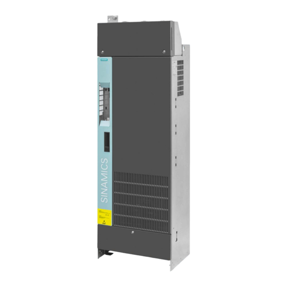
Introduction Power Module - PM330 The PM330 Power Module is a part of the modular family of SINAMICS G120 converters. PM330 Power Modules have been specifically optimized for driving pumps, fans, blowers and compressors with square-law load characteristic for use in HVAC applications. The Power Module is available with the "internal air cooling"... - Page 16 Introduction Figure 2-1 PM330 block diagram Power Module PM330 Hardware Installation Manual, 10/2016, A5E32844552B AD...
- Page 17 Introduction Note Principle of the precharging circuit SINAMICS PM330 Power Modules include a half-controlled thyristor bridge as rectifier circuit. As a result of the precharging principle with phase control, precharging is only started when all of the enable signals are available and by setting the ON/OFF command (p0840 = 1).
- Page 18 Introduction Power Module PM330 Hardware Installation Manual, 10/2016, A5E32844552B AD...
-
Page 19: Installing/Mounting
Installing/Mounting Installation conditions Unpacking and disposal Note The converter packaging can be reused. The individual components of the packaging can be recycled or disposed of in compliance with local regulations. General rules for protecting Power Modules against environmental effects To ensure that the Power Module is installed in the correct environmental conditions, please make sure that you adhere to the following guidelines: ●... -
Page 20: Power Losses And Air Cooling Requirements
Installing/Mounting 3.2 Power losses and air cooling requirements WARNING Danger to life due to voltage To ensure safe operation of the equipment, it must be installed and commissioned by qualified personnel in full compliance with the warnings laid down in this manual. It is especially important to comply with general and local installation and safety regulations for working on plants and systems with hazardous voltages (e.g. - Page 21 Installing/Mounting 3.2 Power losses and air cooling requirements Cooling requirements Depending on the power losses of the various components a specific cooling air flow is required to protect the components from overheating. The following equation shows you how to calculate the required air flow. 1.
-
Page 22: Mounting The Power Modules
Installing/Mounting 3.3 Mounting the Power Modules 7. Ensure that the electrical cabinet is adequately ventilated and is equipped with suitable air filters. It is crucial that you comply with the replacement intervals of the air filter (see also Chapter Service and maintenance (Page 57). The power losses and the required cooling airflow of the Power Modules are specified in Chapter Specific technical data (Page 70). - Page 23 Installing/Mounting 3.3 Mounting the Power Modules Note Fixing elements used The following fixing elements are used: • M8 screw • Washer according to DIN EN ISO 7093-1 and locking element Tightening torques: • electrical connections 50 Nm ±15 % (M12 bolts) •...
- Page 24 Installing/Mounting 3.3 Mounting the Power Modules Lifting Power Modules The Power Modules can be lifted using the lifting eyebolts provided. Use a lifting harness where the ropes or chains are maintained in a vertical position. The device must not be lifted at an angle because this can damage the housing.
-
Page 25: Chassis Units
Installing/Mounting 3.3 Mounting the Power Modules 3.3.1 Chassis units Drilling patterns, dimensions and clearances Figure 3-4 Dimension drawing of PM330 frame size GX, view from the side, view from the rear Power Module PM330 Hardware Installation Manual, 10/2016, A5E32844552B AD... - Page 26 Installing/Mounting 3.3 Mounting the Power Modules Figure 3-5 Dimension drawing of PM330 frame size HX, view from the side, view from the rear Power Module PM330 Hardware Installation Manual, 10/2016, A5E32844552B AD...
- Page 27 Installing/Mounting 3.3 Mounting the Power Modules Figure 3-6 Dimension drawing of PM330 frame size JX, view from the side, view from the rear Power Module PM330 Hardware Installation Manual, 10/2016, A5E32844552B AD...
-
Page 28: Control Unit Installation
Installing/Mounting 3.4 Control Unit installation Control Unit installation After opening the left-hand housing flap, the Control Unit is plugged onto the Power Module. To remove the Control Unit, press the blue release knob at the top of the Control Unit. Figure 3-7 Mounting and removing the Control Unit Note... -
Page 29: Connecting Up, Switching On
Connecting up, switching on Preconditions Line and motor connections can be established once the converter has been properly installed. It is crucial that the following notes are observed. DANGER Danger to life through electric shock due to the residual charge of the DC link capacitors Because of the DC link capacitors, a hazardous voltage is present for up to five minutes after the power supply has been switched off. -
Page 30: Cable Lugs
Connecting up, switching on 4.1 Cable lugs Cable lugs Cable lugs The cable connections on the devices are designed for cable lugs according to DIN 46234 or DIN 46235. For connection of alternative cable lugs, the maximum dimensions are listed in the table below. -
Page 31: Line, Motor And Dc Link Connection
Connecting up, switching on 4.2 Line, motor and DC link connection Line, motor and DC link connection Arrangement of the converter terminals, see Access to power and motor terminals (Page 34). For all connections, carefully observe EMC regulations, see EMC compliant connection (Page 49). -
Page 32: Line Connection
Connecting up, switching on 4.2 Line, motor and DC link connection Additional requirements placed on the protective conductor of the line feeder cable: ● For permanent connections, the protective conductor must fulfill at least one of the following conditions: – The protective conductor is routed so that it is protected against damage along its complete length. -
Page 33: Motor Connection
150 m du/dt filter compact 4.2.4 Motor connection Star and delta connection Siemens motors have a diagram inside the terminal box showing both connection methods: • Star connection (Y) • Delta connection (Δ) The motor rating plate provides data about the correct connection. -
Page 34: Access To Power And Motor Terminals
Connecting up, switching on 4.2 Line, motor and DC link connection 4.2.5 Access to power and motor terminals Access to line and motor terminals The line and motor terminals are accessible via the following steps: 1. Release the 2 screws from the cover of the line connection terminals and remove the cover towards the... - Page 35 Connecting up, switching on 4.2 Line, motor and DC link connection Line and motor terminals Frame sizes GX, HX The diagram shows the layout of line and motor terminals and terminal strip X9. Optionally, the line connection can be established using the "Installation set for line-side cable connection, left", see In- stallation set for line-side cable...
- Page 36 Connecting up, switching on 4.2 Line, motor and DC link connection Frame size JX The diagram shows the layout of line and motor terminals and terminal strip For frame size JX, only connection from the top or bottom is possible. Tightening torques for the line, motor and PE termi- nals (M12): 50 Nm...
- Page 37 Connecting up, switching on 4.2 Line, motor and DC link connection WARNING Danger to life as a result of electric shock when the line feeder cable installation is damaged If the line feeder cables are incorrectly routed, the insulation can be damaged when coming in contact with the sharp edges of the PE connecting lugs - which can result in a short- circuit.
-
Page 38: Dc Link Connection
Connecting up, switching on 4.2 Line, motor and DC link connection 4.2.6 DC link connection Connecting an external Braking Module PM330 Power Modules permit an external Braking Module to be connected via the DCP and DCN DC link connecting terminals. Characteristic data of the connecting terminals (@ U 380 V –... -
Page 39: Operation On A Non-Grounded Line Supply (It System)
Connecting up, switching on 4.3 Operation on a non-grounded line supply (IT system) Operation on a non-grounded line supply (IT system) If the built-in unit is operated from a non-grounded supply (IT system), the connection to the basic interference suppression module of the Power Module must be opened. NOTICE Damage to the device through not removing the connection clip with a non-grounded line supply... - Page 40 Connecting up, switching on 4.3 Operation on a non-grounded line supply (IT system) Figure 4-4 Open the connection to the interference suppression module The connection is opened as follows: ① 1. Release the left-hand housing flap by rotating latch and opening the housing flap. ②...
-
Page 41: Installation Set For Line-Side Cable Connection, Left
Connecting up, switching on 4.4 Installation set for line-side cable connection, left Installation set for line-side cable connection, left Description Alternatively, for devices, frame sizes GX and HX, the line connection can be established using the "Installation kit for line-side cable connection, left". This means that it is possible to mount the Power Module at the top of the control cabinet without any clearance. - Page 42 Connecting up, switching on 4.4 Installation set for line-side cable connection, left ② 2. Mount the installation set , tightening torque: 50 Nm Figure 4-6 Installing the mounting kit, step 2 Power Module PM330 Hardware Installation Manual, 10/2016, A5E32844552B AD...
- Page 43 Connecting up, switching on 4.4 Installation set for line-side cable connection, left ③ 3. Final state with mounted installation set, tightening torque for the fixing screws : 50 Nm Figure 4-7 Installing the mounting kit, step 3 ④ 4. The cable entry protection must be broken out corresponding to the diameter of the cable to be introduced.
- Page 44 Connecting up, switching on 4.4 Installation set for line-side cable connection, left Installing the "Mounting kit for line-side cable connection, left" 6SL3366-1LH00-0PA0 for frame size HX The mounting kit is installed in 4 steps: 1. Remove the busbar adapter for the cable outlet towards the top and the adapter for the ①...
- Page 45 Connecting up, switching on 4.4 Installation set for line-side cable connection, left ② 2. Mount the installation set for connections U1, V1, W1 , tightening torque: 50 Nm and ③ the installation set , tightening torque: 6 Nm. ④ Tightening torque for screw : 3 Nm Figure 4-10 Installing the mounting kit, step 2...
- Page 46 Connecting up, switching on 4.4 Installation set for line-side cable connection, left ⑤ 3. Final state with mounted installation set, tightening torque for the fixing screws : 50 Nm Figure 4-11 Installing the mounting kit, step 3 ⑥ 4. The cable entry protection must be broken out corresponding to the diameter of the cable to be introduced.
-
Page 47: Terminal X9
Connecting up, switching on 4.5 Terminal X9 Terminal X9 Terminal strip X9 is used to connect an external 24 VDC power supply and to connect a main or bypass contactor. Fault and alarm signals can be connected to the digital inputs. The digital output allows, for example, an external rectifier to be controlled. - Page 48 Connecting up, switching on 4.5 Terminal X9 Terminal Name Meaning Input/ Technical data output Not connected Activation line Activation main contactor Output Contact type: NO contact contactor Maximum load current: 4 A, 230 VAC, cosφ = 0.6 ind Floating Activation line Activation main contactor Output contactor A device to protect against overload and short-circuit is...
-
Page 49: Emc Compliant Connection
Connecting up, switching on 4.6 EMC compliant connection EMC compliant connection 4.6.1 Avoiding electromagnetic interference Figure 4-13 EMC measures Installation in conformance with EMC requirements is only possible using simultaneous filtering, grounding and shielding. The most important installation rules for converter and drive systems are described in the following sections. -
Page 50: Cabinet Design
Connecting up, switching on 4.6 EMC compliant connection Care must be taken to prevent any potential differences regarding the ground potential between the zones. These must be avoided to protect the cable shields from excessively high equalizing currents. • Zone A: Line connection Limit values for conducted interference emissions and... -
Page 51: Cabling
Connecting up, switching on 4.6 EMC compliant connection The most favorable design is to mount these devices and supplementary components on a bare metal mounting plate with good conducting characteristics; this in turn is connected to the control cabinet frame through a good electrical connection and the largest possible surface area. - Page 52 Connecting up, switching on 4.6 EMC compliant connection ● The shields of the signal cables at the Control Unit must be connected at the Power Module below the mounted Control Unit using the shield connecting terminals provided at the slits available for the purpose. The cables are mechanically fixed (strain relief) using cable ties, also below the mounted Control Unit at the locations provided below the slits used for mounting.
-
Page 53: Equipotential Bonding
Connecting up, switching on 4.6 EMC compliant connection 4.6.5 Equipotential bonding Equipotential bonding ● Equipotential bonding within a cabinet element has to be established by means of a suitable mounting plate (back plane), to which all metallic housings of the devices and additional components integrated in the cabinet element (e. - Page 54 Connecting up, switching on 4.6 EMC compliant connection Therefore, connect the protective ground conductor and the cable shield to the motor and to the converter. Figure 4-14 Grounding and high-frequency equipotential bonding measures in the drive system and in the plant Power Module PM330 Hardware Installation Manual, 10/2016, A5E32844552B AD...
- Page 55 Connecting up, switching on 4.6 EMC compliant connection Additional measures Finely stranded, braided copper cables have to be routed in parallel with the cable shields in the following cases: ● Old installations with existing unscreened cables ● Cables with poor high-frequency properties of the shield ●...
-
Page 56: Switching On
Connecting up, switching on 4.7 Switching on Switching on The converter is switched on in the following steps: ● Switch on the line voltage – The power supply inside the converter switches on, – the DC link is still not precharged. ●... -
Page 57: Service And Maintenance
Defective parts must be replaced immediately. Note The actual maintenance intervals depend on the installation and operating conditions. Siemens offers its customers support in the form of service contracts. For further information, contact your Siemens regional office or sales office. Power Module PM330... - Page 58 Service and maintenance 5.1 Maintenance Safety instructions for maintenance and repair work WARNING Danger to life if the fundamental safety instructions and remaining risks are not carefully observed The non-observance of the fundamental safety instructions and residual risks stated in Chapter Basic safety instructions (Page 7) can result in accidents with severe injuries or death.
-
Page 59: Forming
Service and maintenance 5.2 Forming Forming Forming the DC link capacitors If converters were not operational for longer than a year (if possible: storage temperature < 40 °C), the DC link capacitors should be formed. The date of manufacture and therefore the storage time can be determined based on the Power Module serial number. - Page 60 Service and maintenance 5.2 Forming Code to encrypt the date of manufacture The date of manufacture is encrypted in positions 3 - 6 of the serial number. Figure 5-2 Code to encrypt the date of manufacture In this example, the date of manufacture is April 21, 2013 Power Module PM330 Hardware Installation Manual, 10/2016, A5E32844552B AD...
-
Page 61: Replacing The Cooling Fan
Service and maintenance 5.3 Replacing the cooling fan Replacing the cooling fan 5.3.1 Service life of the cooling fan Service life of the fan The average service life of the fan is 50,000 hours. In practice, however, the service life may deviate from this value. - Page 62 Service and maintenance 5.3 Replacing the cooling fan Figure 5-3 Fan removal for frame size GX, view from below Installation For re-installation, carry out the above steps in reverse order. Tightening torque for the captive fixing screws: 1.8 Nm. Power Module PM330 Hardware Installation Manual, 10/2016, A5E32844552B AD...
-
Page 63: Fan Replacement For Hx, Jx
Service and maintenance 5.3 Replacing the cooling fan 5.3.3 Fan replacement for HX, JX Fan replacement for frame sizes HX and JX Removal 1. Switch the converter off. ① 2. Remove the fixing screws from the left fan ( ). The screws are captive. 3. - Page 64 Service and maintenance 5.3 Replacing the cooling fan Figure 5-4 Fan removal for frame size HX, view from below (view is similar to frame size JX) Installation For re-installation, carry out the above steps in reverse order. Tightening torque for the captive fixing screws: 1.8 Nm Power Module PM330 Hardware Installation Manual, 10/2016, A5E32844552B AD...
-
Page 65: Technical Specifications
Technical specifications Converters for installation in the US (UL) and in Canada (cUL) Use cUL- approved 3NE1 or 3NB3 fuses to ensure that the system is in conformance with cULus. Only use copper conductors approved for 75°C. Input and output terminals must be connected using UL-approved ring cable lugs (UL Category ZMVV) for min. -
Page 66: General Technical Data
Technical specifications 6.1 General technical data General technical data Table 6- 1 General technical data Electrical data Line system configurations Grounded TN/TT systems or ungrounded IT systems (a grounded phase conductor is not permissible in 690 V line supplies) Line requirement A line reactor (2% u ) must be connected in series Line voltage... - Page 67 Technical specifications 6.1 General technical data Ambient conditions During storage During transport During operation Ambient temperature -25° … +55° C -25 ... +70 °C 0° ... +40° C –40 °C from for 24 hours up to + 50° C with derating 5 to 95% Relative humidity 5 ...
- Page 68 Technical specifications 6.1 General technical data Operating ranges The converter can only be operated with reduced output current at low output frequencies. The connection is shown in the following diagram. The diagram clearly demarcates continuous duty ranges from short-time duty ranges. The operating ranges are used to ensure that the converter operates reliably at all times, including in particular in relation to lifetime expectancy.
- Page 69 Technical specifications 6.1 General technical data Permissible inverter overload The inverters have different load capabilities, "High Overload" and "Low Overload", depending on the expected. Figure 6-2 Load cycles, Low Overload" and "High Overload" Note Please note the base load (100 % power or current) for Low Overload is higher than the base load for High Overload.
-
Page 70: Specific Technical Data
Technical specifications 6.2 Specific technical data Specific technical data Note Recommended connection cross-sections The recommended connection cross-sections are determined for copper cables at 40° C (104° F) ambient temperature and cables with a permitted operating temperature at the conductor of 70° C (installation type C - factor for bundling 0.75 considered) according to DIN VDE 0298-4/08.03). - Page 71 Fuse according to IEC 3NE1333-2 3NE1334-2 3NE1435-2 (450 A/690 V) (500 A/690 V) (560 A/690 V) Manufacturer: Siemens AG Siemens AG Siemens AG Maximum permissible line short-circuit current I ≤ 100 kA ≤ 100 kA ≤ 100 kA kmax Minimum line short-circuit current required I >...
- Page 72 Technical specifications 6.2 Specific technical data Article no. 6SL3310- 1PE33-0AA0 1PE33-7AA0 1PE34-6AA0 Tightening torque for line, motor, DC link, and 50 Nm / 443 lbf in 50 Nm / 443 lbf in 50 Nm / 443 lbf in ground cable Dimensions: Width x height x depth (mm) 452 x 1447 x 327.5 452 x 1447 x 327.5...
- Page 73 Fuse according to IEC 3NE1437-2 3NE1438-2 3NE1448-2 (710 A/690 V) (800 A/690 V) (850 A/690 V) Manufacturer: Siemens AG Siemens AG Siemens AG Maximum permissible line short-circuit current I ≤ 100 kA ≤ 100 kA ≤ 100 kA kmax Minimum line short-circuit current required I >...
- Page 74 Technical specifications 6.2 Specific technical data Article no. 6SL3310- 1PE35-8AA0 1PE36-6AA0 1PE37-4AA0 Tightening torque for line, motor, DC link, and 50 Nm / 443 lbf in 50 Nm / 443 lbf in 50 Nm / 443 lbf in ground cable Dimensions: Width x height x depth (mm) 548 x 1695 x 393 548 x 1695 x 393...
- Page 75 2 x 3NE1436-2 // (2 x 500 A / 690 V) (2 x 560 A / 690 V) (2 x 630 A / 690 V) Manufacturer: Siemens AG Siemens AG Siemens AG Maximum permissible line short-circuit current I ≤ 100 kA ≤...
- Page 76 Technical specifications 6.2 Specific technical data Article no. 6SL3310- 1PE38-4AA0 1PE38-8AA0 1PE41-0AA0 Recommended cable cross-section for 480 V - DC link infeed (2/3 converter power) 3 x 120 mm 3 x 150 mm 3 x 185 mm - Braking Module 35 mm²...
- Page 77 Fuse according to IEC 3NE1333-2 3NE1334-2 3NE1435-2 (450 A/690 V) (500 A/690 V) (560 A/690 V) Manufacturer: Siemens AG Siemens AG Siemens AG Maximum permissible line short-circuit current I ≤ 100 kA ≤ 100 kA ≤ 100 kA kmax Minimum line short-circuit current required I >...
- Page 78 Technical specifications 6.2 Specific technical data Article No. 6SL3310- 1PG33-7AA0 1PG34-0AA0 1PG34-5AA0 Recommended cable cross-section for 500 V - DC link infeed (2/3 converter power) 2 x 95 mm 2 x 120 mm 2 x 150 mm Recommended cable cross-section for 690 V - DC link infeed (2/3 converter power) 2 x 95 mm 2 x 120 mm...
- Page 79 HO base load output current at 690 V 394 A Fuse according to IEC 3NE1436-2 (630 A/690 V) Manufacturer: Siemens AG Maximum permissible line short-circuit current I ≤ 100 kA kmax Minimum line short-circuit current required I > 8.5 kA...
- Page 80 Technical specifications 6.2 Specific technical data Article No. 6SL3310- 1PG35-2AA0 Recommended cable cross-section for 500 V - DC link infeed (2/3 converter power) 2 x 150 mm Recommended cable cross-section for 690 V - DC link infeed (2/3 converter power) 2 x 150 mm Tightening torque for line, motor, DC link, and 50 Nm / 443 lbf in...
- Page 81 Fuse according to IEC 3NE1437-2 3NE1438-2 3NE1448-2 (710 A/690 V) (800 A/690 V) (850 A/690 V) Manufacturer: Siemens AG Siemens AG Siemens AG Maximum permissible line short-circuit current I ≤ 100 kA ≤ 100 kA ≤ 100 kA kmax Minimum line short-circuit current required I >...
-
Page 82: Derating Data
Technical specifications 6.3 Derating data Article No. 6SL3310- 1PG35-8AA0 1PG36-5AA0 1PG37-2AA0 Recommended cable cross-section for 500 V - line cable 2 x 240 mm 3 x 185 mm 3 x 185 mm - motor cable 2 x 185 mm² 2 x 240 mm² 2 x 240 mm²... -
Page 83: Derating As A Function Of The Installation Altitude
Technical specifications 6.3 Derating data 6.3.2 Derating as a function of the installation altitude Voltage The insulation clearances within the converter are measured for surge voltages in accordance with overvoltage category III in compliance with EN 60664-1 for installation altitudes up to 2000 m above sea level. Use of an isolating transformer to reduce transient overvoltages to IEC 61800--5--1 By using the isolating transformer, overvoltage category III is reduced to overvoltage category II. -
Page 84: Derating Factor Of The Output Current As A Function Of The Line Voltage
Technical specifications 6.3 Derating data Current Figure 6-4 Derating of the output current in accordance with the installation altitude with frame size GX Figure 6-5 Derating of the output current as a function of the installation altitudes for frame sizes HX and JX 6.3.3 Derating factor of the output current as a function of the line voltage... -
Page 85: Derating Of The Output Current As A Function Of The Pulse Frequency
Technical specifications 6.3 Derating data Table 6- 9 Derating of the output current as a function of the line voltage, 3 AC 500 V … 690 V Power Module Rated output current I 500 V 575 V 600 V 660 V 690 V 500 V/690 V 6SL3310-1PG33-7AA0 368 A / 340 A... - Page 86 Technical specifications 6.3 Derating data Power Module PM330 Hardware Installation Manual, 10/2016, A5E32844552B AD...
-
Page 87: Appendix
Appendix Further information on your converter A.1.1 Manuals for your inverter Table A- 1 Manuals for your converter Depth of Manual Contents Languages Download or article number the infor- mation Getting Started Installing the converter and German, Download manuals Control Units CU230P-2; commissioning. -
Page 88: Configuring Support
SINAMICS German (www.siemens.com/sinamics-g120) G converters Online catalog (Indus- Ordering data and technical infor- English, try Mall) mation for all SIEMENS products German SIZER The overall configuration tool for English, You obtain SIZER on a DVD SINAMICS, MICROMASTER and German,... -
Page 89: Certificates
A.1.4 Certificates Downloading certificates You can find the certificates in the Internet here: Certificates (https://support.industry.siemens.com/cs/ww/en/ps/13218/cert). Electromagnetic compatibility The SINAMICS G120 drives have been tested in accordance with the EMC product standard EN 61800-3:2004. For precise data, refer to the declaration conformity A.2.1... -
Page 90: Compliance With Emc Environment And Categories
Appendix A.2 Electromagnetic compatibility Categories Category C1 Power Drive System (PDS) of rated voltage less than 1000 V intended for use in the First (Domestic) Environment. Category C2 Power Drive System (PDS) of rated voltage less than 1000 V, which is neither a plug-in device nor a movable device, and when used in the First Environment, is only intended to be installed and commissioned by a professional. - Page 91 Appendix A.2 Electromagnetic compatibility Category C2 – First environment - commercial use Power Modules with additional line filter ● fulfill the requirements relating to cable-conducted noise interference emission (interference), if – a shielded cable with low capacitance is used, – the current does not exceed the rated input current (see Specific technical data (Page 70)), –...
-
Page 92: Emc Limit Values In South Korea
Appendix A.3 Abbreviations Harmonic currents Table A- 3 Typical harmonic currents of a 6-pulse rectifier with line reactor u = 2 % Typical harmonic current (% of rated input current) with line reactor u Line supply with average, relative short-circuit power (RSC = 50), u = 2 %, with line reactor u = 2 % THD(I) -
Page 93: Abbreviations
Appendix A.3 Abbreviations Abbreviations Abbreviation State Alternating current Communauté Européenne Control Unit DC current Digital input DIP switch Digital output Equivalent circuit diagram European Community ELCB Earth leakage circuit breaker Electromagnetic compatibility (EMC) Electromagnetic interference Electrostatic discharge FS… Frame size ... Getting Started High overload Input/output... - Page 94 Appendix A.3 Abbreviations Power Module PM330 Hardware Installation Manual, 10/2016, A5E32844552B AD...
-
Page 95: Index
Index Catalog, 88 Industry Mall, 88 Category C1, 90 Installation altitude, 83 Category C2, 90 IP20 degree of protection, 19 Category C3, 90 IT system, 39 Classification of EMC behavior, 89 Configuring support, 88 Cooling, 21 cUL-compliant installation, 65 List Manual, 87 Derating, 85 Maintenance Installation altitude, 83... - Page 96 Index Questions, 88 Removing the CU, 28 Residual risks of drive systems, 13 Safety instructions Electromagnetic fields, 11 Electrostatically Sensitive Devices, 11 General safety instructions, 7 Safety notes Electrical installation, 29 Second environment, 89 Service life of the fan, 61 SIZER, 88 Standards EN 61800-3, 89...
Need help?
Do you have a question about the SINAMICS G120P PM330 and is the answer not in the manual?
Questions and answers