Table of Contents
Advertisement
Quick Links
Advertisement
Table of Contents

Subscribe to Our Youtube Channel
Summary of Contents for Delphin Expert Logger
- Page 2 Copyright © 2003-2018 Delphin Technology AG. All rights reserved. This document's content, especially text, images, and graphics are pro- tected by copyright. When not otherwise stated, the copyright belongs to Delphin Technology AG, Lustheide 81, in 51427 Bergisch Gladbach, Ger- many. All the trademarks and brands used in this manual refer only to the respect- ive product or trademark holder. Delphin Technology claims no rights other than those to its own trademarks and brands. Expert Logger Manual Delphin Technology AG Januar 2018...
-
Page 3: Table Of Contents
Expert Logger Contents 1 Introduction 1.1 Safety advice 1.2 System requirements 1.3 Symbols used 1.4 Included in delivery: 2 Getting started 2.1 Installing the programs 2.2 PC connection 2.3 Starting the device 2.4 Basic settings 3 Expert Logger displays and connections 3.1 Power supply 3.2 Display, LEDs 3.3 COM interfaces, CAN bus 3.4 Sensor connection (sensor terminals) 4 Configuration and operation 4.1 Overview 4.2 Configuring the network via the display 4.3 Configuring and operating the display 4.4 Configuration via an Internet browser 4.4.1 Configuration 4.4.1.1 Channels overview (Show configuration table) 4.4.1.2 View current values (live channel values) 4.4.1.3 Resetting configuration 4.4.2 Service 4.4.2.1 System report 4.4.2.2 PROFIBUS GSD file... - Page 4 4.10.1 Analogue inputs (Expert Logger) 4.10.1.1 Voltage sensor type 4.10.1.2 Sensor type current 0/4 mA to 20 mA 4.10.1.3 Resistance sensor type 4.10.1.4 Resistance thermometer sensor type 4.10.1.5 Thermocouple sensor type 4.10.1.6 Ph probe sensor type 4.10.1.7 Measuring bridge sensor type 4.10.2 Configuring digital inputs 4.10.2.1 Counter (hardware) 4.10.2.2 Frequency 4.10.3 Digital / PWM outputs (Expert Logger) 4.11 Configuring software channels 4.11.1 Adder 4.11.2 Operating hours counter 4.11.3 Differentiator 4.11.4 Event (Mail) 4.11.5 Flip-flop 4.11.6 Limit value 4.11.7 Pulse generator 4.11.8 Integrator 4.11.9 Channel group 4.11.10 Linearisation 4.11.11 Logic 4.11.12 Variable 4.11.13 Average 4.11.14 PID controller 4.11.14.1 Introduction to control technology 4.11.14.2 Controller parameter settings 4.11.14.3 Configuring PID controllers 4.11.15 Pulse width modulation (PWM) 4.11.16 Calculation channel Expert Logger Manual Delphin Technology AG Januar 2018...
- Page 5 4.12.2.1 Modbus Device (Server) 4.12.2.2 Modbus Device (Client) 4.12.2.3 Modbus channel 4.12.3 CAN connection 4.12.3.1 CAN protocol 4.12.3.2 CAN bus channel 4.12.4 COM connection 4.12.4.1 PROFIBUS protocol 4.12.4.2 PROFIBUS channel 4.12.4.3 PROFIBUS logger protocol 4.12.4.4 PROFIBUS logger pair 4.12.4.5 Modbus RTU Slave/Master 4.12.4.6 User-defined protocol 4.12.5 LAN 4.12.6 USB device 4.12.7 USB device (host, such as memory) 4.12.8 WLAN (option) 4.12.9 WWAN (option) 4.12.10 OpenVPN 4.13 Device memory 4.13.1 Main settings tab 4.13.2 External memory backup tab 4.13.3 Channel list tab 5 Connection examples 5.1 Connecting sensors 5.2 Connecting actuators 6 Measurement technology notes Expert Logger Manual Delphin Technology AG Januar 2018...
- Page 6 Expert Logger 6.1 Galvanic isolation 6.2 Earthing 6.3 Earth loops 6.4 Shielding 6.5 ESD protection 6.6 Potential differences 7 Technical specifications Expert Logger 100, 200, 300, 400 8 Appendix 8.1 ISO 9001 certificate 8.2 EC declaration on conformity Expert Logger Manual Delphin Technology AG Januar 2018...
-
Page 7: Introduction
series. With this device you have acquired a high quality product with extensive options for data acquisition and processing. This manual is included in the delivery. Always keep the manual available for reference. To avoid any damage occurring to yourself or your equip- ment, carefully follow the guidance and safety precautions given in this manual. If your equipment has a problem that this manual does not address, please contact us. This manual is intended for technicians and engineers or similarly qualified persons wishing to use the device. If you find errors in the product or in this documentation, or if you have any suggestions for its improvement, we welcome your feedback. Contact: Delphin Technology AG Lustheide 81 51427 Bergisch Gladbach (Refrath), Germany Phone: (+49-2204) 97685-0 Fax: (+49-2204) 97685-85 info@delphin.de E-mail: www.delphin.de Contact USA: Delphin Technology AG 4860 Cox Road, Suite 2000 Glen Allen, VA 23660 Virginia, United States Phone: (+1-804) 217-8391 Fax: (+1-804) 747-6182 info@delphin.de E-mail: www.delphin.com Expert Logger Manual Delphin Technology AG Januar 2018... -
Page 8: Safety Advice
See also Potential differences. See also "Potential differences" on page 265. Installing modules, memory card or battery Electronic components are sensitive to ESD ( lectro- tatic ischarge). Therefore, discharge any electrostatic energy before opening the device, for example to install an I/O module or to replace the integrated memory card. We recommend wearing an anti-static wrist band (static discharge wrist band) and to carry out the work on a conductive surface. ESD damage can have a number of effects, from deviation in individual specifications to total device failure. Expert Logger Manual Delphin Technology AG Januar 2018... -
Page 9: System Requirements
To make reading this manual easier for you, we use the following symbols: WARNING! This symbol warns of a potential hazard which - if the safety requirements are not followed - may be fatal or cause serious physical injury. Indicates important inform- ation. Expert Logger Manual Delphin Technology AG Januar 2018... -
Page 10: Included In Delivery
. User inputs are in most cases illustrated with examples and highlighted in yel- 192.168.251.252 low: Use as the IP address. We hope that this helps you to more quickly identify the corresponding fields, buttons, and menus, and to locate these in the program. Device labelling CE symbol: The CE symbol guarantees that our products meet the require- ments of relevant EU directives. 1.4 Included in delivery: Included in delivery: Expert Logger device Connecting plugs for inputs and outputs and power supply Brackets for rail mountings Ethernet crossover cable DVD of the software ProfiSignal Quick Start Guide Screwdriver Expert Logger Manual Delphin Technology AG Januar 2018... -
Page 11: Getting Started
See also Configuration and operation. The Section on Examples of connections shows the options for connecting standard sensors and actuators and how to configure them. The Section on Measurement technology notescontains general information and recommendations on applying measurement technology. Technical data is available in the Section on Technical specifications. 2.1 Installing the programs You need administrator rights to install the pro- gram. ProfiSignal Install the DVD . During the installation, ensure that you DataService Configurator install the as a program (and not as a service). After default installation you will find both of these symbols on your desktop: Expert Logger Manual Delphin Technology AG Januar 2018... -
Page 12: Pc Connection
LAN connection See also , Info As an alternative to the procedure described here, you can set the IP address and subnet mask used also via the E xpert Logger device’s display, see Network configuration via the display. Preparing the device to PC connection Connect your PC and the device using the Ethernet crossover cable supplied. Alternatively you can connect the device and PC also via a network hub or switch. Establish device connection 1. Start the DataService Configurator program, to create the connection and make the configuration. The DataService starts and the Connections tab is displayed on the left- hand side in the DataService Configurator. 2. Via the menu item Connect→ Find Delphin device on LAN. Also, as shown in the image, you can use the Add driver (connection) context menu in the Expert Logger Manual Delphin Technology AG Januar 2018... - Page 13 Expert Logger DataService entry on the left of the window. 3. The device search takes place and a dialogue with the found device(s) is displayed. 4. In the Add column, enable the device or devices that you want to connect to. Then click Add. If the device IP address does not correspond with that of your PC, you must first assign a different network address. If no devices are found, for example, if the scan required for searching (port 16555) is not permitted in the network, you can either try a direct connection with your PC (with no network) or the method described below for direct connection with PC and fixed address. 5. If the device’s User management is enabled, another dialogue opens. Here, under username and password, enter your login data. The successful connection is then displayed with IP address and status. Expert Logger Manual Delphin Technology AG Januar 2018...
- Page 14 6. PC. Set different network address If the device IP address does not correspond with that of your PC, after a device search you will be able to change the address, before you connect to the device: Enter a suitable IP address corresponding to your PC IP address (similar root but not the same) and subnet mask. For a new device, use the user, User username and password are then only relevant if you have enabled management on the device. Enter the required data and click . The set- tings are saved and you will need to carry out a new search (click on Update Alternatively you can also change the IP address using the touch display: click on Network and then on the number to be changed. Using the keys above or below the numbers, you can increase or decrease the displayed numbers. A third option is configuration via any Internet browser: 1. Launch your Internet browser and in the address bar enter http:// and the current device address, for example http://192.168.251.252. The device connection is established and the home page is shown. 2. In the Settings section, click on Network. The page with the network settings is displayed. Expert Logger Manual Delphin Technology AG Januar 2018...
- Page 15 Direct connection with PC and fixed address If your network does not allow scanning (port 16555 not enabled), then the DataService Configurator cannot find the device. In this case you will need to establish a direct connection between the PC and device, and set the PC to the device address range in order to be able to make a connection. While you have a connection, you can set your device address to one that is suitable for your network, as described above. Ports 80 (connection via web browser) and/or 1033 (connection via DataService Configurator) must be enabled for the TCP protocol. Delphin The device IP address is identified at the factory with a sticker. If the sticker has been lost during transport and can no longer be found, please search for it using IP address 192.168.251.252 (net mask: 255.255.240.0). (Temporarily) set your PC to a different address in the same IP segment: 1. Open the dialogue for your network connections. 2. Depending on the operating system, open the dialogue either via the Win- dows Start button and Network settings or via the Control Panel andNet- work and Sharing Center. 3. Display the connection (interface) Properties via which you want to con- nect the device (normally called LAN connection). In Windows Vista and in Windows 7, click on Show status, and then on Properties. Expert Logger Manual Delphin Technology AG Januar 2018...
- Page 16 Expert Logger 4. Display the Internet protocol Properties. 5. In the following dialogue you can either enter a fixed address for your PC or, if the PC is set to DHCP and to be used in the LAN, use the option of spe- cifying an alternative configuration for cases where the network (server) Expert Logger Manual Delphin Technology AG Januar 2018...
- Page 17 Expert Logger is unavailable (recommended procedure). 6. Enter an address that is within the same segment as the device address (see above figure for an example). Also set the subnet mask. 7. Close the dialogue with OK. Then try again to make a connection with the device. However, please use the Connect→ Add Delphin device menu to do this, and enter your device type. Expert Logger Manual Delphin Technology AG Januar 2018...
- Page 18 Expert Logger 8. Enter the IP address of the device in the dialogue, for example, 192.168.251.252. 9. If the device’s User management is enabled, enter your login data under Username and Password. 10. For time signals and spectra, you have the option to compress acquired measurement values. Compression reduces memory requirements sig- nificantly and comes with losses. Note: Compression can cause the min/max characteristic values to not exactly match the time signal or spectrum. 11. Click OK to create the connection. 12. While you have a connection, set your device address to an IP address that is suitable for your network, as described above. However do not forget to reset your PC to the original address. Offline configuration → Configuration If you want to work with a saved offline, select Connect Add Delphin device and your device type. Expert Logger Manual Delphin Technology AG Januar 2018...
-
Page 19: Starting The Device
and enter the path and filename, or click on Select , to search for the file. The configuration file is loaded and the device contained in it is shown in the channel tree as a physically available device. All changes you make to the configuration are saved dir- ectly in the configuration file. To connect via XML, you must enable port 1035 for TCP (XiMP), and to connect via Web socket you must enable port 1036 for TCP (WiMP). Refer also to Main settings: services. 2.3 Starting the device Just a few steps are required to start using your new d evice: Expert Logger Manual Delphin Technology AG Januar 2018... -
Page 20: Basic Settings
Basic settings 2.4 Basic settings The DataService Configurator dialogue is split, enabling a device to be Connections selected on the left in the tab and settings to be applied on Channels the right in the tab. Displaying measurement data connection to the device Once you have established a , you can see the current measured values: double-click your device on the right, then on I/O Channels to open the entry and display all available channels or chan- nel groups. If required, click on one of the groups and the on input or out- Value put, to view the sub-entry or sub-entries. The column continuously updates with new measurement data. Displaying scaled measurement data To convert data from the sensor into the required measurement unit requires configuration of the channel. This allows the sensor measurement Expert Logger Manual Delphin Technology AG Januar 2018... - Page 21 ProfiMessage D Configuring I/O module channels under . The dia- I/O module connection log also displays connection diagrams. Under terminal blocks , you will find the terminal assignments for the I/O mod- LogMessage ProfiMessage ProfiMessage D ules of , or Other settings Define digital I/O Scaling can also be made for counter inputs. Set which signal (channel) requires output of a constant level. Set device-specific settings Options are available for system monitoring, e.g. CPU utilization or the avail- able memory, and interface configurations. Create computed channels (dependent channels) Your Delphin device has many options for further processing data before the data is saved or output. The corresponding settings are described in con- figuring software channels. Expert Logger Manual Delphin Technology AG Januar 2018...
-
Page 22: Expert Logger Displays And Connections
Expert Logger Expert Logger displays and connections Displays and connections are described in the following Sections: Power supply Display and LEDs COM interfaces and CAN bus 3.1 Power supply Input voltage: 12 VDC – 24 VDC ±10% Pmax power input: 10 W Pin assignment Label Description Earthing Protective Earth, refer to Middle Neutral Bottom Power supply Expert Logger Manual Delphin Technology AG Januar 2018... -
Page 23: Display, Leds
Configure the LED display access to the memory (LED 2) by default. in System → DataService Configurator via LEDs LAN2 (PC interface) Status Description Link Left blinking Data transfer 1 x blinking 10 Mbit Right 2 x blinking 100 Mbit 3 x blinking 1 GB 3.3 COM interfaces, CAN bus COM1/2 and CAN1/2 Expert Logger Manual Delphin Technology AG Januar 2018... - Page 24 Supply voltage/Plus (5 V) — CANH — CAN bus high RxD/TxD- Receive/transmit data-Minus — (RS-485) — Not connected No galvanic isolation between CAN1 and COM1 or CAN2 and COM2. CANHL/CANH have an integrated terminating resistor of 120 Ω. COM3 Pin assignment 9-pole Sub-D plug Description COM3 DIN 41 652, Part 1 Signal (ISO 4902) Earthing Housing Shield Shield / protective ground, refer to Received signal level, Data Carrier Detect (RS-232) Receive Data (RS-232) Expert Logger Manual Delphin Technology AG Januar 2018...
-
Page 25: Sensor Connection (Sensor Terminals)
Description COM3 DIN 41 652, Part 1 Signal (ISO 4902) Transmit Data (RS-232) Data Terminal Ready (RS-232) Signal Ground — Not connected Request to Send (RS-232) Clear to Send (RS-232) — Not connected 3.4 Sensor connection (sensor terminals) Expert Logger Sensor terminals 100 Expert Logger Sensor terminals 200 Expert Logger Manual Delphin Technology AG Januar 2018... - Page 26 Expert Logger Expert Logger Sensor terminals 300 Expert Logger Manual Delphin Technology AG Januar 2018...
-
Page 27: Configuration And Operation
The Configuring software channels section describes the various ways in which to perform calculations on measurement data or between channels. Read the Configuring interfaces section on how to use the various interfaces for connecting or exchanging data with external devices. Devices are equipped with internal memories to enable measurement data to be saved. The Device memory Section explains how this storage space can be used, for example for partitioning of different channel groups. The Data transfer to USB memory stick Section explains how to externally back up internally stored data. Settings for all dialogues See also Getting Started and 4.1 Overview See also Getting Started Configuration of the most important parameters, such as network settings, can be performed using either the Web Interface from the device or the DataService Configurator program. Settings via the Web interface are Configuration via Web browser described in the Section. A detailed description of the program DataService Configurator is available in the manual on DataService Configurator. A detailed description of the pro- DataService gram DataService Configurator is available in the manual on Configurator. ClickingDataService Configurator starts the DataService background pro- gram and establishes a connection to the devices (the default for the first Expert Logger Manual Delphin Technology AG Januar 2018... - Page 28 Channels from a channel group are displayed by clicking the cor- responding plus sign ( ) before the group. DataService Configurator options Hide or show columns for the different tabs on or off: View→ Left panel → Visible columns... or View→ Right panel → Visible columns... Set the DataService Configurator time zone: View → Timezone. Change the DataService Configurator's display language via Options → Lan- guage. Suppress confirmation requests: Options→ Don't prompt for confirmation. Expert Logger Manual Delphin Technology AG Januar 2018...
-
Page 29: Configuring The Network Via The Display
The PC's IP address (and any subnet mask) then also requires amending to establish a connection if required. Tap on the display to call the network settings main view. This allows you to make the settings for the PC interface: By tapping on the relevant symbol for LAN2 or WLAN, the corresponding settings dialogue will open. These are described below: Expert Logger Manual Delphin Technology AG Januar 2018... - Page 30 Expert Logger This screen gives you two action options. Under the "Active" item, you can enable or disable the WLAN module. The QR code button opens a further view, with which the “Android" mobile operating system can be set up by QR code. Start the QR code app on your Android smartphone and align it with the dis- played code. The smartphone WLAN connection will be set up according to the Expert device settings. Settings If you enable DHCP (tap on the checkbox), the device tries to obtain an IP address from the DHCP server automatically. While DHCP is enabled, no manual settings can be made for IP address, net mask, or gateway. The corresponding fields are greyed out in this case. To change the IP address, net mask, or the gateway, please tap the cor- responding button. This will take you to the following views: IP address Expert Logger Manual Delphin Technology AG Januar 2018...
- Page 31 Expert Logger To change the IP address, please tap one of the displayed IP blocks. This takes you to a further view: Here, by tapping ‘+’, or ‘-’, you can change individual figures in the red highlighted IP blocks. Using the arrows to the left or right, you can toggle between individual IP blocks. Important: your settings are made only after clicking “Back” and then “Save”. To discard changes made, please tap on “Back” and then “Cancel”. Net mask Here, by tapping ‘+’, or ‘-’, you can set the desired net mask. You may set only allowed values for the net mask. Important: your settings are made only when you click “Save”. To discard changes made, please tap “Cancel”. Expert Logger Manual Delphin Technology AG Januar 2018...
-
Page 32: Configuring And Operating The Display
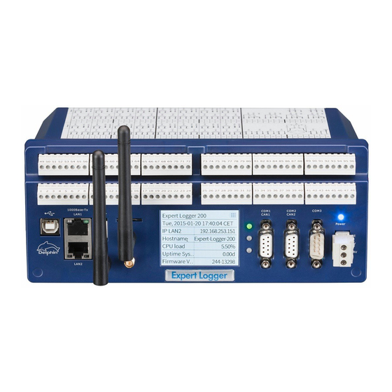
Expert Logger Gateway The views and functions for setting the gateway correspond to those for set- ting the IP address (see above). Note: A gateway address is required only if connections are to be estab- lished to other networks. 4.3 Configuring and operating the display In addition to the network configuration described in the previous Section, various additional information is available via the navigation area at the top right of the device display, which is described in this Section. Homescreen Tap the top right hand corner to call up the start (home) page: → Configure the lines shown here in System Display in DataService Con- Display figurator, see . Seven lines can be displayed. Channel view Tapping the icon takes you to a view containing the current device channel contents: Expert Logger Manual Delphin Technology AG Januar 2018... -
Page 33: Configuration Via An Internet Browser
4.4 Configuration via an Internet browser The Web configuration is performed by entering the IP address (or the DNS name for networks) in the browser's address bar. Any current browser can be used. Cookies are not required for the functions and JavaScript is used only for date and time settings. Info To return to the main page either click the Back button on your browser or click Back right at the bottom of the respective window. Con- Settings via the Web interface are made in the following four sections: figuration Service System , and . To display current status of the NTP or NTP/PTP status PTP client click on the respective link, see . Most of the set- tings made through the Web interface can also be made via the DataSer- vice Configurator. Expert Log- Example: Internet browser display for a device with name “ -SN12345678” and IP address 192.168.251.252. Expert Logger Manual Delphin Technology AG Januar 2018... -
Page 34: Configuration
Expert Logger 4.4.1 Configuration In this area you can: Show configuration table displays the current channel settings. You can view current values for individual channels (tracks) using Live chan- nel values. Use Channel default configuration to reset all channel settings to factory set- tings. System channels and network settings are maintained. Expert Logger Manual Delphin Technology AG Januar 2018... -
Page 35: Channels Overview (Show Configuration Table)
Expert Logger Use Factory default configuration to reset everything to factory settings, including the system channels and network settings. This then corresponds to the device’s condition with the firmware at the time of delivery. 4.4.1.1 Channels overview (Show configuration table) This window shows, in tabular form, the configurations of all the channels of the device. Each column contains detailed information such as channel name, type of module, physical unit, measurement range, or whether an invalid channel configuration exists, etc. The object ID in the penultimate column enables you to display the channel configuration as an XML file (potentially important for support purposes). The data can be displayed only. Changing settings is not possible. To change configurations, use the DataService Configurator program. The following figure shows a channels overview example (extract): 4.4.1.2 View current values (live channel values) This allows you to display current values of all or a selection of channels (tracks). In the Filter area you can select the signals or values to be dis- played. Change the sorting (ascending/descending) by clicking any column header. Expert Logger Manual Delphin Technology AG Januar 2018... -
Page 36: Resetting Configuration
Expert Logger The following figure shows an example (extract): 4.4.1.3 Resetting configuration Resetting the configuration to the factory setting can only be done through the Web interface. Resetting to factory setting cannot be undone. Channel default configuration By clicking all channel settings are reset to factory settings. All the channels you created will be deleted. Factory default configuration By clicking , all channels and all settings are reset to factory settings, including the system channels and network set- tings. All the channels you created will be deleted. This then corresponds to the device’s condition with the firmware at the time of delivery. The process is displayed in a window: Expert Logger Manual Delphin Technology AG Januar 2018... -
Page 37: Service
The file is required only by Delphin service and support in the event that the device malfunctions. Display information about your browser, the settings used and the (server) settings of the device via Browser information. You can also use this dialogue to test the speed of the data transfer. Download Hardware test certificate that documents the results of the hard- ware test. The test is carried out after the hardware has been manufactured. Downloading the PuTTY terminal program (PuTTY) button. The PROFIBUS GSD file displays the "PROFIBUS GSD file" on the next page for integrating the -Expert Logger - device into a PROFIBUS network (clicking) or saves it to a PC (context menu, Save target as). You can also download bit- maps from the device using this dialogue. Bitmaps are used for the graphical representation of the device in the user's PROFIBUS configuration program. Copy an XML network configuration template to the PC. This way, you can set a device’s network settings to appropriate values without having to connect to the device. Specify the new settings in the file and transfer the file to a device using a USB memory stick Using "USB network driver" on page 39, download a driver for the USB inter- face for your PC operating system, which enables communication such as via Ethernet (but not at the same speed). Expert Logger Manual Delphin Technology AG Januar 2018... -
Page 38: System Report
Logger 4.4.2.1 System report Delphin Provides a detailed overview of the system for fault diagnosis by Support. Send the file to the Support team. The system report can be gen- erated only through the Web interface. System report After clicking , the device requires approximately 15 seconds to acquire all the information and record it to a ZIP file. Depending on your browser settings, the following dialog for example is then dis- played to select the file save location. The file name is made up of the cur- rent date and time and the network identifier of the device. 4.4.2.2 PROFIBUS GSD file The PROFIBUS GSD file is required to configure the device in the PROFIBUS configuration software of the PROFIBUS Master. PROFIBUS GSD file Click to display the GSD file in your browser. Right click and select Save as from the context menu to save the file and to enable it to be copied to a PC with your PROFIBUS configuration program. The saved bitmaps optional for correct graphical representation of the device in the PROFIBUS configuration program. Download the GSD file via the Web interface or copy it from the /firm- ware directory of the installation CD. The following is an example of a GSD file (only the beginning is shown): Expert Logger Manual Delphin Technology AG Januar 2018... -
Page 39: Xml Network Configuration Template
Method 1. Save the file to your PC (right click on the link). 2. Open the file using an editor. 3. Change entries DefaultGateway=’192.168.0.254’, IPV4_ Address=’192.168.0.1’ and IPV4_NetMask=’255.255.255.0’ to your required values or change DHCP_active=’false’ to DHCP_active=’true’. 4. Save the amended file to a USB memory stick. 5. Plug the USB memory stick in to the device. 6. Switch on the device. 4.4.2.4 USB network driver When connecting the device to a computer via the USB interface, the required driver is automatically installed. Connecting to the device Enter the IP address of the device in DataService Configurator. If you are not sure about the address: 1. Open the Network and Sharing Center of your PC via Control Panel. 2. Click Change adapter settings. Expert Logger Manual Delphin Technology AG Januar 2018... -
Page 40: System
192.168.7.2. Refer also to "USB device" on page 239. 4.4.3 System In this area you can: Firmware updating using Update firmwareMetiOS (updating of the software within the device). See Update firmware. Displaying of the changes to the current firmware compared to the previous version using MetiOSchangelog. Adobe Acrobat Reader is required. The Acrobat Reader can be downloaded (free) from the Adobe website. See Updating firmware. Restarting the device using Reboot. This has the effect of switching the device off and on. See Rebooting the device. Restart server restarts the software only for data acquisition and storage or transmission. See Restart server. This is faster than a reboot (full restart) of the device. Recalibrate touch screen Calls a dialogue where you must tap the points displayed in the four corners of the screen. This improves and/or restores the accuracy of tapping text or graphics on the screen. Expert Logger Manual Delphin Technology AG Januar 2018... -
Page 41: Update Firmware
New firmware file Enter the file with the new firmware in the input field Browse Start firmware (click to locate the file on your PC) and then click update . The firmware upgrade takes approximately 2 to 3 minutes. 4.4.3.2 Firmware changelog Firmware changelog Click to display a PDF file containing information on how the current firmware differs from previous versions. Adobe Acrobat Expert Logger Manual Delphin Technology AG Januar 2018... -
Page 42: Device Restart (Reboot)
4.4.3.4 Restart measurement data acquisition (restart server) Restart server Clicking restarts the main program (application), which Reboot acquires and processes measurement data. This is faster than a (full restart) of the device. During the restart, data is neither acquired nor stored. The network connection to the device is interrupted and re-established following the restart. Expert Logger Manual Delphin Technology AG Januar 2018... -
Page 43: Connecting Slave Devices
The DCP CAN bus for I/O extensions uses the "Ext. BUS" port. If a ProfiMessage device has an insufficient number or type of input chan- ProfiMessage nels, a slave device can then be connected to the device Device connections via this port. (Refer to Connecting the extension bus Use twisted pair shielded cable (e.g. braided LiYCY 2x0.14 mm2 TP). Ensure that the start and end connections (i.e. at the master and at the final slave device) use the supplied 120-ohm resistors. These produce the bus signal level and prevent interference from signal reflection. The Hi (CAN High) designated ports must be connected to other devices via Hi, and Lo (CAN Low) with Lo. Illustration in DataService Configurator Channels The tab lists the modules currently connected according to the hardware view user-defined type of view selected ( or ) in the group "Extension (CAN) bus" group or as I/O modules from the (master) device. Expert Logger Manual Delphin Technology AG Januar 2018... - Page 44 Expert Logger Configuring module channels I/O module configuration is explained in Configuring the extension bus The extension bus protocol cannot be changed and is set to Delphin CAN Protocol). Expert Logger Manual Delphin Technology AG Januar 2018...
-
Page 45: Configuring The Expert Logger Device Via The Dataser- Vice Configurator
Expert Logger 4.6 Configuring the device via the DataSer- vice Configurator user-defined view The next level in the (top image) displays the software channels, the System monitoring, the I/O channels, the interfaces and the hardware view memory.DataService Configurator In the (bottom image), after the software channels, the System monitoring, the different inter- faces, the I/O channels, the memory and the USB interfaces are dis- hardware view played. In the (bottom image), after the software channels, the system monitoring, the different interfaces, the I/O chan- nels, the memory, and the USB interfaces are displayed. User -defined view Hardware view Expert Logger Manual Delphin Technology AG Januar 2018... -
Page 46: Settings For All Dialogues
Use the Properties context menu to amend a device name and ID or to enter a description for the device. Use Main settings context menu to change network and NTP settings. Configuring main device Network settings, NTP Refer to , For explanations of other settings, see: Configuring software channels Section for system monitoring and cal- culations, Configuring channels (sensors) Section for the I/O channels, Configuring interfaces Section for the CAN, COM and PROFIBUS interfaces, Memory Section for the internal memory. Info For general information on configuration dialogs (including header and footer), see Settings for all dialogs. 4.7 Settings for all dialogues A configuration dialogue for the relevant item (channel) opens after double-clicking one of the channels, an interface or another item in the channel list. Different tabs are displayed depending on the channel type. The listings in the tabs also depend on the channel type. Many of the set- tings are the same for all dialogues, especially in the upper and lower sec- tions, and are hence explained here in general terms. Expert Logger Manual Delphin Technology AG Januar 2018... - Page 47 Expert Logger Upper section Active : Enables or disables the channel. Channel name : Enter a meaningful and unique name to identify the chan- nel. Unit : Enter the unit of measurement. Expert Logger Manual Delphin Technology AG Januar 2018...
-
Page 48: Additional Settings Tab
: Opens online help. The relevant topic is displayed where available. The date and time display of the last setting change for the channel is dis- played in the lower left corner (15.6.2015 in the example). Tabs in the dialogue's main section Depending on the type of channel, different tabs are available. Not all the tabs are available for every channel type. The following (general) tabs are explained in this section as they are very similar for different devices. Additional settings Sensor compensation Information Main settings The tab is always specific to the channel. It can hence be found under the relevant device- and channel type. There are also other Extended settings Filter tabs that relate to specific channels, e.g., or and are, therefore, described under these channels. 4.7.1 Additional settings tab Expert Logger Manual Delphin Technology AG Januar 2018... - Page 49 Expert Logger Replacement value : This is used in the event of an input or output failure Status monitoring (refer also to ). The settings depend on channel type. For example, digital inputs only have the options Off and On. Force substitute value (simulation): Sets the channel's output value to the given substitute value. This setting is useful during installation to sim- ulate certain conditions or activate system responses. Do not forget to disable the option for normal operation! Inherited validity range (not available for all channel types): Enter the valid range in which measurement values are valid. Depending on the channel type, the validity range can be optionally inher- ited. If the validity range can be inherited, the validity will be adopted, Main settings depending on the channel type, either from scaling (see tab) or the data source of the channel. Expert Logger Manual Delphin Technology AG Januar 2018...
-
Page 50: Sensor Compensation Tab
Data reduction than 0.1 mA from the preceding value. The function reduces the data rate on the interface and thus assists the PC in the further processing. The internal processing of measurement values is not affected by this. The tolerance value can be expressed as an absolute measurement unit or validity range as a relative value in relation to the . Some channel types do not have a validity range and, therefore, you can only give the tolerance value as an absolute measurement unit of the channel. Formatting (not available for all channel types): Here the resolution for the channel’s values can be set. Persistence (not available for all channel types): The currently valid output value (refer to data reduction) is stored to a non-volatile memory. The channel uses this value following a restart or power outage. This function is particularly important for outputs in order to establish a defined state fol- lowing power outage. 4.7.2 Sensor compensation tab In this tab you can specify corrections for sensors or analogue outputs. accor Main settings Conversion takes place ding to scaling settings in the tab for the signal delivered by the sensor. Expert Logger Manual Delphin Technology AG Januar 2018... - Page 51 Expert Logger Active : Enables sensor compensation. Mode : There is a choice of modes Offset An offset shifts the curve by a fixed value, for example the given value is added to the measurement value. Offset and slope Allows a shifting of the curve and an increase in its slope. Quadratic Generates a quadratic curve through the given points to linearise the meas- ured values. Linear interpolation Set a table for converting measured values into display values. Linear inter- polation takes place between the given points. Expert Logger Manual Delphin Technology AG Januar 2018...
-
Page 52: Information Tab
Expert Logger Spline interpolation An optimal fitting polynomial 3rd degree (cubic spline) is determined using spline interpolation for the given values which is then used to to convert the measured values. Info You can use copy and paste to transfer data from an Excel table into the dialog table. Position the cursor in the table's top left field of the first row. Extra rows are created automatically when this is permitted by the selected mode. Click on a row and use the Del key to delete unwanted rows. Insert extra rows in a linear interpolation using the Return key. A created table can be exported and then re-imported later: Export and Import. 4.7.3 Information tab Expert Logger Manual Delphin Technology AG Januar 2018... -
Page 53: Basic Channel Selection
Expert Logger The tab shows you the channels dependent on a channel or an event. 4.7.4 Basic channel selection Many dialogues require a channel to be selected as a source or a target. A advanced channel selection basic or is thus available. The basic channel selection is accessed directly from the configuration dia- logue. All configured channels are listed by clicking the arrow on the drop- down list: Click the required channel. If the channel name is known, it can be input from the keyboard. The list is filtered down while letters are keyed in, which makes selection easier. 4.7.5 Advanced channel selection This method of display and selection is more convenient for a large num- ber of configured channels because the advanced filtering function enables only specific channels to be searched and displayed. Open the dialogue box by clicking on (the symbol is shown next to the entry field). The channels are displayed by name, description and channel Expert Logger Manual Delphin Technology AG Januar 2018... -
Page 54: Trigger Options
Expert Logger Advanced search Enter a filter criterion in the field. The relevant selection then appears in the upper section of the dialogue. Selected the required channel and click 4.7.6 Trigger options Many dialogues have input fields with options for different trigger functions according to edge or level states. The following options and combinations are available: Expert Logger Manual Delphin Technology AG Januar 2018... -
Page 55: Inherit Status
Falling The event is triggered when changing from "High" to "Low" edge Edge The event is triggered at every change (both) High The event is triggered when (and for as long as) the level is level "High" Low The event is triggered when (and for as long as) the level is level "Low" Every The event is triggered for each value larger than 0. The function high is generally only recommended with digital signals. Every The event is triggered for each value that is 0. The function is only recommended with digital signals. Every The event is triggered as soon as there is a (new) value. value 4.7.7 Inherit status This option sets whether the source's status as well as its value is to be used for the function. This can be used, for example, to prevent invalid input values in the calculation. Channel status values are available in status monitoring. An example of inheriting: The case of an analogue input exceeding a range is displayed in the software channel as a wire break. Expert Logger Manual Delphin Technology AG Januar 2018... -
Page 56: Device Properties Context Menu
Expert Logger 4.8 Device Properties context menu The device’s context menu allows you access to various settings, which are valid for the device as a whole and therefore also for all channels: Set (device) properties, for example, the device ID or location. Save and load configurations (you may use the configuration also in offline mode). Creating the network configuration 4.8.1 Configuring device properties Open the configuration dialogue either by double clicking the device or by opening the dialogue via Properties from the context menu. This dialogue enables users to: Expert Logger Manual Delphin Technology AG Januar 2018... -
Page 57: Saving And Loading Device Configurations
2. Enable User-defined device ID. 3. Enter a new ID (e.g. the device's " old" serial number). The device ID is in hexadecimal format. Valid inputs include numbers from 0 to 9 and letters from 'a–f' or 'A–F' (no distinction is made between upper case and lower case letters). If a sufficient number of characters is entered, preceding zeroes are removed. A valid input changes the input font from red to black. After amending the device ID, the connection to the d evice is briefly inter- rupted before being restored again. Settings for all dialogues Refer also to 4.8.2 Saving and loading device configurations Save configuration Open the dialog via the device's context menu. Enter the destination file in the file dialog. Thereafter you can enter a description of the configuration to be saved (comment). This will be dis- played when you load the file. Load configuration Open the dialog via the device's context menu. Select the configuration file to be loaded. You may only load configurations you have generated using the Save configuration menu. Configuration Expert Logger Manual Delphin Technology AG Januar 2018... - Page 58 Expert Logger files which you have previously saved via the device's Web interface can- not be loaded via this menu. The description saved with the file will be shown and you will be shown the various options. Info Not all options are available for every device. Loading channels All configuration file channels are loaded to the device. Any existing device channel configurations will be overwritten. Restoring persistent measurement values The tracks marked as persistent are set to the value stored in the file. "Additional settings tab" on page 48 Refer to Loading/restoring a unique device ID The factory setting for the device ID is generally its serial number. This ensures that the device’s channel ID is globally unique. Select this option to use an existing configuration in for example a replacement device, Expert Logger Manual Delphin Technology AG Januar 2018...
-
Page 59: Creating The Network Configuration
Keep current device IP address/mask/gateway If this option is enabled, the standard network settings are not loaded. Otherwise it could happen that a network configuration is loaded to your device, that will render your device unreachable from your IP range, or the device could receive an IP address which is already allocated to another device, causing a network conflict. Disabling access protection during loading Any access protection is disabled temporarily during the loading process, so that the setting in the file can be imported. 4.8.3 Creating the network configuration This menu is used to create a network configuration. A network configuration allows you to change the network settings of a device without connecting to a PC. This is especially helpful if you want to configure multiple devices. You can modify the file for each device and save it to a USB memory stick. When the USB memory stick is connected to a device, this file is read and the device obtains the settings from the file. Method Expert Logger Manual Delphin Technology AG Januar 2018... -
Page 60: System Channels
SN00000000.xml" link. Also visit the XML Template for Network Configuration Help Centre. 4.9 System channels This Section explains the settings for the System group. The settings for "Drives" on page drives available only for expert devices can be found in 4.9.1 Time and clock settings In this group, some channels are already set by default, which are relevant to the time and date settings: Battery OK (a System Monitor software channel setting) Clock frequency error, Stratum (synchronisation chain) or Sync (syn- chronisation available) are Clock software channel settings Time (zone) and clock (synchronisation) settings (the channel is also avail- able as a copy in Network settings) Synchronisation via NTP The NPT time (Network Time Protocol) is a number that contains the num- ber of seconds that have passed since midnight (00:00 h) on 1 January 1970, with a resolution greater than one microsecond. The NPT time refers to GMT (Greenwich Mean Time). http://www.meinberg.de Further information is available from and http://www.pool.ntp.org Expert Logger Manual Delphin Technology AG Januar 2018... - Page 61 GPS antenna WWAN connection of the device and activate here Once the GPS receiver receives a valid satellite signal, after a short time NTP status will display ‘Synchronized to UHF radio at stratum 1’ Use Data Service/Local Clock . You can also enable direct synchronisation with a connected DataService without using a NTP server. Thus, the current time of the device’s con- nected PC is used as a reference and the device begins to set itself to this DataService time. This process may take more than an hour. Select the setting. Only use this setting when no NTP server is available on your net- work. The time will be as accurate as that of the PC connected to the device. Also synchronise large time differences This setting enables NTP server time setting, even where there is a large deviation between the current device time and the NTP time. This option is Expert Logger Manual Delphin Technology AG Januar 2018...
- Page 62 Expert Logger helpful where the device was not registered on the network for a period of time and, for example, has the wrong date. Overall NTP allows a deviation of less than 1 ms to be reached. Incorrect time synchronisation Example of absent or incorrect time synchronisation DataService Con- figurator: Setting the time zone Time and Clock Settings In the dialog, enter the device time zone. Other- wise, the unadjusted time (GMT) will be used. For the UK, enter . Alternatively, you can enter one of the entries for UK/London the UK, for example, . If you operate the device in a different time zone, you can also set the required time difference from GMT (Green- wich Mean Time) for that country, or a country within the same time zone, in this field. Expert Logger Manual Delphin Technology AG Januar 2018...
- Page 63 Expert Logger Info There is no automatic setting of daylight saving time (e.g., CET to CEST). Synchronisation via PTP In addition, as an alternative to NTP (or GPS), you can use PTP (Precision Time Protocol). PTP time deviations are often less than with NTP, however Delphin you require either a PTP server on your network or an additional Master Slave device. You can designate one device as and the other as . If the master device additionally receives the exact time via NTP, all devices will use the most accurate (as possible) NTP time, but are synchronised (usually better) with each other via PTP. Expert Logger Manual Delphin Technology AG Januar 2018...
-
Page 64: Directory (User Management)
. Set the to the required level. Administrator The Administrator has the rights to update all device settings. The default password is SUPERVISOR. root Has the same rights as the Administrator, but in addition has permission to log in to the operating system console. The default password is ‘root’. Important For security reasons, change the device’s Administrator and root passwords once User management is enabled. Create new entry → You can create a new entry in the context menu Create User in Dir- ectory. User class User Group First, specify the : adds a new user, is helpful when Login data several users are to log on with the same name, creates an entry that you can use to log the device into a mail server, for example. Expert Logger Manual Delphin Technology AG Januar 2018... - Page 65 Logger username user right Then, specify the login name ( ), the and the password . You must enter the password twice to prevent typing errors from occurring. Only once both entries are identical will the red back- Store password unencrypted ground colour be removed. If you enable , the password is stored and transmitted unencrypted. Real name Enter the user’s full name in connection to localhost If you limit the , this user will be able to work only locally, that is, not via one of the interfaces. For example, use could be lim- ited to display (not yet implemented at this time). If required, you can also store up to three telephone numbers and three e- mail addresses per user. Click for additional input fields. Close the dia- log with Activate user Expert Logger Manual Delphin Technology AG Januar 2018...
- Page 66 , , figurator Administrator or an additional Monitor Members can, for example, display current measurement data in DataSer- vice Configurator. Evaluator Members can analyse measurement data and evaluate reports. Operator Members can operate elements and, for example, switch device outputs. Configurator ProfiSignal Members can create and configure applications. Administrator Members can manage users, set up password protection and make other administrative settings. Root Has the same rights as the Administrator, but in addition has permission to log in to the operating system console. Enter a phone number It is recommended to enter telephone numbers in international format according to E.123. This format indicates the country code with a ‘+’. Furthermore, the number can be separated by blanks to improve read- ability. Example: +49 2204 976850 Expert Logger Manual Delphin Technology AG Januar 2018...
-
Page 67: Display
Expert Logger 4.9.3 Display See also for the display backlight brightness. → You can configure the display home view under System Display and the Properties context menu for each line. Own host name Displays the device network host name. IP address, MAC Select the interface for which you wish to display information. The line then displays either the IP address or MAC address (Media Access Control address) used for the interface. The MAC address identifier is defined via the (hardware) adapter and is required if the network administrator wants to assign a specific IP address to a device, as opposed to via DHCP. Expert Logger Manual Delphin Technology AG Januar 2018... -
Page 68: Drives
to define whether the output value is to be handled as a Float (text) or (numeric value). 4.9.4 Drives Specify here which drives should be available for data saving. "Device memory" on page 251 Refer to USBdrive Once you have connected a memory, for example, a USB memory stick or a USB drive with the USB interface, the memory will be displayed as a drive and can be selected here. USB device Refer also to The USB storage must be configured with the FAT32 filesystem; other file systems are not recognised. Expert Logger Manual Delphin Technology AG Januar 2018... - Page 69 Expert Logger Only allow following devices You can either select and enter the device (you may add multiple drives). If the memory is formatted with multiple Partition number partitions, you can also enter the . Alternatively, you can Next available device select , and then one of the other memories will be used (if available), as soon as the current one runs out of space. Network drive Expert Logger Manual Delphin Technology AG Januar 2018...
- Page 70 Expert Logger Choose the file system or protocol for addressing the network drive. (Network File System) enables file access via a network. Choosing this means that the files are not transmitted via for example FTP, but instead you can locate and access files saved on another PC, as if they were located on the local drive. CIFS (Common Internet File System) is based on NetBIOS over TCP/IP and SMB and offers other services such as Windows RPC and NT Domain in addition to the file functions. (File Transfer Protocol) is a widely used network protocol used to trans- fer files and manage directories (create, delete, etc.). SFTP (Secure File Transfer Protocol) allows a more variable encryption of data transfer than FTP. Expert Logger Manual Delphin Technology AG Januar 2018...
-
Page 71: Led
Expert Logger network address path For all options you need to specify the and for access. For NFS, also the protocol version to be used (v2 or v3). If authen- user tication is required for other methods, you must enter the . The user "Directory (User management)" on page 64 must be created via 4.9.5 The LED group allows you to specify the display backlight brightness and the assignment of the LEDS, for example, when and which LED illuminates red or green. source Select the desired and specify for each source, whether the for example an interface or channel should send the information. Channel Select an available channel whose value is to be output using in Source Manual value Application , or enter a constant value ( ). Selecting Expert Logger Manual Delphin Technology AG Januar 2018... -
Page 72: System Monitoring
System Display of time that the operating system has been operating working, as in the time since the device was last Days time switched on. Display of time that the main program has been Application Restart main applic- operating working, as in the time since Days time ation Reboot or switching on or of the device. Data stor- Amount of memory already used for the data. age used Free data Amount of memory available for the data. storage Firmware Device firmware version number. — version CPU tem- Temperature of the CPU. °C perature Expert Logger Manual Delphin Technology AG Januar 2018... -
Page 73: Network Settings
Expert Logger Selection Description Unit Core CPU core voltage, diagnostic value. voltage Core RAM Internal value for diagnostics only. voltage Aux voltage Internal value for diagnostics only. Display whether the backup battery for the real-time Battery OK — clock and the SRAM is working. MiB = 1024 x 1024 byte (Mebibyte, actual storage capacity); MB = 1000 x 1000 byte (Megabyte). A hard disk with 500 MB (according to the man- ufacturer) can therefore effectively only save 476 MiB (500,000,000/(1024 x 1024)). 4.9.7 Network settings Info The “Network settings” group is by default available both in the “Sys- tem” and “Interfaces” groups. Display the dialog via the Properties context menu. Expert Logger Manual Delphin Technology AG Januar 2018... - Page 74 Expert Logger Hostname domain DNS server The (network name for the device), and field inputs are used to convert network names into the corresponding IP address. Leave the DNS server field empty when a DNS server is unavail- able on the network. Do not use invalid characters for network host and domain names (no underscores or special characters and only ASCII characters, as in, no Ger- man umlauts, etc., but hyphens are allowed). Server services Here you can see which ports are used for the various server services. The ports themselves cannot be changed. You can however deactivate ser- vices which are not required. HTTP is required for the Web interface (for example firmware update), but can however be switched off when not required. Expert Logger Manual Delphin Technology AG Januar 2018...
-
Page 75: Mail Settings
(PoND interchange Message Protocol) is permanently required by the DataService and cannot therefore be deactivated. XiMP (XML interchange Message Protocol) transfers data in the same way as the DataService, except in XML format. WiMP (Web interchange Message Protocol) is required; for example, for Live channel values channel representation ( ) in your Internet browser. PTerm is used only in debug mode for Telnet transfers and is therefore not active in the default setting. Ports ports Delphin List of all used by Info Please note that changing the permitted protocols can affect the func- tioning of the device and may completely block access to the device in combination with firewalls, managed switches etc.! 4.9.7.1 Mail settings No settings possible here! The mail servers can be created under this channel. Mail server Specify a mail server for sending mails. Info If your mail server requires user authentication, create the necessary login data via "Directory (User management)" on page 64 before call- ing the mail server dialogue. Expert Logger Manual Delphin Technology AG Januar 2018... - Page 76 Expert Logger Main settings tab Expert Logger Manual Delphin Technology AG Januar 2018...
- Page 77 Expert Logger Mail server: This section is used to specify the connection settings of the mail server. Address: Enter the address of the mail server to be used. Port: Enter the port of your SMTP server. Security: Select the encryption protocol of the mail server. The encryption protocol for your mail server is available from your IT or e-mail provider. Please note: Public mail servers generally no longer allow unencrypted protocols. User authentication: If the mail server requires authentication via login data, enable the check mark for user authentication. Now select the user. Please note that you have created the user in the Directory section of the devices before open- ing the mail server dialogue. Standard: Select this check mark if the mail server is to be used as the default mail server. In the appropriate configuration dialogues, you can specify a mail server manually as well as the use of a default mail server. Format sender address Expert Logger Manual Delphin Technology AG Januar 2018...
- Page 78 Port Encryption? The following can be configured: none, TLS or SSL Authentication necessary on the mail server? What are the recipient addresses? Creating the mail server in the channel structure Before the mail server is created, check whether login data is required. If the mail server to be used requires authentication by means of login data, this must be cre- ated first. Please follow the descriptions in theCreate login data section and then continue with Create mail server. If no authentication is required, please skip theCreate login data section and con- tinue with theCreate mail server section. Creating login data Expert Logger Manual Delphin Technology AG Januar 2018...
- Page 79 Expert Logger In the channel tree, open the System folder. Right-clicking Directory allows you to create a new user. Expert Logger Manual Delphin Technology AG Januar 2018...
- Page 80 Expert Logger The following settings must be entered in the Basic Settings tab: Enter the authentication login name under Username. For user class, please select Login data. In the fields New Password and Repeat, enter the password required for authen- tication. Now confirm the dialogue by clicking OK. Creating the mail server Expert Logger Manual Delphin Technology AG Januar 2018...
- Page 81 Expert Logger In the channel tree, open the System folder, then Network Settings and, under it, Mail Settings. By right-clicking Mail Settings, you can create a new mail server. Expert Logger Manual Delphin Technology AG Januar 2018...
- Page 82 Expert Logger Assign a suitable channel name to the mail server. Furthermore, the following set- tings must be entered in the Basic Settings tab: Enter the mail server address in the Address field. Enter the port of the mail server in the Port field. Select the encryption that is specified by the mail server. (None, TLS or SSL) If user authentication is required, please check theUser authentication box and select the user with the stored login data from the list. Expert Logger Manual Delphin Technology AG Januar 2018...
- Page 83 You can manually determine the mail address by changing the fields domain (for the global part) and username (for the local part). Furthermore, the field Displayed name offers the option to store a real name. This can be displayed in mail programs instead of the complete mail address. Please note: Some mail servers prohibit a mail address that differs from the login name. Setting the default mail server System Network Settings In the channel tree, open the folder, then and, Mail Settings Mail Settings under it, . Double-clicking opens the dialogue Mail Settings of the . Here, you can set a default mail server. Expert Logger Manual Delphin Technology AG Januar 2018...
- Page 84 Expert Logger Expert Logger Manual Delphin Technology AG Januar 2018...
- Page 85 Expert Logger Creating recipients In the channel tree, open the System folder. Right-clicking Directory allows you to create a new user. Expert Logger Manual Delphin Technology AG Januar 2018...
- Page 86 Expert Logger The following settings must be entered in the Basic Settings tab: Enter the desired username under Username. For user class, please select User. In the E-mail section, enter the appropriate mail address of the user. Now confirm the dialogue by clicking OK. Repeat this step until you have created all the desired recipients. Expert Logger Manual Delphin Technology AG Januar 2018...
- Page 87 Expert Logger Creating the event channel In the channel tree, navigate to the location where you want to create the event channel. In the above example, an event channel is created below Software chan- nels. Expert Logger Manual Delphin Technology AG Januar 2018...
- Page 88 Expert Logger The following settings must be entered in the Basic Settings tab: Under Source, select the trigger of the event. You can add the desired mail recipients in the Recipients section. The Type is used to determine whether the receiver should be a main receiver (To), a sec- ondary receiver (CC) or the receiver of a blind copy (BCC). In the Message content section, you can specify the subject and message content. In the Variables/Mail server tab, the following settings are mandatory: Select whether this event channel should use the default mail server or a manually defined mail server. Now confirm the dialogue by clicking OK. You have now configured a mail dispatch. As soon as the source of the event chan- nel triggers an event, a mail is sent to the configured addressees. Expert Logger Manual Delphin Technology AG Januar 2018...
-
Page 89: Time And Clock Settings
Expert Logger 4.9.7.2 Time and clock settings System → Clock → Time and The dialogue is identical to the dialogue for Clock Settings "Time and clock settings" on page 60 , refer to . The dia- logue is found here again, for example, because the NTP servers can be reached via the Ethernet interface and the setting, therefore, could also be searched under Interfaces. 4.9.8 Power saving The Power Saving Properties dialog allows you to wake the device only at certain times or in response to certain events, and to enable the power sav- ing mode at other times. Expert Logger Manual Delphin Technology AG Januar 2018... -
Page 90: System Settings
Expert Logger You can create further conditions to prevent shutdown or to trigger imme- Trigger variants edge and level diate shutdown, see also Active time sets a minimum period for which the device operates. To prevent shutdown from interrupting an existing DataService connection following a signal or once the Active time duration has elapsed, you should enable the corresponding option at the bottom of the dialog. 4.9.9 System Settings This dialog allows you to enable the device’s User management. Open the dialog from the context menu. "Directory (User management)" on page 64 Refer also to Anonymous login Expert Logger Manual Delphin Technology AG Januar 2018... -
Page 91: Configuring Channels (Sensors)
Specifies the default unit to be applied to temperature measurements. But you can use different units for each channel. This specifies only the unit; units are not converted. 4.10 Configuring channels (sensors) software channels interfaces Configuration of , (for external devices) and device memory is described in separate sections. Settings for all dialogs Overview Galvanic isolation See also , , Expert Logger The device has the following I/O channels: Analogue Input Analogue output Digital input Digital output Expert Logger Manual Delphin Technology AG Januar 2018... -
Page 92: Analogue Inputs (Expert Logger)
Expert Logger 4.10.1 Analogue inputs ( Settings for all dialogues Galvanic isolation Refer also to , Method 1. Specify the sensor type and sensor measurement range settings in the Propertiescontext menu of the respective inputs. Configuration options in the Main settings tab of the dialog depend on the sensor type, and are explained in the following separate sections: 2. If necessary, enter on the Sensor compensation tab a characteristic curve correction, see "Sensor compensation tab" on page 50. 3. Specify on the Additional settings tab replacement value, validity range and data reduction, see "Additional settings tab" on page 48. 4. Check whether, on the Advanced settings tab, you need to enter inform- ation, for example, for monitoring the signal, see Advanced settings tab. Expert Logger Manual Delphin Technology AG Januar 2018... -
Page 93: Voltage Sensor Type
Expert Logger 4.10.1.1 Voltage sensor type The example means: 0 mV corresponds to 0 bar, 5 V corresponds to 10 bar. Mode unipolar : Measuring only positive signals. bipolar : Measuring positive and/or negative signals. Measuring range Select a measuring range that is equal to or greater than the signal from the sensor or signal source to prevent A/D converter overload. The chan- nel receives the status ‘Measurement range overrun/underrun’ for Expert Logger Manual Delphin Technology AG Januar 2018... -
Page 94: Sensor Type Current 0/4 Ma To 20 Ma
Expert Logger measurements not within the range. Channel status values are available in status monitoring. Scaling Enter two points from the sensor's characteristic curve, if possible, the lower and upper vertexes. For a linear characteristic, measurement values are then converted into the unit of measurement (scaling) from the sensor. Sensor compensation Sensor com- For non-linear characteristics use . See pensation tab. The specified range (in the example 0bar to 10bar) is used ProfiSignal as the default for the graphic display area. The channel receives the status "scale range overrun" or "scale range underrun" when not within the range. Channel status values are available in the table in Status monitoring 4.10.1.2 Sensor type current 0/4 mA to 20 mA Expert Logger Manual Delphin Technology AG Januar 2018... -
Page 95: Resistance Sensor Type
Current measurement is not possible without load res- istance. Scaling Enter two points from the sensor's characteristic curve, if possible, the lower and upper vertexes. For a linear characteristic, measurement values are then converted into the unit of measurement (scaling) from the Sensor compensation sensor. For non-linear characteristics use . See Sensor compensation tab. The specified range (in the example 0 l/h to ProfiSignal 1000 l/h) is used as the default for the graphic display area. The channel receives the status "scale range overrun" or "scale range underrun" when not within the range. Channel status values are available Status monitoring in the table in 4.10.1.3 Resistance sensor type Advanced settings See also the tab Expert Logger Manual Delphin Technology AG Januar 2018... - Page 96 Expert Logger The example means: 0 degrees corresponds to 0 ohms, 4000 ohms cor- responds to 270 degrees. Measuring range Select a measuring range that is equal to or greater than the resistance from the sensor to prevent A/D converter overload. The channel receives the status ‘Measurement range overrun/underrun’ for measurements not status mon- within the range. Channel status values are available in itoring. Scaling Enter two points from the sensor's characteristic curve, if possible, the lower and upper vertexes. For a linear characteristic, measurement values Expert Logger Manual Delphin Technology AG Januar 2018...
-
Page 97: Resistance Thermometer Sensor Type
Status monitoring available in the table in Connection Indicate here how the sensor has been connected (the diagram displays the selected wiring): 2 Wire : The sensor is connected with only two wires. This is recommended only for very short lines and high impedance sensors, otherwise the res- ulting voltage drop across the circuits can lead to more substantial meas- urement errors (cable resistance is factored into the measurement). 3 Wire : The device attempts to compensate the voltage drop via the sup- Expert Logger ply lines. devices, in particular, can thus lower sub- stantially the measurement error relative to the 2-wire circuit. 4 Wire : The recommended connection method for low impedance sensors and/or longer supply lines. The loss of feed lines does not matter because the device has a high-ohm input resistance (no voltage drop on the line feeds) and the voltage drop (the measurement value) can be measured directly at the sensor. 4.10.1.4 Resistance thermometer sensor type Advanced settings See also the tab Expert Logger Manual Delphin Technology AG Januar 2018... - Page 98 Expert Logger The example shows the settings for a Pt1000 sensor. The settings for Nixxx sensors or Pt100 etc. are however similar. Pt ... or Ni xxx or YSI400 Select the resistance thermometer type used: Pt100, Pt1000 etc. If you Pt xxx Ni xxx select or you can select the nominal resistance. (The numer- ical values for the platinum and nickel thermometers correspond to their resistance at 0°C.) YSI400 is a special NTC resistor mainly used in the medical field (tem- Ω Ω perature range -80 °C to 250 °C, resistance of 1660 to 6400 Measuring range Expert Logger Manual Delphin Technology AG Januar 2018...
-
Page 99: Thermocouple Sensor Type
: Rankine °R : Degrees Réaumur Connection Indicate here how the sensor has been connected (the diagram displays the selected wiring): 2 Wire : The sensor is connected with only two wires. This is recommended only for very short lines and high impedance sensors, otherwise the res- ulting voltage drop across the circuits can lead to more substantial meas- urement errors (cable resistance is factored into the measurement). 3 Wire : The device attempts to compensate the voltage drop via the sup- Expert Logger ply lines. devices, in particular, can thus lower sub- stantially the measurement error relative to the 2-wire circuit. 4 Wire : The recommended connection method for low impedance sensors and/or longer supply lines. The loss of feed lines does not matter because the device has a high-ohm input resistance (no voltage drop on the line feeds) and the voltage drop (the measurement value) can be measured directly at the sensor. 4.10.1.5 Thermocouple sensor type Advanced settings See also the tab Expert Logger Manual Delphin Technology AG Januar 2018... - Page 100 Expert Logger The example shows the settings for a type K thermocouple (NiCr-NiAl, nickel-chrome and nickel-aluminium alloy). Sensor type Select your thermocouple type. The letter type and material type of the thermocouple wires are given. Measuring range The maximum possible sensor measuring range is pre-selected. The chan- nel receives the status ‘Measurement range overrun/underrun’ for meas- urements not within the range. Channel status values are available in status monitoring. Unit Expert Logger Manual Delphin Technology AG Januar 2018...
-
Page 101: Ph Probe Sensor Type
Expert Logger Select the unit of measurement in which the temperature is to be dis- played. Conversion is performed automatically within the device. °C : Degrees Celsius : Kelvin °F : Degrees Fahrenheit : Rankine °R : Degrees Réaumur Info Enter the reference junction to be used in the Advanced settings tab. See Reference junction. 4.10.1.6 Ph probe sensor type Advanced settings See also the tab Expert Logger Manual Delphin Technology AG Januar 2018... - Page 102 Expert Logger This sensor type determines the pH value from the voltage of the pH probe in mV and the temperature in ° C of the reference junction via the Nernst factor. Nernst factor Nernst factor = ln10 * molar gas constant * absolute temperature / Faraday constant molar gas constant = 8.314472 in J/(mol*K), absolute temperature = temperature of the reference junction + 273.15 in K, Faraday constant = 96.4851534 in J/(mV*mol) Sensor type Select Expert Logger Manual Delphin Technology AG Januar 2018...
- Page 103 Expert Logger Temp. compensation Temperature compensation is determined by measuring the temperature at the measurement point in the solution to be determined. Activate com- Advanced settings pensation and configure the channel using the tab. See Reference junction Sensor measuring range A range of ±625 mV is sufficient for this sensor type. Scaling The default scaling uses the standard measurement methods and should not be altered. Expert Logger Manual Delphin Technology AG Januar 2018...
-
Page 104: Measuring Bridge Sensor Type
Expert Logger 4.10.1.7 Measuring bridge sensor type The example means: At a signal of 2.01523 mV/V, a force of 1000 N acts on the sensor. Scaling nominal load sensitivity Enter the and resulting signal of your sensor ( ). The output signal at nominal load is also referred to as gradient and is noted in the calibration record of the sensor. For a linear characteristic, measurement values are then converted into the unit of measurement Sensor com- (scaling) from the sensor. For non-linear characteristics use pensation "Sensor compensation tab" on page 50 . See tab. The spe- cified range (in the example, ±1000 N) is used as the default for the Expert Logger Manual Delphin Technology AG Januar 2018... -
Page 105: Configuring Digital Inputs
The is based on the sensor’s values specified in the technical data. Where possible, enter the maximum voltage in the nominal range of the sensor’s feed voltage. 4.10.2 Configuring digital inputs Settings for all dialogues Galvanic isolation Refer also to , Your device has ports that can be used only as digital inputs and ports that digital can be used both as inputs and as outputs. As long as you choose input mode as for these ports, these are identical to the pure inputs. Method for digital inputs 1. Specify the logical level for the input (normal or inverted). 2. Indicate which replacement value is to be used if the input fails. Refer to "Additional settings tab" on page 48. 3. Sets how the input should be used: for counting or for frequency meas- urement. Main settings tab Expert Logger Manual Delphin Technology AG Januar 2018... - Page 106 Expert Logger Debouncing : To hide short interference pulses, here you can specify a time period that you want to elapse before a signal is evaluated. Inverted : This option inverts a ‘high’ level at the input to a ‘low’ level at the output (measurement signal in device) and vice versa. Generating measurement data : When this option is enabled, all resulting measurement data is transferred, although, for example, in the DataSer- channels vice Configurator tab, only one measured value will be shown. The display of individual measured values in DataService Configurator also works when this option is disabled. You only need to enable the option route therefore if you want to see a graphical representation of the or the overall result. Expert Logger Manual Delphin Technology AG Januar 2018...
-
Page 107: Counter (Hardware)
Expert Logger 4.10.2.1 Counter (hardware) This channel counts the edges of a digital signal. "Counter" on page 175 Refer also to (software). Mode Upwards counter : Each rising edge at the input increases the counter by one. Downwards counter : Each rising edge at the input decreases the counter by one. Up/down counter : Each rising edge at the input increases the counter; downward count each rising edge at the input specified for decreases the counter. Expert Logger Manual Delphin Technology AG Januar 2018... -
Page 108: Frequency
( ), both edges of signal ( ), or all edges of the signals and You can use the function, for example, to determine the rotation angle at a gear via two sensors. For this purpose, the sensors must be offset by 90 degrees of a vibration (360 degrees). That is, for example, they must be aligned to the tooth and the centre between the tooth and gap and must out- put the distance as tooth (1) or gap (0). Use the 4x setting in the case of few teeth in order to improve the angle resolution. Note the maximum fre- quency of the input when dealing with many teeth or high rotation speeds. Reset Channel Select an available channel via that will reset the counter with a Application rising edge. In the case of , you can achieve this via DataSer- ProfiSignal vice Configurator or a application. But note the time delay that is created by the transmission via the interface. Info For activating Persistence in the Additional settings tab, e.g. in the event of power outage, the last counter reading is saved and count- ing resumes from this point. 4.10.2.2 Frequency This channel determines the frequency of the signal applied. Expert Logger Manual Delphin Technology AG Januar 2018... - Page 109 Expert Logger Minimum frequency range Below this threshold, 0 is displayed and/or output. Since the measurement value fluctuates considerably in the case of few pulses per second, the default setting for the threshold is 1 Hz. But different applications may require higher thresholds. Scaling Enter two points from the sensor’s characteristic curve, if possible, the lower ( ) and upper ( ) vertexes. For a linear characteristic, meas- scale urement values are then converted into the unit of measurement ( value ) from the sensor. The specified range is used as the default for the ProfiSignal graphic display area. The channel receives the status "scale Expert Logger Manual Delphin Technology AG Januar 2018...
-
Page 110: Digital / Pwm Outputs (Expert Logger)
Digital / PWM outputs ( Settings for all dialogs Advanced settings Refer also to ( tab, Information Your device has ports that can be used only as digital outputs and ports that can be used both as inputs and as outputs As long as you choose switch output mode or as for these ports, these are identical to the pure outputs. Mode Switch output You have the choice of two different settings: and . Depending on the setting, you will see further input fields. Switch output mode: switch output In mode the output is controlled via the channel, and the response time is in the milliseconds range. Expert Logger Manual Delphin Technology AG Januar 2018... - Page 111 Expert Logger Value source : Select an available channel whose value is to be output Channel Manual value Applic- using , or enter a constant value ( ). Selecting ation enables the output value to be manually set via the DataService Con- figurator or automatically set via a ProfiSignal application. Inverted : When enabled, this option inverts a ‘high’ level to a ‘low’ level at the output (measurement signal in device) and vice versa. Pulse stretching : With this option you can ensure that at least one output pulse of this length is output, even if the specified value source has issued a shorter duration signal. PWM mode Expert Logger Manual Delphin Technology AG Januar 2018...
- Page 112 Logger Duty cycle : Sets how the duty cycle should be controlled: Enter either a Manual value Channel constant ( ) or select an existing channel from whose value can be output as a scaling-dependent duty cycle. Selecting Application enables the output value to be manually set via the DataSer- vice Configurator or automatically set via a ProfiSignal application. If you enter a channel, you must use a fixed value for the signal frequency. Frequency/period channel manual value : Enter a or a (fixed frequency) for the output. If you enter a channel, you must use a fixed value for the duty cycle. Duty cycle restriction : Enables you to set the variation limits for the duty cycle. Scaling : Based on the scale specified here, the source signal is converted into the output value. Expert Logger Manual Delphin Technology AG Januar 2018...
-
Page 113: Configuring Software Channels
Software channels Display the in the context menu (DataService tab Channels Channel group Analogue ). You can then either create a (e.g. channels in the example) to group together created channels, or select one of the available channel operations. The context menu contains all available calculations and functions. Alternatively, software channels can be created via the context menu of a Create dependent channel. hardware channel as In contrast to creation Software channel via , the source channel is already selected within the dialogue and the channel is (initially) located directly under the hardware channel. Following creation, the user-defined view enables channels to be moved and grouped differently. Another option enables the linking of a channel. The original channel remains in the original position, but creates in another location an entry that is linked to this channel. Linking channels Expert Logger Manual Delphin Technology AG Januar 2018... -
Page 114: Adder
ProfiSignal application. 4.11.2 Operating hours counter This software channel registers the time period during which the source has an active level. When the level becomes inactive, the time period is added to the existing time period. High level / Low level : Sets the active level of the source. The operating hours counter retains its value even when the scale is altered. Reset edge level Enable and configure a channel and the trigger ( , ) to reset the operating hours counter at the time the reset event occurs. Trigger options Refer also to 4.11.3 Differentiator Additional settings tab "Information tab" on page 52 Refer also to , Expert Logger Manual Delphin Technology AG Januar 2018... -
Page 115: Event (Mail)
Time base : Enter the time base for the calculation. The default is 1000 ms. Timeout : Enable this option if a calculation is to be performed despite a constant source signal. In this case, enter the time period after which the calculation is to be performed. Overflow hardware counter : Takes into account the overflow of counter channels. This is useful in connection with 16-bit counter channels of DIOT, AMDT and ADFT. Trigger Enable the if the calculation is to be triggered by specific events. The differential between successive trigger events is then calculated. Trigger options Refer also to 4.11.4 Event (Mail) Specify an event here that, when it occurs, triggers the sending of a mail (or SMS if there is a WWAN option). Info Create the necessary information prior to calling the dialogue. When sending mails, create the mail server to be used and the necessary mail addresses of recipients in Directory (User management). For sending SMS, create users with registered phone numbers in Dir- ectory (User management). Main settings tab Expert Logger Manual Delphin Technology AG Januar 2018... - Page 116 Expert Logger Info Set special variables for the message text or subject line in the dia- logue of the Variables/Mail Server tab. Source : Specify whether the event is to occur with a rising, falling or both edges of the channel in question. Refer also to "Trigger options" on page 54. Recipient : Select a recipient from the list in the Name column. Also select in the Type column how the selected user is to be notified by the event channel. Click Add for additional recipients. Message content subject line : Enter here the and text of your mail/SMS Message text Expert Logger Manual Delphin Technology AG Januar 2018...
- Page 117 Expert Logger Variables/Mail Server tab Add variable Using you can create variables here that can be used in the subject line or message text. Mail Server/Sender "Mail server" on page 75 : Enter here the used to send the mails. Examples Logger01 host name In the network settings, you have entered for the aeolus.local domain EventVar and for the ; the channel name is EventVar@Logger01.aeolus.local The Hostname setting uses Expert Logger Manual Delphin Technology AG Januar 2018...
- Page 118 Die Temperaturmessung an %var0.name% meldet eine Überschreitung des Gren- zwertes von %var1.value(int)%°C! Die derzeitig gemessene Temperatur beträgt %var1.value(float)% °C. The resulting mail/SMS thus contains the following, for example: Die Temperaturmessung an Analogeingang #03 - Thermoelement meldet eine Überschreitung des Grenzwertes von 35°C! Die derzeitig gemessene Temperatur beträgt 36,565°C. Expert Logger Manual Delphin Technology AG Januar 2018...
-
Page 119: Flip-Flop
Expert Logger 4.11.5 Flip-flop This software channel functions as a hardware flip-flop. Mode Select the type of flip-flop in the field. A diagram is displayed depend- ing on the selection. Various inputs are available. Disable any unnecessary inputs. The "Latch” mode will store any data types, for example, if the D source is an analogue c hannel, the flip-flop stores the analogue value. The following tables show possible statuses. This means: X = any level, ↑ = edge, H = “high” level, L = “low” level. Trigger options Refer also to JK flip-flop Expert Logger Manual Delphin Technology AG Januar 2018... - Page 120 Status S R ority (clock) (clear) set) ↑ ↑ ↑ ↑ Previous status Set priority In RS flip-flop, there is the additional option of , i.e. the value at set input (S) has priority when R = H. D flip-flop Status D C (clock) Clr (clear) Pre (preset) ↑ ↑ Previous status Latch Expert Logger Manual Delphin Technology AG Januar 2018...
-
Page 121: Limit Value
Band violation width) Steady con- values change by more than the bandwidth d uring lag dition time. In addition, you can also set no triggering for wire-breaks at the source. The setting is only for sources (sensors) which can have wire-break mon- itoring. Manual value chan- For all input, either enter a fixed value ( ) or specify a that delivers the value. It is possible to dynamically change the limit values during measurement. Threshold is the decisive value in monitoring. Hysteresis : Hysteresis prevents the alarm being repeatedly activated for small fluctuations around the threshold value in the monitored signal. Depending on switch direction, the hysteresis lies below the threshold (for overruns) or above the threshold (for underruns). See images. The hys- Delay teresis is especially beneficial for small (noise) signals. The option offers an alternative. Expert Logger Manual Delphin Technology AG Januar 2018... -
Page 122: Pulse Generator
Delay : The alarm condition must be me during the specified time to trigger Hysteresis an alarm. The option is an alternative to the option and is espe- cially suitable for suppressing false alarms for brief signal distortions with high amplitudes. Both options can be combined. Latching : The alarm is latched (continues to alarm) even when the alarm Latching condition is no longer met. Enabling changes the field label in Reset trigger for latching. The alarm resets when a reset event occurs, e.g. rising edge Reset priority a in the given channel. The option causes an alarm to reset when the alarm condition is still met. Trigger options Refer also to 4.11.7 Pulse generator This software channel can be used in two different modes: Free running: Continuous pulses are generated at a fixed repetition rate (Cycle time) and at a set Pulse width. Expert Logger Manual Delphin Technology AG Januar 2018... - Page 123 In this mode, only certain times can be selected from the list as the cycles represent integer scaling factors with respect to time. Source Level : In the trigger option , the pulse generator only operates Edge while the source is active. In the trigger option , the pulse generator starts with the edge of the source and runs continuously or until stopped Reset with Pulse width: Sets the pulse duration, for example how long the pulse main- tains a "High" level. Cycle time: Sets the pulse repetition rate. Reset : Sets the output of the pulse generator immediately (asynchronous) End of running cycle to "Low" level when the event occurs, unless is enabled, in which case it will go on until the current cycle is finished. If the Level trigger setting is selected, this signal permanently suppresses fur- ther pulses occurring at the pulse generator output (as long as the respect- ive level is applied). "Trigger options" on page 54 Refer also to Expert Logger Manual Delphin Technology AG Januar 2018...
- Page 124 Expert Logger After closing the dialogue with , a validity check is performed. If the input is invalid, e.g. the pulse width is greater than the cycle time, an error message is displayed and the previous valid configuration is retained. Examples The diagram shows the release of the pulse generator ( curve) by the blue source ( curve). Example 1 Expert Logger Manual Delphin Technology AG Januar 2018...
- Page 125 Expert Logger In this example, the pulse generator runs in continuous mode. The cycle time is 5 seconds. A channel has been selected for the pulse width that ini- tially outputs the value 1 and then the value 2. The channel is not per- mitted to output a negative value (no negative times) nor a value greater than the cycle time, i.e. 5 in this example. Another channel is given for the reset. Expert Logger Manual Delphin Technology AG Januar 2018...
- Page 126 Expert Logger Once the pulse generator starts ( curve) with a pulse duration of 1 green second, the pulse duration is set to 2 seconds ( curve). After three purple pulses, the reset channel ( curve) gives the reset signal and the pulse generator issues no more pulses (the next pulse would be due at 8:49:30). Pulses begin again only after deleting the reset signal (level = "Low"). The cycle time indicates that the next pulse will be output at 08:49:50. Example 2 Expert Logger Manual Delphin Technology AG Januar 2018...
- Page 127 Expert Logger In this example, the pulse generator runs in controlled mode. The trigger High level is enabled by setting ("High"). The pulse width and cycle time are set by other channels. Note that these channels may not issue neg- ative values (no negative times) nor conflicting values such as a pulse width greater than the cycle time. Another channel is given for the reset. Expert Logger Manual Delphin Technology AG Januar 2018...
- Page 128 Expert Logger blue The pulse generator ( curve) is started by the trigger channel ( green curve) with a 2-second pulse duration ( curve) and a 6-second cycle black time ( curve). After three pulses, the pulse duration is increased to 3 green black seconds ( curve). After another two pulses, the cycle time ( curve) is reduced to 5 seconds. Just before 9:13:00, a reset occurs at the rising edge of the reset channel. Because the trigger source has a "High" level, the pulse duration re-starts even though a pulse has already begun. Example 3 The following examples illustrate the relationship between trigger signal and reset signal. Trigger and reset are triggered by channels and are set to Edges (both) . Then both the signal's rising and falling edges trigger the event. Expert Logger Manual Delphin Technology AG Januar 2018...
- Page 129 Expert Logger The trigger (blue curve) starts the pulse generator (red curve) with a rising edge. Then the reset (purple curve) is triggered with a rising edge and the pulse generator is stopped. Pulses are generated again only after the trigger gives a new start signal with a falling edge. A falling edge of the reset channel stops the pulse generator again and pulses are generated again only after the rising edge of the trigger channel. The trigger is triggered by a channel and has been set to Edges (both) . The reset is also triggered by a channel, but has been set to High level. Expert Logger Manual Delphin Technology AG Januar 2018...
- Page 130 = High level ). Meanwhile, the trigger channel switches to a low level ("Low"). However, because the reset channel remains at a high level as before, the trigger channel's edge has no effect. The pulse gen- erator does not re-start even when the reset channel reverts to a low level as it is only re-started with an edge in the trigger channel. The pulse generator restarts only once the trigger channel has a (rising) edge. Trigger and reset are triggered by channels and are set to Level high. The pulse generator (red curve) is started by the trigger channel (blue curve). When a reset signal (purple curve) is received, the out- put is set to "low" and no further pulses are generated. When the reset signal resets to "Low", the pulse generator re-starts (10:25:25) because the trigger channel remains at a high level. In the second example, no further pulses are generated because the trigger chan- nel has meanwhile gone to "low". The trigger is triggered by a channel and has been set to High level. The reset is also triggered by a channel, but has been set to Edges (both). Expert Logger Manual Delphin Technology AG Januar 2018...
-
Page 131: Integrator
Wert Integral = Σ Zeitstempel Zeitbasis Cyclic : A new value is repeatedly obtained from the source for the given Period and the integral is calculated between the current and previous value. A new value is calculated for each interval and added to the running total. Adaptive : When the source delivers a new value, the integral is calculated between this value and the previous value. The result is added to the run- ning total. Time unit of source : The calculated values are scaled to the source's time unit, e.g. in l/min (for litres per minute, enter 60 seconds). Reset : When enabled, the calculated integral is output only in the case of a reset event and then reset internally to zero or the start value. Trigger options Refer also to Expert Logger Manual Delphin Technology AG Januar 2018... -
Page 132: Channel Group
This dialogue enables either a conversion function to be set for this channel Table type: local table Lin- ( ) or the use of a global linearisation function ( earisation table Global linearisation table ) which has been set up via the option in the device's context menu. Linearisation table (global) Settings for all dialogues: Refer also to , Sensor compensation tab Method 1. Select the table type. For external tables, select the table to be used next; for internal tables, cre- ate a table via the Table tab that is displayed after making your selection. 2. Select a source. 3. Set up a table if necessary (Table tab). Import A table can be imported instead of creating a new one: Expert Logger Manual Delphin Technology AG Januar 2018... - Page 133 You can use copy and paste to transfer data from an Excel table into the dialog table. Position the cursor in the table's top left field of the first row. Extra rows are created automatically when this is permitted by the selected mode. Click on a row and use the Del key to delete unwanted rows. Insert extra rows in a linear interpolation using the Return key. A created table can be exported and then re-imported later: Export and Import. Format information for export and import To import or export a table, please note the following information. A table file for a linearisation channel is indicated by the suffix ".tab". Fur- thermore, these table files are constructed according to the following scheme: Text Description Mode: X;"" Selection of the table mode y1;z1 First calibration point y2;z2 Second calibration point Other calibration points Please note : The decimal separator "," is used for the values y and z. For the "Mode:" attribute, one of the following values can be entered for "X" in the diagram shown above: Expert Logger Manual Delphin Technology AG Januar 2018...
-
Page 134: Logic
Offset Offset and Gradient slope Quadratic Squarely Linear inter- Linear >= 3 polation Spline inter- Spline >= 4 polation 4.11.11 Logic This software channel enables digital channels to be linked logically. Vari- NAND ous boolean functions are available: , , , , , and XNOR antivalence equi- as well as (XOR with more than two inputs) and valence (XNOR with more than two inputs). Expert Logger Manual Delphin Technology AG Januar 2018... - Page 135 Expert Logger Add input produces additional inputs. All inputs are linked according to the selected logic. NOT, XOR and XNOR functions can link only one or two inputs. Only this number of inputs can then be created. Click to delete an input. Status table NOT Expert Logger Manual Delphin Technology AG Januar 2018...
- Page 136 Input value A Input value B Output value Status table NAND Input value A Input value B Output value Status table NOR Input value A Input value B Output value Status table XOR (exclusive OR) Expert Logger Manual Delphin Technology AG Januar 2018...
- Page 137 Input value A Input value B Output value Status table antivalence The output for antivalence is then "High" if an odd number of inputs are "High" and the remaining inputs are "Low". Input value A Input value B Input value C Output value Status table equivalence Input value A Input value B Input value C Output value Expert Logger Manual Delphin Technology AG Januar 2018...
-
Page 138: Variable
Expert Logger Input value A Input value B Input value C Output value 4.11.12 Variable Manual value This software channel generates a variable (or constant for ) that you can use for other channels or calculations. This provides a control option that enables either manual control over the processes in a device ProfiSignal via the DataService Configurator or automated control via a application. For example, you can use a marker as a reset trigger for a counter channel. It is also helpful in testing certain device or system reac- tions. Expert Logger Manual Delphin Technology AG Januar 2018... -
Page 139: Average
Channel : Select an available channel whose value will be used via , Manual value Application or enter a constant value ( ). Selecting enables the output value to be manually set via the DataService Configurator or ProfiSignal automatically set via a application. Properties You can use to define whether the output value is to be handled String Float Double as a (text) or as a numeric value, such as or 4.11.13 Average This software channel calculates the average from the source values. Moving, arithmetic average : This arithmetic average is calculated from a configured series of values numbering from 2 to 1000 values. Moving means that each new value from the source is stored to the data series and triggers calculation of the average from the accumulated values Expert Logger Manual Delphin Technology AG Januar 2018... -
Page 140: Pid Controller
Level triggering (only with block averaging): When a level moves from an active to inactive state, the average is calculated from the values accu- mulated during the active level period. Generate intermediate values (only with block averaging): When enabled, the results between the trigger events are immediately output after calculation (with each new source value). Trigger options Refer also to 4.11.14 PID controller The PID controller channels enable the continuous control of a process vari- able. Available controllers are P, I, PI and PID. Additional settings are also available, e.g. dead zone, manipulated variable limit etc. 4.11.14.1 Introduction to control technology This Section gives you an introduction to control technology in order to help you understand the PID controller. Designations Control loop variables w – reference variable. Process variable setpoint or target value. y – manipulated variable. Controller output value. x – control variable. Process variable to be controlled. . xd – control difference or control deviation. Xd = W –X z – interference variable. Interference influence on process variable by process. Expert Logger Manual Delphin Technology AG Januar 2018... - Page 141 ∫ x d t Characteristic control system values KS – process gain. dX/dY of a system step response. Tu – delay time Tg – compensation time Tt – dead time W – inflection point KI – integral gain TI – integral time Control paths To find a suitable controller, you must know the characteristics of the con- trol paths to be influenced. A control path is that part of a system between the final control element for the control quantity (the process quantity to be controlled) and the control quantity's measuring point. The final control element and the measuring element are also part of the control path. Control paths can be fundamentally divided into two categories: Control paths with compensation: When a control or interference variable changes, the control variable searches for a new final value (steady state). Example: Flow, temperature, etc. Expert Logger Manual Delphin Technology AG Januar 2018...
- Page 142 Expert Logger Control paths without compensation: Control paths that do not search for a final value (integrating control paths), are known as control paths without compensation. Example: Fill level. Most control paths consist of P systems (amplification/attenuation), one or more T1 systems (lowpass) and if possible one dead time (run time). Paths with P T1 properties are called first order control paths. Control paths with multiple T1 systems correspond to nth order control paths. Control paths with compensation have the following char- acteristics: The controllability of such a control path by a PID controller can be estim- ated as follows: Tg / Tu > 10: easy controllability Tg / Tu > 6: medium controllability Tg / Tu < 3: poor controllability For control paths with dead time, Tg / (Tt + Tu) defines the controllability.. Step response of control path without compensation: Expert Logger Manual Delphin Technology AG Januar 2018...
- Page 143 PID controller: The manipulated variable consists of a proportional, an integ- ral and a derivative term. Controller choice Controller type Loop (with com- pensation) A little Setpoint Pure dead time Unusable worse and dis- Unusable Unusable than PI turbance A little Setpoint Dead time and Worse Unusable Unusable worse than and dis- delay than PI Expert Logger Manual Delphin Technology AG Januar 2018...
-
Page 144: Controller Parameter Settings
Refer- Inter- pensation and (without able, (without ence ference with delay delay) unstable delay) 4.11.14.2 Controller parameter settings Various methods have been established to determine controller para- meters. This introduction describes the Chien, Hrones and Reswik con- figuration guidelines. You can find further configuration guidelines and methods in related specialist literature. Configuration guidelines for control paths with equalisation: Determine the following control path characteristic values from the control path step response: Process gain KS Compensation time Tg Delay time TU For systems with dead time, the equivalent dead time Tu + Tt is used in place of the delay time Tu. You can specify the controller parameters (reference values) according to the following table: Expert Logger Manual Delphin Technology AG Januar 2018... -
Page 145: Configuring Pid Controllers
Determine the following control path characteristic values from the control path step response: Integral gain KI Delay time TU You can specify the controller parameters (reference values) according to the following table: Controller type 0.5 / (KI * Tu) – – 0.5 / (KI * Tu) – 0.5 * Tu 0.42 / (KI * Tu) 5.8 * Tu – 0.4 / (KI * Tu) 3.2 * Tu 0.8 * Tu 4.11.14.3 Configuring PID controllers The controller is specifically configured in tabs “Main settings”, “Controller 1” and “Controller 2”. Settings in tabs “Controller 1” and “Controller 2” are only required for spe- cific applications. The controller channel obtains its input values (setpoint variable ”W” and process variable “X” from two HW channels or SW channels of the device). The controller yields the manipulated variable “Y” as the output value in the preset value range 0...100% or -100..+100%. If you link the output of Expert Logger Manual Delphin Technology AG Januar 2018... - Page 146 Expert Logger the controller channel directly with an analogue output, you must enter the same scaling 0...100 % or -100...+100 %. Main settings tab Output range : Set the required output range for the final control element: 0...100 % or -100...+100 %. Input range : Match the input range of the setpoint variable (w) and pro- cess variable (x) to the internal operating range of the controller. Import- ant: The setpoint variable (w) and process variable (x) must match one another. Setpoint variable (w) : Source channel for the setpoint variable. An ana- logue input, a marker or the output of another controller (cascade) is nor- mally used as the source channel. Ensure in the case of a cascade that the Expert Logger Manual Delphin Technology AG Januar 2018...
- Page 147 Controller type: Type of controller : P, PI, PID, PD or I controller P term (Kp) : The P part of the controller, i.e. the proportional gain, Kp. Alternatively to manual configuration, you can control Kp via a channel, for example, via a slider from a visualisation system. I term (Ti) : The I term of the controller, i.e. the integral time, Tn. Altern- atively to manual configuration, you can control Tn via a channel, for example, via a slider from a visualisation system. D1 term (Td) : The first D term of the controller, i.e. the derivative time Td. Alternatively to manual configuration, you can control Td via a channel, for example, via a slider from a visualisation system. Delay time : By enabling this option, you can switch the first D term of the controller from difference to time delayed difference. We recommend enabling this option. Start value I term : Depending on whether the I term is activated (see con- troller type), here you can choose to give the start value of the I term or the zero point of the manipulated value (y). Expert Logger Manual Delphin Technology AG Januar 2018...
- Page 148 Expert Logger Controller 1 tab Manual operation : Enable this option to switch between automatic mode and manual operation. On/Off : Give the source channel by which the switch between automatic mode and manual operation is to occur. If a value is ≥ 1.0, the manual value (see below) will be output as manipulated variable (y). Manual value : Give the source value which delivers the “manual value”. D2 term (Td) : Optional second D term of controller. Delay time : By enabling this option, you can switch the first D term of the controller from difference to time delayed difference. We recommend enabling this option. Expert Logger Manual Delphin Technology AG Januar 2018...
- Page 149 : E nter how the controller output is to be updated: Via a value change of the process variable (x) and setpoint variable (w) or via an adjustable time period. Controller 2 tab P term affects con- : Specify how the P term of the controller is to use the trol deviation (xd) process variable (x) or immediately the as an input value. D1 term affects : Specify how the first D term of the controller is to use the control deviation (xd) process variable (x) or immediately the as an input Expert Logger Manual Delphin Technology AG Januar 2018...
-
Page 150: Pulse Width Modulation (Pwm)
(xd) process variable (x) the or immediately the as an input value. Dead zone : Activates the dead zone of the control deviation (xd). Specify Zero point Width the zero point of the dead zone with . The entry field con- tains the maximum deviation from the zero point of the dead zone, within which the control deviation is set to 0.0. Output limitation : This option allows the value range of the manipulated variable to be limited to values larger than -100% or smaller than +100%. The cut term of the manipulated variable can optionally be fed back to the second D term of the controller. 4.11.15 Pulse width modulation (PWM) This software channel generates a square signal with a variable frequency and variable pulse-pause ratio. The pulse-pause ratio is determined by the source. Expert Logger Manual Delphin Technology AG Januar 2018... - Page 151 Expert Logger Frequency/period : Enter either a fixed frequency or time for the period of the fundamental oscillation or name a channel that provides the appropriate value. Duty cycle restriction Lower / upper limit : Set here the minimum and maximum values for the pulse-pause ratio. A pulse-pause ratio of 0% means that the PWM output is permanently switched off. A pulse-pause ratio of 100% means that the PWM output is permanently switched on. The range of source values is limited to the spe- cified range. Expert Logger Manual Delphin Technology AG Januar 2018...
-
Page 152: Calculation Channel
4.11.16 Calculation channel This software calculates the input mathematical formula. Any number of sources can be linked within the formula. Each source is represented by a variable that can assume either a constant value or the value from the spe- cified channel. Method 1. Set the required variables with Add variable. A variable named var0 is created by default, but its name can be changed. 2. Set whether the variable is to have a constant value (Manual value) or whether the value is to be obtained from a channel (Channel). 3. Enter the formula expression in the field Formula. Restrictions on variable names 1. The first character must be alphabetic (a...z/A...Z). The subsequent characters must be alphanumeric (letters a...z/A...Z or numbers 0..9) or an underscore (_). 2. Variable names must be unique (no repeat names in different channels). 3. A distinction is made between upper and lower case letters. Input in the formula field must use the same syntax as for variable names, otherwise the formula is invalid. Example Expert Logger Manual Delphin Technology AG Januar 2018... - Page 153 Expert Logger The example calculates the difference between two channels, divides the result by 100 and adds an offset. Syntax for the formula field Operand1 operator operand2, e.g. pressure 1 - pressure2 Operator operand, e.g. ! DigIO1 Function(operand), e.g. sin(pressure) Function(operand1 , operand2), e.g. pow(pressure, 2) Available calculation functions Expert Logger Manual Delphin Technology AG Januar 2018...
- Page 154 — ~Operand1 Left shift (move operand1 Operand1 to the right by bool, int bool, int << Oper- number of pos- and2 itions in oper- and2.) Right shift (move operand1 Operand1 to the right by bool, int bool, int >> Oper- number of pos- and2 itions in oper- and2.) Min(oper- Operations bool, int, bool, int, Minimum Expert Logger Manual Delphin Technology AG Januar 2018...
- Page 155 — float and1) bool, int, SIN(Oper- Sine — float and1) Reverse trig. bool, int, ATAN(Oper- Arctangent — functions float and1) bool, int, ACOS(Oper- Arccosine — float and1) bool, int, ASIN(Oper- Arcsine — float and1) Expert Logger Manual Delphin Technology AG Januar 2018...
-
Page 156: Batch Alarms
(base 10) float and1) Constants — — Euler e number — — Data types bool: True or false float: a floating point number or a fraction int: an integer Constants Constants are considered as integers if entered without a decimal point Constants must be given with a decimal point and not a comma, regardless of the country setting of the computer and the DataService Configurator. 4.11.17 Batch alarms This software channel monitors channels with boolean output signals to generate a common alarm. Its output has an ON state when one of the Monitored channels) sources ( has an ON-state (logical OR link). Expert Logger Manual Delphin Technology AG Januar 2018... -
Page 157: Shift Register
Refer also to Method Select one or several channels to trigger a batch alarm from the Available channels field and click to accept the selection. Select one or several channels from Monitored channels and click to remove the selection. 4.11.18 Shift register The slider tab allows you to transmit values with delay. Source Number of Give the which is to be delayed and how many values ( values ) the delay is to affect. An entry from allows the 101 value, when there are 100 values, to cause the first read value to be output. 100 values are always “reserved”. Trigger Use the to establish that the delay only occurs if the trigger event Reset occurs. cancels the delay. Trigger options Refer also to Expert Logger Manual Delphin Technology AG Januar 2018... -
Page 158: Setpoint
Expert Logger 4.11.19 Setpoint This software channel enables the device to be used as a program con- troller. The setpoint table creates a conditional procedure (track) with ref- erence points set by value pairs of time and a value, which can be repeated any number of times. Each row of the table describes a program time value step with a t (fixed or variable) and a y (fixed or variable). Setpoint table (global) "Additional settings tab" on page Refer also to , "Information tab" on page 52 , Expert Logger Manual Delphin Technology AG Januar 2018... - Page 159 setting) that has Setpoint table been created for the device under Library (refer to (global) Local table ) or define a table for a specific channel ( setting). In Table the latter case, a tab will appear. Number of repeats : Determine here whether and how often the program sequence will be repeated automatically. After the last repeat, the final set- point remains in the table. Start Level Edge : The state ( ) or edge ( ) of the specified channel starts the program execution with the specified number of repetitions. Once the repe- titions have been completed, a new or active start event then sets the pro- grammer to the beginning and restarts the program sequence. Pause : Pauses the program's execution, i.e. the current setpoint is Level retained for as long as the specified channel has the set . The break pause channel has a higher priority than the start channel, i.e. the start Expert Logger Manual Delphin Technology AG Januar 2018...
- Page 160 Expert Logger channel does not start the programmer while pause state is active. Edge For settings, the setpoint is retained from the onset of the edge until the next edge. An event here is also unable to give priority to a start chan- nel over a pause state. Reset : A reset event from the specified channel sets the program to the beginning but does not start it. The reset channel has the highest priority, i.e. the reset condition prevents starting by a start event and cancels a pause state. Trigger options Refer also to Table tab (only for local table) The setpoint table contains the value pairs of time and value. Each row of time the table describes a program step with a t (fixed or variable) and a value y (fixed or variable). If a variable is used, it requires configuring via Variables the tab. This applies even when using a global setpoint table for the selected channel. Expert Logger Manual Delphin Technology AG Januar 2018...
- Page 161 Expert Logger Method 1. For each table row (program step) enter the time value (Time) with the unit of time to be used and the value to be output. The first row defines the starting point, so at least two value pairs need to be entered. 2. Click Add for additional rows. 3. Enter the required Global Settings (valid for the entire table). Delete Click on a field to modify the value specified there. removes the selected row. Import A table can be imported instead of creating a new one: Numbers (constants) or variables can be used for times and values. The Variables variables are defined via the tab. For time input, the variable may be used as a value or as a trigger: Variable (value) : Means that the value of the variables is used as time Expert Logger Manual Delphin Technology AG Januar 2018...
-
Page 162: Statistics
) or are Channel to be imported from a 4.11.20 Statistics This software channel enables a source to be evaluated with a range of stat- istical functions. Moving minimum/maximum : This minimum or maximum is calculated from a configured series of values numbering from 2 to 1000 values. Moving indicates that each new value from the source is stored to the data series and triggers calculation of the minimum or maximum from the accu- mulated values and output of the result. If the number of values reaches the specified maximum, the data series is then full and a new value from the source then overwrites the oldest value. A device reboot or a configuration change deletes all the accumulated val- ues. Block evaluation : The number of values in the data series is determined by the frequency of new source values within an interval set by trigger events. A change in the specified channel produces the trigger event. Several statistical functions are available in this mode. Edge triggering : The selected function is calculated at the time of the trig- ger event from the data series that has accumulated between two trigger events. After calculation, the result is output and all the accumulated val- ues are deleted. Expert Logger Manual Delphin Technology AG Januar 2018... -
Page 163: Status Filter
The function allows certain status messages to be suppressed and another output to be controlled. You can pass on all status messages to a digitial output to be informed of problems, but relay only certain messages to a second digitial output, such as the actions of switching off machines etc. Status monitoring Status generator Refer to , Available status functions and their meaning Selection Description Wire break Wire break in monitored channel. Configuration Error in monitored channel configuration. error Invalid value Invalid value in monitored channel. Measuring The measured value is outside the (positive) measuring range over- range of the A/D converter, that is, it is too high in the pos- itive range. Measuring The measured value is outside the (negative) measuring range under- range of the A/D converter, that is, it is too high in the neg- Expert Logger Manual Delphin Technology AG Januar 2018... - Page 164 This is set when a channel that is output, calculated or used in any other way is not active at the start of a meas- Inactive urement. Thus, you can see at run time which channels are inactive. Scale range Scaling range exceeded. overrun Scale range Scaling range not met. underrun Trigger block End of a trigger block (data storage). Input value outside the The source channel value cannot be processed, there is a (permissible) parameter error. Check the parameters specified. range When a channel is used for a calculation and the input sig- nal of that channel depends on the calculation, there is a MetiOS Recursion loop and thus a recursion. The software recog- nises this; the calculation is terminated and this status is set. An analogue or digital input or output is overloaded. For example, the power source for a Pt100 sensor may be Overload overloaded at one input. The load resistance could be too small at one output, resulting in an excessive current. Expert Logger Manual Delphin Technology AG Januar 2018...
-
Page 165: Status Generator
Del- Hardware Error in the hardware, please contact the service of error phin Simulated An internally generated value for testing, for example value from the PROFIBUS. No number A calculation has not returned a valid number, for (NAN = Not A example root of negative numbers. Number) Infinite value (INF = infin- A calculation is infinite, for example division by zero. ity) This is set when a channel that is output, calculated or used in any other way is not active at the start of a meas- Inactive urement. Thus, you can see at run time which channels are inactive. Scale range Scaling range exceeded. overrun Scale range Scaling range not met. underrun Expert Logger Manual Delphin Technology AG Januar 2018... -
Page 166: Status Monitoring
Available status functions and their meaning Selection Description Wire break Wire break in monitored channel. Configuration Error in monitored channel configuration. error Invalid value Invalid value in monitored channel. Measuring The measured value is outside the (positive) measuring range over- range of the A/D converter, that is, it is too high in the pos- itive range. Measuring The measured value is outside the (negative) measuring range under- range of the A/D converter, that is, it is too high in the neg- ative range. Del- Error in the hardware, please contact the service of Hardware error phin Simulated An internally generated value for testing, for example Expert Logger Manual Delphin Technology AG Januar 2018... -
Page 167: Stopwatch
The source channel value cannot be processed, there is a (permissible) parameter error. Check the parameters specified. range When a channel is used for a calculation and the input sig- nal of that channel depends on the calculation, there is a MetiOS Recursion loop and thus a recursion. The software recog- nises this; the calculation is terminated and this status is set. An analogue or digital input or output is overloaded. For example, the power source for a Pt100 sensor may be Overload overloaded at one input. The load resistance could be too small at one output, resulting in an excessive current. 4.11.24 Stopwatch Example 1 Start /Stop High level Reset at start Setting: at , is enabled. Expert Logger Manual Delphin Technology AG Januar 2018... - Page 168 Expert Logger The stopwatch starts ( curve) at a high level in the start/stop channel green curve ). Once the level reverts to low, recording stops. The record- ing time is the high level time. Example 2 Start/Stop High level Reset with start Setting: with , is disabled. Expert Logger Manual Delphin Technology AG Januar 2018...
-
Page 169: System Monitoring
Logger The stopwatch starts ( curve) when a high level starts in the start/stop green curve channel ( ). The last measured value was 1.5478 seconds. Once the level reverts to low (8.8582 seconds, calculated from the begin- ning of the high level), recording stops. The last measured value is added to the the current "runtime". The stopwatch thus has the value of 10.4060 seconds. 4.11.25 System monitoring This software channel displays system information such as CPU load or memory usage. Some of the system monitoring functions are already created in the "System Monitoring" group. Not all monitor values may be available, depending on the device ver- sion. Available system information Selection Description Unit Total CPU Display of total used processing power. usage Application Display of processing power used by the main pro- CPU usage gram (data acquisition and calculation). Expert Logger Manual Delphin Technology AG Januar 2018... -
Page 170: Tolerance Filter
Amount of memory available for the data. storage Firmware Device firmware version number. — version CPU tem- Temperature of the CPU. °C perature Core CPU core voltage, diagnostic value. voltage Core RAM Internal value for diagnostics only. voltage Aux voltage Internal value for diagnostics only. Display whether the backup battery for the real- Battery OK — time clock and the SRAM is working. MiB = 1024 x 1024 byte (Mebibyte, actual storage capacity); MB = 1000 x 1000 byte (Megabyte). A hard disk with 500 MB (according to the man- ufacturer) can therefore effectively only save 476 MiB (500,000,000/(1024 x 1024)). 4.11.26 Tolerance filter The tolerance filter enables you to hide small (interference) signals. Values tolerance are only output (relayed) if the set for the previously output Expert Logger Manual Delphin Technology AG Januar 2018... -
Page 171: Trigger
You can specify the tolerance in the electric unit of the channel or as a per- centage in relation to the signal’s scaling. In the example, values are only output if they deviate from the previously output value by more than 1 mV. 4.11.27 Trigger This software channel uses the signal of an (analogue) source to generate a logic signal for further processing. Its output is active ("On") after a trig- High level Low level Rising edge Falling edge Edges ger event ( , , , or (both) Every high ). With , every value unequal to 0 is a trigger, and with Every low , every value equal to 0 is a trigger. Trigger options Refer also to Expert Logger Manual Delphin Technology AG Januar 2018... -
Page 172: Clock
A trigger channel can be used for edge detection or recognition of a non- zero value. Another application is a trigger that is used after a limit value in order to evaluate the edge of the limit value separately. 4.11.28 Clock This software channel allows you to define the date and clock time or their components as a channel. You can use different time systems, e.g. the time of the current time zone, the UTC or Unix time, and you can keep track of daylight saving time. Status information is also available: Source of clock shows which reference is used. The clock is synchronised states whether the clock has or hasn’t been syn- chronised to a reference. Synchronisation chain shows on what part of the stratum chain (stratum 2, 3 etc) the device is. Frequency errors of the clock shows the deviation of the clock stroke. Some definitions are available in the default setting of channels in the System group Expert Logger Manual Delphin Technology AG Januar 2018... -
Page 173: Alarm Clock
Expert Logger 4.11.29 Alarm clock This software channel allows the triggering of specific events at specified times. According to the configuration, an alarm clock channel generates one-off or repeat alarms for the specified duration. Expert Logger Manual Delphin Technology AG Januar 2018... - Page 174 Weekly Monthly Annually , , , , or ). Enter the times in each active field. The alarm clock response is then described in the text box above these fields. With an alarm, the output of the alarm clock's chan- nel switches to an active state ("On"). Alarm duration Manual value Chan- : Enter either a constant value ( ) or use to select a channel with a value which determines the alarm duration as a time in seconds. Reset Level Edge : A reset event (a trigger via or ) ends the alarm and sets the alarm clock output to the non-active state ("Off"). Alarm clock settings are not changed by a reset, i.e. a follow-up alarm may trigger during the configured time. Trigger options Refer also to Expert Logger Manual Delphin Technology AG Januar 2018...
-
Page 175: Counter
, or Initial value : Specify a value with which integration is to start. Select an available channel whose current value will be used at the start Channel Manual value Applic- , or enter a constant value ( ). Selecting ation enables the value to be manually set via the DataService Con- ProfiSignal figurator or automatically set via a application. Info If you activate Persistence in the Additional settings tab, each new counter status will be stored and, for example, will continue counting from there after a power outage. The choice for Initial value is then set to Application. When loading a configuration file, too, the last value stored is set as the initial value in this case. Refer also to the "Additional settings tab" on page 48. Example of upwards counter Expert Logger Manual Delphin Technology AG Januar 2018... - Page 176 Expert Logger green The counter ( curve) increases by one for each rising edge from the orange source channel ( curve) until the reset trigger becomes active. Generate intermediate values The option is enabled, so all new counter readings are output immediately. Example for downwards counter Expert Logger Manual Delphin Technology AG Januar 2018...
- Page 177 Expert Logger green The counter ( curve) decreases by one for each edge from the orange curve) until the reset trigger becomes source channel ( active. Generate intermediate values The option is enabled, so all new counter readings are output immediately. Example of value transfer Expert Logger Manual Delphin Technology AG Januar 2018...
-
Page 178: Time Delay
Generate intermediate values is output. The option is disabled, so no inter- mediate values are output. 4.11.31 Time delay This software channel allows you to change the time of (digital) source sig- nals. This permits, for example, new trigger time points to be created for a subsequent channel or defined signals to be generated for outputting to the Pickup delay process. A mode temporally compresses the source signal Dropout delay and a temporally expands a signal. Pickup delay : The timer channel starts the delay time when the source High level Low level changes to the active state ( or trigger). At the end of the delay time, t he timer output switches into an active state ("On") so long as the source retains the active state. If source's active state is shorter than the delay time, no reaction takes place with the timer output. Expert Logger Manual Delphin Technology AG Januar 2018... - Page 179 The image shows the signal of a dropout delay with level triggering (Low level). Retriggerable : This option enables a restart of the delay time via other source trigger events during the delay time. Source : Specify the delay channel here and which level or which edge is to be delayed. Reset Level Edge : A reset event (a trigger via or ) ends the delay time and puts the timer output into a non-active state ("Off"). The reset channel has source a higher priority than the . This enables a reset state to block the timer function. Delay Manual value Channel : Enter either a constant value ( ) or use to select an existing channel with a value that determines the delay time in seconds. Example for dropout delay Expert Logger Manual Delphin Technology AG Januar 2018...
- Page 180 Expert Logger purple The source ( curve) triggers with a rising edge. The delay is 2 seconds. Retriggerable is not enabled. purple falling edge The source ( curve) triggers with a . The delay is 7 Retriggerable seconds. is not enabled. Examples for reset purple rising edge. The source ( curve) triggers with a The delay is con- Retriggerable green trolled via a channel. is not enabled. Reset ( curve) Rising edge. occurs at a Expert Logger Manual Delphin Technology AG Januar 2018...
-
Page 181: Configuring Interfaces
Modbus TCP client Modbus channel Configuring the CAN bus interface CAN connection CAN protocol CAN bus channel Configuring the COM interfaces COM connection PROFIBUS protocol PROFIBUS channel PROFIBUS logger protocol Modbus RTU protocol Modbus RTU master Modbus RTU slave Expert Logger Manual Delphin Technology AG Januar 2018... -
Page 182: Sdi
automatically: SDI 12 SDI 12 At the interface, create the channel for the master and SDI 12 start the automatic search: master SDI 12 To perform a measurement, you must first connect at least one SDI 12 SDI 12 measurement sensor to the sensor terminal 33 (D IN / 4.12.1.1 SDI 12 Master Create Create a channel for the SDI-12 Master from the context menu Channel→ SDI-12 Master SDI 12 of the interface. Expert Logger Manual Delphin Technology AG Januar 2018... - Page 183 Expert Logger The configuration dialogue of the SDI-12 Master opens: Main settings tab Expert Logger Manual Delphin Technology AG Januar 2018...
-
Page 184: Sdi 12 Sensor
once, please follow these steps: 1. Check the automatic sensor detection box (only needed once). 2. Select the address ranges in which you want to search for connected sensors. 3. Select whether to automatically create measured value channels for newly found sensors. 4. Confirm the dialogue. Subsequently, channels are automatically created for sensors and – if selected – channels are created for measured data. Automatic sensor detection is automatically reset after execution and can be reactivated as required. Info Automatic sensor detection can take up to three minutes depending on the selected address ranges! After confirming the dialogue, is displayed as a symbol in the channel list for the SDI-12 Master. 4.12.1.2 SDI 12 Sensor SDI 12 Create a channel for a sensor via the context menu Create chan- → SDI 12 SDI-12 Sensor of the master. Expert Logger Manual Delphin Technology AG Januar 2018... - Page 185 Expert Logger SDI 12 The configuration dialogue of the sensor opens: Main settings tab Expert Logger Manual Delphin Technology AG Januar 2018...
- Page 186 2. Check the Assign new addressbox 3. Enter the new address to be assigned in the field following Assign new address 4. Confirm the dialogue The sensor address is changed automatically and entered in the Sensor address field of the dialogue. Note that the address of a sensor is not changed if the address is already taken by another sensor. The sensor cannot change its address. Sensor information: Identification details are queried automatically after creating a sensor. Sensors must provide their SDI-12 version, manufacturer and precise des- ignation (sensor model and sensor version). Optionally, a sensor may also provide a serial number. But this field may also contain other information. Time settings Using the field Poll cycle, you can precisely define the polling interval for the measurement values of a sensor. Timeout sets the maximum permissible time between a request and a response before an error status is shown. Pause sets the waiting time for a query from more than one channel within a poll cycle. Expert Logger Manual Delphin Technology AG Januar 2018...
-
Page 187: Sdi 12 Data
Expert Logger 4.12.1.3 SDI 12 Data → SDI 12 Create a channel for data via the context menu Create channel SDI 12 SDI-12 Data of a sensor. SDI 12 The configuration dialogue of the data channel opens: Expert Logger Manual Delphin Technology AG Januar 2018... -
Page 188: Tcp/Ip Services
Expert Logger record Select the of the measurement value to be read out. The record cor- SDI 12 position responds to a measurement command. Enter the of the measurement value in the record and confirm the dialogue. position record The precise and the of a measurement value can be found in the sensor manufacturer’s data/equipment sheet. 4.12.2 TCP/IP services You can configure an ethernet connection to enable you to connect the device to a Modbus system (Modbus TCP). "LAN" on page 236 Refer also to if you wish to set up a DHCP server. Expert Logger Manual Delphin Technology AG Januar 2018... -
Page 189: Modbus Device (Server)
Expert Logger 4.12.2.1 Modbus Device (Server) To create a Modbus channel, use the context menu for the Modbus protocol Modbus internal device. , Modbus RTU slave): To open the con- Modbus Device figurations dialogue, double click menu item or select Prop- erties from the context menu. You can use the dialogue to set the name, location and description under which the d evice is to function in the Modbus network. Give the device's address settings here for the Modbus network. Main settings tab Device Expert Logger Manual Delphin Technology AG Januar 2018... -
Page 190: Modbus Device (Client)
Expert Logger Device address Sets the address for the device (slave). The Port setting cannot be changed. The symbol is displayed following configuration. Then create and con- Modbus channels figure the required (signals). 4.12.2.2 Modbus Device (Client) Use the context menu of the Modbus protocol ( , Modbus RTU Master) to Modbus external device create a Modbus device: . To open the con- Modbus Device figurations dialogue, double click menu item or select Prop- erties from the context menu. Use the dialogue to enter a name, location and description for the external device. Set the device's (own) address in the Modbus network and the parameters for querying Modbus users. Main settings tab Expert Logger Manual Delphin Technology AG Januar 2018... - Page 191 Expert Logger Device Device address Sets the address for the master. Host name Port Settings for and cannot be changed. Time setting Poll cycle Sets the the time for cyclical querying of data. Existing Modbus users are (re)-queried once the set time expires. The time must be long enough in rela- tion to the pause time and the number of channels (users), or you will receive an error message when closing the dialogue. The values entered will then not be saved. Expert Logger Manual Delphin Technology AG Januar 2018...
-
Page 192: Modbus Channel
Sequential query If you enable this option, only one request telegram will be generated for sequential Modbus addresses instead of a separate request telegram for each address. The symbol is displayed following configuration. Then create and con- Modbus channels figure the required (signals). 4.12.2.3 Modbus channel Create Depending on whether you want to output or read a signal, select channel→ Modbus us inp output or Modb ut. A Modbus input channel is iden- tifi ed by and a Modbus output channel Settings for all dialogues by . Refer also to Main settings tab Expert Logger Manual Delphin Technology AG Januar 2018... - Page 193 Expert Logger Function code : Select what is to be read (input) or written (output). Only permitted data will be available, for example FC01 to FC04 for the inputs and FC05/06 as well as FC15/16 for the outputs. The setting influences the values that can be configured in Data type settings. Reference : The number in front of the input field indicates the memory page and thus the tab type. Input is made in decimal form by default, and is restricted to valid values. Show as as an Using you can specify whether the input is to be used as a Tab Address or , and whether it should follow decimal or hexadecimal (Hex) notation. Data type settings Expert Logger Manual Delphin Technology AG Januar 2018...
- Page 194 Byte pattern (input channels only) To display the different byte and word order combinations, a hex value (a ran- dom number in the example) is shown with the resulting byte pattern of a message. Scaling Scaling If a Modbus user sends values that require conversion, enable and value enter Min / Max values to convert from the Input to the Scale value. Use channel as output If the option is used, scaling takes place in the Scale opposite direction: Enter the range from the source data in value a nd Output value the range for the output signal in Without scaling, the channel's Data type is used When scaling is enabled, the floating data type is always used for the channel. This also applies when the channel is used as an output: When scal- ing is enabled, the channel must have the floating data type, oth- erwise you have to use the type under Data type. Expert Logger Manual Delphin Technology AG Januar 2018...
-
Page 195: Can Connection
4.12.3 CAN connection Follow these steps to run a device or sensor via the CAN interface (both the reading and output of signals is possible): 1. Configuring the basic settings of the CAN connection (this section) 2. Creating the channel for CAN protocol: CAN protocol 3. Create one (or several) CAN bus channels Channels The CAN connection is displayed in the tab with the CAN-symbol . The CAN connection is available in the user-defined channel view under the interface entry. The hardware channel view lists the CAN con- nection directly below the device as long as the user has not already moved the modules or channels. Properties Double-click a CAN entry or select from the context menu to dis- play the configuration dialogue. Set the baud rate and the length of the Channel identifier in the Main settings tab. We recommend giving a unique name Description Location , amending the and, if necessary, entering a Main settings tab Expert Logger Manual Delphin Technology AG Januar 2018... - Page 196 Expert Logger Bit rate The bit rate states the number of characters transferred per second. Selec- tion depends on the properties of the connected devices and the cable length between the devices: For longer lines, a lower baud rate should be selected to achieve error-free communication. The following are valid for CAN connections. from 15 m: 1000 kBit (standard setting) up to 20 m: 500 kBit up to 45 m: 333.3 kBit up to 60 m: 250 kBit up to 150m: 100 kBit Expert Logger Manual Delphin Technology AG Januar 2018...
-
Page 197: Can Protocol
CAN protocol Create chan- Create a channel for the CAN protocol via the context menu nel → CAN protocol (RAW) of the CAN connection. The symbol is then displayed for the CAN protocol. Double-click the CAN protocol or select Properties from the context menu to display the configuration dialogue. Use the dialogue to enter a name, loc- ation and description for the CAN protocol. 4.12.3.2 CAN bus channel A CAN bus input channel is identified by and a CAN bus output signal CAN connection by . CAN-bus channels are available only when a and → CAN protocol have been configured. Select Create channel CAN bus inputor CAN bus output in the CAN protocol context menu ( , CAN RAW protocol), t o create channels. Expert Logger Manual Delphin Technology AG Januar 2018... - Page 198 Expert Logger Double-click a CAN bus channel entry or select Properties from the context menu to display the configuration dialogue. The data to be entered depends on the type signal that is to be sent to or received from the CAN- Using channel as an output bus user. (Refer to ). Therefore, obtain inform- ation on the format and settings of the signal before entering data here. Settings for all dialogues Refer also to Expert Logger Manual Delphin Technology AG Januar 2018...
- Page 199 Expert Logger Main settings tab CAN ID Extended ID Set whether the CAN message uses 11 bit or 29 bit for the identifier. ID Enter a hexadecimal value for an ID either with 11 bit (hex value of between 1 and 7FF) or 29 bit (between 1 and 1FFFFFFF). Input is restricted to the valid values. The entry directly sets the identifier for message to be received (or sent, see Use channel as output) when 7FF or 1FFFFFFF is selected for Filter. Mask The mask functions as a filter and provides the option of setting the CAN bus channel to a whole group of IDs. The range of input depends on the setting Expert Logger Manual Delphin Technology AG Januar 2018...
- Page 200 The maximum possible value of the offset is derived from the bit length of the data type and is displayed to the right of the numeric field. Input is restricted to the valid values, and the default is 0 Bit offset This field is available only for the bit data type and binary encoding. The pay- load bit in this data type can be between the 0 and seventh byte position. Byte offset is also available for this data type. Input is restricted to the valid values, and the default is 0 Data type settings Data type Specifies the data type for interpreting the transmitted payload data. Bit length, Byte order and Word order are set and adjusted in relation to the adopted setting. Start position in payload data, Scaling and Use channel as output are also set according to the data type. Signed Sets whether the integer data type is to be interpreted as signed or unsigned. An 8-bit value would then be in the range -128 to 127 (two’s com- plement) or 0 to 255. Floating values are always interpreted as signed. Bit- values make no distinction between signed and unsigned. Expert Logger Manual Delphin Technology AG Januar 2018...
- Page 201 option is used, scaling takes place in the Scale opposite direction: Enter the range from the source data in value Output value and the range for the output signal in Without scaling, the channel's Data type is used. When scaling is enabled, the floating data type is always used for the channel. This also applies when the channel is used as an output: When scal- ing is enabled, the channel must have the floating data type, oth- erwise you have to use the type under Data type. Scaling example In the above image, a conversion takes place from 2 000 (integer value) to 200 (°C), i.e. it returns a decimal point despite transmission of an integer (whole number). Using the channel as output If you create a CAN b us channel as an output, you can send data from the Expert VibroExpert Logger device to other CAN bus users. Expert Logger Manual Delphin Technology AG Januar 2018...
-
Page 202: Com Connection
Configure the PROFIBUS protocol. Create one (or several) channels:PROFIBUS channel. To use the Modbus RTU connection, the following settings must be adop- ted: Configure the Modbus RTU protocol. Create a Modbus RTU master or a Modbus RTU slave. Create one (or several) channels: Modbus channel. Alternatively, you can set a protocol yourself - the user-defined protocol: Configure the user-defined protocol. Create one (or several) input channels. Create one (or several) output channels. To use the connection as a logger for PROFIBUS data telegrams, the fol- lowing settings must be adopted: Configure the PROFIBUS logger protocol. Create one (or several) PROFIBUS logger pairs. Create one (or several) input channels. Channels The COM connection is indicated in the tab with the COM symbol . The COM connection is available in the channel view under the inter- face entry. Expert Logger Manual Delphin Technology AG Januar 2018... - Page 203 Expert Logger Double-click a COM entry or select Properties from the context menu to dis- play the configuration dialogue. We recommend giving a unique channel Description Location name, amending the and, if necessary, entering a Main settings tab Interface mode You might not make a choice for some COM interfaces, depending on the device, as there is only one setting available. Otherwise, select whether PROFIBUS the connection is for PROFIBUS devices (selection or PROFIBUS logger ) or you want to give settings freely for other protocols Modbus user-defined UART , )(selection ). Additional fields are displayed depending on your selection, e.g. to set interface parameters such as baud rate, number of data bits, or parity. You can also create a channel with Expert Logger Manual Delphin Technology AG Januar 2018...
- Page 204 126 via the web interface in factory mode or after configuration reset (default configuration) . This address is a placeholder and does not exist in the PROFIBUS network. PROFIBUS address Slave address : Enter the address configured in PROFIBUS master for the device (1 to 125). Expert Logger Manual Delphin Technology AG Januar 2018...
-
Page 205: Profibus Protocol
User-defined output channel 4.12.4.1 PROFIBUS protocol PROFIBUS You must run the COM connection in the interface mode and set the PROFIBUS address there (see COM connection Create the PROFIBUS protocol channel via the context menu of the COM → Create channel PROFIBUS protocol connection: Expert Logger Manual Delphin Technology AG Januar 2018... - Page 206 Expert Logger Channel name Description We recommend giving a unique , amending the Location and, if necessary, entering the Main settings tab Expert Logger Manual Delphin Technology AG Januar 2018...
- Page 207 Expert Logger Slave redundancy Use to set up a redundant PROFIBUS interface. The interface is used only when the intended interface (COM1) fails. Select None if redundancy is not required. Select PNO_2212_V1.2 to set up a redundant PROFIBUS interface. A redundant PROFIBUS interface can be configured with this setting in accordance with the procedure described in PNO Document No. 2212 V1.2 of November 2004 from the German PROFIBUS User Organization (PNO). The Custom1 or Custom2 option is reserved for customer-specific enhance- ments. Slave redundancy Backup COM-Port After selecting , shows that the COM2 interface is used for backups. Expert Logger Manual Delphin Technology AG Januar 2018...
-
Page 208: Profibus Channel
→ Create channel PROFIBUS input PROFIBUS output Select or from the PROFIBUS protocol context menu of the ( , PROFIBUS protocol) in order to create channels for your PROFIBUS signals. A PROFIBUS input channel is identified by , and a PROFIBUS output channel by Double-click a PROFIBUS channel or select Properties from the context menu to display the configuration dialogue. The data to be entered depends on the signal type that is to be sent to or received from the Using channel as an output PROFIBUS user. (Refer to ). Therefore, obtain information on the format and settings of relevant PROFIBUS signals before entering data here. Settings for all dialogues Refer also to Main settings tab Expert Logger Manual Delphin Technology AG Januar 2018... - Page 209 Expert Logger Start position in payload data Byte offset The length of the payload data, i.e. the size of the data field (DU) of a PROFIBUS message, is limited to a maximum of 244 bytes. This enables mul- tiple signals to be transmitted within a message. Enter the starting byte for this signal's payload data The maximum possible value of the offset is derived from the bit length of the data type and is displayed to the right of the numeric field. Input is restricted to the valid values, and the default is 0 Expert Logger Manual Delphin Technology AG Januar 2018...
- Page 210 Bit length Sets the bit lengths for integer and floating data types. Byte sequence and Word sequence a re adjusted according to length value. This also applies to the numeric fields in the Start position in data. Encoding type Displays the encoding type used for interpreting the transmitted payload data. Byte sequence The byte order (byte sequence) is a number, made up of several bytes, that sets how bytes are ordered for the address. BigEndian, also known as Motorola format, orders the most significant byte to the lowest address. LittleEndian, also known as Intel format, orders the least significant byte to the lowest address. Refer also to http://en.wikipedia.org/wiki/Endianness. Word order Like the byte order, word order orders word data (1 word = 2 bytes = 16 bits) to addresses. In addition to determining byte order, a different word ordering may be necessary. Byte pattern To display the different byte and word order combinations, a hex value (a ran- dom number in the example) is shown with the resulting byte pattern of a message. Expert Logger Manual Delphin Technology AG Januar 2018...
-
Page 211: Profibus Logger Protocol
PROFIBUS logger protocol PROFIBUS log- You must run the COM connection in the interface mode and set the PROFIBUS baud rate COM connection (see Create the PROFIBUS logger protocol channel via the context menu of the → Create channel PROFIBUS logger protocol COM connection: Expert Logger Manual Delphin Technology AG Januar 2018... - Page 212 Expert Logger Channel name Description We recommend giving a unique , amending the Location and, if necessary, entering the Main settings tab Expert Logger Manual Delphin Technology AG Januar 2018...
-
Page 213: Profibus Logger Pair
You can also specify with how much time should lapse before timeout of PROFIBUS communication is recognised. The symbol is then displayed for the channel following configuration. PROFIBUS pair Then create and configure the required 4.12.4.4 PROFIBUS logger pair COM connection Creating PROFIBUS pairs requires creation of a in the PROFIBUS logger PROFIBUS logger protocol interface mode and of a → Create channel PROFIBUS logger device (subchannel). Select from PROFIBUS protocol the context menu of the ( , PROFIBUS logger) in order to create pairs for your PROFIBUS communication partner. Expert Logger Manual Delphin Technology AG Januar 2018... - Page 214 Expert Logger We recommend giving a unique Channel name, amending the Description and, if necessary, entering a Location. Main settings tab Expert Logger Manual Delphin Technology AG Januar 2018...
- Page 215 Expert Logger PROFIBUS addresses Master address Gives the address of the PROFIBUS master. Slave address Gives the address of the PROFIBUS slave. Data direction Gives the communication direction of the PROFIBUS telegrams to be copied between master and slave. Custom time settings Sets the maximum permissible time between two copied telegrams before an error status is shown. In the event of an error, a "wire-break" status is displayed (refer also to the table in Status monitoring). Expert Logger Manual Delphin Technology AG Januar 2018...
-
Page 216: Modbus Rtu Slave/Master
Modbus RTU master/slave protocol Channel name Description We recommend giving a unique , amending the and, if necessary, entering a Location. Following configuration, the symbol is displayed for a Modbus RTU master and for a Modbus RTU slave. Then create and configure the Modbus master Modbus slave. required channels for the and/or Modbus Device (Master) Use the context menu of the Modbus protocol ( , Modbus RTU Master) to Modbus external device create a Modbus device: . To open the con- Modbus Device figurations dialogue, double click menu item or select Prop- erties from the context menu. Use the dialogue to enter a name, location and description for the external device. Set the device's (own) address in the Modbus network and the parameters for querying Modbus users. Expert Logger Manual Delphin Technology AG Januar 2018... - Page 217 Expert Logger Main settings tab Device Device address Sets the address for the master. Host name Port Settings for and cannot be changed. Time setting Poll cycle Sets the the time for cyclical querying of data. Existing Modbus users are (re)-queried once the set time expires. The time must be long enough in rela- tion to the pause time and the number of channels (users), or you will Expert Logger Manual Delphin Technology AG Januar 2018...
- Page 218 Sequential query If you enable this option, only one request telegram will be generated for sequential Modbus addresses instead of a separate request telegram for each address. The symbol is displayed following configuration. Then create and con- Modbus channels figure the required (signals). Modbus Device (Slave) To create a Modbus channel, use the context menu for the Modbus protocol Modbus internal device. , Modbus RTU slave): To open the con- Modbus Device figurations dialogue, double click menu item or select Prop- erties from the context menu. You can use the dialogue to set the name, location and description under which the d evice is to function in the Modbus network. Give the device's address settings here for the Modbus network. Main settings tab Expert Logger Manual Delphin Technology AG Januar 2018...
- Page 219 Expert Logger Device Device address Sets the address for the device (slave). The Port setting cannot be changed. The symbol is displayed following configuration. Then create and con- Modbus channels figure the required (signals). Modbus channel Create Depending on whether you want to output or read a signal, select channel→ Modbus us inp output or Modb ut. A Modbus input channel is iden- tifi ed by and a Modbus output channel Settings for all dialogues by . Refer also to Expert Logger Manual Delphin Technology AG Januar 2018...
- Page 220 Expert Logger Main settings tab Function code : Select what is to be read (input) or written (output). Only permitted data will be available, for example FC01 to FC04 for the inputs and FC05/06 as well as FC15/16 for the outputs. The setting influences the values that can be configured in Data type settings. Reference : The number in front of the input field indicates the memory page and thus the tab type. Input is made in decimal form by default, and is restricted to valid values. Show as as an Using you can specify whether the input is to be used as a Tab Address or , and whether it should follow decimal or hexadecimal (Hex) notation. Data type settings Expert Logger Manual Delphin Technology AG Januar 2018...
- Page 221 Like the byte order, word order orders word data (1 word = 2 bytes = 16 bits) to addresses. In addition to determining byte order, a different word ordering may be necessary. Byte pattern (input channels only) To display the different byte and word order combinations, a hex value (a ran- dom number in the example) is shown with the resulting byte pattern of a message. Scaling Scaling If a Modbus user sends values that require conversion, enable and value enter Min / Max values to convert from the Input to the Scale value. Use channel as output If the option is used, scaling takes place in the Scale opposite direction: Enter the range from the source data in value Output value and the range for the output signal in Without scaling, the channel's Data type is used When scaling is enabled, the floating data type is always used for the channel. This also applies when the channel is used as an output: When scal- ing is enabled, the channel must have the floating data type, oth- erwise you have to use the type under Data type. Expert Logger Manual Delphin Technology AG Januar 2018...
-
Page 222: User-Defined Protocol
Scaling also to Inherit status (for Channel settings only): The status of the input channel is used, but not output to the CAN bus. Set asynchronous : When this option is enabled the output value transmits as soon as the value changes, that is, in real-time. Otherwise a new value is transmitted with the next cycle. 4.12.4.6 User-defined protocol Channel name Description We recommend giving a unique , amending the Location Main settings and, if necessary, entering a . The tab is described input output channels in the following and then how and are created. Main settings tab Expert Logger Manual Delphin Technology AG Januar 2018... - Page 223 Expert Logger This tab is enables you to make settings that apply to all channels (inputs and outputs) of the interface. It is also possible to create separate settings for each channel which differ to the general setting for poll string and poll cycle and/or output time. Termination settings only apply for all input and output channels. Cyclic query : General settings on whether data is to be cyclically queried for all input channels and/or sent for all output channels. Do not enable the option if you wish to create the settings per channel. Time setting Poll cycle Sets the the time for cyclical querying of data. The current user is (re)-quer- ied after this time has elapsed. The time must be long enough in relation to the Pause time and the number of channels (participants) or you will receive Expert Logger Manual Delphin Technology AG Januar 2018...
- Page 224 ASCII value in hexadecimal format: Enter CR as %0D and LF as %0A. Termination This setting applies to input and output channels for the interface and can- termination symbol not be changed for a specific channel. The entries for transmission pause and are, however, used simultaneously. For example, Termination sym- an input message is considered ended after either the transmission pause and/or a pause larger than the time given in Termination symbol One or more ASCII characters that indicate the end of a message. If the char- acters cannot be sent, or if you do not enter any characters, the transmission pause will be used for end recognition. Enter the characters as text. ASCII characters that cannot be entered dir- ectly, e.g. carriage return (CR) or line feed (LF), can be entered using % and the ASCII value in hexadecimal format: Enter CR as %0D and LF as %0A. You can enter only one end sequence. Multiple end sequences are not pos- sible. Transmission pause Expert Logger Manual Delphin Technology AG Januar 2018...
- Page 225 Expert Logger Enter the pause length in “character times” (time duration for transmission of a character via interface) after which a message should be considered as ended. Decimal separator Enter the decimal separator here for the transmission of numerics. The character will be used for all channels which transmit numerics. Creating user-defined protocol Main settings Use the tab to enter the general settings for the interface (baud rate, number of data bits etc.) for the relevant COM interface. Refer COM interface, UART settings. to Create the user-defined protocol via the COM interface's context menu: → Create channel User-defined protocol User-defined output channel Create an output channel via the the context menu for UART Generic Pro- tocol: Expert Logger Manual Delphin Technology AG Januar 2018...
- Page 226 Expert Logger The main settings for user-defined input channels are given using two tabs: 1. Main settings tab Contains settings for the data type, data source and output frequency. 2. Time settings tab Enables customized settings for transmission time in case you need to use extra pauses for a message, e.g. to send an initialisation to a device that then needs time to perform the initialisation. Settings for all dia- The other tabs contain standard settings. Refer also to logues Main settings tab Main settings Set how a value is to be output in the tab. Expert Logger Manual Delphin Technology AG Januar 2018...
- Page 227 Expert Logger Data type settings Output is always as an ASCII string. However, you can set the format of the value to be output using the data type setting. Data type Sets the data type for the signal that is to be used. The value for other entries depends on the settings here. For example, the integer data type has no decimal places, but can be output with post-decimal places, which are then always zeroes. For the string data type, enter its length. Pre-decimal places Sets the number of decimal places before the decimal point/separator. The decimal separator is output only when at least one post-decimal place is out- put. Expert Logger Manual Delphin Technology AG Januar 2018...
- Page 228 Example Displays the formatting of an imaginary number according to the settings made. Format Sets what is to be sent, e.g. value and unit for the channel. Do not delete the required placeholders, including % signs. You can send only one chan- nel (value), but any number of placeholders for other information, e.g. for outputting the current date and time. You can also enter text instead of placeholders, e.g. text to be sent for initialisation. For example, by using the initialisation string "Measure:Volt:DC" you can switch a multimeter to DC measurement. To send output channel data, use the following placeholders: %VALUE%: Channel value. %STATUS%: Channel status. %UNIT%: Channel unit. %NAME%: Output channel name. %DESCRIPTION%: Output channel description. %LOCATION%: Output channel location. %ID%: Output channel ID. To send source channel data, use the following placeholders: %UNITSOURCE%: Source channel unit. %NAMESOURCE%: Source channel name. %DESCRIPTIONSOURCE%: Source channel description. %LOCATIONSOURCE%: Source channel location. %IDSOURCE%: Channel ID for the source channel. The following general placeholders are available for you to use: :%DATETIME%: Current date and time. %HOUR%: Current time. %MINUTE%: Current minute. %SECOND%: Current seconds. %YEAR2%: Current year as 2 digits. %YEAR4%: Current year as 4 digits. Expert Logger Manual Delphin Technology AG Januar 2018...
- Page 229 %TAB%: 09 in hexadecimal format. %LF%: 0A in hexadecimal format. %VT%: 0B in hexadecimal format. %FF%: 0C in hexadecimal format. %CR%: 0D in hexadecimal format. %SO%: 0E in hexadecimal format. %SI%: 0F in hexadecimal format. %DLE%: 10 in hexadecimal format. %DC1%: 11 in hexadecimal format. %DC2%: 12 in hexadecimal format. %DC3%: 13 in hexadecimal format. %DC4%: 14 in hexadecimal format. %NAK%: 15 in hexadecimal format. %SYN%: 16 in hexadecimal format. %ETB%: 17 in hexadecimal format. %CAN%: 18 in hexadecimal format. %EM%: 19 in hexadecimal format. %SUB%: 1A in hexadecimal format. %ESC%: 1B in hexadecimal format. %FS%: 1C in hexadecimal format. %GS%: 1D in hexadecimal format. %RS%: 1E in hexadecimal format. %US%: 1F in hexadecimal format. Source Select a channel for which the value is to be output. Enter the %STATUS% Format placeholder in the field so that you can inherit a nd hence output the status of the source channel. Output Expert Logger Manual Delphin Technology AG Januar 2018...
- Page 230 Never This option is intended for sending of an initialisation in conjunction with the next option. The string entered in the Format field is then sent only once for initialisation and never cyclically or adaptively. Initialisation This option enables you to set initialisation strings, for example, "Meas- ure:Volt:DC" to switch a multimeter to DC measurement. If you have to send more than one sequence, enter a number via Sequence to determine whether the string entered in the Format field is to be sent first (Sequence = 1) or second (Sequence = 2) and so on. Use the Time settings tab to set a pause after sending an initialisation sequence in order to give the device time to pro- cess the instruction. Response expected Enable this option so that the next output takes place only when the user has responded to the previous transmission with a string. The response string itself is not evaluated. Only reception is awaited. If the response con- tains relevant information, you must define an input channel and then have the response evaluated. Time settings tab Time settings Use the tab if you need to use extra pauses for a message, e.g. to send initialisation to a device that then needs time to perform the ini- tialisation. Expert Logger Manual Delphin Technology AG Januar 2018...
- Page 231 Expert Logger Use custom time settings Enable and enter the required pause time, e.g. output Never for when an initialisation string is sent (refer to : ). Pause times aren’t necessary in all other cases because sending takes place either cyclically or adaptively. User-defined input channel Create an input channel via the the context menu for UART Generic Pro- tocol: Expert Logger Manual Delphin Technology AG Januar 2018...
- Page 232 Expert Logger Main settings for user-defined input channels are given using the two tabs: 1. Main settings tab Contains settings for the data type and the scaling of received data. 2. Input tab Contains settings for receiving frequency, poll string and decoding (fil- tering) of received data. Settings for all dia- The other tabs contain standard settings. Refer also to logues Main settings tab Use this tab to set how received (user) data is to be converted into a meas- Input urement value. Use the tab if not all the characters/bytes sent are to be converted (by setting filter and offset). Expert Logger Manual Delphin Technology AG Januar 2018...
- Page 233 Expert Logger Data type settings Data type Specifies the data type for interpreting the transmitted payload data. Bit length, Byte order and Word order are set and adjusted in relation to the adopted setting. Signed Sets whether the integer data type is to be interpreted as signed or unsigned. An 8-bit value would then be in the range -128 to 127 (two’s com- plement) or 0 to 255. Floating values are always interpreted as signed. Bit- values make no distinction between signed and unsigned. Bit length Sets the bit lengths for integer and floating data types. Byte sequence and Word sequence are adjusted according to length value. This also applies to the numeric fields in the Start position in data. Expert Logger Manual Delphin Technology AG Januar 2018...
- Page 234 Byte pattern To display the different byte and word order combinations, a hex value (a ran- dom number in the example) is shown with the resulting byte pattern of a message. Scaling Scaling Min / Max If the sent values require conversion, enable and enter Measurement value Scale value values to convert from the into the Without scaling, the channel's Data type is used When scaling is enabled, the floating data type is always used for the channel. Scaling example In the above image, a conversion takes place from 2 000 (integer value) to 200 (°C), i.e. it returns a decimal point despite transmission of an integer (whole number). Input tab Use this tab to set how often data should/must be received, whether data output needs to be "prompted" and, if necessary, how data is to be extrac- ted from a string. Expert Logger Manual Delphin Technology AG Januar 2018...
- Page 235 Expert Logger Custom time settings Only activate the setting if you require different settings for this channel. User-defined protocol Otherwise, general settings are used. Refer to Timeout Sets the maximum permissible time that may elapse between a query (poll string) and its response, or between two sequential responses (without poll string) before an error status is given. In the event of an error, a "wire- break" status is displayed (refer also to the table in Status monitoring). Pause Sets the waiting time between two queries using a poll string. The poll string is resent once this time has elapsed. Polled Expert Logger Manual Delphin Technology AG Januar 2018...
-
Page 236: Lan
After changing the , the device is then only accessible via the new address. The PC's IP address (and any subnet mask) then also requires amending to establish a connection if required. Expert Logger Manual Delphin Technology AG Januar 2018... - Page 237 Expert Logger IP settings Use DHCP Activate DHCP ( ) so that the device can obtain an IP address automatically from a DHCP server in the network. If no DHCP server is available in the network, enter a (strong) IP address and (sub) net mask DHCP Server or use on the right-hand side to let the device work as a DHCP server in the network. Ask your network administrator whether your network requires MTU and 1500 gateway information. Otherwise, leave the default setting of for . A gateway address is required only if connections are to be estab- lished to other networks. What Ethernet address to enter on the device? Expert Logger Manual Delphin Technology AG Januar 2018...
- Page 238 , for example, identical digits in the first three groups of digits of the IP addresses. IP address must be outside the range specified for DHCP Server Speed and duplex Auto negotiation Generally, you should use . This way, the adapters or Eth- ernet switches involved will negotiate appropriate settings. Problems may occur during auto negotiation in rare cases that interrupt the transfer, because an attempt is made over and over again to find optimal settings. In such cases, make the setting dependent, for example, Expert Logger Manual Delphin Technology AG Januar 2018...
-
Page 239: Usb Device
DHCP Server the range specified for 255.255.255.0 Net mask With a subnet mask of (default setting for ), the DHCP Server Start/End range IP address address ranges for ( ) and the for IP settings must match, that is, the first three groups of digits must be identical. If you do not want to use the DHCP server, you must set appropriate IP addresses both at the USB interface of your PC (via the Network and Shar- ing Center) and in this dialogue. Expert Logger Manual Delphin Technology AG Januar 2018... -
Page 240: Usb Device (Host, Such As Memory)
Expert Logger 1400 Gateway Ignore the setting for at (default). An input for is not required. 4.12.7 USB device (host, such as memory) USB flash drive You can use the USB connection to write data to (local) storage, by con- necting a USB memory stick or USB hard drive. The USB storage must be configured with the FAT32 filesystem; other file systems are not recognised. Expert Logger Manual Delphin Technology AG Januar 2018... - Page 241 Expert Logger Once you have connected the storage, in DataService Configurator (Chan- → nels tab) in Interfaces USB host an entry appears with the data carrier name. → Then, under System Drives enter a drive and create or modify a memory group that this data carrier can write to. "Drives" on page 68 "Device memory" on page 251 Refer also to , for Expert devices . USB serial converter You can also use the USB connection to connect a USB serial converter. After connecting the converter, the DataService Configurator (USB host tab), under Interfaces→ USB host, displays an entry showing the designation of the con- verter. Below the converter – as well as under Interfaces – a new COM interface is cre- ated automatically with the standard designation “USB COM”. You can use this as Modbus RTU or as a User-defined protocol. Expert Logger Manual Delphin Technology AG Januar 2018...
-
Page 242: Wlan (Option)
To establish a WLAN connection, you must screw the antennas supplied onto the connections at the front. Use both antennas to maximise the transmission rate (speed). You will only obtain half the speed possible if you use only one antenna. Expert Logger Manual Delphin Technology AG Januar 2018... - Page 243 Expert Logger There are three connection options: 1. Client This method is recommended if there is an access point (router) that the Delphin device can log into. 2. Ad hoc network An ad hoc network allows you to establish a connection between a PC and the device. We do not recommend using this option unless necessary. 3. Access Point The Delphin device functions as an access point with this option and other devices (PCs) can log into the device. In this case, you can also use the device as a DHCP server that will assign appropriate IP addresses to the other devices. Client Expert Logger Manual Delphin Technology AG Januar 2018...
- Page 244 13. Close all dialogues to the wireless connection by clicking OK a nd Close. Preparing Delphin device DHCP SSID Use and establish the of your access points, e.g. DelphinDevice encryp- . Then set the password ( , Preshared Key), the tion channel (WEP) and the Creating a connection via WLAN and ad hoc network 1. Start up the PC on which a connection is to be created. 2. Right click on the symbol for WLAN, which is displayed in the information panel of the Windows task list and select View available wireless networks. Expert Logger Manual Delphin Technology AG Januar 2018...
-
Page 245: Wwan (Option)
“MAIN” will suffice. Also plug the SIM card of your provider into the slot above the antenna connections. The card’s cut-off corner must face right, as indicated by the symbol above the slot. Expert Logger Manual Delphin Technology AG Januar 2018... -
Page 246: Openvpn
SIM PIN and the PIN number of your SIM card ( ). As for the address Use DHCP settings, leave the default setting as is in order to obtain the address from your provider. 4.12.10 OpenVPN Open VPN is a program for setting up a Virtual Private Network (VPN) over an encrypted TLS connection. The libraries of the OpenSSL program are used for encryption. Open VPNoptionally uses UDP or TCP for transport. An encrypted connection to a Open VPN server with a known IP address/DNS name is established by means of the Open VPN client in the device. The PC also connects to the Open VPN server. By means of new IP addresses assigned by the Open VPN server, the PC and device can now securely communicate with each Expert Logger Manual Delphin Technology AG Januar 2018... - Page 247 Expert Logger other. The connection and data exchange are the same as for a direct LAN con- nection. For configuration of a Open VPN connection with server/client configurations, you will find numerous examples on the Internet. Alternatively, numerous services are also available on the Internet, which are made available by the exchange or the OpenVPN server. These services can often be tested free of charge for a certain period of time. One of the services is, for instance, Insys Connectivity Service (R) at https://connectivity.insys-icom.de The device is typically not in the same network as the DataService Con- figurator. For example, to connect the device to a DataService Con- Open figurator over the wireless network, a server is needed that Open couples all configured clients together. Main settings tab Expert Logger Manual Delphin Technology AG Januar 2018...
- Page 248 Expert Logger Important A user that can be selec- ted under User Authentication must first be created in the "Dir- ectory (User man- agement)" on page 64 with the user class login data. Configuration tab Expert Logger Manual Delphin Technology AG Januar 2018...
- Page 249 Expert Logger The Open VPN client configuration is created by the administrator of the Open VPN server. The configuration can be a .ovpn file where all certificates and keys are contained, or multiple files where the certificates and keys are in separate files. The easiest way to load a Open VPN configuration is to use the .ovpn file button. All files described in the configuration are loaded. Expert Logger Manual Delphin Technology AG Januar 2018...
- Page 250 Expert Logger The individual files of the Open VPN configuration can also be embedded indi- vidually in the tabs (load .cert file in the above example). Individual adjustments can be made in the respective text box. The password for "Local private key"/"PKCS #12" (if required) is entered in the cor- responding tabs. Info More detailed explanations of the individual terms, such as ca.crt cli- ent.crt, client.key, tls-auth and pkcs12 can be found at https://- community.openvpn.net/openvpn/wiki/Openvpn23ManPage Log tab Expert Logger Manual Delphin Technology AG Januar 2018...
-
Page 251: Device Memory
Expert Logger The log of the Open VPN client is displayed here. When you click the Refresh button, the log is updated. When you click the Save As button, the log is saved on the computer. 4.13 Device memory Setting subgroups within the “Memory” group enables more efficient par- → titioning of memory. From the context menu, select Create channel Memory group. Divide the available memory among these groups and use Channel list the tab in the configuration dialogue of the memory group to External set how often the group’s channels are to be saved. Via the Expert Logger Manual Delphin Technology AG Januar 2018... -
Page 252: Main Settings Tab
Expert Logger memory backup tab, you can set whether and where the captured data is to be stored (backup to external medium). Using the context menu Read memory content, you can also transfer to your PC the data of individual or all channels of this memory group at any time for any length of time, for example, to the default directory of ProfiSignal (ProfiSignal\Data). The data can also be converted to the ASCII format. "Settings for all dialogues" on page 46 "Additional settings Refer also to , tab" on page 48 "Information tab" on page 52 "Tolerance filter" on , , page 170 "USB device (host, such as memory)" on page 240 , 4.13.1 Main settings tab Expert Logger Manual Delphin Technology AG Januar 2018... - Page 253 Single step: Functions as for the edge trigger, but without pre-or post-trig- ger times. Edge trigger: Saving takes places with a change (edge) in a (digital) signal. Level trigger: Measurement data is saved as long as the given level remains active. Edge trigger Level trigger pre-trigger For and options, an additional post-trigger and/or time before and/or after the trigger event can be spe- cified for saving to take place. Data is then stored at these times when a value exceeds the tolerance settings for a particular channel. Retriggerable : Use this option to set a new wait period for the post-trigger time if a new trigger occurs during the post-trigger trime. The number of Retrigger limited to times this may happen is specified via Expert Logger Manual Delphin Technology AG Januar 2018...
-
Page 254: External Memory Backup Tab
Expert Logger 4.13.2 External memory backup tab "Drives" on First create an external memory (USB or network drive) via page 68 that you can then use further in this dialogue. Main settings tab The storage space configured on the is divided into 1% increments for recording purposes. Every time another percent is filled with data, the file is closed and a new one is started. Once a file is closed, it is copied to the external memory specified here. The copying process occurs only once. Unlimited memory : At this time, only this setting is available, a require- ment that a network drive generally meets. In the case of small USB memories, note the maximum space available and change the data carrier in time. Expert Logger Manual Delphin Technology AG Januar 2018... - Page 255 Do not switch out a USB memory while the write pro- cess is in progress. Info Use a USB flash drive with an LED that blinks during the data trans- fer. Backup trigger: With a backup trigger you can transfer to an external memory a file that has not reached the 1% limit and has therefore not been closed yet automatically. This way, all data, including the most cur- rent, will be available. Opening saved files The files are initially created in a binary format and also copied in this format. The file extension of the respective data file is .Ex- ternalDataStorage-xml. Double-click one of these files to call the file con- verter that was set up during the installation. The file is then converted to ProfiSignal the -readable format with the file extension .hds and opened ProfiSignal in Expert Logger Manual Delphin Technology AG Januar 2018...
-
Page 256: Channel List Tab
Expert Logger 4.13.3 Channel list tab In this dialogue, you select the channels that are to be saved in this memory group. How often measurement data is saved depends on the various settings Main settings Tol- (refer also to the tab) and may also be influenced by the erance for new channels Real-time data tolerance: The tolerances given for the channel in the Addi- tional settings tab under Data reduction are also used for saving. The meas- urement value is saved when it differs from the previously saved measurement value by more than the value given there. The effective value for the channel is displayed in the field Saved channels once it is adopted. Default value: The value specified here is used for the channel that is to be assigned to the group. The tolerance only applies for saving to this memory Expert Logger Manual Delphin Technology AG Januar 2018... - Page 257 Expert Logger group. For everything else, such as a calculation using this channel, the effective tolerance value is the one given in the channel. The effective value for the channel is displayed in the field Saved channels once it is adopted. If Relative tolerance is enabled, data is not displayed according to the chan- nel's unit, but as a percentage based on the channel’s range given in the Main settings tab for Conversion. Finally, select the channels from which values are to be stored: Mark the channel and click Info Adopt the settings under Tolerance for newly added channels before clicking . A subsequent change to the settings will have no effect. For the change to be effective, the channel first needs to be deleted and then reinstated. Expert Logger Manual Delphin Technology AG Januar 2018...
-
Page 258: Connection Examples
5.1 Connecting sensors Measuring voltage at analogue input Sensors with voltage signal can be directly connected. The measurement range for Expert Logger is ±10V bipolar. Measuring 20 mA current at analogue input For sensors with current signals you must connect what is known as a load resistor to the device input terminals. Suitable resistors are available as accessories. The load resistor for Expert Logger must be a maximum of 500 Ω. Sensor at a digital input Expert Logger Level detection for Expert Logger Manual Delphin Technology AG Januar 2018... -
Page 259: Connecting Actuators
5.2 Connecting actuators Actuator at a digital output, resistive load To connect an actuator at a digital output requires an external supply voltage of between 5 VDC and 50 V (24 V in the examples). Expert Logger The maximum switching voltage is 50 V and a maximum switching current of 1 A. Actuator at a digital output, inductive load To connect an actuator at a digital output requires an external supply voltage of between 5 VDC and 50 V (24 V in the examples). Expert Logger Expert Logger Manual Delphin Technology AG Januar 2018... - Page 260 Expert Logger The maximum switching voltage is 50 V and a maximum switching current of 1 A. To protect the output's electronic switches we recommend switching to recovery diodes in parallel with inductive loads. Expert Logger Manual Delphin Technology AG Januar 2018...
-
Page 261: Measurement Technology Notes
Expert Logger Measurement technology notes This Section contains general information and recommendations on using measurement technology. 6.1 Galvanic isolation Each of the devices’ inputs, the Ethernet, external BUS (where available), CAN1 and COM1, CAN2 and COM2 and COM3 interfaces, are all gal- vanically isolated from the central unit (CPU and power) as well as from each other. The CAN1 and COM1 or CAN2 and COM2 ports are not gal- vanically isolated from each other. For system reasons, the USB interface is not isolated. The diagram shows the individual galvanic isolating properties of the Expert Logger devices. The does not have external BUS, so two Eth- ernet interfaces are available. Expert Logger Manual Delphin Technology AG Januar 2018... -
Page 262: Earthing
Expert Logger Shielding See also 6.2 Earthing The PE terminal for the power supply is the ground terminal for the device. This terminal is internally connected to the metal housings of the USB/LAN and COM ports but has no connection to the 0V terminal(s). Expert Logger Manual Delphin Technology AG Januar 2018... -
Page 263: Earth Loops
By linking sensor, measurement device, and computer, connections then exist between different ground points. Unless the individual devices are connected to protective earth, this electro conductive connection creates an electrical circuit between the devices. The result is what is known as an earth or ground loop (shown red in the example). This can have the following effects: In practice the earthing points U1 to U3 shown in the graph do not neces- sarily possess equal potential. Constant or changing potential differences can occur between the earthing points due to the earthing plan and wiring. Compensating currents then occur in the sensor and communication cir- cuits. Interference in the sensor or communication circuits, for example through electromagnetic fields, enable parasitic currents to occur within the circuit. Compensation and parasitic currents lead to interference or noise voltage at the input of the measuring instrument and thus constant or shifting errors in measurement. Prevent earth loops. Sensor—measurement device earth loop Galvanic isolation of the inputs to the central device, means earth loops via the sensor circuit as shown in the example, can not occur within the device Expert Logger Manual Delphin Technology AG Januar 2018... -
Page 264: Shielding
Measuring device—computer earth loop Most of the device's interfaces are galvanically isolated towards each other and towards the central device. The earth loop through the communication circuit as shown in the example does not occur with this device. Use these interfaces to connect the device to PCs, PLCs or to other man- ufacturers’ equipment. Galvanic isolation See also 6.4 Shielding Measurement signals can be disrupted by the occurrence of magnetic and electric fields in the measuring circuits, for example generated by neigh- bouring current-carrying circuits. Shielded cables should therefore always be used for sensor circuitry and kept at least 50 cm away from other cur- rent-carrying circuits. The smaller the sensor signal and/or the higher the sensor impedance, the more important good shielding becomes for a low noise, accurate reading. earth loops To prevent , earth the shield on one side of the circuit only (see example). a) Sensors without earth Earthing of the shield is in this case one-sided and directly at the device (PE connection on the power supply). See also Earthing. b) Sensors with earthing Expert Logger Manual Delphin Technology AG Januar 2018... -
Page 265: Esd Protection
Discharge static before coming into contact with the connecting terminals. Simply touch a housing with pro- tective earth, or the PE terminal. Inputs can be dam- aged if static is not discharged. 6.6 Potential differences Potential differences can, in principle, always occur between reference potentials of multiple-sensor measurement signals that are connected to the analogue inputs of an I/O module. The following figure shows the Expert Logger Manual Delphin Technology AG Januar 2018... - Page 266 Differences in electrical potential between two chan- nels of a module can not be determined from the meas- urement data. Expert Logger Manual Delphin Technology AG Januar 2018...
- Page 267 Expert Logger Info If the connected sensors have different potentials and high currents are expected in the event of a short circuit between the sensor poten- tials, take measures to protect the device and the measurement installation from subsequent damage. Expert Logger Manual Delphin Technology AG Januar 2018...
-
Page 268: Technical Specifications Expert Logger
Expert Logger Technical specifications Expert Logger 100, 200, 300, 400 Version Analogue inputs 2 groups of 16 1 group of 2 groups of Groups each + 1 group 1 group of 16 16 each of 14 Sensor types Voltage, current (external load resistance necessary), resistance Max. channels for resistance measurement Linearisation Resistance thermometer, thermocouples, pH Sampling rate per group, can 1/3 Hz … 1 Hz be set by group Voltage measuring ranges ±156 mV to ±10 V Current measuring range 0 – 20 mA / 4 – 20 mA /any (with free shunt or shunt selected from list) Resistance measuring range (half of the number of chan- 0 … 100 kΩ nels) Reference current for res- None; 2 * 200 µA for 3-wire measurement; 100 µA, 200 µA and 1 mA for ... - Page 269 Debouncing 1 … 60000 µs Digital input Max. edge change 32000 / s Measuring range 0.2 Hz … 1 MHz 0.01% of measurement Precision value 32-bit, time resolution Resolution of frequency inputs Frequency/counter function 250 ns Minimum pulse width 500 ns Counter width 64 bit Quadrature decoder, optional reset Galvanic isolation Input to system/other channels/PE ±400 VDC Digital inputs with wakeup function low: 0 … 1 V / 0 … 0.6 mA Input signal high: 3.5 … 100 VDC 1.0 … 2.7 mA Minimum pulse width 2 ms Expert Logger Manual Delphin Technology AG Januar 2018...
- Page 270 Frequency input width Counter width 64 bit 0.01% of measurement Precision value Resolution of frequency inputs 32-bit, time resolution 250 ns Max. switching 50 V/2.5 A voltage/current On-state res- 0.11 Ω Electrical values istance (Rds Maximum Output power loss (P 2.5 W PWM basic fre- 5 Hz … 10 kHz quency Duty cycle/res- 1:1000 olution Input to output/same group Galvanic isolation Input/output to sys- ±400 VDC tem/other channels/PE Expert Logger Manual Delphin Technology AG Januar 2018...
- Page 271 Internal data storage, size/measurement values measurement val- ues per GB USB, NFS, CIFS, External data storage (S)FTP Interfaces Mechanical version COM 1/COM 2 RS485, 9-pin Sub-D socket, DIN EN ISO 19245-1 Mechanical version COM 3 RS232, 9-pin Sub-D connector 1 x 1000Base-TX / 1 x 100Base-T WLAN (optional, alternative for 802.11b/g/n WWAN) UMTS, LTE max. 100 MB (configuration, real-time data, e- WWAN (optional, alternative for mail) WLAN) GSM, EDGE, GPRS (SMS) USB device 2.0 Low-/Full-/High-Speed USB host 2.0 Low-/Full-/High-Speed CAN 2.0 2 x PROFIBUS 2 x, max. 12 MB Protocols DPV1 Slave PROFIBUS Passive sniffer Expert Logger Manual Delphin Technology AG Januar 2018...
- Page 272 Signal connections 96 terminals in 2 series Conductor cross-section max. 1.5 mm² Temperature range -20 … 50°C Supply voltage 12 … 24 VDC / ± 10% Power input normal operation max. 10 W Power input sleep mode 5 mW @ 12 V, 10 mW @ 24 V Lithium battery 3V Varta CR-2450 Backup battery Lifespan: 10 years Display Type LC display Resolution 320 × 240 pixels Colour depth 18 bit Touch Resistive Backlight Brightness adjustable LEDs 3 LEDs red/green Function customer-programmable Power LED blue/red Identification/voltage OK/undervoltage/overvoltage Ethernet Link, speed, traffic Expert Logger Manual Delphin Technology AG Januar 2018...
-
Page 273: Appendix
Expert Logger Appendix 8.1 ISO 9001 certificate Expert Logger Manual Delphin Technology AG Januar 2018... -
Page 274: Ec Declaration On Conformity
Expert Logger 8.2 EC declaration on conformity Expert Logger Manual Delphin Technology AG Januar 2018... - Page 275 Adder 114 Advanced channel selection 53 Advanced settings tab 48 Alarm clock 173 Analogue input Expert Logger 92 Average 139 Basic channel selection 53 Basic Settings 20 Batch alarms 156 Browser information 37 Buttons 22 Calculation channel 152 CAN-Schnittstelle\:Konfiguration 195 CAN interfaces 195 CE symbol 9 Channel configuration 45 Channel configuration (overview) 27 Channel group 132 Channel selection 53 Channels overview 35 Clock 60, 172 settings 62 Clock frequency errors 172 Clock settings 60 Cold junction 92 COM connection 202 COM interfaces 23 Configuration 33 Counter Hardware 107 Software 175 Expert Logger Manual Delphin Technology AG Januar 2018...
- Page 276 Device configuration 45 Device connections 22 Device displays 22 Device memory 251 Device restart 23, 42 Differentiator 115 Digital input 105 Digital output 110 Display 23, 67 Display symbol meanings 23 Displays 23 DMS sensor type 104 Drives 68 Earth loops 263 Earthing 262 EC declaration on conformity 274 Edge trigger 54 Erweiterungs-Bus\:maximale Gesamtlänge 43 ESD protection 265 Establish device connection 12 Event (Mail) 115 Examples Connecting actuators 259 Connecting sensors 258 Expansion bus 43 Explorer view 45 Extension-Bus\:maximale Gesamtlänge 43 Extension bus 43 Extension device 43 Firmware changelog 41 Firmware changes 41 Flip-flop 119 Expert Logger Manual Delphin Technology AG Januar 2018...
- Page 277 Expert Logger Galvanic isolation 261 Gateway 236 Getting started 11 GPS antenna 61 GSD file 38 Hardware test certificate 37 Hysteresis 121 Included in delivery 10 Inherit status 55 Install programs 11 Integrator 131 Interfaces 181 IP address 236 ISO 9001 certificate 273 Kanalauswahl\:einfache 53 Kanalauswahl\:erweiterte 53 Konfiguration\:über Internet-Browser 33 LAN LEDs 23 Latching 121 LED indicators 23 Level trigger 54 Limit value 121 Linearisation 132 Load configuration 57 Load resistance 94 Logic 134 Login 64, 90 Expert Logger Manual Delphin Technology AG Januar 2018...
- Page 278 Master/Slave 43 Measurement range monitoring 92 Memory 251 Modbus 189-190, 216, 218 Master 190, 216 Protocol 216 Slave 189, 218 TCP Client Server 188 Module synchronisation 43 Network 236 Network configuration XML template 37 Network drive 69 Network driver for USB 39 Network settings 12, 236 Ni xxx 97 Operating hours counter 114 Ports (TCP, UDP) 12 Ports used (TCP, UDP) 12 Potential differences 265 Power input 22 Power saving 89 Power supply 22 Power Supply 22 PROFIBUS 38, 208, 213 PROFIBUS Bitmaps 37 PROFIBUS GSD file 37 PROFIBUS\:Ausgang 208, 213 PROFIBUS\:Eingang 208, 213 PROFIBUS\:Kanal 208, 213 Pt xxx 97 Expert Logger Manual Delphin Technology AG Januar 2018...
- Page 279 Quick Start 11 Reboot 42 Reset configuration 36 Resistance sensor type 95 Resistance thermometer sensor type 97 Restart 42 Restart main application 42 Safety advice 8 Save configuration 57 Send mail 115 Sensor connection 25 Sensortyp Strom 0/4 ... 20 mA 94 Set network address 12 Setpoint (software channel) 158 Shielding 264 Slave device 43 Software 11 Software channels 113 Statistics 162 Status generator 165 Status monitoring 166 Stopwatch 167 Stratum 172 Subnet mask 236 Supply voltage 22 Switch off (device) 23 Switch off device 23 Symbols in document 9 Symbols used 9 Synchronisation chain 172 Synchronisation type 62 System monitoring 72, 169 Expert Logger Manual Delphin Technology AG Januar 2018...
- Page 280 Expert Logger System report 37-38 Temperature formats 97, 99 Terminal assignment 23, 25 Terminal blocks assignment 25 Terminal programme PuTTY 37 Terminating resistor 43 Thermocouple sensor type 99 Threshold 121 Time and clock settings 60, 62 Time delay 178 Timezone 62, 172 Trigger (software channel) 171 Trigger options 54 UDP scan 12 Unix time 172 Update device firmware 41 Update firmware 41 USB 23 USB drive 68 USB network driver 39 Use multiple devices 43 User 64, 90 User management 64, 90 Using GPS clock 61 View channels 35 Voltage sensor type 93 Web configuration 33 Wire break monitoring 92 World time 172 Expert Logger Manual Delphin Technology AG Januar 2018...
- Page 281 Expert Logger XML network configuration template 37 Expert Logger Manual Delphin Technology AG Januar 2018...
Need help?
Do you have a question about the Expert Logger and is the answer not in the manual?
Questions and answers