Simplex 4010 Installing And Operating Insructions
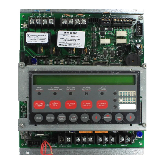
Front panel
Hide thumbs
Also See for 4010:
- Applications manual (85 pages) ,
- Service manual (72 pages) ,
- User manual (9 pages)

Subscribe to Our Youtube Channel
Related Manuals for Simplex 4010


Summary of Contents for Simplex 4010
-
Page 1: Fire Alarm
4010 Fire Alarm Front Panel Installing, Operating, and Programming Instructions 574-052 Rev. F Technical Manuals Online! - http://www.tech-man.com... - Page 2 This page intentionally blank Technical Manuals Online! - http://www.tech-man.com...
- Page 3 Alarm Control Panel (FACP) operation and reliability depend upon proper installation. DO NOT INSTALL ANY SIMPLEX PRODUCT THAT APPEARS DAMAGED. Upon unpacking your Simplex product, inspect the contents of the carton for shipping damage. If damage is apparent, immediately file a claim with the carrier and notify Simplex.
- Page 4 This page intentionally blank. Technical Manuals Online! - http://www.tech-man.com...
- Page 5 Requires 4010-9809 City Circuit Module • Remote Station - protected premise (formerly NFPA 72C) Requires 4010-9809 City Circuit Module or the 4010-9810 or -9816 DACT • Proprietary - protected premise (formerly NFPA 72D) Requires 4010-9817 (with 4010-9818 or 4010-9819) or 4010-9821 Network Interface Modules •...
- Page 6 The installer should be familiar with the relevant codes listed below as well as Codes and Standards any other applicable local codes and standards, when installing a fire alarm (continued) system. • NFPA 72 National Fire Alarm Code • NFPA 11 Standard for Low-Expansion Foam and Combined Agent Systems •...
-
Page 7: Table Of Contents
Table of Contents Chapter 1. 4010 FACP Overview Introduction....................1-1 In this Chapter................... 1-1 Related Documentation................. 1-2 Base System Module..................1-3 Overview....................1-3 SFI/O......................1-3 Power Supply – Base System..............1-4 Default Settings..................1-4 Environmental Specifications ..............1-4 Optional System Modules ................1-5 Overview.................... - Page 8 Chapter 3. Wiring Overview....................3-1 In this Chapter................... 3-1 Overview....................... 3-2 Power Limited Versus Non-Power Limited Systems ........ 3-2 Locations of Terminal Connections ............3-3 NAC Wiring....................3-4 Overview....................3-4 Terminal Connections ................3-4 IDNet Wiring ....................3-5 Overview....................3-5 Terminal Connections ................
- Page 9 Chapter 5. Configuring Cards Overview....................5-1 In this Chapter................... 5-1 Card Addresses ..................... 5-2 Card Addresses ..................5-2 Adding, Deleting, or Modifying 4010 Cards ..........5-3 Overview....................5-3 Adding a Card ................... 5-3 Deleting a Card ..................5-4 Modifying a Card ..................5-5 Chapter 6.
- Page 10 Chapter 7. System Options Overview....................7-1 In this Chapter................... 7-1 System Options Menu ................... 7-2 Introduction....................7-2 Time/Date Format..................7-3 Overview....................7-3 Setting the Time Format................7-3 Active Status Reminder................. 7-4 Overview....................7-4 Setting the Active Status Reminder............7-4 Silence/Reset Inhibit ..................7-5 Overview....................
- Page 11 Suppression Release..................7-16 Overview....................7-16 Example ....................7-16 Step 1. Turn ON Suppression Release ........... 7-17 Step 2. Assign Suppression Monitor Point Types to Suppression Release Monitor Points.............. 7-17 Step 3. Create Suppression Release Monitor Lists......... 7-17 Step 4. Assign Point Types to Suppression Outputs ......7-18 Step 5.
- Page 12 Chapter 10. Diagnostics and Troubleshooting Overview....................10-1 Before Calling Tech Support ..............10-1 Diagnostics....................10-2 Overview....................10-2 Running Diagnostics ................10-2 Diagnostic Options.................. 10-3 N2 Comm Diagnostics ................10-3 IDNet Diagnostics................... 10-3 IDNet Earth Fault Search Diagnostics ............ 10-4 Network Diagnostics................10-4 Walk Test....................
- Page 13 24I/O Card Status Points................ B-11 24I/O Points ................... B-12 LCD Card....................B-12 LCD Card Status Points ................. B-12 LCD Points .................... B-13 Pseudo Points..................... B-14 Introduction.................... B-14 Digital Pseudo Points................B-14 4010 System Digital Pseudos..............B-15 Technical Manuals Online! - http://www.tech-man.com...
- Page 14 4010 User Digital Pseudos..............B-17 Analog Pseudo Points ................B-18 4010 System Analog Pseudos ..............B-18 4010 User Analog Pseudos ..............B-18 List Pseudo Points.................. B-19 4010 System Lists .................. B-19 4010 User Lists ..................B-20 Appendix C. Glossary of Terms Overview....................C-1...
-
Page 15: Introduction
Chapter 1 4010 FACP Overview Introduction The 4010 is a single-channel, addressable, modular Fire Alarm Control Panel (FACP) that monitors and controls up to 250 IDNet addressable devices. The Standard Function Input/Output (SFI/O) card, power supply, and cabinet provide a complete fire alarm control panel for most applications. Optional modules mount to the chassis to provide additional inputs and outputs, network communication, and additional power. -
Page 16: Related Documentation
4010-9809 City Circuit Card - Installation Instructions 574-056 4010 Fire Alarm Expansion Power Supplies Installation 574-057 Instructions 4010 Fire Alarm RS232 Interface and Service Modem Cards 574-058 Installation Instructions 4010-9820 Battery Meter Module - Installation Instructions 574-165 4010-9814 Suppression Kit - Installation Instructions... -
Page 17: Base System Module
Base System Module Overview The 4010 Base System includes the SFI/O card, power supply, and cabinet. SFI/O The SFI/O contains all connections for optional modules as well as N2 annunciator communication, IDNet, NAC, Auxiliary Power, Auxiliary Relay, PC Programmer (service port), and expansion power connections. -
Page 18: Power Supply - Base System
Important: You must set all cards to the same baud rate in order for the 4010 to operate properly. If you have a 4010 with a Network or DACT card, you must set the SW2 dip switch to the 9600 baud rate. It is recommended that you use the 19,200 option when uploading/downloading information to a PC. -
Page 19: Optional System Modules
Those instructions and their part numbers are listed in the “Related Documentation” section of this chapter. Refer to the label inside the door of the 4010 for the placement of optional modules. -
Page 20: Optional Modules For Expansion Slots
This module mounts to the right of the city module. Optional Modules for The 4010 has a maximum of two expansion slots available to support the Expansion Slots following cards. -
Page 21: Remote Optional Modules
CPU via N2 communication. The 4010 system can be a node on a 4120 Network, however it has limited functionality. Points on the 4010 may be declared as Public. No points on other nodes may be declared as External to the 4010. Set Host and Remote Download functions are fully supported. -
Page 22: Other Compatible Equipment
4010 when wired according to power-limited guidelines. • The 4010 is compatible with the 4120 network. In order to use the 4010 as a node on the network, you must have 4100 master software must be Rev. 8.01 or higher and GCC/NPU must be Rev. -
Page 23: User Interface
User Interface Overview The user interface of the 4010 system consists of control keys, LEDs, a 2-line by 40-character backlit LCD, and a tone-alert mounted in the control panel. The purposes of the Operator and Menu keys are listed below. -
Page 24: Menu Navigation Key Definitions
(provided that no alarms are present). The display will indicate that a reset is in progress and whether or not a reset completes successfully. Menu Navigation Key The following information defines the menu navigation (round) keys on the 4010 Definitions panel. These keys perform access level dependent functions defined in the “Passcodes, Access Levels, and Logging In and Out”... - Page 25 User Interface, Continued Menu Navigation Key Definitions (continued) Enter <Enter> The <Enter> key is used to confirm selections. When pressed, this key provides Enter additional information about the point shown on the display. In a programming screen, pressing <Enter> indicates that the information on the display is correct and can be entered.
-
Page 26: Passcodes, Access Levels, And Logging In And Out
This section describes logging in and out at specific access levels. Passcodes and Access Levels All operations in the 4010 are protected at a preset level with designated passcodes to access these operations. The table below shows the basic operations and menu choices for specific access levels. The default passcodes are listed for Levels 2 through 4. -
Page 27: Logging In And Out
Service Mode trouble. Note that this trouble can only be cleared by restarting the panel. To Login, perform Steps 1 through 7 on a 4010 that is at the High-Level Status screen (refer to Figure 1-2 for an example of this screen). When moving from one digit to the next, an asterisk (∗) appears in the place of an entered number... -
Page 28: Menu Structure
Menu Structure 1-14... -
Page 29: Chapter 2. Back Box Installation
Chapter 2 Back Box Installation Overview This chapter contains instructions and guidelines for installing the 4010 FACP backbox. In this Chapter This chapter discusses the following topics: Topic See Page # Before You Begin Remove Chassis and Cut Conduit Openings... -
Page 30: Before You Begin
4010 back box for more information). • Enclosure must be level and plumb when installed. Standards and Codes When installing the 4010, you should be familiar with the following standards: • NEC Article 300 Wiring Methods •... -
Page 31: Remove Chassis And Cut Conduit Openings
Remove Chassis and Cut Conduit Openings Overview The 4010 ships from the factory completely assembled in the back box, or as a single piece electronics assembly that is shipped separately from the back box, retainer, and door. The system electronics (SFI/O and power supply) are mounted to a steel chassis. -
Page 32: Mount The Backbox
Frame the opening to accommodate the back box. Fit the back box into the opening. Use wall stud guides to ensure free movement of the door. Using mounting hardware capable of supporting a fully loaded 4010, screw or nail back box to the studs. -
Page 33: Re-Install The Chassis
Re-install the Chassis Procedure Use the following steps to re-install the 4010 chassis containing the SFI/O and power supply into the back box. Insert two mounting screws into the top two mounting holes for the chassis. Tighten the screws leaving a 1/8-inch gap from the seated position. - Page 34 This is blank Technical Manuals Online! - http://www.tech-man.com...
-
Page 35: Overview
Overview This chapter contains instructions and guidelines for wiring the 4010 FACP. This chapter describes how to wire the base 4010 FACP. Use the information in this chapter, the 526-407 and 526-408 labels located on the inside door of the FACP, and the 842-058 Field Wiring Diagram to wire the base panel. -
Page 36: Overview
Overview Power Limited Versus Non- The 4010 system can be wired as either a Power Limited or Non-Power Limited Power Limited Systems system. Adhere to the following guidelines and consult the NEC for specifics. • When installing the 4010 as a Power Limited system, you must observe the following guidelines: Maintain ¼... -
Page 37: Locations Of Terminal Connections
Locations of Terminal Figure 3-2 shows the location of all terminal connections for the system Connections components. Refer to the appropriate section later in this chapter for specific information on wiring a component. 4010-9806 4010-9806 Class A Class A Module... -
Page 38: Nac Wiring
The 4010 provides four NACs for notification appliances such as horns and strobes. These NACs are standard Class B (Style Y). Optional Class A (Style Z) operation can be achieved using an adapter. Refer to the 4010-9806 Class A Module - Installation Instructions, Part No. 574-055 for information on the Class A NAC adapter. -
Page 39: Idnet Wiring
Overview The 4010 uses addressable IDNet devices (smoke and heat detectors/sensors and pull stations, 4009 IDNet NAC Extender, etc.). The 4010 supports 250 devices on a single pair of wires on a single channel. The IDNet channel supports Style 4 and 6 as part of the base system. Refer to the 4010 Field Wiring Diagram (842-058) for all wiring information. -
Page 40: Ac Power And Battery Wiring
AC Power and Battery Wiring AC Power When the 4010 FACP is installed as a Power-Limited system, AC power lines must be run in a separate conduit, and should enter the back box in the lower right corner. Use the shaded area of Figure 3-5 only for routing of AC power wiring. -
Page 41: Installing And Connecting Batteries
AC Power and Battery Wiring, Continued Installing and Connecting The base 4010 FACP accommodates (and charges) up to 25 Ah capacity Batteries batteries. The following is a list of compatible batteries. • 2081-9272, 6.2 Ah • 2081-9274, 10 Ah •... - Page 42 BATTERY BATTERY Figure 3-7. Canadian Battery Wiring WARNING: DO NOT APPLY BATTERY POWER TO THE 4010 AT THIS TIME! DO NOT connect crimped ends of the red and black wires to the battery. Refer to the “Power-Up and Checkout” section of this publication for more information.
-
Page 43: Auxiliary Relays
Use Figure 3-8 to wire the AUX relay circuits. TB6 and TB7 are located at the bottom of the SFI/O near the center. When power for the AUX relay contacts is from TB5 (AUX Power), 4010-9813, or 4010-9814 expansion power supplies, the circuit is power-limited. When power for the AUX relay contacts IS NOT from the sources listed above, use an in-line fuse (Part No. -
Page 44: System Power-Up And Checkout
Caution: Notify fire, central station, and/or building personnel before testing the system. Power-Up After applying power to the system, use the following list to check the 4010 for proper operation. • Check that the green AC Power LED is ON. - Page 45 System Power-Up and Checkout, Continued Power-Up and Checkout If the 4010 passes its start up self-test, the FACP starts and the system is normal, (continued) the High-Level Status screen shown in Figure 3-10 displays. If troubles exist in the system, Figure 3-11 displays after pressing <ACK>.
-
Page 46: Acceptance Test
When finished with the original installation and all modifications, conduct a complete operational test on the entire installation to verify compliance with applicable NFPA standards. Testing should be conducted by a Simplex-trained technical representative in the presence of a representative of the Authority Having Jurisdiction, and the customer’s representative. -
Page 47: Periodic Testing And Maintenance
Periodic Testing and Maintenance Overview Periodic testing and maintenance of the FACP, all initiating and notification devices, and any other associated equipment is essential to ensure proper and reliable operation. Test and maintain the FACP according to the schedules and procedures outlined in the following publications: •... - Page 48 Periodic Testing and Maintenance, Continued Battery Testing Information (continued) Table 3-1. Battery Testing Voltage Amp Hr Resistor Watts Part No. and Description Test Time (Ohms) 380-031 2 Seconds 380-031 (adj to 4.5 Ohm) 2 Seconds 380-031 (adj to 4 Ohm) 2 Seconds 380-031 (3 in parallel) 2 Seconds...
-
Page 49: Chapter 4. Quick Cfig
Overview The Quick CFIG option provides you with the ability to quickly and automatically program the components and features of the 4010. Quick CFIG is especially useful for programming basic system components following a new installation, and for adding components to an existing installation. -
Page 50: Reconfigure All Hardware
Reconfigure ALL Hardware Overview This option starts the 4010 with a new configuration. If a configuration already exists and this option is selected, it clears the current configuration and adds all currently connected devices to the CFIG. Procedure Press <MENU>. -
Page 51: Auto Detect New Hardware
Procedure Press <MENU>. Press <NEXT> or <PREVIOUS> until [Quick CFIG] is displayed and then press <ENTER>. A warning appears, indicating that the 4010 is no longer in the Fire Alarm Operation mode. Please Wait . . . Fire Alarm Operation Suspended Press <ENTER>... -
Page 52: Restore Factory Cfig
Restore Factory CFIG Overview This option restores the 4010 to its original (factory default) CFIG. All pseudo points (Analog and Digital) are cleared, Custom Control is erased, etc. Procedure Press <MENU>. Press <NEXT> or <PREVIOUS> until [Quick CFIG] is displayed and then press <ENTER>. -
Page 53: Accept Default Settings For System Options
Procedure Press <MENU>. Press <NEXT> or <PREVIOUS> until [Quick CFIG] is displayed and then press <ENTER>. A warning appears, indicating that the that the 4010 is no longer in the Fire Alarm Operation mode. Please Wait . . . Fire Alarm Operation Suspended Press <ENTER>... -
Page 54: Edit Settings For System Options
Procedure Press <MENU>. Press <NEXT> or <PREVIOUS> until [Quick CFIG] is displayed and then press <ENTER>. A warning appears, indicating that the 4010 is no longer in the Fire Alarm Operation mode. Please Wait . . . Fire Alarm Operation Suspended Press <ENTER>... - Page 55 Edit Settings for System Options, Continued Procedure (continued) Table 4-1. System Options and Available Settings (continued) System Option Settings Visual NAC Operation Choose: • Visual NACs: Steady • Visual NACs: Slow March • Visual NACs: Fast March • Visual NACs: Temporal •...
-
Page 56: Save Cfig Option
CFIG following the Quick CFIG operation. The Save CFIG option saves all information to the 4010 configuration after or during programming. Choose this option if you wish to save all of your edits and modifications you made during your programming session to the 4010 configuration. -
Page 57: Chapter 5. Configuring Cards
Chapter 5 Configuring Cards Overview The 4010 allows you to manually configure each option card in the system. This chapter describes how to add, delete, or modify optional cards in the 4010 FACP. Note: The system must be powered down before cards are added to the system. -
Page 58: Card Addresses
Card Addresses Card Addresses All card addresses (whether hardware or logical cards) are shown in Table 5-1. Table 5-1. 4010 Card Addresses Card Address Reserved Cards CPU Board NAC/Relay circuits Power Supply IDNet Channel Dual RS232 or Service Modem 5 - 7... -
Page 59: Adding, Deleting, Or Modifying 4010 Cards
Adding, Deleting, or Modifying 4010 Cards Overview This section describes how to add, delete, or modify cards in a 4010 FACP. Be aware of the following configuration rules when adding, deleting, or modifying cards. • Cards 1 through 3 and 17 through 23 cannot be deleted. -
Page 60: Deleting A Card
Continued Adding a Card (continued) When first adding a 24-Point I/O or LCD Annuciator cards to the 4010, you must choose an available address of 9 through 14. (The system automatically picks the next available address.) When selecting 24IO or LCD and then pressing Enter, the following figure appears. -
Page 61: Modifying A Card
Adding, Deleting, or Modifying 4010 Cards, Continued Modifying a Card Use the following steps to Modify a card in the 4010 FACP. The only cards you can modify from this menu are the Dual RS232, Modem/RS232, and LCD Annunciator cards. - Page 62 COMMAND (For use with a CRT on Port B Only) Baud Rates: 1200, 2400, 4800, 9600, 19200, 38400 Parity: NONE, EVEN, ODD Note: To print 4010 reports, you must have an 80-column printer. Modem Card Device: PRT40U (unsupervised 40-Column printer)
-
Page 63: Overview
Overview The 4010 allows you to manually program each point in the system. This chapter describes how to add, delete, edit, etc., points in the 4010 FACP. The following information assumes you have all cards properly installed. If your cards are not installed properly or need modification, refer to “Chapter 5 - Configuring Cards.”... -
Page 64: Configure Points Menu
Configure Points Menu Configuring Points Menu All options for configuring 4010 points are located in the Configure Points menu. Figure 6-1 shows the structure of this menu. Programming Menus Save CFIG Configure Configure Points Cards • TrueAlarm • ZAMs/IAMs/RIAMs •... -
Page 65: Configuring Truealarm Points
This section describes how to Add an IDNet Point, Edit a TrueAlarm Point, and Delete a TrueAlarm Point. Add IDNet Point Use the following steps to Add an IDNet point to the 4010 FACP. Press <MENU>. Press <NEXT> or <PREVIOUS> until [PROGRAMMING] is displayed and then press <ENTER>. -
Page 66: Delete Truealarm Point
2. To complete these functions, refer to their appropriate section in this publication. Delete TrueAlarm Point Use the following steps to delete a TrueAlarm point from the 4010 FACP. Press <MENU>. Press <NEXT> or <PREVIOUS> until [PROGRAMMING] is displayed and then press <ENTER>. A warning appears, indicating that the 4010 is no longer in the Fire Alarm Operation mode. - Page 67 Configuring TrueAlarm Points, Continued Delete TrueAlarm Point Press <NEXT> or <PREVIOUS> until <CONFIGURE POINTS> is (continued) displayed and then press <ENTER>. Press <NEXT> or <PREVIOUS> to scroll through your choices until <TRUEALARM> is displayed and then press <ENTER>. Use <NEXT> or <PREVIOUS> to scroll through your choices until <DELETE IDNet POINT>...
-
Page 68: Configuring Zam/Iam/Riam Points
Overview This section describes how to Add, Edit, and Delete an ZAM/IAM/RIAM point. Adding ZAM/IAM/RIAM Point Use the following steps to add a ZAM/IAM/RIAM point to the 4010 FACP. Press <MENU>. Press <NEXT> or <PREVIOUS> until [PROGRAMMING] is displayed and then press <ENTER>. A warning appears, indicating that the 4010 is no longer in the Fire Alarm Operation mode. - Page 69 Configuring ZAM/IAM/RIAM Points, Continued Editing a ZAM/IAM/RIAM Point Use <NEXT> or <PREVIOUS> to scroll through your choices until <Edit (continued) IDNet Point> is displayed and then press Enter. Press <NEXT> or <PREVIOUS> to scroll through your list of ZAM/IAM/RIAM points until the desired point is displayed and then press Enter.
-
Page 70: Deleting Zam/Iam/Riam Idnet Point
Configuring ZAM/IAM/RIAM Points, Continued Deleting ZAM/IAM/RIAM IDNet Use the following steps to delete a ZAM/IAM/RIAM point from the 4010 Point FACP. Press <MENU>. Press <NEXT> or <PREVIOUS> until [PROGRAMMING] is displayed and then press <ENTER>. A warning appears, indicating that the 4010 is no longer in the Fire Alarm Operation mode. -
Page 71: Configuring Relay And Nac Points
SW/LED point. The following assumes that you have chosen Relay, NAC, or User-Defined SW/LED as your option after entering the Configure Points menu. Procedure Use the following steps to configure a Relay or NAC point in the 4010 FACP. Press <MENU>. Press <NEXT> or <PREVIOUS> until [PROGRAMMING] is displayed and then press <ENTER>. - Page 72 Configuring Relay and NAC Points, Continued Procedure (continued) Table 6-3. Relay and NAC Point Configuration Choices Function Description Edit Device Type Changes the Hardware Device Type of the Point (See Note 2) Edit Point Type Changes the Software Point Type of the Point (See Notes 2 and 3) Edit Point Label Changes the 40-Character Label of the Point...
-
Page 73: Configuring Digital And Analog Pseudo Points
4010 FACP. Press <MENU>. Press <NEXT> or <PREVIOUS> until [PROGRAMMING] is displayed and then press <ENTER>. A warning appears, indicating that the 4010 is no longer in the Fire Alarm Operation mode. Please Wait . . . -
Page 74: Configuring Analog Pseudo Points
4010 FACP. Press <MENU>. Press <NEXT> or <PREVIOUS> until [PROGRAMMING] is displayed and then press <ENTER>. A warning appears, indicating that the 4010 is no longer in the Fire Alarm Operation mode. Please Wait . . . - Page 75 Configuring Digital and Analog Pseudo Points, Continued Configuring Analog Pseudo Press <NEXT> or <PREVIOUS> until <CONFIGURE POINTS> is Points (continued) displayed and then press <ENTER>. Press <NEXT> or <PREVIOUS> to scroll through your choices until <ANALOG PSEUDOS> is displayed and then press <ENTER>. Use <NEXT>...
-
Page 76: Configuring 24-Point I/O Points
Configuring 24-Point I/O Points Overview The 4010 allows you to use the 4605 24-Point I/O card to monitor input points (switches) and control output points (Lamps, Tone-alerts, and Relays). Configuring 24-Point Input Use the following steps to configure input points on the 24-Point I/O card. - Page 77 Configuring 24-Point I/O Points, Continued Configuring 24-Point Input Table 6-6. 24-Point Input Points Configuration Choices Points (continued) Function Description Edit Device Type Changes the Hardware Device Type of the Point. Choose Input or Output Edit Point Type Changes the Software Point Type of the Point. Your choices for Input points are: •...
-
Page 78: Configuring 24-Point Output Points
Points Press <MENU>. Press <NEXT> or <PREVIOUS> until [PROGRAMMING] is displayed and then press <ENTER>. A warning appears, indicating that the 4010 is no longer in the Fire Alarm Operation mode. Please Wait . . . Fire Alarm Operation Suspended Press <ENTER>... - Page 79 Configuring 24-Point I/O Points, Continued Configuring 24-Point Output Points (continued) Table 6-7. 24-Point Output Point Configuration Choices Function Description Edit Device Type Changes the Hardware Device Type of the Point. Choose Input or Output Edit Point Type Changes the Software Point Type of the Point. Your choices for Output points are: •...
-
Page 80: Configuring List Points
Overview This section describes how to configure a List. Configure a List Use the following steps to configure a List in the 4010 FACP. Press <MENU>. Press <NEXT> or <PREVIOUS> until [PROGRAMMING] is displayed and then press <ENTER>. A warning appears, indicating that the 4010 is no longer in the Fire Alarm Operation mode. -
Page 81: Add A Point To A List
Continued Add a Point to a List Use the following steps to Add a point to a List on the 4010 FACP. A TrueAlarm point is used as an example in the following steps. After selecting Lists as your option under the Configure Points menu, use <NEXT>... -
Page 82: Delete All Points From A List
Continued Delete ALL Points from a List Use the following steps to Delete ALL points from a List on the 4010 FACP. After selecting Lists as your option under the Configure Points menu, use <NEXT> or <PREVIOUS> to scroll through your lists until the desired list is displayed and then press <FUNCTION>. -
Page 83: Configuring User-Defined Sw/Led
The following assumes that you have chosen User Defined SW/LED as your option after entering the Configure Points menu. Configure a User-Defined Use the following steps to configure a User-Defined Switch or LED in the 4010 Switch or LED FACP. -
Page 84: Edit A Mode Of A User-Defined Sw/Led
This section describes how to edit the mode of a User-Defined SW/LED. Use SW/LED the following steps to edit the mode of a User-Defined Switch or LED in the 4010 FACP. After selecting User Defined SW/LED as your option under the Configure Points menu, press <NEXT> or <PREVIOUS> to scroll through the choices listed below. - Page 85 Configuring User-Defined SW/LED, Continued Edit a Mode of a User-Defined SW/LED (continued) Table 6-10. User-Defined SW/LED Modes User-Defined SW/LED Modes • Switch Modes SMPL • • Fire Ack • Supv. Ack • Trouble Ack • Reset • Silence • LTEST •...
- Page 86 This is blank Technical Manuals Online! - http://www.tech-man.com...
-
Page 87: Overview
Overview This chapter describes how to set system options such as Time/Date Format, Active Status Reminder, etc. These options are custom functions for the 4010. The System Options (shown in Figure 7-1) can also be set from the Quick-CFIG menus. -
Page 88: System Options Menu
System Options Menu Introduction All 4010 system options are accessed via the System Options menu choice, which is located in the Programming menu tree. Figure 7-1 shows the structure of the System Options menu. Programming Menus Configure System Custom Cards... -
Page 89: Time/Date Format
The date is always displayed in the following format and cannot be changed: 27-Aug-97 Day of week, date, month, year The Time format directly affects how time is displayed on the 4010 not only at the high-level status screen but in the Historical Logs. Setting the Time Format Use the following steps to set the Time format on the 4010 FACP. -
Page 90: Active Status Reminder
Overview The Active Status Reminder option allows you to set an interval and duration in which the 4010 reminds operators of the FACP that a FIRE, SUPV, or TBL condition still exists in the panel. Your choices are as follows: •... -
Page 91: Silence/Reset Inhibit
Silence/Reset Inhibit Overview You can inhibit the Alarm Silence/System Reset on a 4010 FACP for a set duration. The range for the Silence/Reset Inhibit timer is 0-60 minutes with zero (No Inhibit) being the default setting. Setting the Silence/Reset Use the following steps to set the Silence/Reset Inhibit timer on the 4010 FACP. -
Page 92: Alarm Cut-Out Timer
No Cutout (meaning a manual Alarm Silence is required to shut off signals). Setting the Alarm Cut-Out Use the following steps to set the Alarm Signal Cut-Out timer on the 4010 Timer FACP. Press <MENU>. -
Page 93: Door Drop On Alarm
Door Drop on Alarm Overview The Door Holder - Alarm Door Drop Timer allows the 4010 to hold doors open for a set duration during an alarm condition. After that duration has expired, the 4010 shuts off the door holder relays and the doors close. The range for the timer is 0-60 seconds with a default setting of zero seconds. -
Page 94: Door Drop On Ac Loss
Door Drop on AC Loss Overview The Door Holder - AC Fail Door Drop Timer allows the 4010 to hold doors open for a set duration during an AC power loss condition. After that duration has expired, the 4010 shuts off the door holder devices and the doors close. The range for the timer is 0-60 minutes, with a default setting of 5 minutes. -
Page 95: Audible And Visible Nac Operation
4010 FACP. Press <MENU>. Press <NEXT> or <PREVIOUS> until [PROGRAMMING] is displayed and then press <ENTER>. A warning appears, indicating that the 4010 is no longer in the Fire Alarm Operation mode. Press <ENTER> to continue. Press <NEXT> or <PREVIOUS> until <SYSTEM OPTIONS> is displayed and then press <ENTER>. -
Page 96: Truealert Non-Addressable Horn Operation
Addressable Horn Option Press <MENU>. Press <NEXT> or <PREVIOUS> until [PROGRAMMING] is displayed and then press <ENTER>. A warning appears, indicating that the 4010 is no longer in the Fire Alarm Operation mode. Press <ENTER> to continue. Press <NEXT> or <PREVIOUS> until <SYSTEM OPTIONS> is displayed and then press <ENTER>. -
Page 97: Depleted Battery Cut-Out
Depleted Battery Cut-Out Overview This option selects the mode of operation for the 4010 FACP if an alarm occurs during an AC power loss while a Depleted Battery trouble exists. The specific operation of this option differs slightly, depending on whether you have a domestic or Canadian system. -
Page 98: Stagger Start Ahus
Stagger Start AHUs Overview This option allows you to set the 4010 to stagger start any Air Handling Units (AHUs) control points (point types AHUR, AHUO, and AHUF) in the 4010 FACP . This option protects against power spikes that may cause the circuit breakers to trip when AHUs start simultaneously. -
Page 99: Enable City Circuit
You must enable the City Circuit via the 4010 System Options menu when installing the city circuit card. The default setting for the city circuit is OFF. Setting the Enable City Circuit Use the following steps to set the Enable City Circuit option on the 4010 FACP. Option Press <MENU>. -
Page 100: Expansion Power
You must enable the Expansion Power Supply via the 4010 System Options menu when installing the expansion power supply. The default setting for the expansion power supply is OFF. Setting the Expansion Power Use the following steps to set the Expansion Power Supply option on the 4010 Option FACP. Press <MENU>. -
Page 101: Single-Station
• Alarm remains at panel until reset is performed. Enabling Single-Station Use the following steps to set the Single-Station option on the 4010 FACP. The default setting for this option is ON. Press <MENU>. Press <NEXT> or <PREVIOUS> until [PROGRAMMING] is displayed and then press <ENTER>. -
Page 102: Suppression Release
Suppression Release Overview In order for the Suppression Release function of the 4010 to work correctly you must follow certain steps. Step Description Assign the appropriate point types to your Suppression Release monitoring devices. Add the points in Step 1 to the appropriate Suppression Release lists. -
Page 103: Step 1. Turn On Suppression Release
Suppression Release, Continued Step 1. Turn ON Suppression Press <MENU>, followed by <NEXT> until Programming is displayed. Release Press <ENTER> in response to the prompts to access the Programming menu. 2. Use the <NEXT> button to move through the Programming menu options. Press <ENTER>... -
Page 104: Step 4. Assign Point Types To Suppression Outputs
Press Exit/Clear until the Restore CFIG / Save CFIG options are displayed. Press the arrow to move the focus brackets to Save CFIG and press Enter. Follow the prompts to confirm this action. The 4010 now restarts and saves all programming information to the configuration. 7-18... -
Page 105: Chapter 8. Custom Control
Chapter 8 Custom Control Introduction This chapter provides an overview of the Simplex Multi-functional Programming Language (SMPL), which is also known as Custom Control (both terms are equivalents and are used interchangeably throughout this publication). In this Chapter This chapter discusses the following topics:... -
Page 106: Overview
SMPL programming is programmed through the front panel interface or from the PC Programmer tool. The 4010 base panel is configured (and shipped) as a general alarm system. You must program the Custom Control option when more sophisticated operations are required. -
Page 107: Smpl Opcodes And Operators
SMPL Opcodes and Operators Input Opcodes The following is a list of valid Input Opcodes, Input Operators, and Relational Operators for the 4010 Custom Control option. Table 8-1. Input Opcodes Input Opcodes Description FIRE DETECT Fire Detect State FIRE Fire State... -
Page 108: Input And Relational Operators
SMPL Opcodes and Operators, Continued Input and Relational Table 8-2 lists the Input and Relational Operators. Operators Table 8-2. Input and Relational Operators • Input Operators • • • SAVE • RECALL • DELAY (Constant and Variable) • CYCLE (Constant and Variable) •... -
Page 109: Output Opcodes
SMPL Opcodes and Operators, Continued Output Opcodes Table 8-3 lists Output Opcodes for the 4010 Custom Control option. Table 8-3. Output Opcodes Output Opcodes Description SET ON Set Point ON (refreshes continuously) SET OFF Set Point OFF (refreshes continuously) SET PRI Set Point’s priority (refreshes continuously) -
Page 110: Custom Control Equation
Custom Control Equation Custom Control Example The following is an example of a valid Custom Control equation. FIRE DET 03-01 Input Statement 1 (Fire Detect state of M1-1 : IDNet Device: M1-1) Input Opcode FIRE DET 03-02 Input Statement 2 (or the Fire Detect state of M1-2 : IDNet Device: M1-2) Input Operator FIRE DET... -
Page 111: Custom Control Programming
From the High-Level Status screen, press <MENU>. Press <NEXT> or <PREVIOUS> until [Programming] is displayed and then press <ENTER>. Figure 8-1 appears briefly to warn you that the 4010 is no longer in the Fire Alarm Operation mode. Please Wait. . . -
Page 112: Custom Control Menu Navigation
Custom Control Programming, Continued Custom Control Menu Using <Next> and <Previous>, you can scroll through all the existing equations Navigation of the Custom Control program. Note: All insertions are done above the current location. If you wish to create a new equation before the first equation in the program, press <Next>... -
Page 113: Equation Level
Custom Control Programming, Continued Equation Level You enter the equation level by selecting an existing equation to edit or you elect to Insert a new equation. When creating a new equation, you are shown an empty equation with the active indicator (signified by a leading asterisk [∗]) on the End of Input marker (remember all inserts go above the current focus). -
Page 114: Equations
Continued Equations Version 2.01 or later of the 4010 system supports up to 60 Custom Control equations. A Custom Control equation consists of up to six statements. Each equation consists of two sides: an INPUT SIDE and an OUTPUT SIDE. An equation can be better understood as an “IF/THEN”... -
Page 115: Field 2
Custom Control Programming, Continued Field 1 (continued) The AND Link operator links the current statement in Series with all previous statements in an equation (see Figure 8-6). Field 1 Field 2 Field 3 Field 4 FIRST [FIRE] [3-01] STATEMENT SECOND [AND] [ [FIRE] [3-02]... - Page 116 Custom Control Programming, Continued Field 1 (continued) The OR Link operator links the current statement in Parallel with all previous statements in an equation (see Figure 8-8). Field 1 Field 2 Field 3 Field 4 FIRST STATEMENT [FIRE] [3-01] SECOND [OR] [FIRE] [3-02]...
- Page 117 Custom Control Programming, Continued Field 1 (continued) AND (first) & OR (second) In Figure 8-10 the first and second statements are linked in Series and the third statement is linked in Parallel with the first and second statements. Remember, a Link operator links that statement with all previous statements, not just the statement before it.
- Page 118 Custom Control Programming, Continued Field 1 (continued) OR (first) & AND (second) In Figure 8-12 the first and second statements are linked in Parallel and the third statement is linked in Series with the first and second statements. Remember, a Link operator links that statement with all previous statements, not just the statement before it.
- Page 119 Custom Control Programming, Continued Field 2 Field 2 can be empty or contain the negative operator NOT. NOT is used in Figure 8-14 to state IF point 3-01 is NOT in a FIRE condition, THEN that statement is true. AND & NOT The AND Link operator links the current statement in Series with all previous statements in an equation (see Figure 8-14).
- Page 120 Custom Control Programming, Continued Field 2 (continued) OR & NOT The OR Link operator links the current statement in Parallel with all previous statements in an equation (see Figure 8-16). Field 1 Field 2 Field 3 Field 4 FIRST [FIRE] [3-01] STATEMENT SECOND...
-
Page 121: Fields 3 & 4
STATEMENT Figure 8-19 Example: The condition of 3-01 is FIRE. The 4010 is reset from the Fire Alarm Control Panel (FACP). After the system is reset (and there are no alarms) the condition of 3-02 is FIRE. The appropriate notification appliances now activate for the FIRE condition of 3-02. - Page 122 Continued Fields 3 & 4 (Continued) When the condition of 3-01 is FIRE DET, the input is true for one 4010 polling cycle which can vary depending upon your application, and the output is executed. If the condition of 3-02 becomes FIRE DET after 3-01, the system re- executes the output.
- Page 123 Custom Control Programming, Continued Fields 3 & 4 (Continued) SUPV When using the input condition qualifier SUPV (Supervisory), a statement is true when the point indicated in Field 4 is activated. Field 4 Choices for the SUPV qualifier are: • System Card Points •...
- Page 124 Custom Control Programming, Continued Fields 3 & 4 (Continued) When using the input condition qualifier TBL (Trouble), a statement is true when the point indicated in Field 4 is in trouble. Field 4 choices for the TBL qualifier are: • CPU Card Points •...
- Page 125 Custom Control Programming, Continued Fields 3 & 4 (Continued) ON/CODE and OFF When using the input condition qualifier ON/CODE (On Coding), a statement is true when the point indicated in Field 4 is On or Coding. Field 4 choices for the ON/CODE qualifier are: •...
- Page 126 Custom Control Programming, Continued Fields 3 & 4 (Continued) COMP CNST, ANY, ALL, & DELAY CNST The COMP CNST (Compare Constant) ANY, ALL, and DELAY CNST input condition qualifiers are two-stage qualifiers. Additional programming is necessary in order for these qualifiers to work correctly. When selecting these qualifiers, you must press Enter to program the second stage.
- Page 127 Custom Control Programming, Continued Fields 3 & 4 (Continued) When using the input condition qualifier ANY, a statement is true when the specified number of points from Field B equals the number of points in the List identified in Field D that are in the condition specified by Field C. The choices for Fields B, C, and D are as follows: •...
-
Page 128: Output Side (Then)
Custom Control Programming, Continued Fields 3 & 4 (Continued) Field C Field A Field B SECOND [ALL] [FIRE ACK] [23-01] STAGE FIELDS Two-stage Input List Point Condition Condition Specifier Figure 8-30 Example: When all points in List 23-01 are in the condition of FIRE ACK, then execute the output. - Page 129 Custom Control Programming, Continued Output Side (THEN) (Continued) FIELD 1 Field 1 contains the Action Operators listed in Table 8-3. FIELD 2 When using any action operator, Field 2 choices are: • CPU Card Points • System Card Points • Power Supply Points •...
-
Page 130: Application-Specific Examples
Application-Specific Examples Introduction The following examples detail the use of the 4010’s newer Custom Control features. Day Night Programming M1-1 is a TrueAlarm Photo sensor. Customer wants normal 2.5% sensitivity Example during working hours (7am – 6pm) and higher sensitivity (1.0%) at night. (A11 is current hour analog pseudo point.) -
Page 131: Ahj City Circuit Reset Operation Example
Application-Specific Examples, Continued AHJ City Circuit Reset This example shows how to program the panel or AHJ City Reset operation. Operation Example OUT: HOLD PRI=9,9 END: 8-27 Technical Manuals Online! - http://www.tech-man.com... - Page 132 This is blank Technical Manuals Online! - http://www.tech-man.com...
-
Page 133: Chapter 9. Saving A Cfig
Chapter 9 Saving a CFIG Introduction The 4010 FACP provides the ability to continue making edits, save or discard changes that you make to the panel’s programming. In this Chapter This chapter discusses the following topics: Topic See Page #... -
Page 134: Viewing Cfig Properties
CFIG properties include information such as the System Revision, the job name and its revision, and the system’s current time and date. Procedure The Software Revision menu allows access to the CFIG properties. It is located at the topmost level of the 4010 menu structure. Software Historical Diagnostics... -
Page 135: Continue, Restore Cfig, And Save Cfig
You can restore a CFIG by choosing the menu option as described below or by pressing Exit/Clear to back out of Programming mode and then choosing the Restore CFIG option from the 4010 prompts. In both cases, your 4010 re-boots and becomes operational as a fire alarm system. - Page 136 This is blank Technical Manuals Online! - http://www.tech-man.com...
-
Page 137: Chapter 10. Diagnostics And Troubleshooting
Note: An accurate time and date are essential for the proper operation of the 4010 FACP. Make sure to check the time and date at least once a month, and reset it if necessary. Changing the time and date are described in Chapter 11 of this manual. -
Page 138: Diagnostics
Running diagnostics is the easiest way to ensure proper communication between the FACP and its various devices. To use the Diagnostics, you must be logged in at a Level 4. Follow Steps 1 through 3 to run diagnostics on the 4010. From the High-Level Status screen, press <MENU>. -
Page 139: Diagnostic Options
Diagnostic screen. This screen informs you of the amount of messages sent, the amount of message retries and the amount of card failures. Note that these tallies are only kept while diagnostics are active. Card Address 4010 Card 1, 4010 NAC/Relay Card Msgs Sent=0 Retries=0 Fails=0 Test Message Counts Figure 10-2. -
Page 140: Idnet Earth Fault Search Diagnostics
Diagnostics panel and the first IDNet isolator device or to another isolator device. Note that the 4010 FACP does not function as a fire panel for the duration of an Earth Fault search. If an “earth” cannot be isolated or there are no isolators configured on the system, the 4010 returns a “Unable to Isolate Earth Fault”... - Page 141 Attendance information shows if the network nodes are configured. Each (continued) position on the 4010’s LCD represents a node’s address for a maximum of 80 nodes (only 80 nodes can be displayed because there are only 80 positions on the 2 by 40 character LCD).
-
Page 142: Walk Test
Walk Test Overview Walk Test allows one person to test the functionality of the 4010. Once the panel is placed into Walk Test mode, any device can be tested in any order. For each device, you should simulate both an alarm and trouble. If an audible or visible indication is used, wait for the indication before moving on to the next device. - Page 143 Walk Test, Continued Using Walk Test (continued) The Walk Test options are shown in Figure 10-5. Top Level Menus Set Time Walk Test TrueTest and Date • On/Off • Log/NoLog • Silent/Signal Figure 10-5. Walk Test Options Figure 10-6 shows an example of the Walk Test screen with the default values. Focus Brackets <ENTER>...
-
Page 144: Truetest
TrueTest Overview The TrueTest feature provides a simple method of testing the application specific software in the FACP without the need to manually activate the initiating device circuits. In other words, TrueTest provides an easy method of testing the Input/Output programming to verify that the programming is written as the customer specified. -
Page 145: Using Truetest
TrueTest, Continued Using TrueTest Use Steps 1 through 5 and Figures 10-7 and 10-8 to activate TrueTest. From the High-Level Status screen, press <MENU>. Press <NEXT> or <PREVIOUS> until [TrueTest] is displayed and then press <ENTER>. Press <ì> or <ö> to move the focus brackets to the desired option. Press <NEXT>... -
Page 146: Crash Codes
ROM Memory Fail ROM memory failed its CRC check, either BOOT or Reload application Application. Replace Hardware OS Initialization The 4010 Application failed trying to define an OS Reload application Fail object. Replace Hardware Unexpected An interrupt vector was executed when that interrupt was... - Page 147 Crash Codes, Continued Table 10-3. Crash Codes (continued) Code Meaning Cause Corrective Action Bad Card State The state index for a card was invalid for the card’s type Reload BIN File Failed Restoring Not Used. Erroneous call to the crash handler SMPL Unable to Restore The flash chip copy to RAM function returned an error...
- Page 148 Crash Codes, Continued Table 10-3. Crash Codes (continued) Code Meaning Cause Corrective Action Network Buffer The network card local port buffer handler lost a buffer Reload Job / Check Error versions of tools and panel / reload BIN File Bad Mapnet Packet The mapnet card received a packet that failed its Reload Job / Check consistency check.
-
Page 149: Chapter 11. Operation
Operation Overview This chapter describes common tasks that need to be performed following installation and programming of the 4010 FACP. An operator logged into the system at Level 1 can perform all tasks described in this chapter. In this Chapter... -
Page 150: Handling Abnormal Conditions
Device Condition Figure 11-1. Example Abnormal Condition Screens When the 4010 senses an Alarm Condition, the tone-alert sounds at a march time rate, and the FIRE ALARM LED turns ON and flashes, indicating that an alarm condition is present. In addition, the appropriate indications are shown on the display. -
Page 151: Acknowledging An Alarm, Trouble, Or Supervisory Condition
Turning signals, tone alerts, etc. off is known as Alarm Silencing. An important feature to be aware of when silencing alarms on the 4010 is its “re- sound” capability. If, after silencing the signals, the 4010 detects another... -
Page 152: Resetting The System
Handling Abnormal Conditions, Continued Resetting the System The <SYSTEM RESET> key is used to return the system to its normal state after an alarm condition has been cleared. When the <SYSTEM RESET> key is pressed, it causes any latched circuits to reset automatically. Also reset are initiating devices, relays (including the city relay), notification appliances, and all LEDs and indicators which are programmed to reset with the <SYSTEM RESET>... -
Page 153: Viewing And Clearing Historical Logs
Viewing and Clearing Historical Logs Overview This section describes how to view and clear the Historical Logs on the 4010. The 4010 has three logs; Alarm, Supervisory, and Trouble. The logs can be viewed separately, or they can be viewed in chronological sequence as a single Combined log. -
Page 154: Using The Historical Logs
Viewing and Clearing Historical Logs, Continued Using the Historical Logs To view the Historical Logs, follow Steps 1 through 4. From the High-Level Status screen, press <MENU>. Press <NEXT> or <PREVIOUS> until [Historical Logs] is displayed and then press <ENTER>. Press <NEXT>... -
Page 155: Viewing And Controlling Points
Controlling/Viewing Points Use the Steps 1 through 5 and Figure 11-4 to Control/View Points in a 4010. A TrueAlarm device type and point are used as an example in this section. - Page 156 Viewing and Controlling Points, Continued Controlling/Viewing Points The control functions for each point type is listed in Table 11-2. (continued) Table 11-2. Device Type and Control Functions Device Type Control Functions View Functions TrueAlarm Control: View: • • Clear Verification Tally Address •...
-
Page 157: How To Disable/Enable Points
30 seconds that allows you to abort the enabling of that point. How to Disable Points in Use the Steps 1 through 3 to disable/enable points in alarm on a 4010. You must Alarm be logged in at the appropriate level to disable/enable points. -
Page 158: Editing Custom Labels
To Edit a Custom Label of a point, use Steps 1 through 11. As an example, editing the label of a TrueAlarm point is used in the following steps and in Figure 11-5. Once in the Programming Mode, the 4010 is OFF-LINE. Login to the 4010 at the appropriate level. - Page 159 Use <ö> or <ì> to move to the next character in the label. The <Disable/Enable> key overwrites characters with a space. Pick a label that best suits the location of the device. The 4010 provides up to 40 characters per line (including spaces). The available characters are as follows: ...
-
Page 160: User Control Functions
In addition to the pre-defined functions listed above, the 4010 supports two “User-Defined” function keys. The two user-defined key choices in the function menu are “User Defined 1”... - Page 161 Illuminates all LEDs and all LCD segments on the display. Earth Fault Latch Latches intermittent Earth Fault Troubles into the 4010. User Defined Key 1 One of two user-defined function keys. User Defined Key 2 One of two user-defined function keys.
-
Page 162: Setting The Time And Date
Use Steps 1 through 5 and Figures 11-6 to set the time and date. An accurate time and date setting is essential to the proper operation of the 4010 system. The time and date should be checked at least once a month and reset, as described below, if necessary. - Page 163 Device and Point Types Overview Each point in the 4010 has both a hardware device type and a software point type. The hardware device type is determined by the hardware used. This is used to determine what physical states exist for the point. The hardware device type also determines the valid software point types that can be assigned to a point.
- Page 164 Hardware Device Types Overview The 4010 supports IDNet devices as Fire Alarm input and output, as well as four hardwired output points, and two auxiliary relay output points. TrueAlarm Hardware Device Table A-1 lists the TrueAlarm Hardware Device Types available with the 4010 Types FACP.
- Page 165 155°F (68°C) 3.7% 3.7% 1.7% Level 7 155°F (68°C) Monitor Hardware Device Table A-3 lists the Monitor Hardware Device Types for the 4010. Types Table A-3. Monitor Hardware Device Types Device Type Description MAZAM Class A Monitor ZAM (T-sense) MBZAM...
- Page 166 Hardware Device Types, Continued 4009A Hardware Device Types Table A-4 lists the 4009A hardware device types. (Note: Each 4009A is located at “virtual card” address 17.) Table A-4. 4009A Hardware Device Types Device Type Description 4009A Standard 4009A R4009A 4009A with repeater 4009A8 4009A with four-NAC option board R4009A8...
- Page 167 Software Point Types Monitor Point Types Table A-5 lists the monitor point types and their descriptions. Table A-5. Monitor Point Types Point Type Description FIRE Fire alarm (generic) WATER Waterflow switch HEAT Heat detector DUCT Duct detector FLAME Flame detector PULL Pull station - manual SMOKE...
- Page 168 Software Point Types, Continued Signal Point Types Every 4010 has four Notification Appliance (signal) points. The default configuration is SIG1 & SIG2 “on ‘til silence” (point type = SSIGNAL) and SIG3 & SIG4 “on ‘til reset” (point type = RSIGNAL).
- Page 169 Continued Relay Point Types The 4010 includes two AUX relay points configured as AUX1 and AUX2. The default point type settings for AUX1 set as an Alarm relay on until reset (point type = RRELAY) and AUX2 set as a Trouble/Supervisory relay on until clear (point type = TRELAY).
- Page 170 Software Point Types, Continued TrueAlert Non-Addressable TrueAlert Non-Addressable operation for a particular NAC is enabled by Point Types selecting the QALERT software point types. Two types of points exist – one under system control and one with no system mode, which allows you to use Custom Control to perform selective signaling.
- Page 171 Hardware and Pseudo Points Overview This chapter describes the points that may exist in all 4010 systems. The points are broken up into two major groups, hardware points and pseudo points. Furthermore, each of these groups is broken down by card.
-
Page 172: Master Controller Card Status Points
Hardware Points Introduction There are many different types of hardware points that exist in the 4010 system. They include system points that are read only to the user, points on the IDNet channel, points on optional cards, public 4120 network points, and card status points. -
Page 173: Nac Card Status Points
Indicates the status of the LCD backlight on the front panel. NAC Card The NAC (Notification Appliance Circuit) Card is required for all 4010 configurations, and is located at Card Address 1. There are seven hardware points and eight card status points associated with the NAC card. - Page 174 NAC card Signal 4 status and configuration. AUX Circuit: AUX 1 NAC card Relay 1 status and configuration. AUX Circuit: AUX 2 NAC card Relay 2 status and configuration. City Circuit Interface 4010 City Module. Continued on next page Technical Manuals Online! - http://www.tech-man.com...
-
Page 175: Power Supply Card
Hardware Points, Continued Power Supply Card The Power Supply Card is required for all 4010 configurations, and is located at Card Address 2. There are nine hardware points and two card status points associated with the Power Supply card. Power Supply Card Status The Power Card has two card status points associated with it. -
Page 176: Idnet Card
This utility point indicates the status of the battery charger (on/off). IDNet Card The IDNet Card is required for all 4010 configurations, and is located at Card Address 3. The IDNet Card defaults to a configuration with no hardware points (devices). -
Page 177: Idnet Points
Hardware Points, Continued IDNet Card Status Points (continued) Table B-6 Card Status Points for the IDNet Card. Point Label Description 3-CS1 Missing Card This trouble indicates that the IDNet card is not communicating with the master. 3-CS2 Wrong Card This trouble indicates that the card returned a card type as something other than a IDNet card type. -
Page 178: Rs232/Modem Card
Continued RS232/Modem Card Either an RS232 Card or Modem Card may be added to the 4010 system. Even though these cards are optional, if an RS232 or Modem card is configured, it must reside at Card Address 4. There are two hardware points and eight card status points associated with the both the RS232 card and Modem card. -
Page 179: Dact Card
Port B point. Default to command line port. DACT Card The DACT card is an optional card that may be added to the 4010 system. The DACT card is mutually exclusive with the Network card, and if configured, must reside at Card Address 8. There is one hardware point and seven card status points associated with the DACT card. -
Page 180: Network Card
Card Address 8. The network card allows the 4010 to serve as a network node for a 4120 network. Points on the 4010 may be declared public to the 4120 network. These points are the Network Status points, and will be described in this section. -
Page 181: 24I/O Card
511th network public point. 24I/O Card The 4010 can have up to six annunciator cards added to the system. One of these cards is the 24I/O card. The 24I/O card can reside at addresses 9 through 14. There are 24 hardware points and two card status points associated with the 24I/O card. -
Page 182: 24I/O Points
The 24th point on the 24I/O card. LCD Card The 4010 can have up to six annunciator cards added to the system. One of these cards is the LCD card. The LCD card can reside at addresses 9 through 14. There are five hardware points and four card status points associated with the LCD card. -
Page 183: Lcd Points
Hardware Points, Continued LCD Points The LCD card has five hardware points associated with it. Only the first three hardware points (user LEDs) on the LCD card can be programmed by the user. The labels for the points on the LCD card are default labels, and cannot be changed by the user. -
Page 184: Pseudo Points
Pseudo cards contain no card status points. Digital Pseudo Points Every 4010 system has two Digital Pseudo "cards" at addresses 18 and 19. The first card is reserved for system pseudo points while the second is available to the user. Each contains 75 digital pseudo points which may be programmed as shown in Table B-18. -
Page 185: System Digital Pseudos
Continued 4010 System Digital Pseudos The system digital pseudo card in the 4010 system is located at Card Address 18. It contains a total of 75 reserved system pseudo points that cannot be edited. The following table list the system pseudo points. The type field denotes which class (see above) the point falls into, and what its type is (U =UTIL, F=FIRE, T=TROUBLE, S=SUPERVISORY). - Page 186 Pseudo Points, Continued 4010 System Digital Pseudos (continued) Table B-20. System Pseudo Points (Continued) Point Type Label Description RW T City Disconnect On if city circuit is disconnected. City Circuit Trouble On if city circuit is in trouble. AHJ City Reset Utility Point On if city circuit reset is enabled.
-
Page 187: 4010 User Digital Pseudos
Unused. 4010 User Digital Pseudos The user digital pseudo card in the 4010 is at address 19. It has 75 points available for specialized applications programming. Any point may be programmed as one of the four types of digital pseudos (i.e. UTILITY, FIRE, etc.), and each may be assigned a 40 character custom label. -
Page 188: Analog Pseudo Points
Current Hour Current Minute 4010 User Analog Pseudos The user analog pseudo card in the 4010 is at Card Address 21. It has 25 points available for specialized applications programming. The analog user pseudos can have custom labels assigned to them. -
Page 189: List Pseudo Points
Manual Control On/Coding The 4010 restricts the total number of points in any one list to 255. It also restricts the total number of points available on any one list card to 500 (the total number of points in all lists on one list card cannot exceed 500). -
Page 190: 4010 User Lists
Filled by the user. Activated by the panel when the suppression release algorithm completes. The user list pseudo card in the 4010 is at Card Address 23. It has 25 points 4010 User Lists available that may be filled by the user for specialized applications. The user lists may have custom labels assigned to them. -
Page 191: Glossary
Appendix C Glossary of Terms Overview This appendix contains a glossary of common terms used throughout the manual. Glossary Alarm - A warning of fire danger. Alarm Signal - A signal indicating an emergency requiring immediate action, such as a signal indicative of fire. Alarm Verification - A feature to reduce unwanted alarms wherein smoke detectors must report alarm conditions for a minimum period of time, or confirm alarm conditions within a given time period, after being reset to be accepted as a... - Page 192 Hardware Device Type - The Hardware Device Type is assigned to each point in an 4010 system. The Hardware Device was formerly known as Device Type. Valid Hardware Device Types include the Addressable Detector Base, Line Powered IAM, TrueAlarm Photoelectric Detector and other types of hardware that are assigned as points in the system.
- Page 193 Municipal Master Box - An initiating device intended to send an alarm condition to the public fire service communications center. N2 COMMS - The communications protocol used by the 4010 to communicate from the CPU to “slaves” in the system.
- Page 194 Glossary (continued) Software Point Type - The software point type assigned to each hardware device in the system defines the software operation associated with that hardware device. This was formerly referred to as “point type.” The software point type assigned to each hardware device defines status reporting, including the default point banner that is displayed, printed or logged upon point status changes.
-
Page 195: Index
Index set/reset priorities. see priority to start custom control programming, 8-7 custom labels editing, 11-10 24 point I/O, 1-7 Device Types, A-2 access levels, 1-12 Hardware, A-2 acknowledging (ACK) Monitor Hardware Device Types, A-3 alarms, troubles, supervisories, 11-3 diagnostics, 10-1 active status reminder, 7-4 diagnostic options, 10-3 alarm ack key, 1-9... - Page 196 how to reset the system, 11-4 restore CFIG, 9-3 menu key, 1-10 menu structure, 1-14 save CFIG, 9-3 Saving a CFIG, 9-1 NAC operation SFI/O, 1-3 audible, 7-9 silence/reset inhibit option, 7-5 visible, 7-9 silencing alarms, 11-3 network. see diagnostics, network diagnostics single-station non-power limited wiring, 3-2 setting the single station option, 7-15...
- Page 197 INSIDE BACK COVER Technical Manuals Online! - http://www.tech-man.com...
- Page 198 Rev. F 574-052 Simplex Time Recorder Co., Westminster, Massachusetts 01441-0001 U.S.A. Technical Manuals Online! - http://www.tech-man.com Simplex International Time Equipment, Co., LTD. • Mississauga, Ontario, Canada...
Need help?
Do you have a question about the 4010 and is the answer not in the manual?
Questions and answers
On a 4010 what is point label 4009A trouble. I **** not familiar with this
A point label trouble on a Simplex 4010 related to a 4009A booster may indicate that the point assigned to the booster is not properly configured or is experiencing communication issues. This could be due to incorrect dip switch settings, wiring issues, or the point type not being correctly set in the system configuration. All 4009 NACs are automatically set for Class B operation and assigned a point type of SSIGNAL, but manual programming may be needed if Quick CFIG does not resolve the issue.
This answer is automatically generated