Simplex 4010ES IDNAC Installation Manual
Fire alarm system
Hide thumbs
Also See for 4010ES IDNAC:
- Installation manual (110 pages) ,
- Operator's manual (58 pages) ,
- Installation instructions manual (26 pages)
Table of Contents
Advertisement
Quick Links
Advertisement
Table of Contents

Related Manuals for Simplex 4010ES IDNAC


Summary of Contents for Simplex 4010ES IDNAC
- Page 1 4010ES IDNAC Fire Alarm System Installation Guide 579-1150 Rev M *05791150M*...
- Page 2 This page is intentionally blank...
-
Page 3: Table Of Contents
1 Cautions, Warnings, and Regulatory Information.................... 3 2 Overview................................4 2.1 Standalone configuration....................................4 2.1.1 Standalone system layout......................................5 2.2 Network configuration....................................6 2.2.1 Connecting network loops (4120 network only)..............................7 2.2.2 ES Net Network configurations....................................7 2.2.3 4120 Network communication....................................9 2.2.4 ES Net network communication....................................9 3 Basic hardware.............................. - Page 4 11.1.1 Procedure............................................ 75 11.2 Alarm Cutout Timer....................................75 11.2.1 Enabling Alarm Cutout Timer....................................76 11.3 Non-Steady Visual Evacuation system option............................76 12 Appendix C: Simplex special application appliances and accessories............78 13 Appendix D: IDNAC compatible appliances....................79 page ii 579-1150 Rev M...
-
Page 5: Cautions, Warnings, And Regulatory Information
Product operation and reliability depend upon proper installation. DO NOT INSTALL ANY SIMPLEX™ PRODUCT THAT APPEARS DAMAGED Upon unpacking your Simplex product, inspect the contents of the carton for shipping damage. If damage is apparent, immediately file a claim with the carrier and notify an authorized Simplex product supplier. -
Page 6: Overview
4010ES IDNAC Fire Alarm System Installation Guide 2 Overview The 4010ES panel is an expandable fire alarm panel that can be used either as a standalone system or can be networked with the following other panels to create a larger network: •... -
Page 7: Standalone System Layout
4010ES IDNAC Fire Alarm System Installation Guide 2.1.1 Standalone system layout Figure 1 shows the layout of the 4010ES standalone configuration. Figure 1: Standalone 4010ES system page 5 579-1150 Rev M... -
Page 8: Network Configuration
4010ES IDNAC Fire Alarm System Installation Guide Network configuration The 4010ES can be expanded to a network system by using the 4010-9902 and the 4010-9922 network interface card (NICs) for a 4120 network or by using the 4010-6310 ES Net Network Interface Cards (NICs) for an ES Net network. When a NIC is installed into a 4010ES host panel, it is used to connect to up to 98 other network nodes. -
Page 9: Connecting Network Loops (4120 Network Only)
4010ES IDNAC Fire Alarm System Installation Guide 2.2.1 Connecting network loops (4120 network only) Network loops can be joined via physical bridge cards. There may be no more than two Class X network loops (two hub configurations) connected in tandem. For every two loops that are interconnected (using one physical bridge), there can be a maximum of three physical bridges used in a star configuration. - Page 10 4010ES IDNAC Fire Alarm System Installation Guide Figure 4: ES Net ring configuration Figure 5: ES Net hub or star configuration Figure 6: ES Net seven node multi-ring network page 8 579-1150 Rev M...
-
Page 11: 4120 Network Communication
4010ES IDNAC Fire Alarm System Installation Guide 2.2.3 4120 Network communication Network communication is achieved via the 4010-9902 and the 4010-9922 NICs. Each network node requires a NIC. Once the FACU is a network node, it may be programmed to be fully in control of other nodes, or to be fully passive, or anywhere in between. -
Page 12: Basic Hardware
• Ethernet Service port - PC connection used by Simplex service personnel. • Serial Service port - Interface for service equipment or Simplex service personnel. • Class A/B Remote Unit Interface - Remote connection to system components not located within 4010ES box. - Page 13 4010ES IDNAC Fire Alarm System Installation Guide Figure 8: Dead front mounted CPU with a 2 x 40 display (back view) page 11 579-1150 Rev M...
-
Page 14: Cpu Leds
4010ES IDNAC Fire Alarm System Installation Guide 3.1.1 CPU LEDs The tables below outline the functions of the LEDs on the CPU card. Table 1: Reset LED Reference designator Silkscreen name Color Status ON = CPU is in reset FLASHING = Board is unable to come out of reset. Possibly... -
Page 15: Cpu Jumper Settings
4010ES IDNAC Fire Alarm System Installation Guide Table 5: Bootloader status LEDs Reference LED7 LED8 LED9 LED10 designator Silkscreen name Color Green Green Green Green On (0.25 s) On (0.25 s) On (0.25 s) On (0.25 s) Bootloader Initialization Off (0.25 s) Off (0.25 s) Off (0.25 s) Off (0.25 s) -
Page 16: Cpu Connectors/Ports/Terminal Block
4010ES IDNAC Fire Alarm System Installation Guide 3.1.4 CPU connectors/ports/terminal block Table 8: Connectors/ports/terminal block Reference Silkscreen name Function designator COMPACT FLASH Used for alternative job/exec storage. KEYPAD MEMBRANE Used to communicate user inputs from the keypad membrane to the CPU card. -
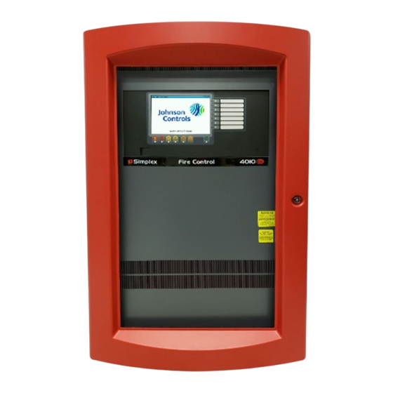
Page 17: Operator Interface
4010ES IDNAC Fire Alarm System Installation Guide Operator interface Shown is the interface for the 4010ES. The operator interface is used to obtain fire alarm, priority 2, supervisory, trouble, and other statuses via the display and LEDs. Control functions are accessed using dedicated and user-programmable keys. -
Page 18: Extended System Supply
4010ES IDNAC Fire Alarm System Installation Guide Extended system supply The ESS is the FACU’s power source and arrives installed in the cabinet. The ESS provides the following: • 24 VDC card power • 6 A of available IDNAC SLC current • Battery charger Note: The 4010ES can hold a maximum of 33 Ah batteries in the one-bay box... -
Page 19: Ess Leds
4010ES IDNAC Fire Alarm System Installation Guide 3.3.1 ESS LEDs The ESS card is equipped with LEDs that help the user diagnose the card and system troubles. Table 11: ESS LED identification and definition LED number Identification Status LED1 IDNet negative earth On = IDNet negative terminal is connected to earth.*... -
Page 20: Ess Jumpers
4010ES IDNAC Fire Alarm System Installation Guide 3.3.2 ESS Jumpers The ESS card is equipped with jumpers that allow the user to configure certain elements of the ESS card. Table 13 explains the jumpers. Table 13: ESS jumper functions Jumper... -
Page 21: Specifications
4010ES IDNAC Fire Alarm System Installation Guide 3.3.3 Specifications Table 14 lists the specifications for the ESS. Table 14: Input and output specifications F to 120 F (0 C to 49 Operating conditions Up to 93% relative humidity at 90 F (32 C), non-condensing. - Page 22 4010ES IDNAC Fire Alarm System Installation Guide Table 16: ESS current specifications Standby conditions* Current (battery 24V) Total current for fully loaded IDNAC and IDNet channels (254 and 250 devices respectively) in 563 mA standby *Additional standby conditions: Auxillary relay activated, power trouble LED on, battery charger off, auxiliary power load = 0 mA.
-
Page 23: 48-Led Module
4010ES IDNAC Fire Alarm System Installation Guide 48-LED Module The 48-LED Module (Figure 13) comes pre-installed inside some base configurations of the 4010ES panel. Each LED can be associated with a point, or group of points. By default, the module is supplied with red LEDs, except for the last column which has yellow LEDs. All of them can be replaced by different color LEDs. -
Page 24: 48-Led Module Specifications
4010ES IDNAC Fire Alarm System Installation Guide 3.4.1 48-LED Module specifications Table 17: 48-LED Module current specifications Standby current Current LED controller circuit 20 mA Add to above for each additional LED that is on 1.89 mA Total current for fully loaded 48-LED Module 111 mA... -
Page 25: Panel Configurations
4010ES IDNAC Fire Alarm System Installation Guide 4 Panel configurations The 4010ES comes in either in a one-bay or a two-bay configuration. Each of these can be ordered in a variety of base systems to satisfy various market needs. One-bay 4010ES Panels The basic components are shipped pre-assembled inside the 4010ES panel. -
Page 26: Optional Modules
4010ES IDNAC Fire Alarm System Installation Guide Figure 16: One-bay 4010ES panel (shown with optional LED module) 4.1.1 Optional modules In addition to the basic modules, optional modules can be installed inside the one-bay 4010ES panels. The types of modules available depend on the panel configuration as well as the accessibility and availability of the power distribution interface (PDI) blocks. - Page 27 4010ES IDNAC Fire Alarm System Installation Guide Table 18: Optional modules Optional modules Description Blocks 4010-9905 and 4010-9926 4120 Network Interface TCP/IP physical Bridge Class B (Note 2) 4010-9906 and 4010-9927 4120 Network Interface TCP/IP physical Bridge Class X (Note 2) 4010-9908 4-Point Flat AUX Relay (2 A)
-
Page 28: Back Box Mechanical Specifications
4010ES IDNAC Fire Alarm System Installation Guide 4.1.2 Back box mechanical specifications Back boxes come shipped with the panel and can only be ordered separately as a service part. Table 19 lists the specifications for the one- bay back boxes. - Page 29 4010ES IDNAC Fire Alarm System Installation Guide Figure 18: Two-bay InfoAlarm dead front page 27 579-1150 Rev M...
- Page 30 4010ES IDNAC Fire Alarm System Installation Guide Figure 19: Two-bay 4010ES Panel with standard user interface page 28 579-1150 Rev M...
-
Page 31: Optional Modules
4010ES IDNAC Fire Alarm System Installation Guide Figure 20: Two-bay 4010ES Panel with InfoAlarm interface 4.2.1 Optional modules The same optional modules can be used with the two-bay panels as with the one-bay panels. For a complete list of optional components, Available panels and devices. -
Page 32: Available Panels And Devices
4010ES IDNAC Fire Alarm System Installation Guide 5 Available panels and devices The following chapter lists the 4010ES panels and optional modules that can be ordered. It also lists the installation manuals that are associated with each optional device. Panels... - Page 33 4010ES IDNAC Fire Alarm System Installation Guide Table 22: Two-bay 4010ES systems Panel language and AC Panel PIDs Panel color Panel components voltage • CPU with a 2 x 40 display and a piezo • Standard operator interface 4010-9621 English 120V •...
-
Page 34: Optional Modules
4010ES IDNAC Fire Alarm System Installation Guide Optional modules 5.2.1 Local optional modules Table 23: Local optional modules installation instructions Installation Description instructions 4010-9818 Network Media Card Wired 579-956 4010-9819 Network Media Card Dual Fiber Optic 579-956 4010-6301 4120 SM-L Duplex Fiber Media... -
Page 35: Remote Devices
4010ES IDNAC Fire Alarm System Installation Guide 5.2.2 Remote devices Table 24: Remote power and notification devices installation instructions Installation Description instructions 4009-9401 4009T TrueAlert Controller 574-762 4081-9306 4100U External Battery Charger 120 V (With Cabinet; Holds 11 Ah Batteries) 579-268 4009-9201 4009A 120 V... -
Page 36: Led Kits For The 48-Led Module
4010ES IDNAC Fire Alarm System Installation Guide 5.2.5 LED kits for the 48-LED module Table 28: LED kits for the 48-LED Module Description 4100-9843 8 Yellow LEDs 4100-9844 8 Green LEDs 4100-9845 8 Red LEDs 4100-9855 8 Blue LEDs page 34... -
Page 37: Installing 4010Es Systems
4010ES IDNAC Fire Alarm System Installation Guide 6 Installing 4010ES systems This chapter describes how to mount the 4010ES back boxes to a wall, and install basic system components into the boxes. Before beginning the installation, review this chapter to get a sense of the types of bays and modules that make up the FACU. -
Page 38: Attaching The Dead Front
4010ES IDNAC Fire Alarm System Installation Guide 6.1.2 Attaching the dead front To attach the 4010ES panel dead fronts containing the operator interface and the 48-LED Module (where applicable), follow the steps below: Align the dead front hinges with the hinge pins on the back box, and slide the door down onto the hinge pins. -
Page 39: Dead Front Grounding Straps
4010ES IDNAC Fire Alarm System Installation Guide 6.1.3 Dead front grounding straps Figure 24: Dead front grounding straps - top Figure 25: Dead front grounding straps - bottom page 37 579-1150 Rev M... -
Page 40: Attaching Doors
General field wiring guidelines Power-limited guidelines For wiring guidelines, see the applicable installation documentation or contact your authorized Simplex Product supplier. Make sure these guidelines are accounted for before wiring for power-limited systems: • Non-power limited field wiring (AC power, batteries, city connection) must be installed and routed in the shaded areas shown in Figure •... - Page 41 4010ES IDNAC Fire Alarm System Installation Guide Figure 27: Field wiring guidelines • Tie the wiring located between bays to the internal wiring troughs, if applicable. • When powering remote units or switching power through relay contacts, power for these circuits must be provided by a power-limited power supply listed for fire-protective signaling use.
-
Page 42: Connecting 4010Es Basic Components
4010ES IDNAC Fire Alarm System Installation Guide Figure 28: The EOL relay Note: The 2098-9739 Relay is used as an example. Other UL Listed 24VDC EOL relays can be used, depending on the application. Connecting 4010ES basic components 6.3.1 Connecting the CPU and the operator interface Note: All the basic components come pre-installed with the system. - Page 43 4010ES IDNAC Fire Alarm System Installation Guide Figure 29: CPU Card rear view Figure 30: Top bay page 41 579-1150 Rev M...
-
Page 44: Connecting The Ess
4010ES IDNAC Fire Alarm System Installation Guide 6.3.2 Connecting the ESS Follow the steps below: Connect the ESS to the ESS (Block C) connector on the Top Bay PDI. Attach the ESS to the back box using metal screws and standoffs. - Page 45 4010ES IDNAC Fire Alarm System Installation Guide Figure 31: ESS Bridge HARN1 connector page 43 579-1150 Rev M...
-
Page 46: Connecting The 48-Led Module
4010ES IDNAC Fire Alarm System Installation Guide 6.3.3 Connecting the 48-LED Module Connect port P1 or P2 of the 48-LED Module card (Figure 32) to either port P9 or P10 of the CPU card (Figure 7). Use the 734-181 4-pin connector harness provided. -
Page 47: Rui Wiring
4010ES IDNAC Fire Alarm System Installation Guide RUI wiring The CPU card’s RUI channel supports the following devices: • 4009T • 4009 TPS • 4602 Series RCU/SCU Annunciators • 4606-9102 Remote LCD Annunciator • 4100-7400 Series Graphic Annunciators • 4100-9400 Series Remote InfoAlarm Command Center Wire from the CPU card’s RUI interface to the RUI terminal block (Figure 33). - Page 48 4010ES IDNAC Fire Alarm System Installation Guide Figure 34: RUI wiring to the host panel Note: Wire size must be between 18 AWG (0.8231 mm ) and 12 AWG (3.309 mm Maximum wiring distance: 2,500 feet (762 m) to device from CPU card.
-
Page 49: Installing The Optional Modules
4010ES IDNAC Fire Alarm System Installation Guide Installing the optional modules Note: Skip this section if no optional modules need to be installed. This page contains the general placement guidelines for the optional modules that can be used with the 4010ES panels. Always consult the individual cards’... -
Page 50: Address Configuration Dip Switch
4010ES IDNAC Fire Alarm System Installation Guide Address configuration DIP switch Addressable cards include a bank of eight DIP switches. From left to right (Figure 36) these switches are designated as SWx-1 through SWx-8. The function of these switches is as follows: •... -
Page 51: Connecting Main System Power
4010ES IDNAC Fire Alarm System Installation Guide Figure 37: Card addresses Connecting main system power The 4010ES panel is shipped with the AC block, the transformer and the rectifier already wired together. You only need to wire the AC block to the main power line. The ground wire on the power line connects to a screw, located on the top right back box (Figure 38). The other wires connect to the AC terminal block, as indicated by the labels (Figure 39). - Page 52 4010ES IDNAC Fire Alarm System Installation Guide Figure 38: Grounding wire Figure 39: AC block labels for AC power connections Note: In 220-240 V panels, the 4010ES requires a true transformer output of 220-240 V. Do not connect two out of phase “hot” wires to create the desired voltage.
-
Page 53: Panel Power-Up Sequence
4010ES IDNAC Fire Alarm System Installation Guide Panel power-up sequence Follow the steps below to power-up the 4010ES panel: Connect the negative (-) connector on the battery. Apply AC power. Connect the positive (+) connector on the battery. page 51... -
Page 54: Ess Field Wiring
Wiring parameters Table 30 identifies the ESS IDNet wiring parameters that must be considered when applying this module. For additional wiring information, see the applicable installation documentation or contact your authorized Simplex Product supplier. Table 29: ESS IDNet wiring capacitance parameters... -
Page 55: Class A Wiring
4010ES IDNAC Fire Alarm System Installation Guide Table 30: IDNet wiring distance limits Class B wiring, total channel wiring Class A/X wiring, total channel wiring parameters parameters, Including T-Taps Channel loading Up to 125 devices 126 to 250 devices Up to 125 devices... -
Page 56: Class B Wiring
4010ES IDNAC Fire Alarm System Installation Guide 7.1.3 Class B wiring Class B wiring requires the configuration jumpers to be set to positions 1-3 and 2-4. Two jumpers must be set for each circuit (refer to Figure 42 for locations). Each of the two IDNet outputs provides short circuit isolation between itself and the others. A short on one output is isolated from the others. -
Page 57: Device Wiring Guidelines
4010ES IDNAC Fire Alarm System Installation Guide 7.2.1 Device wiring guidelines Review the following guidelines for devices before you begin the field wiring. • Only IDNAC appliances and other compatible appliances are allowed on the IDNAC SLCs. See the appendix for a list of compatible appliances. - Page 58 4010ES IDNAC Fire Alarm System Installation Guide Figure 44: UTP wiring limit based on alarm current Figure 45: UTP wiring limit based on communication Table 31: Ohms per 1000 ft Gage Ohms/1000 ft 20 AWG 11.347 18 AWG 7.137 16 AWG 4.488 14 AWG 2.8230...
-
Page 59: Class B Wiring To Devices
4010ES IDNAC Fire Alarm System Installation Guide 7.2.4 Class B wiring to devices To connect the ESS IDNAC terminal block to appliances using Class B wiring: Route the wire from the “+” and the “-” outputs on the IDNAC SLC terminal blocks (TB1, TB2 or TB3) to the appropriate inputs on a peripheral notification appliance. -
Page 60: Ess Aux/Nac Wiring
4010ES IDNAC Fire Alarm System Installation Guide Figure 47: Class B wiring with TrueAlert addressable isolators ESS AUX/NAC wiring AUX/NAC terminal The AUX/NAC terminal block is located on the upper right side of the ESS. Through the ES Panel Programmer, this point can be configured as either a 24V Auxiliary (AUX) power (with Class B support, see... - Page 61 4. If circuit is terminated with a 10k EOLR, at the terminals, remove this resistor before wiring. 5. If wiring is routed outside the building, use of a listed secondary protector is required. Use Simplex 2081- 9028 or 2081-9044. A protector must be installed at each building exit/entrance.
-
Page 62: Ess Auxiliary Relay Wiring Guidelines
4010ES IDNAC Fire Alarm System Installation Guide Note: Output of AUX or NAC is 24V nominal. Minimum voltage is 19.5 @ full load and minimum battery; maximum is 31.5V at light load, high AC line. Aux Loads include 4602-9101 Annunciator, 4100-94xx series Annunciators, 4090 series of IDNet ZAMs and IAMs and any Listed device operating within the output limits of the AUX. -
Page 63: Pc Software Connections
4010ES IDNAC Fire Alarm System Installation Guide 8 PC software connections The service port on the CPU allows the 4010ES panel to connect to a PC running utilities, such as diagnostics, programming, CPU firmware downloading, and channel monitoring. Software modes There are three basic software modes that the service port can be used to connect to: •... -
Page 64: Ethernet Service Port
4010ES IDNAC Fire Alarm System Installation Guide Ethernet service port The Ethernet service port J7 on the CPU card is used to connect the panel to a local PC. See below for the port location. Figure 53: Ethernet service port The Ethernet service port connects to the front panel Ethernet connection through a standard straight (non-crossover) Ethernet patch cable. -
Page 65: System Wiring Checkout And Earth Fault Diagnostics
4010ES IDNAC Fire Alarm System Installation Guide 9 System wiring checkout and earth fault diagnostics This chapter describes how to check system wiring and run the Earth Fault Diagnostics in the panel. Checking system wiring This section contains instructions on how to use a multimeter to check system wiring. -
Page 66: Earth Fault Diagnostics
4010ES IDNAC Fire Alarm System Installation Guide Earth fault diagnostics This section contains instructions on how to use the Earth Fault Search feature of the 4010ES diagnostics menus. The minimum earth fault detection level for the 4010ES is 10 KOhms for all circuits. -
Page 67: Starting The Earth Fault Search
4010ES IDNAC Fire Alarm System Installation Guide CURRENT ACCESS LEVEL = y You can now open the diagnostic menu as described in the next topic. 9.3.2 Starting the Earth Fault Search To start an Earth Fault Search: If necessary, press the Menu button to access the menus. -
Page 68: Search Option C: Last Search Result
4010ES IDNAC Fire Alarm System Installation Guide 9.3.5 Search Option C: Last Search Result This option simply displays the last Earth Fault Search result. If there has been no search since the last system startup, or if the last search was aborted, the panel displays: RESULT NOT AVAILABLE. -
Page 69: No Fault
4010ES IDNAC Fire Alarm System Installation Guide 9.4.4 No Fault If the message in the lower right corner of the LCD reads NO FAULT, it means the IDNet channel search could not locate any earth faults on that channel. 9.4.5 Result Not Available If the message in the lower right corner of the LCD reads RESULT NOT AVAILABLE, it means there is no result to view. -
Page 70: 10 Appendix A: Ulc Programming Requirements
4010ES IDNAC Fire Alarm System Installation Guide 10 Appendix A: ULC programming requirements This appendix discusses the programming operations that must be met to comply with Canadian Underwriter’s Laboratory (ULC) standards. 10.1 Common earth fault ground indicator This application monitors a system pseudo (A112) that counts the number of ground faults that occur on the system. Each time this counter increments (i.e., a ground fault occurs), a yellow LED on the operator interface panel illuminates. -
Page 71: Step 2. Program The Led
4010ES IDNAC Fire Alarm System Installation Guide 10.1.2 Step 2. Program the LED Select one of the multicolor LEDs (0-5-11, 0-5-12, or 0-5-13) to program (Figure 57). Click on the Point Type list box and select LEDYELLOW. Click on the Mode drop-down list box and select ON. -
Page 72: Programming The Address And Mode For Each Led
4010ES IDNAC Fire Alarm System Installation Guide Figure 58: The TagList dialog Select points for the list as follows. Non-Adjacent Points. If the points required for the zone are not adjacent to one another, select the points by holding down the CTRL key and then click the mouse cursor on each point. -
Page 73: Setting Alarm Verification Timer To Canadian Operation
4010ES IDNAC Fire Alarm System Installation Guide Figure 60: The Point Editing tab Do the following for each zone. Click on the line for a red LED. Click on the Mode list box and select the FIRE mode. Click on the Reference Address field and enter the identifier for one of the zone’s list Click on the line for the yellow LED that is paired with the red LED you selected in Step 2a. -
Page 74: Setting Alarm Reset/Inhibit Timer
4010ES IDNAC Fire Alarm System Installation Guide Figure 61: Alarm verification properties: Alarm Verification tab 10.4 Setting Alarm Reset/Inhibit Timer The Alarm Reset/Inhibit Timer system option disables the Alarm Silence and System Reset keys for a user-definable duration that ranges from 1 to 60 minutes. The timer is activated only by the first alarm (i.e., subsequent alarms do not reset the timer). -
Page 75: Alarm Cutout Timer
4010ES IDNAC Fire Alarm System Installation Guide Figure 62: The Panel: System Options tab 10.5 Alarm Cutout Timer The Alarm Cutout Timer allows you to set a duration (up to 10 minutes) that specifies how long signals sound following an alarm. For example, with this option set at two minutes, building signals sound for two minutes and then automatically stop. - Page 76 4010ES IDNAC Fire Alarm System Installation Guide Figure 63: System Options: Setting the Alarm Cutout Timer page 74 579-1150 Rev M...
-
Page 77: 11 Appendix B: Ul Programming Requirements
4010ES IDNAC Fire Alarm System Installation Guide 11 Appendix B: UL Programming Requirements This appendix identifies key UL programming requirements for the 4010ES FACU. 11.1 Setting Alarm Verification to US operation When you select United States operation for the alarm verification feature, the system operates as follows: •... -
Page 78: Enabling Alarm Cutout Timer
4010ES IDNAC Fire Alarm System Installation Guide 11.2.1 Enabling Alarm Cutout Timer To enable the Alarm Cutout Timer, do the following: Click on the Panel tab at the top of the programmer. Click on the System Options tab at the bottom of the programmer. A screen similar to the one shown below appears. - Page 79 4010ES IDNAC Fire Alarm System Installation Guide Figure 66: System Options: Setting Non-Steady Visual Evacuation page 77 579-1150 Rev M...
-
Page 80: Appendix C: Simplex Special Application Appliances And Accessories
4010ES IDNAC Fire Alarm System Installation Guide Appendix C: Simplex special application appliances and accessories The following table lists Simplex special application, NAC-compatible, notification appliances and accessories. Table 35: Miscellaneous Description 4090-9005 Suppression Release Peripheral (SRP) 4090-9006 Suppression Release Peripheral (SRP) w/ENCLOSURE... -
Page 81: 13 Appendix D: Idnac Compatible Appliances
4010ES IDNAC Fire Alarm System Installation Guide 13 Appendix D: IDNAC compatible appliances The following IDNAC appliances are compatible with this FACU. Any device PID listed below also represents the same PID with a [-BA] suffix; that suffix only signifies the place of manufacture. - Page 82 4010ES IDNAC Fire Alarm System Installation Guide Table 38: Visible Only notification appliances TrueAlert ES appliances TrueAlert appliances Model numbers Model numbers 49VO-WWA-A-BA 49VO-WWS-A-BA 49VO-WRF 49VO-WRS 49VO-WWF 49VO-WWS 49VO-WRA-A 49VO-WWA 49VO-WWA-A 49VO-WWQ 49VO-WRA-BA 49VO-WRA 4906-9201 49VO-WRF-BA 49VO-WRQ 4906-9202 49VO-WRQ-BA 49VO-APPLWE 4906-9203...
- Page 83 4010ES IDNAC Fire Alarm System Installation Guide Table 40: Compatible LED addressable appliances TrueAlert ES appliances TrueAlert appliances Addressable appliance description Model numbers Model numbers 59VO-WRF 59VO-WRFAB-BA 59VO-WRF-BA 59VO-WWFAB LED Visible Only Wall Mount 59VO-WWF 59VO-WWFAB-BA 59VO-WWF-BA 59VO-APPLWR 59VO-WRFAB 59VO-APPLWW 59VO-WRFH-BA...
- Page 84 © 2019 Johnson Controls. All rights reserved. All specifications and other information shown were current as of document revision and are subject to change without notice. Additional listings may be applicable, contact your local Simplex® product supplier for the latest status. Listings and approvals under Simplex Time Recorder Co.
Need help?
Do you have a question about the 4010ES IDNAC and is the answer not in the manual?
Questions and answers