Simplex 4010ES Operator's Manual
Hide thumbs
Also See for 4010ES:
- Installation manual (110 pages) ,
- Operator's manual (58 pages) ,
- Installation instructions manual (26 pages)
Table of Contents
Advertisement
Advertisement
Table of Contents

Related Manuals for Simplex 4010ES


Summary of Contents for Simplex 4010ES
- Page 1 4010ES Fire Alarm Operator's Manual 579-969 Rev E *0579969E...
- Page 2 This page is intentionally blank...
-
Page 3: Table Of Contents
System Reset Key......................................13 4.7.2 Disabling a point with a trouble condition............................. 13 Supervisory conditions..........................15 How the 4010ES indicates the presence of a supervisory condition..................15 What acknowledge does................................. 15 Acknowledging supervisory conditions............................16 5.3.1 Globally acknowledging supervisory conditions........................... 16 5.3.2... - Page 4 4010ES Fire Alarm Operator's Manual Setting WalkTest options................................28 Setting options....................................29 TrueNAC Voltage Drop Test................................29 9.4.1 Accessing the TrueNAC Voltage Drop Test............................. 30 9.4.2 Testing all TrueAlert Power Supply’s SLCs.............................. 30 9.4.3 Testing each TrueAlert Power Supply’s SLC............................31 9.4.4...
-
Page 5: Cautions, Warnings, And Regulatory Information
Product operation and reliability depend upon proper installation. DO NOT INSTALL ANY SIMPLEX™ PRODUCT THAT APPEARS DAMAGED Upon unpacking your Simplex product, inspect the contents of the carton for shipping damage. If damage is apparent, immediately file a claim with the carrier and notify an authorized Simplex product supplier. -
Page 6: Basic Concepts And Operations
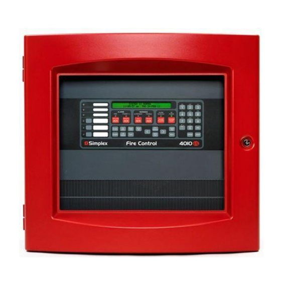
Note: Note: For operation of the 4010ES Panel with an ES Touch Screen Display, refer to 579-1329 This is an overview of the 4010ES operator interface panel and describes the normal appearance of the operator interface panel. The Simplex 4010ES Fire Alarm Control Panel (FACP) has three general functions. -
Page 7: Normal Appearance Of Operator Interface Panel
Normal Appearance of Operator Interface Panel The 4010ES operator interface panel shows the following under normal conditions. • Green power LED is ON - indicating the panel is receiving AC Power • All other LEDs off. -
Page 8: Alarm Conditions
3 Alarm Conditions An alarm condition occurs when an initiating device (such as a manual pull station, smoke detector, etc.) activates. The 4010ES indicates the presence of the alarm condition through messages it displays on the alphanumeric display, by flashing the ALARM indicator, and by activating the building’s notification appliances (horns and strobes). -
Page 9: Individually Acknowledging Alarms
Individually Acknowledging Alarms Use the following procedure if the Individual Acknowledge option is enabled on your 4010ES system. Unlock and open the enclosure door. Read the alphanumeric display on the interface panel. It reports the number of alarm conditions as shown below. -
Page 10: Using The Alarm Silence Key
4010ES Fire Alarm Operator's Manual • If a Coded Input Device (typically a pull station) activates, the ALARM SILENCE key may be ignored until this function has completed coding. Notification appliances (horns) cannot be silenced when a coded station is in alarm, but silence upon coding completion. -
Page 11: Performing A Hardware Reset
Disabling a point that remains in alarm If a device remains in alarm and no alarm condition (i.e., smoke or an activated pull station) exists, the 4010ES provides a way to inhibit alarm reporting for the malfunctioning point. Disabling a point causes a trouble condition for the point or zone that you disable. - Page 12 4010ES Fire Alarm Operator's Manual Note: The system indicates a trouble condition each time a point is disabled. It is important to repair the disabled point as soon as possible. Once repaired, the disabled point should be enabled as soon as possible. See the procedure in Enabling and disabling points.
-
Page 13: Trouble Conditions
How the 4010ES indicates the presence of a trouble When a trouble condition is detected by the 4010ES, the panel does the following to indicate the presence of the trouble condition. • In the Warnings group, the yellow TROUBLE LED flashes. -
Page 14: What To Do When Truealarm Troubles Occur
Globally acknowledging troubles If global acknowledge is enabled on the 4010ES, the system automatically clears after the source of the trouble clears. Approximately 30 seconds after the source of the trouble clears, the alphanumeric display should indicate a normal system. -
Page 15: Individually Acknowledging Troubles
If the trouble doesn’t clear Normally, trouble points do not require acknowledgment of the cleared condition. If the system does not clear, read the display. If the source of the trouble cannot be located, call your Simplex branch office to repair the system. 4.7.1 System Reset Key Some troubles latch until they are reset manually, or are reset by pressing the SYSTEM RESET key. - Page 16 4010ES Fire Alarm Operator's Manual Press the Disable key. The alphanumeric display shows the following message. Press the ENTER key. The alphanumeric display shows the action taken. Note: The system indicates a trouble condition each time a point is disabled. It is important to repair the disabled point as soon as possible.
-
Page 17: Supervisory Conditions
This section describes using the Operator Interface Panel keys to investigate the details of the supervisory condition. How the 4010ES indicates the presence of a supervisory condition When a supervisory condition is detected by the 4010ES, the panel does the following to indicate the presence of the condition. • Yellow LED, labeled SUPERVISORY flashes. -
Page 18: Acknowledging Supervisory Conditions
Read the alphanumeric display. Investigate the problem to determine its cause. Restore or replace the defective device (switch, wire, notification appliance) in accordance with the manufacturer’s instructions, or call Simplex to repair the system. When the problem causing the supervisory is corrected, the supervisory automatically clears and, after a delay, the alphanumeric display indicates that the system status is normal. -
Page 19: Selecting Points For Status And Control
4010ES Fire Alarm Operator's Manual 6 Selecting points for status and control Many of the advanced operations that can be accomplished from the operator interface first require you to select the point on which you want to perform the operation. Points can be selected in one of three ways. -
Page 20: Selecting Points
4010ES Fire Alarm Operator's Manual Figure 4: Entry Keypad 6.3.1 Selecting Points Refer to the following table for information on using the keypad to select local points on this panel. Table 2: Keypad Use Data to Enter ZONE - allows you to select a Monitor Zone point. ZN, followed by ENTER, where ZN represents a zone card and is a number from 1 to n. - Page 21 4010ES Fire Alarm Operator's Manual Table 2: Keypad Use Data to Enter IDNet – allows you to select an IDNet or VESDA C-D, followed by ENTER, where C represents the IDNet, or VESDA channel and D point. represents the device number. You must insert the dash between channel and device.
-
Page 22: Install Mode
4010ES Fire Alarm Operator's Manual 7 Install Mode The Install Mode is a 4010ES feature that allows the user to minimize the amount of Troubles that occur when the system is being installed or when it is undergoing extensive service. -
Page 23: Adding And Removing Groups To Install Mode
4010ES Fire Alarm Operator's Manual Enter the Number of the list you want to move. Press Enter Once the Item appears on the display: - Press 1 to move the List to Install Mode - Press 2 to remove the List from Install Mode. - Page 24 4010ES Fire Alarm Operator's Manual From “View Change Install Mode List” use the arrows to scroll down and select “View the Install Mode List” Press Enter to Display the List of items in Install Mode page 22 579-969 Rev E...
-
Page 25: Advanced Functions
Logging in and out of the system The 4010ES system uses four access levels, referred to by the numbers one through four, to control what system operators can do with the system. The system typically operates at access level one, which allows an operator to accomplish basic tasks (for example, acknowledge alarm, trouble, and supervisory conditions) without logging in to the system. -
Page 26: Log Out Procedure
Setting system time and date Follow these steps to set the time and date used by the 4010ES FACP. Ensuring that the current time and date are correct on the system is important. In particular, the accuracy of historical logs and reports depends on the system time. -
Page 27: Viewing The Time At Which An Event Occurred
4010ES Fire Alarm Operator's Manual a. Time. Use the < and > keys to move the underline character between hours and minutes. Use the Next and Previous keys to increment or decrement the value. For example, to change the minutes, first use the < and > keys to move the highlight under the minutes field. -
Page 28: Displaying And Clearing Historical Logs
4010ES Fire Alarm Operator's Manual Press the AUTOMATIC key. Press the ENTER key to carry out the action. The system clears the Manual Override Trouble. Displaying and clearing historical logs Historical logs provide a record of both the events that have occurred on the system and the actions taken by an operator to manage those events. - Page 29 4010ES Fire Alarm Operator's Manual Table 3: Reports Report Description TrueAlert Status Report This report can be created after the TrueNAC Voltage Drop Test (see TrueNAC Voltage Drop Test) is run. It reports the following information for each Multi Candela TrueAlert Device.
-
Page 30: System Test Procedures
Lamp Test / Tone Alert Test The Lamp Test key on the operator interface panel is used to determine local lamp failures within the system. Lamps on the 4010ES operator interface panel illuminate along with the five function and acknowledge LEDs. -
Page 31: Setting Options
• The line impedance of the SLC channel is determined through the TrueNAC algorithm. • Notification Appliances that fall below the device threshold are reported as failed devices to the 4010ES, and the panel indicates TrueNAC Voltage Drop Test failed trouble. -
Page 32: Accessing The Truenac Voltage Drop Test
• Repeat the TrueNAC Voltage Drop Test. The 4010ES keeps track of the devices that failed the TrueNAC Voltage Drop test. A trouble alarm is indicated on the panel for devices that failed the test. This trouble is cleared after hardware reset. The TrueNAC Voltage Drop Test must be repeated to verify that all troubles are fixed. -
Page 33: Testing Each Truealert Power Supply's Slc
4010ES Fire Alarm Operator's Manual Press the ENTER key on the Entry keypad. If the test is successful, the following message displays. 9.4.3 Testing each TrueAlert Power Supply’s SLC Use the following procedure to test separately each of the TrueAlert Power Supply’s SLC lines. Before you start this test, make sure you have already completed the procedure Accessing the TrueNAC Voltage Drop Test. - Page 34 4010ES Fire Alarm Operator's Manual Example of a failed single-channel test: page 32 579-969 Rev E...
- Page 35 4010ES Fire Alarm Operator's Manual Example of a successful test with an old HW version for TPS 3: page 33 579-969 Rev E...
- Page 36 4010ES Fire Alarm Operator's Manual Example of an aborted (incompatible device problem) test: page 34 579-969 Rev E...
-
Page 37: Disable Idnet Co Algorithms
Disable IDNET CO Algorithms The Disable IDNET CO Algorithms is one of the options available under the Diagnostics menu, at the front panel of the 4010ES. When choosing this option, the technician ensures that the CO sensors will get a testing threshold downloaded and the CO over time is disabled. - Page 38 4010ES Fire Alarm Operator's Manual Figure 6: Testing a single CO sensor page 36 579-969 Rev E...
- Page 39 4010ES Fire Alarm Operator's Manual Figure 7: Simultaneous testing of multiple sensor technologies Disable IDNET CO algorithms without WalkTest enabled With the WalkTest option disabled, the devices will bring in actual alarms at the panel unless specific custom control is written to prevent this.
- Page 40 © 2020 Johnson Controls. All rights reserved. All specifications and other information shown were current as of document revision and are subject to change without notice. Additional listings may be applicable, contact your local Simplex® product supplier for the latest status. Listings and approvals under Simplex Time Recorder Co.
Need help?
Do you have a question about the 4010ES and is the answer not in the manual?
Questions and answers