
Related Manuals for Simplex TrueAlert 4009-9401


Summary of Contents for Simplex TrueAlert 4009-9401
- Page 1 Addressable Controller ™ TrueAlert Installation Guide 574-762 Rev. E firealarmresources.com...
- Page 2 firealarmresources.com...
- Page 3 Tyco Safety Products. Tyco, Simplex, the Simplex logo, IDNet and TrueAlert are trademarks of Tyco International Services AG or its affiliates in the U.S. and/or other countries.
- Page 4 blank firealarmresources.com...
-
Page 5: Table Of Contents
Table of Contents Chapter 1 Introduction to the TrueAlert Addressable Controller ..1-1 Introduction ......................1-1 In this Chapter ......................1-1 Introduction to TrueAlert ....................1-2 Overview........................1-2 The 4009 TrueAlert Addressable Controller..............1-3 Overview........................1-3 Control Types ......................1-5 Overview........................ - Page 6 Mounting and Wiring Peripheral Appliances ............2-16 Installing Option Interfaces ..................2-17 Overview........................ 2-17 Chapter 3 4010 Panel Programming ........... 3-1 Overview........................3-1 In this Chapter ......................3-1 Overview........................3-2 Step 1: Starting the Programmer................3-2 Step 2: Adding an IDNet Point for the 4009 TrueAlert Addressable Controller ..3-3 Step 3: Configuring 4009 SLC Point Types.............
- Page 7 List of Figures Figure 1-1. Simplex 4009 TrueAlert Addressable Controller .......... 1-3 Figure 1-2. 4009 TrueAlert Addressable Controller System Board ........ 1-7 Figure 1-3. System Trouble Indicators ................1-8 Figure 2-1. 4009 TrueAlert Applications Diagram ............2-2 Figure 2-2. Selective Signaling Example ................ 2-3 Figure 2-3.
- Page 8 firealarmresources.com...
-
Page 9: Chapter 1 Introduction To The Truealert Addressable Controller
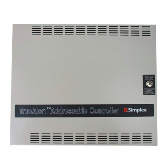
Chapter 1 Introduction to the TrueAlert Addressable Controller ™ Introduction The 4009-9401 TrueAlert Addressable Controller is a self-contained adjunct panel for use with TrueAlert addressable notification appliances. The base version of the Addressable Controller is a single-board system consisting of three Signaling Line Circuit (SLC) channels, a power supply ™... -
Page 10: Introduction To Truealert
Introduction to TrueAlert Overview TrueAlert notification appliance operation provides power, control, and supervision of horns and strobes over a single pair of wires. The controlling TrueAlert channel digitally communicates with each appliance and receives a response to verify the appliance’s presence on the channel. When required, the TrueAlert channel provides a digital command to control appliance operation. -
Page 11: Overview
Wiring Diagram 842-158). The Simplex 4100 or 4020 FACPs can interface to the TrueAlert Addressable Controller via a Remote Unit Interface (RUI). Diagnostic features are enabled and disabled through the front panel user interface. The quantity of TrueAlert Addressable Controllers that can be used is limited only by the number of card addresses available (out of the total of 119). - Page 12 The 4009 TrueAlert Addressable Controller, Continued Overview, continued The Hardwired NAC Interface uses two conventional NACs from the host FACP. One NAC is used to enable operation of the strobe appliances (so that they are On Until Silenced), and a second NAC is used to enable operation of the horn appliances (so that they are On Until Reset).
-
Page 13: Control Types
TrueAlert Control activate the appliances connected to the Addressable Controller. The hardwired NAC control inputs provide backward compatibility with other Simplex panels. In the hardwired mode, the configuration of the Addressable Controller is configured via two DIP switches (Hardware Configuration Switch (SW4) and Address/Software Configuration Switch (SW5)). Each input (called Hardwire Control Channel 1 and Channel 2, respectively, on TB7) simulates a typical hardwired notification appliance, as seen from the host panel. -
Page 14: Overview
Hardware Components Overview This section describes the hardware on the 4009 board. Use Figure 1-2 to locate the items described on this page. TrueAlert SLC The Addressable Controller system board provides three TrueAlert SLC channels. Channels 1 Channels through 3 are Class B TrueAlert signaling line circuits. Field wiring terminations are provided for 12 AWG to 18 AWG wire (twisted pair wire is required). -
Page 15: Figure 1-2. 4009 Truealert Addressable Controller System Board
Hardware Components, Continued IDNet CONTROL INTERFACE ADDRESS/SOFTWARE CONFIGURATION TB3, TB4, TB5 DIP SWITCH TRUEALERT SLC LED(s) E-A RUI CONTROL HARDWARE CHANNELS TROUBLE INDICATORS INTERFACE CONFIGURATION DIP SWITCH P2 AND P3 FOR CLASS A ADAPTER CARD SLC LEDs (CH1-CH3) SW1, SW2, SLC DEVICE LED 9 SWITCHES... -
Page 16: Figure 1-3. System Trouble Indicators
Hardware Components, Continued System Trouble The system trouble indicators consist of a bank of five yellow LEDs (see Figure 1-2 for location Indicators of LEDs) that are used to signify various trouble conditions within the Addressable Controller (LEDs E-A) system. Only one trouble at a time is indicated, with the highest trouble state indicated first. When that trouble clears, the next highest trouble state is indicated. -
Page 17: System Trouble Messages
Hardware Components, Continued System Trouble Tables 1-1 and 1-2, below, list the messages that appear on the FACP displays for each type of Messages trouble. Note: On hardwired systems, all troubles are displayed as “Open Circuit Trouble.” Table 1-1. System Trouble Messages Trouble Description 4010 IDNet Display 4100/4020 RUI Display... -
Page 18: Isolating Earth Grounds
Hardware Components, Continued Isolating Earth To determine which channel is in an Earth Ground trouble condition in any wiring mode, Grounds 1. When the Addressable Controller LEDs indicates a system trouble of Positive or Negative Earth Ground, reinitialize the Addressable Controller (typically by switching any DIP switch on the board). - Page 19 Chapter 2 System Configuration and Installation Overview The 4009 TrueAlert Addressable Controller can be configured to work with IDNet, RUI, or hardwired systems. This chapter describes how the DIP switches can be used to set up configurations, and goes on to describe the installation process common to all configurations. In this Chapter The table below lists the topics in this chapter.
-
Page 20: System Overview: Applications Diagram
System Overview: Applications Diagram Illustration Figure 2-1 summarizes the connections between the 4009 TrueAlert Addressable Controller, FACPs, and peripheral appliances. The figure shows example connections. Refer to 842-158 Field Wiring Diagram for instructions. Figure 2-1. 4009 TrueAlert Applications Diagram firealarmresources.com... -
Page 21: System Overview: Selective Signaling
System Overview: Selective Signaling Figure 2-2 shows that selective signaling can only be done with an RUI connection to a 4100U fire Alarm Control Illustration Panel. Figure 2-2. Selective Signaling Example firealarmresources.com... -
Page 22: System Configuration
System Configuration Overview This section describes how to use the DIP switches on the 4009 TrueAlert Addressable Controller board for setting addresses and optional features. SLC Appliance DIP The SLC Appliance Switches (SW1, SW2, SW3) are 8-position DIP switches. Use these switches Switches to set the number of appliances connected to each SLC. -
Page 23: Hardware Configuration Dip Switch (Sw4)
System Configuration, Continued Hardware The 8-position Hardware Configuration DIP Switch (SW4) is used to configure what hardware is Configuration DIP present and supervised by the Addressable Controller, and how the hardware is used. The Switch (SW4) Hardware Configuration Switch is located to the right of the channel indicator LEDs (E-A indicators) on the system board (see Figure 1-2). - Page 24 System Configuration, Continued Hardware Manual Real Appliance Test. Activates a test mode so that appliances can be manually tested Configuration DIP one at a time. The manual real appliance test makes a given notification appliance report its Switch (SW4), address and emits an alarm. Place a magnet on the appropriate area of the notification appliance to continued initiate a real appliance test.
- Page 25 System Configuration, Continued Hardware IDNet Host. Selected when the TrueAlert Addressable Controller is used with a 4010 FACP. Configuration DIP Switch (SW4), IMPORTANT: continued • The Addressable Controller cannot be connected to hardwired NAC channels (TB7) and an IDNet host (TB2) at the same time. Make sure only one interface is selected (IDNet, RUI, or Hardwired).
-
Page 26: Address/Software Configuration Dip Switch (Sw5)
System Configuration, Continued Address/Software The Address/Software Configuration Switch (SW5) is an 8-position DIP switch. The Configuration DIP Address/Software Configuration Switch is located to the right of the Hardware Configuration Switch (SW5) Switch (SW4) on the system board. When the Addressable Controller is operating as an addressable IDNet or RUI peripheral, this switch sets the Addressable Controller address. -
Page 27: Figure 2-5. Rui Address Settings (Sw5)
System Configuration, Continued Address/Software Figure 2-4, below, applies to RUI mode only. Configuration DIP Switch (SW5), Use a small screwdriver or pen to set the switches. continued Note: DIP switch in “1” position is ON while DIP switch in “0” position is OFF. DIP SWITCH IS SHOWN SET AT ADDRESS 7. - Page 28 System Configuration, Continued Address/Software When the 4009 operates as a non-addressable NAC extender, Switch SW5 configures the Configuration DIP operation of the output SLCs, based on the state of the two NAC control inputs. Refer to Switch (SW5), Table 2-2 for SLC control operation settings. continued Table 2-4.
-
Page 29: System Installation
Addressable Controller. Be sure that you are thoroughly familiar with this information before installing the 4009 TrueAlert Addressable Controller. To help you with installation of this and other Simplex Fire Alarm equipment, use How to Wire a Building for a Fire Alarm System (FA2-91-001 or 575-892) for general reference. -
Page 30: Required Documentation
System Installation, Continued Required The following documentation may be required: Documentation • Field Wiring Diagram 842-158 • 4009-9812 Class A Adapter Option Card Installation Instructions (574-763) • 4009-9809 IDNet Repeater Option Card Installation Instructions (574-327) • 4009-9810/-9811 Fiber Optic Link Option Installation Instructions (574-182) •... -
Page 31: Mounting The 4009 Truealert Addressable Controller
System Installation, Continued Mounting the 4009 Use the following procedure when mounting a TrueAlert Addressable Controller. TrueAlert Addressable CAUTION: Read all instructions carefully before cutting conduit/service entrances Controller and installing back box. Failure to comply with all installation requirements may result in a violation of UL or FCC regulations. 1. -
Page 32: Wiring The 4009 Truealert Addressable Controller
System Installation, Continued 4. Mount the back box to the wall so that the top of the enclosure is no more than eight feet Mounting the 4009 above the floor. The back box must be level and plumb. For surface mounting, use the TrueAlert Addressable teardrop and clearance holes located in the rear of the box and screw to wall. -
Page 33: System Power Requirements
System Installation, Continued System Power AC Input - 120VAC, 3 amperes, 60Hz Requirements Battery Input - 24VDC, 8 amperes TRUEALERT CHANNEL SIGNALING LINE CIRCUITS: THREE CLASS B/STYLE CIRCUITS STANDARD TO AUDIBLE AND/OR VISIBLE NOTIFICATION APPLIANCES (CLASS A/STYLE 6 CIRCUITS AVAILABLE) CIRCUITS RATED AT 2 1/2A @ 2 VDC PER CIRCUIT, POWER LIMITED 8A TOTAL POWER AVAILABLE... -
Page 34: Mounting And Wiring Peripheral Appliances
System Installation, Continued Mounting and Wiring Refer to Field Wiring Diagram 842-158 for detailed information and the installation instructions Peripheral for each appliance during peripheral appliance installation. The procedure listed below is a Appliances general outline for installing the 4009 peripheral appliances. 1. -
Page 35: Installing Option Interfaces
Installing Option Interfaces Overview The 4009 TrueAlert Addressable Controller supports several option add-on cards: 4009-9812 Class A Adapter Option Card. Allows fault tolerance in the case of open circuit wiring faults. One card provides Class A/Style 6 functionality for three TrueAlert SLCs. See 4009-9812 Class A Adapter Option Card Installation Instructions (574-763). - Page 36 firealarmresources.com...
-
Page 37: Chapter 3 4010 Panel Programming
Chapter 3 4010 Panel Programming Overview The 4009 TrueAlert Addressable Controller can be configured to work with the 4010 via programming at the 4010 panel. The panel programmer has the capability of auto-detecting new hardware, so that a 4009 TrueAlert Addressable Controller can be added to an existing configuration. Alternatively, the panel programmer can be used to manually add the 4009 TrueAlert Addressable Controller to the system setup. -
Page 38: Overview
4010 Programming Steps Overview Each step in this section is intended to be read sequentially, so that the last instruction from “Step 1. Starting the Programmer,” for example, leads directly to the first instruction in “Step 2. Adding an IDNet Point…” Read the entire section to make sure you make all the necessary configurations. - Page 39 4010 Programming Steps, Continued Step 2: Use the following instructions to add a 4009 IDNet point for the 4009 TrueAlert Addressable Adding an IDNet Controller. Point for the 4009 TrueAlert 1. From the Programming: [Configure Points] menu item, press ENTER. Addressable Controller 2.
-
Page 40: Step 3: Configuring 4009 Slc Point Types
4010 Programming Steps, Continued Step 3: 1. Press NEXT until the Configure Point: [NACs] menu item appears. Press ENTER. Configuring 4009 2. The display reads NAC Circuit: SIG 1 with a point type of Signal Circuit. SLC Point Types Press NEXT or PREVIOUS until IDNET M1-x: 4009A NAC 1 with a point type of Signal Circuit appears. -
Page 41: Step 5: Saving A Configuration
4010 Programming Steps, Continued Step 5: 1. Press NEXT until you get to Programming: [Save CFIG], and press ENTER. Press Saving a ENTER again at the prompt. Configuration 2. The display indicates the panel is saving and then restoring the CFIG and the labels. When the system is done saving, it reboots. -
Page 42: Deleting The 4009 Truealert Addressable Controller
Deleting the 4009 TrueAlert Addressable Controller Overview To delete a 4009 TrueAlert Addressable Controller from the list of device types from the Programming menu: 1. From the Programming: [Configure Points] menu item, press ENTER. 2. Press NEXT until the Configure Point: [ZAMS/RIAMS/IAMS] menu item comes up. -
Page 43: 4010 Quick Cfig
4010 Quick CFIG Overview The Quick CFIG option can be used instead of manual programming. Quick CFIG automatically detects new hardware, and assigns default settings which you can modify later by using the programmer manually. Quick CFIG Steps To add one or more 4009 TrueAlert Addressable Controllers using Quick CFIG: 1. - Page 44 firealarmresources.com...
- Page 45 Index DIP switch settings, 2-7 Horn volume settings, 2-7 Addressable Controller, 1-1 block diagram, 2-2 deleting, 3-6 IDNet interface description, 1-3 adding points, 3-3 hardwired interface, 1-4 address settings, 2-8 IDNet interface, 1-3 description, 1-3, 1-5 2-13 DIP switch settings, 2-7 mounting, point label programming, 3-4 power requirements, 2-15...
- Page 46 point labels, 3-4 signal programming point types, 3-4 4010 (panel), 3-5 Silent Appliance Test Quick CFIG, Global, 2-5 saving, 3-5 Manual, 2-6 signals, 3-5 SLC channels starting up, 3-2 on Addressable Controller, 1-6 point label programming, 3-4 overview, 1-2 point type programming, 3-4 programming 4010 panel.
- Page 47 asdf firealarmresources.com...
- Page 48 574-762 Rev. E © 2005, 2007 Tyco Safety Products Westminster, Westminster, MA 01441-001 USA. Specifications and other information shown were current as of publication and are subject to change without notice. firealarmresources.com...
Need help?
Do you have a question about the TrueAlert 4009-9401 and is the answer not in the manual?
Questions and answers