Simplex 4010 Installation Instructions Manual
Suppression release kits
Hide thumbs
Also See for 4010:
- Installing and operating insructions (198 pages) ,
- Applications manual (85 pages) ,
- Service manual (72 pages)
Advertisement
Cautions and Warnings
Overview
In this Publication
¤
1998 Simplex Time Recorder Co., Gardner, MA 01441-0001 USA
All specifications and other information shown were current as of publication, and are subject to change without notice
Technical Manuals Online! - http://www.tech-man.com
4010 Suppression Release Kits
DO NOT INSTALL ANY SIMPLEX PRODUCT THAT APPEARS
DAMAGED. Upon unpacking your Simplex product, inspect the contents of the
carton for shipping damage. If damage is apparent, immediately file a claim
with the carrier and notify Simplex.
ELECTRICAL HAZARD - Disconnect electrical power when making any
internal adjustments or repairs. Servicing should be performed by qualified
Simplex Representatives.
STATIC HAZARD - Static electricity can damage components. Therefore,
handle as follows:
1.
Ground yourself before opening or installing components (use the 553-484
Static Control Kit).
2.
Keep uninstalled component wrapped in anti-static material at all times.
RADIO FREQUENCY ENERGY - This equipment generates, uses, and can
radiate radio frequency energy and if not installed and used in accordance with
the instruction manual, may cause interference to radio communications. It has
been tested and found to comply with the limits for a Class A computing device
pursuant to Subpart J of Part 15 of FCC Rules, which are designed to provide
reasonable protection against such interference when operated in a commercial
environment. Operation of this equipment in a residential area is likely to cause
interference in which case the user at his own expense will be required to take
whatever measures may be required to correct the interference.
This publication shows how to install the 4010-9814 (120V) and the 4010-9824
(240V) Suppression Release Kits into a 4010 Fire Alarm Control Panel (FACP).
Refer to the 4010 Fire Alarm - Installation Instructions (574-052) for
configuration information. Refer to the 842-058 Field Wiring Diagram for
additional wiring information.
This publication discusses the following topics:
Topic
Overview
4010-9814 and -9824 Suppression Release Kits
Installation
Wiring
Power-Up and Checkout
Installation Instructions
See Page #
1
2
3
5
7
574-166
Rev. B
Advertisement
Table of Contents

Related Manuals for Simplex 4010


Summary of Contents for Simplex 4010
-
Page 1: Installation Instructions
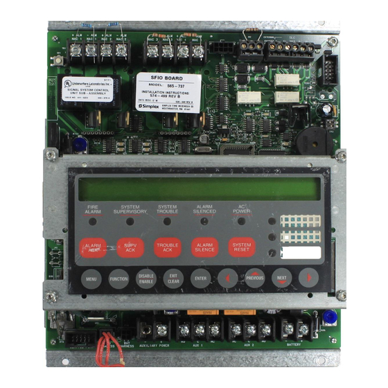
Overview This publication shows how to install the 4010-9814 (120V) and the 4010-9824 (240V) Suppression Release Kits into a 4010 Fire Alarm Control Panel (FACP). Refer to the 4010 Fire Alarm - Installation Instructions (574-052) for configuration information. - Page 2 4010-9814 and -9824 Suppression Release Kits Overview When the suppression function is controlled by the 4010 Fire Alarm Control Panel, a Suppression Release Kit (power supply 565-793) can be added to supply power for this function. The suppression release kit provides filtered/regulated 24VDC, 4A power for Notification.
- Page 3 Mounting The 4010-9814 and -9824 Suppression Release Kits install in their own hardware slot located to the right of the 4010 SFI/O module (see Figure 2). Use Steps 1 through 3 to mount the suppression release kit. Disconnect battery and then AC power from the FACP.
- Page 4 Installation, Continued Applying the Suppression When the suppression function is controlled by the 4010 Fire Alarm Control Release Label Panel, the panel must be labeled to indicate this fact. The label lets all persons servicing the system know that the panel is configured for suppression release and that they must disable all releasing device circuits before servicing the panel.
- Page 5 Non-Power Limited wiring. You must maintain a 1/4-inch separation between these two types of wiring. AC Wiring Follow Steps 1 through 4 to wire AC power to the 4010-9814 or -9824 suppression release kit. Disconnect battery and then AC power from the FACP.
- Page 6 The suppression release kit requires power and communications connections to Wiring the 4010 SFI/O board. Use Steps 1 through 3 to connect a power and communications harness from the suppression release kit to the 4010 FACP. Both harness connectors are keyed for correct connection.
- Page 7 15 minutes and seek immediate medical attention. After applying power to the system, use the following list to check the 4010 for proper operation. Check that the green AC Power LED is ON.
- Page 8 574-166 Rev. B Technical Manuals Online! - http://www.tech-man.com...
Need help?
Do you have a question about the 4010 and is the answer not in the manual?
Questions and answers
• Los únicos elementos que disparan sin retardos ni secuencia son los pulsadores • En todo lo que sea oficina necesitamos que el disparo sea cruzado para que active la secuencia tiene que dispararse un ambiente y un sobre o un ambiente y un bajo piso, si la programación de la central lo permite, cualquier sensor que se active les llegue al VES como un evento de fuego, pero que active la secuencia de disparo de la central si al menos 2 elementos están activos • Todo lo que sea deposito que este cubierto por barreras el disparo es cualquiera de las barreras que se active dispara la secuencia positiva de la central • Vamos a probar la secuencia positiva al generarse un disparo que nos de un tiempo de 3 minutos antes de activar el audio de evacuación • Si la central soporta como actualmente está instalada y diseñada, 3 circuitos de sirenas te adjunto una imagen **** las zonas que pretendemos, si no se dispone de salidas para los circuitos de sirena que el audio se active en todo el edificio, la idea es que el local 13 dispare el resto de los locales zona rojo y verde, la zona roja que dispare solamente el 13 y la zona verde dispare el 13 • las ECAS y válvulas lleguen como alarmas supervisadas, flujo de agua y cierre de válvula" Ademas se debe corregir los textos de DEPOSITOS que estan mal escritos.