
Related Manuals for Thermo Scientific 49i


Summary of Contents for Thermo Scientific 49i
- Page 1 Model 49i Instruction Manual UV Photometric O Analyzer Part number 102434-00 10Jan2008...
- Page 2 © 2007 Thermo Fisher Scientific Inc. All rights reserved. Specifications, terms and pricing are subject to change. Not all products are available in all countries. Please consult your local sales representative for details. Thermo Fisher Scientific Air Quality Instruments 27 Forge Parkway Franklin, MA 02038 1-508-520-0430 www.thermo.com/aqi...
-
Page 3: Weee Compliance
WEEE Compliance This product is required to comply with the European Union’s Waste Electrical & Electronic Equipment (WEEE) Directive 2002/96/EC. It is marked with the following symbol: Thermo Fisher Scientific has contracted with one or more recycling/disposal companies in each EU Member State, and this product should be disposed of or recycled through them. - Page 5 Equivalent Method Designation The Thermo Scientific Model 49i is designated by the United States Environmental Protection Agency (USEPA) as an Equivalent Method for the measurement of ambient concentrations of ozone pursuant with the requirements defined in the Code of Federal Regulations, Title 40, Part 53.
-
Page 7: Table Of Contents
Auto Range Mode..............3-11 Gas Units ................3-14 Range ................3-14 Set Custom Ranges ............3-16 Averaging Time..............3-17 Calibration Factors Menu .............3-18 Background..............3-18 Span Coefficient............3-20 Calibration Menu ..............3-21 Calibrate Zero..............3-22 Calibrate O Coefficient ............3-22 Zero/Span Check ...............3-23 Thermo Fisher Scientific Model 49i Instruction Manual... - Page 8 Intensity A and B ...............3-78 Zero and Span Check............3-79 Zero and Span Auto Calibration ........3-80 Ozonator Level 1-5 Check ..........3-80 Concentration ..............3-81 Service Menu ................3-83 Pressure Check..............3-83 Lamp Setting..............3-85 Detector Calibration ............3-86 Intensity Check..............3-86 viii Model 49i Instruction Manual Thermo Fisher Scientific...
- Page 9 Internal Ozonator Adjustment (Option) .......4-13 Chapter 5 Preventive Maintenance ...............5-1 Safety Precautions ..............5-2 Replacement Parts..............5-2 Outside Case Cleaning............5-2 Optical Bench Cleaning ............5-2 Lamp Replacement ..............5-3 Monitoring Detector Frequencies and Noise......5-4 Increasing Lamp Output............5-4 Monitoring Lamp Noise ............5-4 Thermo Fisher Scientific Model 49i Instruction Manual...
- Page 10 Measurement Interface Board Replacement ......7-21 Front Panel Board Replacement..........7-22 LCD Module Replacement ...........7-23 Optical Bench Replacement ..........7-24 Optical Bench Temperature Calibration .......7-26 Photometer Lamp Replacement ..........7-27 Photometer Lamp Voltage Adjustment .........7-28 Photometer Board Replacement..........7-29 Detector Replacement............7-30 Model 49i Instruction Manual Thermo Fisher Scientific...
- Page 11 Digital Output Board............8-7 I/O Expansion Board (Optional) .........8-7 Front Panel Connector Board ..........8-8 I/O Components ..............8-8 Analog Voltage Outputs............8-8 Analog Current Outputs (Optional) ........8-9 Analog Voltage Inputs (Optional) ........8-9 Digital Relay Outputs ............8-9 Digital Inputs...............8-9 Thermo Fisher Scientific Model 49i Instruction Manual...
- Page 12 Format Specifier for ASCII Responses....... B-44 Format Specifier for Binary Responses ......B-44 Format Specifier for Front-Panel Layout ......B-45 Appendix C MODBUS Protocol.................C-1 Serial Communication Parameters ......... C-2 TCP Communication Parameters .......... C-2 Model 49i Instruction Manual Thermo Fisher Scientific...
- Page 13 Block Checksum <BCC> ............D-3 Geysitech Commands ............D-3 Instrument Control Command (ST)........D-3 Data Sampling/Data Query Command (DA) .....D-4 Measurements Reported in Response to DA Command for 49i and 49i PS........D-7 Operating and Error Status ..........D-7 Thermo Fisher Scientific Model 49i Instruction Manual xiii...
- Page 14 Contents Model 49i Instruction Manual Thermo Fisher Scientific...
- Page 15 Pin-Out of Rear Panel Connector in Dual Range Mode ..3-10 Analog Output in Auto Range Mode ........3-12 Pin-Out of Rear Panel Connector in Auto Range Mode ..3-13 Model 49i Connected as Calibrator .........4-3 Model 49i Connected to Calibration Photometer and External Ozonator ............4-9 Ozonator Flow Scheme ............4-13...
- Page 16 Figures Flag Status ................B-11 Model 49i Instruction Manual Thermo Fisher Scientific...
- Page 17 Measurement Interface Board Connector Pin Descriptions ....6-17 Ozonator Power Supply Connector Pin Descriptions ......6-19 Photometer Power Supply Connector Pin Descriptions ......6-20 Model 49i Replacement Parts ..............7-4 Model 49i Cables ..................7-6 External Device Connection Components ..........7-6 Analog Output Channels and Rear Panel Pin Connections ....
- Page 18 Tables Read Registers for 49i ................C-9 Write Coils for 49i .................C-10 Operating Status for Model 49i and 49i Primary Standard ..... D-7 Error Status for Model 49i and 49i Primary Standard ......D-8 xviii Model 49i Instruction Manual Thermo Fisher Scientific...
-
Page 19: Chapter 1 Introduction
• Chapter 9 “Optional Equipment” describes the optional equipment that can be used with this analyzer. • Appendix A “Warranty” is a copy of the warranty statement. Thermo Fisher Scientific Model 49i Instruction Manual... - Page 20 The hazard or unsafe practice could result in minor to moderate personal injury if the warning is ignored. Equipment Damage The hazard or unsafe practice could result in property damage if the warning is ignored. Model 49i Instruction Manual Thermo Fisher Scientific...
- Page 21 The service procedures in this manual are restricted to qualified service personnel only. The Model 49i is supplied with a three-wire grounding cord. Under no circumstances should this grounding system be defeated. CAUTION If the LCD panel breaks, do not to let the liquid crystal contact your skin or clothes.
- Page 22 Service is available from exclusive distributors worldwide. Contact one of the phone numbers below for product support and technical information or visit us on the web at www.thermo.com/aqi. 1-866-282-0430 Toll Free 1-508-520-0430 International Thermo Fisher Scientific Model 49i Instruction Manual xxii...
-
Page 23: Introduction
Chapter 1 The Model 49i UV Photometric Ozone Analyzer combines proven detection technology, easy to use menu-driven software, and advanced diagnostics to offer unsurpassed flexibility and reliability. The Model 49i has the following features: • 320 x 240 graphics display •... -
Page 24: Principle Of Operation
I = UV light intensity of sample with ozone (sample gas) = UV light intensity of sample without ozone (reference gas) The sample is drawn into the Model 49i through the sample bulkhead and is split into two gas streams, as shown in Figure 1-1. One gas stream flows through an ozone scrubber to become the reference gas (I ). -
Page 25: Specifications
Figure 1-1. Model 49i Flow Schematic Specifications Table 1-1. Model 49i Specifications Preset ranges 0-0.05, 0.1, 0.2, 0.5, 1, 2, 5, 10, 20, 50, 100, 200 ppm... - Page 26 C-Link, MODBUS, and streaming data (all user selectable) Ethernet connection RJ45 connector for 10Mbs Ethernet connection, static or dynamic TCP/IP addressing In non condensing environments. Performance specifications based on operation within 20–30 °C range. Model 49i Instruction Manual Thermo Fisher Scientific...
-
Page 27: Installation
Equipment Damage Do not attempt to lift the instrument by the cover or other external fittings. Unpacking and The Model 49i is shipped complete in one container. If there is obvious Inspection damage to the shipping container when you receive the instrument, notify the carrier immediately and hold for inspection. -
Page 28: Remove The Packing Material
4. Remove the three shipping screws (Figure 2-2). Shipping Screws (3) Figure 2-2. Remove the Shipping Screws 5. Check for possible damage during shipment. 6. Check that all connectors and circuit boards are firmly attached. Model 49i Instruction Manual Thermo Fisher Scientific... -
Page 29: Setup Procedure
4. Plug the instrument into an outlet of the appropriate voltage and frequency. WARNING The Model 49i is supplied with a three-wire grounding cord. Under no circumstances should this grounding system be defeated. Thermo Fisher Scientific Model 49i Instruction Manual... - Page 30 Installation Setup Procedure Figure 2-3. Model 49i Rear Panel Instrument Bulkhead SAMPLE Vent to Exhaust Line at Atmospheric Pressure Input Gas Line Figure 2-4. Atmospheric Dump Bypass Plumbing Model 49i Instruction Manual Thermo Fisher Scientific...
-
Page 31: Connecting External Devices
Note Not all of the available I/O for the instrument are brought out on this terminal. If more I/O is desired, you must use an alternative connection method. Thermo Fisher Scientific Model 49i Instruction Manual... -
Page 32: I/O Terminal Board Views
Signal Description Analog1 Power_Fail_NC Analog ground Power_Fail_COM Analog2 Power_Fail_NO Analog ground TTL_Input1 Analog3 TTL_Input2 Analog ground TTL_Input3 Analog4 TTL_Input4 Analog ground Digital ground Analog5 TTL_Input5 Analog ground TTL_Input6 Analog6 TTL_Input7 Analog ground Digital ground Model 49i Instruction Manual Thermo Fisher Scientific... -
Page 33: D/O Terminal Board Views
Table 2-2. D/O Terminal Board Pin Descriptions Signal Description Signal Description Relay1_ContactA Relay7_ContactA Relay1_ContactB Relay7_ContactB Relay2_ContactA Relay8_ContactA Relay2_ContactB Relay8_ContactB Relay3_ContactA Relay9_ContactA Relay3_ContactB Relay9_ContactB Relay4_ContactA Relay10_ContactA Relay4_ContactB Relay10_ContactB Relay5_ContactA Solenoid_Drive_Output1 Relay5_ContactB +24V Relay6_ContactA Solenoid_Drive_Output2 Relay6_ContactB +24V Thermo Fisher Scientific Model 49i Instruction Manual... - Page 34 Table 2-3. 25-Pin Terminal Board Pin Descriptions Signal Description Signal Description IOut1 Analog_In1 GND_ISO Analog_In2 IOut2 Analog_In3 GND_ISO GNDD IOut3 Analog_In4 GND_ISO Analog_In5 IOut4 Analog_In6 GND_ISO GNDD IOut5 Analog_In7 GND_ISO Analog_In8 IOut6 GNDD GND_ISO GNDD Model 49i Instruction Manual Thermo Fisher Scientific...
-
Page 35: Startup
3. Set instrument parameters such as operating ranges and averaging times to appropriate settings. For more information about instrument parameters, see the “Operation” chapter. 4. Before beginning actual instrument monitoring, perform a multipoint calibration as described in the “Calibration” chapter. Thermo Fisher Scientific Model 49i Instruction Manual... - Page 36 Installation Startup 2-10 Model 49i Instruction Manual Thermo Fisher Scientific...
-
Page 37: Operation
• “Service Menu” page 3-83 describes service related menu items. • “Password Menu” page 3-97 describes how to enter/change a password, lock and unlock the instrument. Thermo Fisher Scientific Model 49i Instruction Manual... -
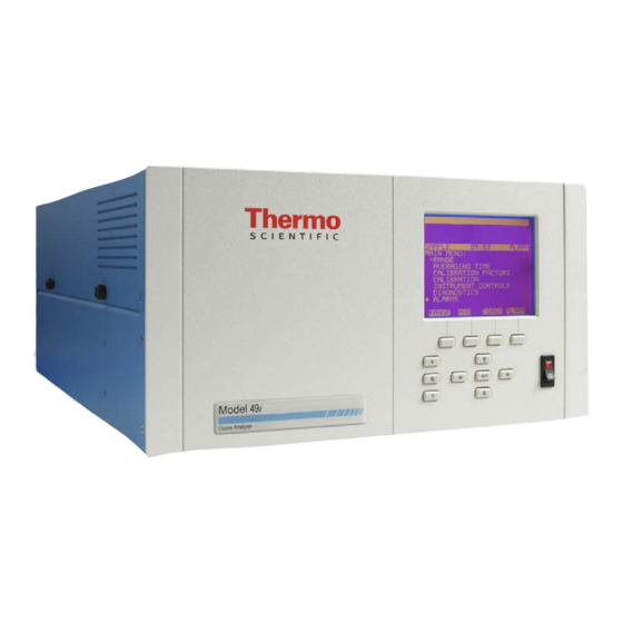
Page 38: Display
Figure 3-1. 49i Front Panel Display CAUTION If the LCD panel breaks, do not let the liquid crystal contact your skin or clothes. If the liquid crystal contacts your skin or clothes, wash it off immediately using soap and water. -
Page 39: Pushbuttons
) move the cursor up, down, left, and right or = Left, Right change values and states in specific screens. = Enter is used to select a menu item, accept/set/save a change, and/or toggle on/off functions. Thermo Fisher Scientific Model 49i Instruction Manual... -
Page 40: Soft Keys
DIAGS ALARM Software Overview The Model 49i utilizes the menu-driven software illustrated by the flowchart in Figure 3-3. The Power-Up screen, shown at the top of the flowchart, is displayed each time the instrument is turned on. This screen is displayed while the instrument is warming up and performing self-checks. -
Page 42: Power-Up Screen
Operation Software Overview Power-Up Screen The Power-Up screen is displayed on power up of the Model 49i. The Self-Test is displayed while the internal components are warming up and diagnostic checks are performed. Run Screen The Run screen displays the O concentration. -
Page 43: Main Menu
• Press to return to the Main Menu or to return to the Run screen. MAIN MENU: >RANGE AVERAGING TIME CALIBRATION FACTORS CALIBRATION INSTRUMENT CONTROLS DIAGNOSTICS ALARMS RANGE DIAGS ALARM SERVICE PASSWORD Thermo Fisher Scientific Model 49i Instruction Manual... -
Page 44: Range Menu
By default, the analog outputs are arranged on the rear panel connector as shown in Figure 3-4. See Table 3-2 for channels and pin connections. Single range mode may be selected from the “Range Mode Select” in the “Service Menu”, later in this chapter. Model 49i Instruction Manual Thermo Fisher Scientific... -
Page 45: Pin-Out Of Rear Panel Connector In Single Range Mode
16, 18, 19, 35, 37 2, 4, 6, 8, 10, 12 Signal Ground Note All channels are user definable. If any customization has been made to the analog output configuration, the default selections may not apply. Thermo Fisher Scientific Model 49i Instruction Manual... -
Page 46: Dual Range Mode
Dual range mode may be selected from the “Range Mode Select” in the “Service Menu”, later in this chapter. Figure 3-5. Pin-Out of Rear Panel Connector in Dual Range Mode 3-10 Model 49i Instruction Manual Thermo Fisher Scientific... -
Page 47: Auto Range Mode
For example, if the low O range is set to 0–50 ppb and the high O range is set to 0–20,000 ppb. Thermo Fisher Scientific Model 49i Instruction Manual 3-11... - Page 48 Figure 3-7. See Table 3-4 for channels and pin connections. Auto range mode may be selected from the “Range Mode Select” in the “Service Menu”, later in this chapter. 3-12 Model 49i Instruction Manual Thermo Fisher Scientific...
-
Page 49: Pin-Out Of Rear Panel Connector In Auto Range Mode
16, 18, 19, 35, 37 2, 4, 6, 8, 10, 12 Signal Ground Note All channels are user definable. If any customization has been made to the analog output configuration, the default selections may not apply. Thermo Fisher Scientific Model 49i Instruction Manual 3-13... -
Page 50: Gas Units
The range screen is similar for the single, dual, and auto range modes. The only difference between the screens are the words “High” or “Low” displayed to indicate which range is displayed. For more 3-14 Model 49i Instruction Manual Thermo Fisher Scientific... -
Page 51: O3 Range
SAVE VALUE RANGE DIAGS ALARM Table 3-5. Operating Ranges μg/m mg/m 0.05 0.10 0.20 0.50 1,000 1,000 2,000 2,000 5,000 5,000 10,000 10,000 20,000 20,000 50,000 50,000 100,000 100,000 200,000 200,000 400,000 Thermo Fisher Scientific Model 49i Instruction Manual 3-15... -
Page 52: Set Custom Ranges
In the Main Menu, choose Range > Set Custom Ranges > Custom range 1, 2, or 3. • to move the cursor left or right. • to increment or decrement the numeric value. • Press to save the new range. 3-16 Model 49i Instruction Manual Thermo Fisher Scientific... -
Page 53: Averaging Time
“Cycle Time”, later in this chapter. • In the Main Menu, choose Averaging Time. • to scroll through a list of choices. • Press to save the averaging time. Thermo Fisher Scientific Model 49i Instruction Manual 3-17... -
Page 54: Calibration Factors Menu
The background is the amount of signal read by the analyzer while sampling zero air. Before the analyzer sets the O reading to zero, it stores the value as the O background. 3-18 Model 49i Instruction Manual Thermo Fisher Scientific... - Page 55 O reading disappears. • In the Main Menu, choose Calibration Factors > O Background. • to increment or decrement the proposed background value. Press • to save the new background. Thermo Fisher Scientific Model 49i Instruction Manual 3-19...
-
Page 56: O 3 Span Coefficient
The example below shows the coefficient screen in single mode. • In the Main Menu, choose Calibration Factors > O Coef. • to increment or decrement the coefficient value. • Press to save the new coefficient. 3-20 Model 49i Instruction Manual Thermo Fisher Scientific... -
Page 57: Calibration Menu
For example, a low O range of 50 ppb and a high O range of 20,000 ppb. For more information about calibration, see Chapter 4, “Calibration”. Thermo Fisher Scientific Model 49i Instruction Manual 3-21... -
Page 58: Calibrate Zero
The next line of the display is where the calibration gas concentration is entered. In dual or auto range modes, “High” or “Low” is displayed to indicate the calibration of the high or low coefficient. 3-22 Model 49i Instruction Manual Thermo Fisher Scientific... -
Page 59: Zero/Span Check
Zero and Span Calibration Reset are toggle items that change between yes or no when selected, and displayed if auto calibration is installed. • In the Main Menu, choose Calibration > Zero/Span Check. Thermo Fisher Scientific Model 49i Instruction Manual 3-23... - Page 60 Periods between 0 and 999 hours are acceptable. To turn the zero/span check off, set the period to 0. • In the Main Menu, choose Calibration > Zero/Span Check > Period Hours. 3-24 Model 49i Instruction Manual Thermo Fisher Scientific...
- Page 61 • Press to save the duration value. ZERO DURATION: CURRENTLY: 30 MIN SET TO: 31 MIN ? MOVE CURSOR CHANGE VALUE SAVE RANGE DIAGS ALARM Thermo Fisher Scientific Model 49i Instruction Manual 3-25...
- Page 62 This value may be set from 1 to 10, with 1 as default. • In the Main Menu, choose Calibration > Zero/Span Check > Zero/Span Ratio. • to increment and decrement the numeric value. • Press to save the ratio value. 3-26 Model 49i Instruction Manual Thermo Fisher Scientific...
-
Page 63: Instrument Controls Menu
The Custom Levels menu lists four custom levels: 1, 2, 3, 4, and 5. Custom levels deal with ozonator control and configuration. This menu is only displayed if the ozonator option is installed. • In the Main Menu, choose Instrument Controls > Custom Levels. Thermo Fisher Scientific Model 49i Instruction Manual 3-27... -
Page 64: Pump
The Pump screen allows the user to toggle the pump on and off. • In the Main Menu, choose Instrument Controls > Pump. • Press to toggle and set the pump on or off. 3-28 Model 49i Instruction Manual Thermo Fisher Scientific... -
Page 65: Ozonator Solenoid
“Averaging Time” earlier in the this chapter. • In the Main Menu, choose Instrument Controls > Cycle Time. • Press to toggle and set the cycle time standard or fast. Thermo Fisher Scientific Model 49i Instruction Manual 3-29... -
Page 66: Temperature Compensation
The Compensation Model 49i can be operated with or without temperature compensation. When temperature compensation is on, the display shows the sample gas temperature (measured by a thermistor on the Interface board). When temperature compensation is off, the display shows the standard temperature of 0.0 °C. -
Page 67: Datalogging Settings
• In the Main Menu, choose Instrument Controls > Datalogging Settings > Select SREC/LREC. • Press to toggle and set to either short record or long record format. Thermo Fisher Scientific Model 49i Instruction Manual 3-31... - Page 68 • to move the cursor left or right. • to increment or decrement the numeric value. • Press to set the starting record and continue to the record display screen. 3-32 Model 49i Instruction Manual Thermo Fisher Scientific...
- Page 69 • to advance to next field. • Press to set the date and time of the first record to be displayed and continue to the record display screen. Thermo Fisher Scientific Model 49i Instruction Manual 3-33...
- Page 70 The Erase Log is used to erase all saved data for the selected record type (not all short records and long records). • In the Main Menu, choose Instrument Controls > Datalogging Settings > Erase Log. • Press to erase all data. • Press to confirm erasure. 3-34 Model 49i Instruction Manual Thermo Fisher Scientific...
- Page 71 Choices and Concentrations, Other Measurements, and Analog Inputs (if the I/O expansion board is installed). In the Main Menu, choose Instrument Controls > Datalogging Settings > Select Content > Field 1-32. Thermo Fisher Scientific Model 49i Instruction Manual 3-35...
- Page 72 To change the selected record format and erase record log file data, see “Commit Content” below. • In the Main Menu, choose Instrument Controls > Datalogging Settings > Select Content > Select Field > Other Measurements. 3-36 Model 49i Instruction Manual Thermo Fisher Scientific...
- Page 73 • Press to select a new choice. ANALOG INPUTS: >NONE ANALOG IN 1 ANALOG IN 2 ANALOG IN 3 ANALOG IN 4 ANALOG IN 5 ANALOG IN 6 RANGE DIAGS ALARM Thermo Fisher Scientific Model 49i Instruction Manual 3-37...
- Page 74 In the Main Menu, choose Instrument Controls > Datalogging Settings > Reset to Default Content. • Press to reset selected record format and erase record log file data. • Press to confirm reset. 3-38 Model 49i Instruction Manual Thermo Fisher Scientific...
- Page 75 In the Main Menu, choose Instrument Controls > Datalogging Settings > Configure Datalogging > Logging Period Min. • to scroll through a list of choices. • Press to set the logging period. Thermo Fisher Scientific Model 49i Instruction Manual 3-39...
- Page 76 Data treatment doesn’t apply to all data, just to the concentration measurement. All other data points log the current value at the end of the interval. 3-40 Model 49i Instruction Manual Thermo Fisher Scientific...
-
Page 77: Communication Settings
Baud rates of 1200, 2400, 4800, and 9600, 19200, 38400, 57600, and 115200 are available. • In the Main Menu, choose Instrument Controls > Communication Settings > Baud Rate. • to scroll through a list of choices. Thermo Fisher Scientific Model 49i Instruction Manual 3-41... - Page 78 ID number if two or more of the same instrument are connected to one computer. Valid Instrument ID numbers are from 0 to 127. The Model 49i has a default Instrument ID of 49. For more information about the Instrument ID, see Appendix B “C-Link Protocol Commands”...
- Page 79 >INTERVAL 10 SEC ADD LABELS PREPEND TIMESTAMP ITEM 1 ITEM 2 CELLAI ITEM 3 CELLBI ITEM 4 NONE RANGE DIAGS ALARM CHOOSE STREAM DATA: >CONCENTRATIONS OTHER MEASUREMENTS ANALOG INPUTS RANGE DIAGS ALARM Thermo Fisher Scientific Model 49i Instruction Manual 3-43...
- Page 80 Settings > Streaming Data Config > Select Item > Concentrations. • to move the cursor up and down. • Press to select a new choice. CONCENTRATIONS: >NONE <-- LO O3 HI O3 RANGE STATUS RANGE DIAGS ALARM 3-44 Model 49i Instruction Manual Thermo Fisher Scientific...
- Page 81 In the Main Menu, choose Instrument Controls > Communication Settings > Streaming Data Config > Select Item > Analog Inputs. • to move the cursor up and down. • Press to select a new choice. Thermo Fisher Scientific Model 49i Instruction Manual 3-45...
- Page 82 Note The instrument power must be cycled after this parameter has been changed for the change to take effect. • In the Main Menu, choose Instrument Controls > Communication Settings > TCP/IP Settings. 3-46 Model 49i Instruction Manual Thermo Fisher Scientific...
- Page 83 In the Main Menu, choose Instrument Controls > Communication Settings > TCP/IP Settings > IP Address. • to move and change the value of the IP address. • Press to save the new address. Thermo Fisher Scientific Model 49i Instruction Manual 3-47...
- Page 84 DHCP, see “Use DHCP.” • In the Main Menu, choose Instrument Controls > Communication Settings > TCP/IP Settings > Gateway. • to move and change the value of the gateway address. 3-48 Model 49i Instruction Manual Thermo Fisher Scientific...
-
Page 85: I/O Configuration
The I/O Configuration menu deals with configuration of the analyzer’s I/O system. The analog input configuration is displayed only if the I/O expansion board option is installed. • In the Main Menu, choose Instrument Controls > I/O Configuration. Thermo Fisher Scientific Model 49i Instruction Manual 3-49... - Page 86 Logic State The Logic State screen is used to change the I/O relay to either normally open or normally closed. • Press to toggle and set the logic state open or closed. 3-50 Model 49i Instruction Manual Thermo Fisher Scientific...
- Page 87 In the Main Menu, choose Instrument Controls > I/O Configuration > Output Relay Settings > Select Relay > Instrument State > Alarms. • to scroll through a list of choices. • Press to save the new selection for the relay. Thermo Fisher Scientific Model 49i Instruction Manual 3-51...
- Page 88 NON ALARM STATUS ITEMS: >NONE AUTORANGE SERVICE UNITS ZERO MODE SPAN MODE SAMPLE MODE RANGE DIAGS ALARM OZ LEVEL 1 OZ LEVEL 2 OZ LEVEL 3 OZ LEVEL 4 OZ LEVEL 5 PURGE MODE 3-52 Model 49i Instruction Manual Thermo Fisher Scientific...
- Page 89 • Press to toggle and set the logic state open or closed. DIGITAL INPUT SETUP: >LOGIC STATE OPEN INSTRUMENT ACTION RANGE DIAGS ALARM Thermo Fisher Scientific Model 49i Instruction Manual 3-53...
- Page 90 • In the Main Menu, choose Instrument Controls > I/O Configuration > Analog Output Config. • to move the cursor up and down. • Press to select a choice. 3-54 Model 49i Instruction Manual Thermo Fisher Scientific...
- Page 91 • Press to save the new range. SELECT OUTPUT RANGE: SELECTED OUTPUT: V ALL CURRENTLY: 0-10V SET TO: 0-5V CHANGE VALUE SAVE RANGE DIAGS ALARM Thermo Fisher Scientific Model 49i Instruction Manual 3-55...
- Page 92 User-set alarm max value Pressure User-set alarm min value User-set alarm max value Bench Temp User-set alarm min value User-set alarm max value Lamp Temp User-set alarm min value User-set alarm max value 3-56 Model 49i Instruction Manual Thermo Fisher Scientific...
- Page 93 CHOOSE ITEM SIGNAL: CONCENTRATIONS OTHER MEASUREMENTS ANALOG INPUTS RANGE DIAGS ALARM CHOOSE SIGNAL - CONC SELECTED OUTPUT: CURRENTLY: O3 SET TO: NONE CHANGE VALUE SAVE RANGE DIAGS ALARM Thermo Fisher Scientific Model 49i Instruction Manual 3-57...
- Page 94 In the Main Menu, choose Instrument Controls > I/O Configuration > Analog Input Config. ANALOG INPUT CONFIG: >CHANNEL 1 CHANNEL 2 CHANNEL 3 CHANNEL 4 CHANNEL 5 CHANNEL 6 CHANNEL 7 RANGE DIAGS ALARM 3-58 Model 49i Instruction Manual Thermo Fisher Scientific...
- Page 95 V (volts). • In the Main Menu, choose Instrument Controls > I/O Configuration > Analog Input Config > Select Channel > Units. • Press to save the new value. Thermo Fisher Scientific Model 49i Instruction Manual 3-59...
- Page 96 In the Main Menu, choose Instrument Controls > I/O Configuration > Analog Input Config > Select Channel > Table Points. • to move the cursor up and down. • Press to save the new value. 3-60 Model 49i Instruction Manual Thermo Fisher Scientific...
- Page 97 Analog Input Config > Select Channel > Select Point > Volts. • to move the cursor left or right. • to move the cursor up and down. • Press to save the new value. Thermo Fisher Scientific Model 49i Instruction Manual 3-61...
-
Page 98: Screen Contrast
• In the Main Menu, choose Instrument Controls > Screen Contrast. • to increment or decrement the screen contrast. 3-62 Model 49i Instruction Manual Thermo Fisher Scientific... -
Page 99: Service Mode
Model 49i. For more information about the service mode, see “Service Menu” later in this chapter. Note The service mode should be turned off when finished, as it prevents remote operation. -
Page 100: Diagnostics Menu
Program Version The Program Version screen (read only) shows the version number of the program installed. Prior to contacting the factory with any questions regarding the instrument, please note the program version number. 3-64 Model 49i Instruction Manual Thermo Fisher Scientific... -
Page 101: Voltages
DIAGS ALARM Motherboard Voltages The Motherboard screen (read only) is used to display the current voltage readings on the motherboard. • In the Main Menu, choose Diagnostics > Voltages > Motherboard Voltages. Thermo Fisher Scientific Model 49i Instruction Manual 3-65... - Page 102 In the Main Menu, choose Diagnostics > Voltages > I/O Board Voltages. I/O BOARD VOLTAGES: 3.3 SUPPLY 3.3 V 5.0 SUPPLY 5.0 V 24.0 SUPPLY 24.0 V -3.3 SUPPLY -3.3 V RANGE DIAGS ALARM 3-66 Model 49i Instruction Manual Thermo Fisher Scientific...
-
Page 103: Temperatures
The Flows screen (read only) displays the current flow rate through Cell A and Cell B. These flows are measured by internal flow sensors. For more information, see Chapter 1, “Operations”. • In the Main Menu, choose Diagnostics > Flows. Thermo Fisher Scientific Model 49i Instruction Manual 3-67... -
Page 104: Cell A/B O
Cell B in Hertz. These intensities are read by detectors A and B, respectively. • In the Main Menu, choose Diagnostics > Intensities. INTENSITIES: CELL A 100425 Hz CELL B 100465 Hz RANGE DIAGS ALARM 3-68 Model 49i Instruction Manual Thermo Fisher Scientific... -
Page 105: Analog Input Readings
ANALOG IN 7 0.00 V RANGE DIAGS ALARM Digital Inputs The Digital Inputs screen (read only) displays the state of the 16 digital inputs. • In the Main Menu, choose Diagnostics > Digital Inputs. Thermo Fisher Scientific Model 49i Instruction Manual 3-69... -
Page 106: Relay States
In the Main Menu, choose Diagnostics > Test Analog Outputs. TEST ANALOG OUTPUTS: >ALL VOLTAGE CHANNEL 1 VOLTAGE CHANNEL 2 VOLTAGE CHANNEL 3 VOLTAGE CHANNEL 4 VOLTAGE CHANNEL 5 VOLTAGE CHANNEL 6 RANGE DIAGS ALARM 3-70 Model 49i Instruction Manual Thermo Fisher Scientific... -
Page 107: Instrument Configuration
In the Main Menu, choose Diagnostics > Instrument Configuration. • Press to toggle instrument configuration (in service mode only). INSTRUMENT CONFIGURATION: >I/O EXPANSION BOARD SAMPLE/CAL VALVE OZONATOR DILUTION RATIO AUTO CALIBRATION RANGE DIAGS ALARM Thermo Fisher Scientific Model 49i Instruction Manual 3-71... -
Page 108: Contact Information
I/O expansion board status (if installed) indicates that the power supplies are working and connections are successful. There are no setting screens for these alarms. • In the Main Menu, choose Alarms. 3-72 Model 49i Instruction Manual Thermo Fisher Scientific... -
Page 109: O Lamp Temperature
The word “ALARM” appears in the Run screen and in the Main Menu. • In the Main Menu, choose Alarms > O Lamp Temp. O3 LAMP TEMPERATURE: ACTUAL 68.8 >MIN 60.0 80.0 RANGE DIAGS ALARM Thermo Fisher Scientific Model 49i Instruction Manual 3-73... - Page 110 The Minimum Lamp Temperature alarm limit screen is used to change the Limits minimum lamp temperature alarm limit. The minimum and maximum lamp temperature screens function the same way. • In the Main Menu, choose Alarms > Lamp Temp > Min or Max. 3-74 Model 49i Instruction Manual Thermo Fisher Scientific...
-
Page 111: Bench Temperature
• In the Main Menu, choose Alarms > Bench Temp > Min or Max. • to increment or decrement the numeric value. • Press to save set to value as actual value. Thermo Fisher Scientific Model 49i Instruction Manual 3-75... -
Page 112: Pressure
• In the Main Menu, choose Alarms > Pressure > Min or Max. • to increment or decrement the numeric value. • Press to save set to value as actual value. 3-76 Model 49i Instruction Manual Thermo Fisher Scientific... -
Page 113: Flow A And B
• In the Main Menu, choose Alarms > Select Flow > Min or Max. • to increment or decrement the numeric value. • Press to save set to value as actual value. Thermo Fisher Scientific Model 49i Instruction Manual 3-77... -
Page 114: Intensity A And B
• In the Main Menu, choose Alarms > Select Intensity > Min or Max. • to increment or decrement the numeric value. • Press to save set to value as actual value. 3-78 Model 49i Instruction Manual Thermo Fisher Scientific... -
Page 115: Zero And Span Check
In the Main Menu, choose Alarms > Zero or Span Check > Max Offset. • to move the cursor left or right. • to increment or decrement the numeric value. • Press to save set to value as actual value. Thermo Fisher Scientific Model 49i Instruction Manual 3-79... -
Page 116: Zero And Span Auto Calibration
1, 2, 3, 4 and 5 check screens are visible only if the ozonator option is enabled and function the same way. • In the Main Menu, choose Alarms > Oz Level 1, 2, 3, 4 or 5 Check. 3-80 Model 49i Instruction Manual Thermo Fisher Scientific... -
Page 117: O Concentration
The word “ALARM” appears in the Run screen and in the Main Menu. • In the Main Menu, choose Alarms > O Concentration. Thermo Fisher Scientific Model 49i Instruction Manual 3-81... -
Page 118: O 3 Concentration
• In the Main Menu, choose Alarms > O Concentration > MinTrigger. • Press to toggle and save the minimum trigger to floor or ceiling. 3-82 Model 49i Instruction Manual Thermo Fisher Scientific... -
Page 119: Service Menu
Cell B. This enables the pressure reading of Cell B, with either sample or reference gas, to be determined. Pump pressure is used to test the pump. Selecting any of these menu items will disturb the analog outputs. Thermo Fisher Scientific Model 49i Instruction Manual 3-83... - Page 120 The Reference Pressure screen (read only) displays the pressure of the reference gas in Cell B. • In the Main Menu, choose Service > Pressure Check > Reference Pressure. REFERENCE PRESSURE: 753.4 mmHg RANGE DIAGS ALARM 3-84 Model 49i Instruction Manual Thermo Fisher Scientific...
-
Page 121: Lamp Setting
Note This adjustment should only be performed by an instrument service technician. • In the Main Menu, choose Service > Lamp Setting. • to increment or decrement the numeric value. • Press to save the new lamp setting. Thermo Fisher Scientific Model 49i Instruction Manual 3-85... -
Page 122: Detector Calibration
Selecting any of these menu items will disturb the analog outputs. • In the Main Menu, choose Service > Intensity Check. 3-86 Model 49i Instruction Manual Thermo Fisher Scientific... -
Page 123: Range Mode Select
• In the Main Menu, choose Service > Range Mode Select. • to scroll through a list of choices. • Press to save the new range mode. Thermo Fisher Scientific Model 49i Instruction Manual 3-87... -
Page 124: Pressure Calibration
Note A vacuum pump must be connected to the pressure sensor before performing the zero calibration. • In the Main Menu, choose Service > Pressure Calibration > Zero. • Press to save the current pressure reading as the zero reading. 3-88 Model 49i Instruction Manual Thermo Fisher Scientific... - Page 125 The Restore Default Pressure Calibration screen allows the user to reset the Calibration pressure calibration configuration values to factory defaults. • In the Main Menu, choose Service > Pressure Calibration > Set Defaults. • Press to warn user and enable restore with Thermo Fisher Scientific Model 49i Instruction Manual 3-89...
-
Page 126: Flow A And B Calibration
The Calibrate Flow A Zero screen calibrates the flow sensor at zero flow. The Calibrate Flow B Zero screen functions the same way. Note The pump must be disconnected before performing the zero calibration. 3-90 Model 49i Instruction Manual Thermo Fisher Scientific... - Page 127 Restore Default Flow Calibration The Restore Default Flow Calibration A screen allows the user to reset the flow calibration configuration values to factory defaults. The Restore Default Calibration B screen functions the same way. Thermo Fisher Scientific Model 49i Instruction Manual 3-91...
-
Page 128: Temperature Calibration
• Press to save set to value as actual value. CALIBRATE AMBIENT TEMP: CURRENTLY: 32.3 SET TO: 030.0 MOVE CURSOR CHANGE VALUE SAVE RANGE DIAGS ALARM 3-92 Model 49i Instruction Manual Thermo Fisher Scientific... -
Page 129: Analog Output Calibration
In the Main Menu, choose Service > Analog Out Calibration > Select Channel > Calibrate Zero. • Use the to increment or decrement the numeric value. • Press to save the value. Thermo Fisher Scientific Model 49i Instruction Manual 3-93... -
Page 130: Analog Input Calibration
“Service Mode” earlier in the chapter. Note This adjustment should only be performed by an instrument service technician. • In the Main Menu, choose Service > Analog Input Calibration. 3-94 Model 49i Instruction Manual Thermo Fisher Scientific... - Page 131 6.24 V ? CALIBRATE INPUT TO ZERO RANGE DIAGS ALARM Analog Input Calibrate Full-Scale The Analog Input Calibration Full-Scale screen allows the user to calibrate the full-scale state of the selected analog input. Thermo Fisher Scientific Model 49i Instruction Manual 3-95...
-
Page 132: Dilution Ratio
The Display Pixel Test is used to test the LCD display. The display pixel test is visible only when the instrument is in service mode. For more information on the service mode, see “Service Mode” earlier in the chapter. 3-96 Model 49i Instruction Manual Thermo Fisher Scientific... -
Page 133: Display Pixel Test
The items visible under the password menu are determined by the instrument’s password status. • In the Main Menu, choose Password. Thermo Fisher Scientific Model 49i Instruction Manual 3-97... -
Page 134: Set Password
• In the Main Menu, choose Password > Lock Instrument. • Press to enable instrument lock and returns to main menu. 3-98 Model 49i Instruction Manual Thermo Fisher Scientific... -
Page 135: Change Password
The remove password is shown if the instrument is unlocked and the password set. • In the Main Menu, choose Password > Remove Password. • Press to remove password and returns to main menu. Thermo Fisher Scientific Model 49i Instruction Manual 3-99... -
Page 136: Unlock Instrument
In the Main Menu, choose Password > Unlock Instrument. • Press to disable instrument lock and returns to main menu. ENTER THE PASSWORD: ASSSSSSSSS ABCDEFGHIJKLMN BKSP OPQRSTUVWXYZ PAGE 0123456789 ./- SAVE RANGE DIAGS ALARM 3-100 Model 49i Instruction Manual Thermo Fisher Scientific... -
Page 137: Calibration
If cylinder air is used, it should be actual and not synthetic. If ambient air is used, the following compounds must be removed: ozone, nitric oxide, nitrogen dioxide, sulfur dioxide, and hydrocarbons. The following scheme is recommended by the EPA in its technical assistance document: Thermo Fisher Scientific Model 49i Instruction Manual... -
Page 138: Calibration Photometer System
The Thermo Scientific Model 49i Ozone Photometric Primary Standard satisfies the calibration photometer system requirement in a single convenient package. In addition, the Model 49i can be modified to operate as a calibration photometer by removing the ozone scrubber and plumbing... -
Page 139: Instrument Preparation
1. Turn on the instrument and allow it to stabilize for a minimum of one hour. Perform the service checks in the “Preventive Maintenance” chapter. 2. Connect the Model 49i to the ozone manifold. If a Teflon® particulate filter is being used, it must be installed prior to calibration. Calibration... -
Page 140: Ozone Loss Test
Technical Assistance Document with the appropriate change for a time-shared, dual cell system). For this test, if the internal ozonator of the Model 49i Primary Standard is being used, make sure it is in the manual mode. 1. Calibrate an ozone analyzer using the calibration photometer. Assume the photometer is correct. -
Page 141: Linearity Check
Then repeat ozone loss test. Linearity Check Since the Model 49i is inherently linear over the range of interest (0-1 ppm), a linearity test is an effective overall test that the instrument is operating properly. The checks above should identify whether any causes of non-linearity are present. - Page 142 = Assay of original concentration = Assay of diluted concentration R = Dilution ratio Note that the inherent linearity accuracy of the Model 49i Primary Standard (or modified Model 49i) is greater than the accuracy measurements of the mass flow meters.
-
Page 143: Intercomparability Test
Run screen. Intercomparability Test To perform an intercomparability test of a Model 49i Primary Standard, it may be necessary to have the Model 49i Primary Standard sample ozone from a source other than the one contained in the instrument. Use the following procedure to accomplish this. -
Page 144: Calibration Procedure
4. Connect Teflon® line from bulkhead labeled OZONE to manifold of ozone source being utilized for intercomparability study. 5. Make sure the same zero air is feeding both the Model 49i Primary Standard and the second photometer being used in study. -
Page 145: Connect Instrument
Calibration Procedure • after performing a major component disassembly Connect Instrument Connect the Model 49i to the manifold on the output of the ozonator, as shown in Figure 4-2. If an optional sample line filter is used, the calibration must be performed through this filter. Ensure that the flow rate into the... -
Page 146: Span Adjust
(%Scale) where: URL = Upper range limit of the Model 49i, ppm Z = Recorder response with zero air, % scale = Ozone concentration as determined by the calibration photometer, ppm 4. Record the ozone concentration as determined by the calibration photometer and the corresponding analyzer response. -
Page 147: Calibration Curve
Model 49i analyzer response. If a Model 49i Primary Standard is being used as the calibration photometer, use the ozone concentration as determined by the photometer and not the value of the ozone level thumbwheel. - Page 148 ±6% of full scale is an indication of a malfunction either of the zero air supply, ozone source, recorder, or analyzer. Since the Model 49i is a ratio instrument and thus does not have an electronic span or zero drift, it is not recommended that any zero adjustment or span adjustment be performed as the result of a zero or span check.
-
Page 149: Internal Ozonator Adjustment (Option)
Figure 4-3. Ozonator Flow Scheme 2. If an optional remote interface is installed, place the instrument in the Local mode. 3. From the Main Menu choose Instrument Controls > O Level 1. Thermo Fisher Scientific Model 49i Instruction Manual 4-13... - Page 150 = Recorder response of Model 49i with precision level, % scale Z= Recorder response obtained at the last calibration for zero air, % scale Note The expected stability of the analyzer section of the Model 49i is greater than the expected stability of the internal ozonator.
-
Page 151: Chapter 5 Preventive Maintenance
5-3 • “Monitoring Detector Frequencies and Noise” page 5-4 • “Capillary Service” page 5-5 • “Pump Rebuilding” page 5-6 • “Leak Test and Pump Checkout” page 5-7 • “Ozone Scrubber Test” page 5-10 Thermo Fisher Scientific Model 49i Instruction Manual... -
Page 152: Preventive Maintenance
WARNING If the equipment is operated in a manner not specified by the manufacturer, the protection provided by the equipment may be impaired. WARNING The Model 49i Primary Standard is supplied with a three-wire grounding cord. Under no circumstances should this grounding system be defeated. -
Page 153: Lamp Replacement
Noisy output signal, which has been traced to an unstable lamp (see the “Troubleshooting” chapter). It is not necessary to recalibrate the Model 49i since it is a ratio instrument and replacing the lamp does not affect the calibration. Thermo Fisher Scientific... -
Page 154: Monitoring Detector Frequencies And Noise
Preventive Maintenance Monitoring Detector Frequencies and Noise Monitoring Detector The Model 49i measures intensity ratios and not absolute values. Therefore, Frequencies and a large range of detector frequencies are acceptable for proper operation of the instrument. The nominal values are 65 to 120 kHz. These frequencies Noise can be monitored from the Intensities screen in the Diagnostics menu. -
Page 155: Capillary Service
Equipment Damage Some internal components can be damaged by small amounts of static electricity. A properly grounded antistatic wrist strap must be worn while handling any internal component. 1. Turn instrument OFF, unplug the power cord, and remove the cover. Thermo Fisher Scientific Model 49i Instruction Manual... -
Page 156: Pump Rebuilding
A properly grounded antistatic wrist strap must be worn while handling any internal component. 1. Turn instrument OFF, unplug the power cord, and remove the cover. 2. Loosen the fittings and remove both lines going to the pump. Model 49i Instruction Manual Thermo Fisher Scientific... -
Page 157: Leak Test And Pump Checkout
Use the following procedures to test for system leaks and checkout the Checkout pump. External Leaks Use the following procedure to test for leaks around the fittings. 1. Disconnect the SAMPLE input line and plug the SAMPLE fitting. Thermo Fisher Scientific Model 49i Instruction Manual... -
Page 158: Solenoid Leaks
Use the following procedure to check for solenoid leaks. 1. Generate an ozone concentration of approximately 0.5 ppm. 2. Press to display the Main Menu. 3. Press to scroll to Diagnostics and press to display the Diagnostics menu. Model 49i Instruction Manual Thermo Fisher Scientific... -
Page 159: Solenoid Leak Test
Diagnostics menu. 6. Use to scroll to Pressure and press to display the Pressure screen. 7. Note the pressure as P 8. Connect the pressure transducer to the normally closed solenoid port. Thermo Fisher Scientific Model 49i Instruction Manual... -
Page 160: Ozone Scrubber Test
4. When the frequency stabilizes, note the frequency as FREQ 1. 5. Turn ozonator off and when the frequency stabilizes, note the frequency as FREQ 2. 6. Determine pressure and temperature, note as P and T. 5-10 Model 49i Instruction Manual Thermo Fisher Scientific... - Page 161 If the efficiency test shows a low efficiency in the opposite cell that was low in the balance test, replace the reference solenoid. Thermo Fisher Scientific Model 49i Instruction Manual 5-11...
- Page 162 Preventive Maintenance Ozone Scrubber Test 5-12 Model 49i Instruction Manual Thermo Fisher Scientific...
-
Page 163: Chapter 6 Troubleshooting
6-6 • “Connector Pin Descriptions” page 6-8 • “Service Locations” page 6-21 Safety Precautions Read the safety precautions in the Preface and the “Servicing” chapter before performing any actions listed in this chapter. Thermo Fisher Scientific Model 49i Instruction Manual... -
Page 164: Troubleshooting Guides
Cell A and B frequency Dirty cells Clean cells low or zero Light adjustment Check for 1.7 volt peak to peak waveform at lamp current check point on Lamp Power Supply Board Model 49i Instruction Manual Thermo Fisher Scientific... - Page 165 Sticky solenoid valve Replace with known good solenoid valve. Analyzer does not Leak Perform leak test calibrate properly Contaminated scrubber Perform scrubber efficiency test. Replace if necessary. Pressure transducer out of Recalibrate pressure calibration transducer Thermo Fisher Scientific Model 49i Instruction Manual...
-
Page 166: Troubleshooting - Alarm Messages
O-rings are in good shape. Replace if necessary. Check flow system for leaks. Alarm - Flow A Flow low Check sample capillary (0.015 inch ID) for blockage. Alarm - Flow B Replace as necessary. Model 49i Instruction Manual Thermo Fisher Scientific... - Page 167 Internal cables not connected Check that all internal cables Status properly are connected properly. Recycle AC power to Alarm - Interface Board is defective instrument. If still alarming, Status change board. Alarm - I/O Exp Status Thermo Fisher Scientific Model 49i Instruction Manual...
-
Page 168: Board-Level Connection Diagrams
3 Cond 2 Pin FRONT PANEL POWER SW TR ANSF O R ME R 3 Pin (90V AC or 240V AC O P TIO NS) Figure 6-1. Board-Level Connection Diagram - Common Electronics Model 49i Instruction Manual Thermo Fisher Scientific... -
Page 169: Board-Level Connection Diagram - Measurement System
ZERO/SPAN SOL. 2 Pin SAMPLE SOL. 2 Pin REF SOL. 2 Pin OZ SOL. 2 Pin 2 Pin 2 Pin PUMP AC 3 Pin 3 Pin Figure 6-2. Board-Level Connection Diagram - Measurement System Thermo Fisher Scientific Model 49i Instruction Manual... -
Page 170: Connector Pin Descriptions
Ground +RS485 to Expansion Board -RS485 to Expansion Board SPARE DATA +24V +24V Ground Ground Ground +RS485 to Spare Board -RS485 to Spare Board Power Fail Relay N.C. Contact Ground TTL Input 1 Model 49i Instruction Manual Thermo Fisher Scientific... - Page 171 TTL Input 6 Ground TTL Input 9 TTL Input 11 TTL Input 12 TTL Input 14 TTL Input 16 Ground Analog Voltage Output 2 Analog Voltage Output 4 Ground Analog Voltage Output 6 Thermo Fisher Scientific Model 49i Instruction Manual...
- Page 172 SPI Input SPI Output SPI Board Select SPI Clock EXT. RS485 -RS485 to Rear Panel +RS485 to Rear Panel Ground Ground Ground +24V +24V +24V +24V +24V 24V MONITOR 24V Power Monitor Ground 6-10 Model 49i Instruction Manual Thermo Fisher Scientific...
- Page 173 Keypad Row 1 Input Keypad Row 4 Input Keypad Row 3 Input Keypad Col 2 Select Keypad Col 1 Select Keypad Col 4 Select Keypad Col 3 Select Ground Ground Ground Ground Thermo Fisher Scientific Model 49i Instruction Manual 6-11...
- Page 174 Serial Port 2 TX (-RS485 OUT) Ground Serial Port 2 RTS (+RS485 OUT) Serial Port 2 CTS (+RS485 IN) AC IN AC-HOT AC-NEUT AC-Ground AC 24VPWR AC-HOT AC-NEUT AC-Ground AC INTF BD AC-HOT AC-NEUT AC-Ground 6-12 Model 49i Instruction Manual Thermo Fisher Scientific...
-
Page 175: Front Panel Board Connector Pin Diagram
Keypad Row 2 Input Keypad Row 1 Input Keypad Row 4 Input Keypad Row 3 Input Keypad Col 2 Select Keypad Col 1 Select Keypad Col 4 Select Keypad Col 3 Select Ground Ground Ground Thermo Fisher Scientific Model 49i Instruction Manual 6-13... - Page 176 Keypad Row 1 Input Keypad Row 2 Input Keypad Row 3 Input Keypad Row 4 Input Keypad Col 1 Select Keypad Col 2 Select Keypad Col 3 Select Keypad Col 4 Select LCD BACKLIGHT Ground 6-14 Model 49i Instruction Manual Thermo Fisher Scientific...
-
Page 177: I/O Expansion Board (Optional) Connector Pin Descriptions
Current Output 2 Current Output Return Current Output 3 Current Output Return Current Output 4 Current Output Return Current Output 5 Current Output Return Current Output 6 MOTHER BD +24V +24V Ground Ground Ground Thermo Fisher Scientific Model 49i Instruction Manual 6-15... -
Page 178: Digital Output Board Connector Pin Descriptions
Relay 6 Contact a Relay 7 Contact a Relay 8 Contact a Relay 9 Contact a Relay 10 Contact a Solenoid Drive Output 1 Solenoid Drive Output 2 Solenoid Drive Output 3 6-16 Model 49i Instruction Manual Thermo Fisher Scientific... -
Page 179: Measurement Interface Board Connector Pin Descriptions
+24V +24V Table 6-7. Measurement Interface Board Connector Pin Descriptions Connector Reference Signal Label Designator Description PHOTOMETER Photometer Lamp Intensity Control Voltage Output Photometer Lamp Intensity Control Voltage Input Photometer Heater Thermistor Thermo Fisher Scientific Model 49i Instruction Manual 6-17... - Page 180 OZONATOR Ozonator Lamp Intensity Control Voltage Output Ozonator Lamp Intensity Control Voltage Input Ozonator Heater Thermistor +24V Ground Ozonator Lamp On/off Control Ground Ground +15V -15V Ground Measurement Frequency A +15V -15V 6-18 Model 49i Instruction Manual Thermo Fisher Scientific...
-
Page 181: Ozonator Power Supply Connector Pin Descriptions
Sample Solenoid Control +24V Reference Solenoid Control OZ SOL. +24V Ozone Solenoid Control Table 6-8. Ozonator Power Supply Connector Pin Descriptions Connector Reference Signal Label Designator Description LAMP Ozonator Lamp Voltage Out Thermo Fisher Scientific Model 49i Instruction Manual 6-19... - Page 182 LAMP HEATER Ground Photometer Lamp Thermistor 1 Photometer Lamp Heater Control Ground +24V Heater Current Sense Photometer Lamp Thermistor 2 INTF Photometer Lamp Intensity Control Voltage Input Photometer Lamp Intensity Control Voltage Output 6-20 Model 49i Instruction Manual Thermo Fisher Scientific...
-
Page 183: Service Locations
For additional assistance, service is available from exclusive distributors worldwide. Contact one of the phone numbers below for product support and technical information or visit us on the web at www.thermo.com/aqi. 1-866-282-0430 Toll Free 1-508-520-0430 International Thermo Fisher Scientific Model 49i Instruction Manual 6-21... - Page 184 Troubleshooting Service Locations 6-22 Model 49i Instruction Manual Thermo Fisher Scientific...
-
Page 185: Servicing
Servicing Chapter 7 This chapter explains how to replace the Model 49i subassemblies. It assumes that a subassembly has been identified as defective and needs to be replaced. For fault location information refer to the “Preventive Maintenance” chapter and the “Troubleshooting” chapter in this manual. - Page 186 “Pressure Transducer Calibration ” page 7-34 “Flow Transducer Replacement” page 7-36 “Flow Transducer Calibration” page 7-37 “Ozonator Lamp Replacement (Optional)” page 7-38 “Ozonator Lamp Heater Replacement (Optional)” page 7-40 “Ozonator Replacement (Optional)” page 7-41 Model 49i Instruction Manual Thermo Fisher Scientific...
-
Page 187: Safety Precautions
Do not place the LCD module near organic solvents or corrosive gases. Do not shake or jolt the LCD module. Thermo Fisher Scientific Model 49i Instruction Manual... -
Page 188: Firmware Updates
> to return to the Main Menu. d. Return to the procedure. Replacement Parts Table 7-1 lists the replacement parts for the Model 49i major subassemblies. List Refer to Figure 7-2 to identify the component location. Table 7-1. Model 49i Replacement Parts... - Page 189 Servicing Replacement Parts List Table 7-1. Model 49i Replacement Parts, continued Part Number Description 102340-00 Front Panel Connector Board 102496-00 Front Panel Display 101399-00 Transformer, 220-240VAC (Optional) 101863-00 Transformer, 100VAC (Optional) 100874-00 Measurement Interface Board 102554-00 Photometer Board 102458-00 Ozonator Assembly...
-
Page 190: Cable List
Servicing Cable List Cable List Table 7-2 describes the Model 49i cables. See the “Troubleshooting” chapter for associated connection diagrams and board connector pin descriptions. Table 7-2. Model 49i Cables Part Number Description 101036-00 DC Power Supply, 24V Output 101037-00... - Page 191 Solenoid Assembly Sample Valve Flow Transducer B Reference Valve Flow Transducer A Detector Assembly B Ozone Scrubber Detector Assembly A Photometer Lamp Lamp Heater Optical Bench Pressure Transducer Assembly Figure 7-2. Component Layout Thermo Fisher Scientific Model 49i Instruction Manual...
-
Page 192: Removing The Measurement Bench And Lowering The Partition Panel
A properly grounded antistatic wrist strap must be worn while handling any internal component. 1. Turn instrument OFF and unplug the power cord. 2. If the instrument is mounted in a rack, remove it from the rack. Model 49i Instruction Manual Thermo Fisher Scientific... -
Page 193: Fuse Replacement
Use the following procedure to replace the fuse. Equipment Required: Replacement fuses: refer to “Replacement Parts List” page 7-4. 1. Turn instrument OFF and unplug the power cord. 2. Remove fuse drawer, located on the AC power connector. Thermo Fisher Scientific Model 49i Instruction Manual... -
Page 194: Pump Replacement
2. Disconnect pump power line from AC PUMP connector on the measurement interface board. Pump Pump Bracket Captive Screws (4) Shock Mounts (4) Floor Plate Pump Mounting Screws (2) (Bottom) Figure 7-4. Replacing the Pump 3. Remove both lines from pump. 7-10 Model 49i Instruction Manual Thermo Fisher Scientific... -
Page 195: Fan Replacement
1. Turn instrument OFF, unplug the power cord, and remove the cover. 2. Remove the fan guard from the fan and remove the filter. 3. Pull the power connector off the fan. 4. Remove the four fan mounting screws and remove the fan. Thermo Fisher Scientific Model 49i Instruction Manual 7-11... -
Page 196: Analog Output Testing
The Test Analog Outputs screen displays. 3. Press to scroll to the channel corresponding to the rear panel terminal pins where the meter is connected, and press The Set Analog Outputs screen displays. 7-12 Model 49i Instruction Manual Thermo Fisher Scientific... - Page 197 Refer to the “Analog Output Calibration” procedure that follows. 8. Press to reset the analog outputs to normal. Current Outputs Analog Voltage Inputs Analog Voltage Outputs Figure 7-6. Rear Panel Analog Input and Output Pins Thermo Fisher Scientific Model 49i Instruction Manual 7-13...
-
Page 198: Analog Output Calibration
1. Connect a meter to the channel to be adjusted and set to voltage or current as appropriate. Figure 7-6 shows the analog output pins and Table 7-4 identifies the associated channels. 7-14 Model 49i Instruction Manual Thermo Fisher Scientific... -
Page 199: Analog Input Calibration
Calibrating the Input Use the following procedure to calibrate the input channels to zero volts. Channels to Zero Volts Thermo Fisher Scientific Model 49i Instruction Manual 7-15... -
Page 200: Calibrating The Input Channels To Full Scale
DC voltage source (greater than 0 volts and less than 10 volts) 1. Connect the known DC voltage source to the input channel (1-8) to be calibrated. Figure 7-6 shows the analog input pins and Table 7-5 identifies the associated channels. 7-16 Model 49i Instruction Manual Thermo Fisher Scientific... -
Page 201: I/O Expansion Board Replacement (Optional)
Equipment Damage Some internal components can be damaged by small amounts of static electricity. A properly grounded antistatic wrist strap must be worn while handling any internal component. 1. Turn instrument OFF, unplug the power cord, and remove the cover. Thermo Fisher Scientific Model 49i Instruction Manual 7-17... - Page 202 6. Calibrate the analog current outputs and the analog voltage inputs as described earlier in this chapter. Motherboard Support Bracket Mounting Stud Motherboard Digital Output Board I/O Expansion Board (Opt) Figure 7-7. Replacing the I/O Expansion Board (Optional) 7-18 Model 49i Instruction Manual Thermo Fisher Scientific...
-
Page 203: Digital Output Board Replacement
1. Turn instrument OFF, unplug the power cord, and remove the cover. 2. Remove the I/O expansion board (optional), if used. See the “I/O Expansion Board Replacement” procedure in this chapter. 3. Disconnect the digital output board ribbon cable from the motherboard. Thermo Fisher Scientific Model 49i Instruction Manual 7-19... -
Page 204: Motherboard Replacement
Replacement” procedure in this chapter. 4. Unplug all connectors from the motherboard. Note connector locations to facilitate reconnection. 5. Using the nut driver, remove the eight standoffs securing the board to the rear panel. 7-20 Model 49i Instruction Manual Thermo Fisher Scientific... -
Page 205: Measurement Interface Board Replacement
Partition Panel” in this chapter to lower the partition panel, then proceed to the next step below. 2. Unplug all connectors. Note the locations of the connectors to facilitate reconnection. 3. Remove the two retaining screws from the top of the board. Thermo Fisher Scientific Model 49i Instruction Manual 7-21... -
Page 206: Front Panel Board Replacement
Equipment Damage Some internal components can be damaged by small amounts of static electricity. A properly grounded antistatic wrist strap must be worn while handling any internal component. 1. Turn instrument OFF, unplug the power cord, and remove the cover. 7-22 Model 49i Instruction Manual Thermo Fisher Scientific... -
Page 207: Lcd Module Replacement
CAUTION If the LCD panel breaks, do not to let the liquid crystal contact your skin or clothes. If the liquid crystal contacts your skin or clothes, wash it off immediately using soap and water. Thermo Fisher Scientific Model 49i Instruction Manual 7-23... -
Page 208: Optical Bench Replacement
4. Slide the LCD module out towards the right and rear of the instrument. 5. Replace the LCD module by following previous steps in reverse. Optical Bench Use the following procedure to replace the optical bench (Figure 7-11). Replacement Equipment required: Optical bench 7-24 Model 49i Instruction Manual Thermo Fisher Scientific... - Page 209 Access Port Cell A IN Access Port Cell B OUT Input Block Captive Screws (4) Absorption Cell A Detector B Access Port Cell A OUT Output Block Detector A Figure 7-11. Replacing the Optical Bench Thermo Fisher Scientific Model 49i Instruction Manual 7-25...
-
Page 210: Optical Bench Temperature Calibration
NIST traceable. 3. From the Main Menu, press to scroll to Service > press > to scroll to Temperature Calibration > and press 7-26 Model 49i Instruction Manual Thermo Fisher Scientific... -
Page 211: Photometer Lamp Replacement
3. Remove the two screws from the photometer lamp access hole cover on the rear panel and remove the cover. 4. Slide the insulation off the end of the lamp. Thermo Fisher Scientific Model 49i Instruction Manual 7-27... -
Page 212: Photometer Lamp Voltage Adjustment
Voltage Adjustment output from each detector is approximately 100 kHz. Note After turning power ON, wait for the lamp to stabilize (approximately 15 minutes) before beginning the following lamp voltage adjustment procedure. 7-28 Model 49i Instruction Manual Thermo Fisher Scientific... -
Page 213: Photometer Board Replacement
2. Remove the cables from the board. Note the locations to facilitate reconnection. 3. Remove the two screws from the top of the board. 4. Pop off the board from the bottom mounting studs and remove the board. Thermo Fisher Scientific Model 49i Instruction Manual 7-29... -
Page 214: Detector Replacement
3. Loosen the two screws securing the detector clamping block to the optical bench and remove the clamping block and detectors (Figure 7-12). Clamping Block Screws (2) Detector Screws (2) Clamping Block Detectors Figure 7-12. Replacing the Detectors 7-30 Model 49i Instruction Manual Thermo Fisher Scientific... -
Page 215: Ozone Scrubber Replacement
5. Re-install the instrument cover. 6. Perform a leak test. Refer to the “Ozone Scrubber Test” in the “Preventive Maintenance” chapter. Thermo Fisher Scientific Model 49i Instruction Manual 7-31... -
Page 216: Sample/Reference Solenoid Replacement
6. Replace the new solenoid by following the previous steps in reverse making sure that all connections are tight. 7. Perform a leak test. Refer to the “Solenoid Leaks” procedure in the “Preventive Maintenance” chapter. 7-32 Model 49i Instruction Manual Thermo Fisher Scientific... -
Page 217: Zero/Span Solenoid Replacement (Optional)
Pressure transducer assembly Philips screwdriver Equipment Damage Some internal components can be damaged by small amounts of static electricity. A properly grounded antistatic wrist strap must be worn while handling any internal component. Thermo Fisher Scientific Model 49i Instruction Manual 7-33... -
Page 218: Pressure Transducer Calibration
Equipment Damage Some internal components can be damaged by small amounts of static electricity. A properly grounded antistatic wrist strap must be worn while handling any internal component. 7-34 Model 49i Instruction Manual Thermo Fisher Scientific... - Page 219 5. Wait at least 10 seconds for the zero reading to stabilize, then press to save the zero pressure value. 6. Disconnect the pump from the pressure transducer. 7. Press to return to the Pressure Sensor Cal screen. Thermo Fisher Scientific Model 49i Instruction Manual 7-35...
-
Page 220: Flow Transducer Replacement
3. Disconnect the flow transducer cable (FLOW A or FLOW B) from the measurement interface board. 4. Loosen the retaining nuts (2) and remove the faulty flow transducer from the mounting bracket. 7-36 Model 49i Instruction Manual Thermo Fisher Scientific... -
Page 221: Flow Transducer Calibration
Cal screen appears. For this procedure, Flow A Sensor Cal is used. Note If Service is not displayed, refer to ““Accessing the Service Mode” page 7-4, then return to the beginning of this step. Thermo Fisher Scientific Model 49i Instruction Manual 7-37... -
Page 222: Ozonator Lamp Replacement (Optional)
Ozonator lamp Allen wrench, 7/64-inch Equipment Damage Some internal components can be damaged by small amounts of static electricity. A properly grounded antistatic wrist strap must be worn while handling any internal component. 7-38 Model 49i Instruction Manual Thermo Fisher Scientific... - Page 223 Allen screws on the clamp. 8. Slide the lamp insulation against the ozonator. 9. Re-connect the ozonator LAMP connector to the ozonator board. 10. Replace the cover and reconnect power. Thermo Fisher Scientific Model 49i Instruction Manual 7-39...
-
Page 224: Ozonator Lamp Heater Replacement (Optional)
6. Remove the ozonator lamp heater block from the ozonator by removing four Allen screws. 7. Coat new lamp heater block with thin film of heat conductive compound. 8. Install new ozonator lamp heater block by following the above procedure in reverse. 7-40 Model 49i Instruction Manual Thermo Fisher Scientific... -
Page 225: Ozonator Replacement (Optional)
Ozonator board Philips screwdriver Equipment Damage Some internal components can be damaged by small amounts of static electricity. A properly grounded antistatic wrist strap must be worn while handling any internal component. Thermo Fisher Scientific Model 49i Instruction Manual 7-41... -
Page 226: Service Locations
For additional assistance, service is available from exclusive distributors worldwide. Contact one of the phone numbers below for product support and technical information or visit us on the web at www.thermo.com/aqi. 1-866-282-0430 Toll Free 1-508-520-0430 International 7-42 Model 49i Instruction Manual Thermo Fisher Scientific... -
Page 227: System Description
• “I/O Components” page 8-8 describes the input and output communication functions and components. Hardware The Model 49i components include (Figure 8-1): • Optical bench with photometer lamp • Detector system • Flow transducers •... - Page 228 Flow Transducers Flow transducers monitor the flow of the sample and reference gases and transmit the data to the measurement interface board. Pressure Transducer The pressure transducer measures the pressure of the sample gas. Model 49i Instruction Manual Thermo Fisher Scientific...
-
Page 229: Software
A and reference gas through Cell B, or vise versa, depending upon which Solenoid Valves cycle the instrument is performing. Software The processor software tasks are organized into four areas: • Instrument Control • Monitoring Signals • Measurement Calculations • Output Communication Thermo Fisher Scientific Model 49i Instruction Manual... -
Page 230: Instrument Control
30 logarithms which are averaged by the instrument’s averaging time function. The background values for O are corrected for temperature, pressure, and span and are subtracted from the ozone calculated to yield a corrected value. Model 49i Instruction Manual Thermo Fisher Scientific... -
Page 231: Output Communication
Connectors located on the motherboard include: External Connectors External connectors include: • External Accessory • RS-232/485 Communications (two connectors) • Ethernet Communications Thermo Fisher Scientific Model 49i Instruction Manual... -
Page 232: Measurement Interface Board
Fan and solenoid outputs • 120VAC outputs for the pump • Flow and pressure sensors inputs • Detector board inputs - CH A and CH B • Optical bench temperature thermistor • Photometer lamp power supply Model 49i Instruction Manual Thermo Fisher Scientific... -
Page 233: Digital Output Board
(Optional) currents via a connector located on the rear panel of the instrument. It contains local power supplies, a DC/DC isolator supply, a sub-processor Thermo Fisher Scientific Model 49i Instruction Manual... -
Page 234: Front Panel Connector Board
• 0-100mV • 0-1V • 0-5V • 0-10V The user can calibrate each analog output zero and span point through firmware. At least 5% of full-scale over and under range are also supported. Model 49i Instruction Manual Thermo Fisher Scientific... -
Page 235: Analog Current Outputs (Optional)
The user may select what information is sent out each relay and whether the active state is opened or closed. Digital Inputs Sixteen digital inputs are available which may be programmed to signal instrument modes and special conditions including: • Zero Gas Mode Thermo Fisher Scientific Model 49i Instruction Manual... -
Page 236: Serial Ports
Streaming Data • Modbus Slave • Geysitech (Bayern-Hessen) The Streaming Data protocol transmits user-selected measurement data via the serial port in real-time for capture by a serial printer, data logger, or PC. 8-10 Model 49i Instruction Manual Thermo Fisher Scientific... -
Page 237: Rs-232 Connection
The instrument uses a four wire RS-485 configuration with automatic flow control (SD). Refer to Table 8-2 for the DB9 connector pin configuration. Table 8-2. RS-485 DB Connector Pin Configuration DB9 Pin Function + receive - receive + transmit - transmit ground Thermo Fisher Scientific Model 49i Instruction Manual 8-11... -
Page 238: Ethernet Connection
Any serial port protocols may be accessed over Ethernet in addition to the serial port. External Accessory The external accessory connector is not used in the Model 49i analyzer. Connector This port is used in other models to communicate with smart external devices that may be mounted hundreds of feet from the analyzer using an RS-485 electrical interface. -
Page 239: Internal Sample/Calibration
Optional Equipment Chapter 9 The Model 49i is available with the following options: • “Internal Sample/Calibration” page 9-1 • “Ozonator” page 9-1 • “Zero Air Source” page 9-1 • “Teflon Particulate Filter” page 9-2 • “I/O Expansion Board Assembly” page 9-2 •... -
Page 240: Teflon Particulate Filter
A 5-10 micron pore size, two-inch diameter Teflon® element is available for Filter the Model 49i. This filter should be installed just prior to the SAMPLE bulkhead. When using a filter, all calibrations and span checks must be performed through the filter. -
Page 241: Cable Options
37-pin cables. VIOLET PINK/GREEN GRAY PINK/RED WHITE PINK/VIOLET PINK LIGHT BLUE LIGHT GREEN LIGHT BLUE/BROWN BLACK/WHITE LIGHT BLUE/RED BROWN/WHITE LIGHT BLUE/VIOLET RED/WHITE LIGHT BLUE/BLACK ORANGE/WHITE GRAY/GREEN GREEN/WHITE GRAY/RED BLUE/WHITE GRAY/VIOLET VIOLET/WHITE LIGHT GREEN/BLACK Thermo Fisher Scientific Model 49i Instruction Manual... -
Page 242: 25-Pin Terminal Board Assembly
EIA rack Mounted in an EIA-style rack, includes mounting slides, and front panel EIA-rack mounting ears. Retrofit rack Mounted in a Thermo non-EIA rack, includes mounting slides, and retrofit front panel rack-mounting ears. Model 49i Instruction Manual Thermo Fisher Scientific... -
Page 243: Mounting Options
Optional Equipment Mounting Options Figure 9-1. Rack Mount Option Assembly Thermo Fisher Scientific Model 49i Instruction Manual... -
Page 244: Bench Mounting
Optional Equipment Mounting Options Figure 9-2. Bench Mounting Model 49i Instruction Manual Thermo Fisher Scientific... - Page 245 Optional Equipment Mounting Options Figure 9-3. EIA Rack Mounting Thermo Fisher Scientific Model 49i Instruction Manual...
- Page 246 Optional Equipment Mounting Options Figure 9-4. Retrofit Rack Mounting Model 49i Instruction Manual Thermo Fisher Scientific...
-
Page 247: Appendix A Warranty
(ii) accident, disaster or event of force majeure, (iii) misuse, fault or negligence of or by Buyer, (iv) use of the Products in a manner for which they were not designed, (v) causes external to the Products such as, but not Thermo Fisher Scientific Model 49i Instruction Manual... - Page 248 WRITTEN, WITH RESPECT TO THE PRODUCTS, INCLUDING WITHOUT LIMITATION ALL IMPLIED WARRANTIES OF MERCHANTABILITY OR FITNESS FOR ANY PARTICULAR PURPOSE. SELLER DOES NOT WARRANT THAT THE PRODUCTS ARE ERROR-FREE OR WILL ACCOMPLISH ANY PARTICULAR RESULT. Model 49i Instruction Manual Thermo Fisher Scientific...
-
Page 249: Appendix B C-Link Protocol Commands
Appendix B This appendix provides a description of the C-Link protocol commands that can be used to remotely control a Model 49i analyzer using a host device such as a PC or a datalogger. C-Link protocol may be used over RS-232, RS-485, or Ethernet. -
Page 250: Instrument Identification Number
(ASCII) character. The command in the example that follows begins with the ASCII character code 170 decimal, which directs the command to the Model 49i, and is terminated by a carriage return “CR” (ASCII character code 13 decimal). <ASCII 170> T I M E <CR>... -
Page 251: C-Link Protocol Commands
If changes are not saved, they will be lost in the event of a power failure. Table B-1 lists the 49i C-Link protocol commands. The interface will respond to the command strings outlined below. Table B-1. C-Link Protocol Commands... - Page 252 B-24 cal o3 coef Sets/auto-calibrates O coefficient B-24 cell a int Reports the current lamp intensity for cell a B-16 cell b int Reports the current lamp intensity for cell b B-16 Model 49i Instruction Manual Thermo Fisher Scientific...
- Page 253 Reports current measured flow in cell a B-10 flow b Reports current measured flow in cell b B-10 format Reports/sets current reply termination format B-37 Thermo Fisher Scientific Model 49i Instruction Manual...
- Page 254 Lists current selection lrec logging data B-17 list sp Lists current selection in the scratchpad list B-17 list srec Lists current selection srec logging data B-17 list stream Lists current selection streaming data output B-17 Model 49i Instruction Manual Thermo Fisher Scientific...
- Page 255 B-26 range Reports/sets current 0 range B-29 range mode Reports/sets current range mode B-30 relay Reports/sets relay logic status of designated relay(s) B-43 relay stat Reports/sets relay logic status of designated relay(s) B-43 Thermo Fisher Scientific Model 49i Instruction Manual...
-
Page 256: Measurements
The example that follows shows that the averaging time is 300 seconds, according to Table B-2. Send: avg time Receive: avg time 11: 300 sec Model 49i Instruction Manual Thermo Fisher Scientific... -
Page 257: Averaging Times
These commands report the measured O concentrations when operating in single range, or high and low O when operating in dual or auto range mode. The example that follows shows that the O concentration is 67.2 ppb. Thermo Fisher Scientific Model 49i Instruction Manual... - Page 258 760 mm Hg is used as the default pressure even though the actual pressure is 753.4 mm Hg. The example that follows shows that actual reaction chamber pressure is 753.4 mm Hg. B-10 Model 49i Instruction Manual Thermo Fisher Scientific...
-
Page 259: Alarms
These commands report the bench lamp temperature minimum and maximum value current settings. The example that follows reports that the alarm bench lamp temperature minimum value is 52 ° Thermo Fisher Scientific Model 49i Instruction Manual B-11... - Page 260 The example that follows reports that the concentration minimum value is 5.2 ppb. Send: alarm conc o3 min Receive: alarm conc o3 min 5.2 ppb B-12 Model 49i Instruction Manual Thermo Fisher Scientific...
- Page 261 1-5 as the alarm trigger point for that level. The example that follows reports that the alarm level 1 offset is 20.5. Send: alarm level 1 Receive: alarm level 1 20.5 Thermo Fisher Scientific Model 49i Instruction Manual B-13...
- Page 262 These commands report the pressure alarm minimum and maximum value current settings. The example that follows reports that the pressure alarm minimum value is 200 mmHg. Send: alarm pressure min Receive: alarm pressure min 200 mmHg B-14 Model 49i Instruction Manual Thermo Fisher Scientific...
- Page 263 These commands set the O concentration alarm minimum value, where value is set to either floor or ceiling, according to Table B-3. The example that follows sets the O concentration minimum alarm trigger to ceiling. Thermo Fisher Scientific Model 49i Instruction Manual B-15...
-
Page 264: Diagnostics
The sequence of voltages is: Positive 24, positive 5, positive 3.3, and negative 3.3. Each voltage value is separated by a space. Send: diag volt iob Receive: diag volt iob 24.1 4.9 3.2 -3.2 B-16 Model 49i Instruction Manual Thermo Fisher Scientific... -
Page 265: Datalogging
1 1 o3 2 5 cellai 3 6 cellbi 4 7 noisa 5 8 noisb 6 9 flowa 7 10 flowb 8 11 pres Thermo Fisher Scientific Model 49i Instruction Manual B-17... - Page 266 = the number of past records yy = the number of records to return (1 to 10) aa = hours (01 to 24) bb = minutes (01 to 59) oo = month (01 to 12) B-18 Model 49i Instruction Manual Thermo Fisher Scientific...
- Page 267 = Cell A Intensity cellbi = Cell B Intensity bncht = Bench Temperature lmpt = Lamp Temperature 03lt = Ozonator Lamp Temperature flowa = Cell A Flow flowb = Cell B Flow press = Pressure Thermo Fisher Scientific Model 49i Instruction Manual B-19...
- Page 268 %s %s %lx %f %f %f %f %f %f %f %f %f %f %f %f t D L ffffffffffff flags no nox hino hinox pres pmtt intt rctt convt smplf ozonf pmtv B-20 Model 49i Instruction Manual Thermo Fisher Scientific...
- Page 269 50 recs malloc lrec malloc srec These commands report the currently set memory allocation for long and short records in percent of total memory. Send: malloc lrec Receive: malloc lrec 10% Thermo Fisher Scientific Model 49i Instruction Manual B-21...
- Page 270 The example that follows shows that the field 5 in the scratch pad is set to index number 11, which is for the variable pres. Send: sp field 5 Receive: sp field 5 11 pres B-22 Model 49i Instruction Manual Thermo Fisher Scientific...
- Page 271 This command enables value, where value is to attach or disable time stamp to streaming data string, according toTable B-5. The example that follows attaches a time stamp to streaming data. Thermo Fisher Scientific Model 49i Instruction Manual B-23...
-
Page 272: Calibration
If the mode is incorrect, the instrument responds with “can’t, wrong settings”. The example that follows reports that the O coefficient is 1.000. Send: o3 coef Receive: o3 coef 1.000 B-24 Model 49i Instruction Manual Thermo Fisher Scientific... - Page 273 These commands are used to set O background to user-defined values to value, where value is a floating-point representation of the background in current selected units. The example that follows sets the O background to 5.5 ppb. Thermo Fisher Scientific Model 49i Instruction Manual B-25...
-
Page 274: Keys/Display
The example below sets the span concentration to 1000 ppb in the single range mode. Send: set sp conc 1000 Receive: set sp conc 1000 ok Keys/Display push button down enter help left menu right B-26 Model 49i Instruction Manual Thermo Fisher Scientific... - Page 275 320 by 240 characters. The data is sent in RLE encoded form to save time in transmission. It is sent as a type '5' binary c_link response with no checksum. Thermo Fisher Scientific Model 49i Instruction Manual B-27...
- Page 276 This command is meant for backward compatibility on the C series. Screen information is reported using the “iScreen” command above. Send: screen Receive: screen This is an I series Instrument. Screen Information not available B-28 Model 49i Instruction Manual Thermo Fisher Scientific...
-
Page 277: Measurement Configuration
B-6. The example that follows sets the O full-scale to 2,000 ppb (2 ppm). Send: set range o3 5 Receive: set range o3 5 ok Table B-6. Range Settings Code mg/m 0.05 Thermo Fisher Scientific Model 49i Instruction Manual B-29... - Page 278 This command reports the current mode of sample, zero, or span. The example that follows reports that the gas mode is sample. Send: gas mode Receive: gas mode sample B-30 Model 49i Instruction Manual Thermo Fisher Scientific...
- Page 279 75.5 ok lamp setting This command reports the current photometer lamp setting. The example that follows reports that the lamp setting is 72.9%. Send: lamp setting Receive: lamp setting 72.9% Thermo Fisher Scientific Model 49i Instruction Manual B-31...
- Page 280 These commands turn the temperature compensation on or off. The example that follows turns temperature compensation off. Send: set temp comp off Receive: set temp comp off ok B-32 Model 49i Instruction Manual Thermo Fisher Scientific...
-
Page 281: Hardware Configuration
This command sets the screen’s level of contrast, according to Table B-7. The example that follows sets the contrast level to 50%. Send: set contrast 5 Receive: set contrast 5 ok Table B-7. Contrast Levels Level Contrast Level Thermo Fisher Scientific Model 49i Instruction Manual B-33... - Page 282 03-19-05 ok set default params This command sets all the parameters to their default values. This does not affect the factory-calibrated parameters. Send: set default params Receive: set default params ok B-34 Model 49i Instruction Manual Thermo Fisher Scientific...
-
Page 283: Communications Configuration
This command sets the domain name server address, where address consists of four numbers ranging from 0-255 inclusive, separated by “.”. Send: set addr dns 192.168.1.1 Receive: set addr dns 192.168.1.1 ok Thermo Fisher Scientific Model 49i Instruction Manual B-35... - Page 284 255.255.255.0 ok baud This command reports the current baud rate for the serial port (RS232/RS485). The example that follows reports that the current baud rate is 9600. Send: baud Receive: baud 9600 B-36 Model 49i Instruction Manual Thermo Fisher Scientific...
- Page 285 This command sets the reply termination format, where format is set according to Table B-8. The example that follows sets the reply termination format to checksum. Send: set format 01 Receive: set format 01 ok Thermo Fisher Scientific Model 49i Instruction Manual B-37...
-
Page 286: Reply Termination Formats
0 and 127 inclusive. Note Sending this command via RS-232 or RS-485 will require the host to use the new id for subsequent commands. Send: set instrument id 50 Receive: set instrument id 50 ok B-38 Model 49i Instruction Manual Thermo Fisher Scientific... -
Page 287: I/O Configuration
Send: program no Receive: program no iSeries 49i 01.00.01.074 set layout ack This command disables the stale layout/layout change indicator (‘*’) that is attached to each response if the layout has changed. -
Page 288: Analog Current Output Range Values
2 3 ok Table B-10. Analog Voltage Output Range Values Range Output Range 0-1 V 0-100 mV 0-10 V 0-5 V 0 [cannot be set to this, but may report] Undefined B-40 Model 49i Instruction Manual Thermo Fisher Scientific... - Page 289 4 11 open ok dtoa channel This reports the outputs of the 6 or 12 digital to analog converters, according to Table B-11. The example that follows shows that the DAC 1 is 97.7% full-scale. Thermo Fisher Scientific Model 49i Instruction Manual B-41...
- Page 290 Send: list var aout Receive: list var aout index variable 0 none 1 o3 2 no2 5 cellai 6 cellbi 7 noisa 8 noisb B-42 Model 49i Instruction Manual Thermo Fisher Scientific...
-
Page 291: Record Layout Definition
1 ok Record Layout The Erec, Lrec, and Srec Layouts contain the following: Definition • A format specifier for parsing ASCII responses • A format specifier for parsing binary responses Thermo Fisher Scientific Model 49i Instruction Manual B-43... -
Page 292: Format Specifier For Ascii Responses
- parse a 24-bit signed number (3 bytes) M - parse a 24-bit unsigned number (3 bytes) l - parse a 32-bit signed number (4 bytes) L - parse a 32-bit unsigned number (4 bytes) B-44 Model 49i Instruction Manual Thermo Fisher Scientific... -
Page 293: Format Specifier For Front-Panel Layout
'*' can precede the precision specifier; this causes an indirection on the precision specifier (which now becomes a field number). This is useful when formatting, for example, numbers which have varying precision depending on the mode of the instrument. Thermo Fisher Scientific Model 49i Instruction Manual B-45... - Page 294 T—Indicates a button which pops up a selection list with output translation. The number of the option selected is used as an index into the translation table to generate an output string. B-46 Model 49i Instruction Manual Thermo Fisher Scientific...
- Page 295 There is a no-translation button which creates a selection list of twelve "Code nn" options. The number of the user selection is used to create the output command. Thermo Fisher Scientific Model 49i Instruction Manual B-47...
- Page 296 The background value is taken from the 7th element, and the precision specifier is taken from the 8th. If the asterisk were not present, it would indicate instead that 8 digits after the decimal point should be displayed. B-48 Model 49i Instruction Manual Thermo Fisher Scientific...
-
Page 297: Appendix C Modbus Protocol
This is achieved by using the supported MODBUS commands listed below. For details of the Model 49i MODBUS Protocol specification, see the following topics: •... -
Page 298: Serial Communication Parameters
0x0000 to 0xFFFF (Passed back in response) Protocol Identifier 2 Bytes 0x00 (MODBUS protocol) Length 2 Bytes 0x0000 to 0xFFFF (Number of following bytes) Unit Identifier 1 Byte 0x00 to 0xFF (Passed back in response) Model 49i Instruction Manual Thermo Fisher Scientific... -
Page 299: Function Code
These requests specify the starting address, i.e. the address of the first output specified, and the number of outputs. The outputs are addressed starting at zero. Therefore, outputs numbered 1–16 are addressed as 0–15. Thermo Fisher Scientific Model 49i Instruction Manual... - Page 300 Here is an example of a request and response to read outputs 2–15: Request Field Name (Hex) Function 0x01 Starting Address Hi 0x00 Starting Address Lo 0x02 Quantity of Outputs Hi 0x00 Quantity of Outputs Lo 0x0D Model 49i Instruction Manual Thermo Fisher Scientific...
-
Page 301: (0X03/0X04) Read Holding Registers / Read Input Registersc-5
Request Function code 1 Byte 0x03 or 0x04 Starting Address 2 Bytes 0x0000 to maximum allowed by instrument Quantity of Registers 2 Bytes 1 to maximum allowed by instrument Thermo Fisher Scientific Model 49i Instruction Manual... - Page 302 Register value Lo (13) 0x64 The contents of register 10 are shown as the two byte values of 0x02 0x2B. The contents of registers 11–13 are 0x00 0x00, 0x00 0x64 and 0x00 0x64, respectively. Model 49i Instruction Manual Thermo Fisher Scientific...
-
Page 303: (0X05) Force (Write) Single Coil
03=Illegal Data, 04=Slave Device Failure Here is an example of a request to write Coil 5 ON: Request Field Name (Hex) Function Output Address Hi Output Address Lo Output Value Hi Output Value Lo Thermo Fisher Scientific Model 49i Instruction Manual... -
Page 304: Modbus Commands Supported
Output Address Lo Output Value Hi Output Value Lo MODBUS Commands Table C-1 through table C-3 list the MODBUS commands supported for Supported the Model 49i. Table C-1. Read Coils for 49i Coil Number Status AUTO RANGE SERVICE GAS UNITS ZERO MODE... - Page 305 MODBUS Protocol MODBUS Commands Supported Table C-1. Read Coils for 49i, continued Coil Number Status INTENSITY B ALARM CONC ALARM ZERO CHK/CAL ALARM (Zero/Span Option)* SPAN CHK/CAL ALARM (Zero/Span Option)* O3 LEVEL 1 CHK ALARM* O3 LEVEL 2 CHK ALARM*...
- Page 306 MODBUS Protocol MODBUS Commands Supported Table C-2. Read Registers for 49i, continued Register Number Variable 40031&40032 ANALOG IN 2 40033&40034 ANALOG IN 3 40035&40036 ANALOG IN 4 40037&40038 ANALOG IN 5 40039&40040 ANALOG IN 6 40041&40042 ANALOG IN 7 40043&40044 ANALOG IN 8 40045&40046...
-
Page 307: Serial Communication Parameters
This is achieved by using the supported Geysitech commands listed below. For details of the Model 49i Geysitech Protocol specification, see the following topics: “Serial Communication Parameters”... -
Page 308: Tcp Communication Parameters
Each Command is framed by control characters, <STX> at the start and terminated with either <ETX> or <CR>. If a command is terminated with <ETX> then additional two characters <BCC> is attached after <ETX>, this is the block checksum. Model 49i Instruction Manual Thermo Fisher Scientific... -
Page 309: Block Checksum
Command ‘N’ switches the instrument gas mode to Zero. For the 49i PS, command ‘K’ switches the instrument gas mode to Level 1. For the 49i, command ‘K’ is not used unless the Sample/Cal option is present. When the Sample/Cal option is present: •... -
Page 310: Data Sampling/Data Query Command (Da
Command (DA) mode and is listed in “Measurements Reported in Response to DA Command for 49i and 49i PS” page D-7. The command structure for a data query command is as follows: <STX>DA<address><ETX><BCC>... - Page 311 4 characters mantissa and 2 characters exponent, each with sign. Mantissa: sign and 4 digits. The decimal point is assumed to be after the first digit and is not transmitted. Thermo Fisher Scientific Model 49i Instruction Manual...
- Page 312 ID is 1, Operation Status is 03, Error Status is 04): Data Query String: <STX>DA<CR> Reply String: <STX>MD03<SP>001<SP>+2578+01<SP>03 <SP>04<SP>0000000000 <SP>002 <SP> ↑ ↑ ↑ Address First Concentration(E-format)=25.78 Address+1 +5681+00<SP>03<SP>04<SP>0000000000<SP>003<SP>+1175+01<SP>03<SP>04<SP ↑ ↑ ↑ Second Concentration = 5.681 Address+2 Third Concentration=11.75 0000000000<SP><CR> Model 49i Instruction Manual Thermo Fisher Scientific...
-
Page 313: Measurements Reported In Response To Da Command For 49I And 49I Ps
Model 49i and 49i Primary Standard. in Response to DA Command for 49i and 49i Single Range Mode for 49i and The 1 measurement reported in single range mode for the Model 49i and 49i PS 49i Primary Standard includes: •... - Page 314 Geysitech (Bayern-Hessen) Protocol Geysitech Commands Gas Unit Indication (ppb OR ppm) Not used Not used Table D-2. Error Status for Model 49i and 49i Primary Standard Hex-value Error status: Lamp Temperature Alarm Internal Temperature Alarm Bench Lamp Temperature Alarm Pressure Alarm...
Need help?
Do you have a question about the 49i and is the answer not in the manual?
Questions and answers