Sign In
Upload
Manuals
Brands
Thermo Scientific Manuals
Measuring Instruments
49i
Thermo Scientific 49i Manuals
Manuals and User Guides for Thermo Scientific 49i. We have
1
Thermo Scientific 49i manual available for free PDF download: Instruction Manual
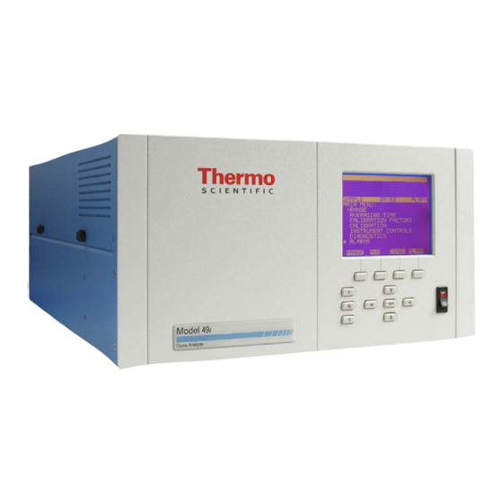
Thermo Scientific 49i Instruction Manual (314 pages)
UV Photometric O3 Analyzer
Brand:
Thermo Scientific
| Category:
Measuring Instruments
| Size: 13 MB
Table of Contents
Weee Compliance
3
Table of Contents
7
Chapter 1 Introduction
19
Introduction
23
Principle of Operation
24
Specifications
25
Ethernet Connection
25
Installation
27
Lifting
27
Unpacking and Inspection
27
Chapter 2 Installation
27
Remove the Packing Material
28
Setup Procedure
29
Connecting External Devices
31
Terminal Board PCB Assemblies
31
I/O Terminal Board Views
32
I/O Terminal Board Pin Descriptions
32
D/O Terminal Board Views
33
D/O Terminal Board Pin Descriptions
33
Startup
35
Operation
37
Chapter 3 Operation
37
Display
38
Pushbuttons
39
Front Panel Pushbuttons
39
Soft Keys
40
Software Overview
40
Power-Up Screen
42
Run Screen
42
Main Menu
43
Range Menu
44
Single Range Mode
44
Pin-Out of Rear Panel Connector in Single Range Mode
45
Default Analog Outputs in Single Range Mode
45
Dual Range Mode
46
Pin-Out of Rear Panel Connector in Dual Range Mode
46
Auto Range Mode
47
Default Analog Outputs in Dual Range Mode
47
Pin-Out of Rear Panel Connector in Auto Range Mode
49
Default Analog Outputs in Auto Range Mode
49
Gas Units
50
O3 Range
51
Set Custom Ranges
52
Averaging Time
53
Calibration Factors Menu
54
O 3 Background
54
O 3 Span Coefficient
56
Calibration Menu
57
Calibrate Zero
58
Calibrate O 3 Coefficient
58
Zero/Span Check
59
Instrument Controls Menu
63
Custom Levels
63
Pump
64
Ozonator Solenoid
65
Cycle Time
65
Temperature Compensation
66
Pressure Compensation
66
Datalogging Settings
67
Communication Settings
77
I/O Configuration
85
Screen Contrast
98
Service Mode
99
Date/Time
99
Diagnostics Menu
100
Program Version
100
Voltages
101
Temperatures
103
Pressure
103
Flows
103
Cell A/B O
104
Intensities
104
Analog Input Readings
105
Analog Input Voltages
105
Digital Inputs
105
Relay States
106
Test Analog Outputs
106
Instrument Configuration
107
Contact Information
108
Alarms Menu
108
O Lamp Temperature
109
Lamp Temperature
109
Bench Temperature
111
Pressure
112
Flow a and B
113
Intensity a and B
114
Zero and Span Check
115
Zero and Span Auto Calibration
116
Ozonator Level 1-5 Check
116
O Concentration
117
O 3 Concentration
118
Service Menu
119
Pressure Check
119
Lamp Setting
121
Detector Calibration
122
Intensity Check
122
Range Mode Select
123
Pressure Calibration
124
Flow a and B Calibration
126
Temperature Calibration
128
Analog Output Calibration
129
Analog Input Calibration
130
Dilution Ratio
132
Display Pixel Test
133
Restore User Defaults
133
Password Menu
133
Set Password
134
Lock Instrument
134
Change Password
135
Remove Password
135
Unlock Instrument
136
Calibration
137
Equipment Required
137
Zero Air Generator
137
Chapter 4 Calibration
137
Calibration Photometer System
138
Instrument Preparation
139
Calibration Photometer System Preparation
139
System Check
139
Model 49I Connected as Calibrator
139
Ozone Loss Test
140
Linearity Check
141
Intercomparability Test
143
Calibration Procedure
144
Connect Instrument
145
Zero Adjust
145
Model 49I Connected to Calibration Photometer
145
Span Adjust
146
Additional Concentration Standards
146
Calibration Curve
147
Periodic Zero and Span Checks
147
Internal Ozonator Adjustment (Option)
149
Chapter 5 Preventive Maintenance
151
Preventive Maintenance
152
Safety Precautions
152
Replacement Parts
152
Outside Case Cleaning
152
Optical Bench Cleaning
152
Lamp Replacement
153
Monitoring Detector Frequencies and Noise
154
Increasing Lamp Output
154
Monitoring Lamp Noise
154
Capillary Service
155
Pump Rebuilding
156
Leak Test and Pump Checkout
157
External Leaks
157
Solenoid Leaks
158
Solenoid Leak Test
159
Ozone Scrubber Test
160
Chapter 6 Troubleshooting
163
Safety Precautions
163
Troubleshooting Guides
164
Troubleshooting - General Guide
164
Troubleshooting - Alarm Messages
166
Board-Level Connection Diagrams
168
Board-Level Connection Diagram - Common Electronics
168
Board-Level Connection Diagram - Measurement System
169
Connector Pin Descriptions
170
Front Panel Board Connector Pin Diagram
175
I/O Expansion Board (Optional) Connector Pin Descriptions
177
Digital Output Board Connector Pin Descriptions
178
Measurement Interface Board Connector Pin Descriptions
179
Ozonator Power Supply Connector Pin Descriptions
181
Service Locations
183
Servicing
185
External Device Connection Components
185
Chapter 7 Servicing
185
Safety Precautions
187
Firmware Updates
188
Accessing the Service Mode
188
Replacement Parts List
188
Cable List
190
External Device Connection Components
190
Removing the Measurement Bench and Lowering the Partition Panel
192
Fuse Replacement
193
Pump Replacement
194
Fan Replacement
195
Analog Output Testing
196
Replacing a Fan
196
Analog Output Calibration
198
Analog Input Channels and Rear Panel Pin Connections
198
Analog Input Calibration
199
Calibrating the Input Channels to Zero Volts
199
Calibrating the Input Channels to Full Scale
200
I/O Expansion Board Replacement (Optional)
201
Digital Output Board Replacement
203
Motherboard Replacement
204
Measurement Interface Board Replacement
205
Front Panel Board Replacement
206
LCD Module Replacement
207
Optical Bench Replacement
208
Optical Bench Temperature Calibration
210
Photometer Lamp Replacement
211
Photometer Lamp Voltage Adjustment
212
Photometer Board Replacement
213
Detector Replacement
214
Ozone Scrubber Replacement
215
Sample/Reference Solenoid Replacement
216
Zero/Span Solenoid Replacement (Optional)
217
Pressure Transducer Replacement
217
Pressure Transducer Calibration
218
Flow Transducer Replacement
220
Flow Transducer Calibration
221
Ozonator Lamp Replacement (Optional)
222
Ozonator Lamp Heater Replacement (Optional)
224
Ozonator Replacement (Optional)
225
Ozonator Board Replacement (Optional)
225
Service Locations
226
System Description
227
Hardware
227
Ozonator Lamp Power Supply
227
Photometer Lamp Power Supply
227
Optical Bench Temperature Thermistor
227
Chapter 8 System Description
227
Software
229
Instrument Control
230
Monitoring Signals
230
Measurement Calculations
230
Output Communication
231
Electronics
231
Motherboard
231
Front Panel Display
231
Measurement Interface Board
232
Digital Output Board
233
I/O Expansion Board (Optional)
233
Front Panel Connector Board
234
I/O Components
234
Analog Voltage Outputs
234
Analog Current Outputs (Optional)
235
Analog Voltage Inputs (Optional)
235
Digital Relay Outputs
235
Digital Inputs
235
Serial Ports
236
RS-232 Connection
237
Ethernet Connection
238
External Accessory Connector
238
Internal Sample/Calibration
239
Zero Air Source
239
Chapter 9 Optional Equipment
239
Teflon Particulate Filter
240
I/O Expansion Board Assembly
240
Terminal Block and Cable Kits
240
Cables
240
Cable Options
241
25-Pin Terminal Board Assembly
242
Mounting Options
242
Mounting Options
243
Bench Mounting
244
Appendix A Warranty
247
Appendix B C-Link Protocol Commands
249
Instrument Identification Number
250
Entering Units in PPB
250
Accessing Streaming Data
250
Commands
250
C-Link Protocol Commands
251
Measurements
256
Averaging Times
257
Alarms
259
Diagnostics
264
Datalogging
265
Calibration
272
Keys/Display
274
Measurement Configuration
277
Range Settings
277
Hardware Configuration
281
Communications Configuration
283
Reply Termination Formats
286
I/O Configuration
287
Analog Current Output Range Values
288
Analog Voltage Output Range Values
288
Record Layout Definition
291
Format Specifier for ASCII Responses
292
Format Specifier for Binary Responses
292
Format Specifier for Front-Panel Layout
293
Appendix C MODBUS Protocol
297
Serial Communication Parameters
298
TCP Communication Parameters
298
Application Data Unit Definition
298
Slave Address
298
MBAP Header
298
Function Code
299
Data
299
Error Check
299
Function Codes
299
(0X01/0X02) Read Coils / Read Inputs
299
(0X03/0X04) Read Holding Registers / Read Input Registersc-5
301
(0X05) Force (Write) Single Coil
303
MODBUS Commands Supported
304
Appendix D Geysitech (Bayern-Hessen) Protocol
307
Serial Communication Parameters
307
TCP Communication Parameters
308
Instrument Address
308
Abbreviations Used
308
Basic Command Structure
308
Block Checksum <BCC
309
Geysitech Commands
309
Instrument Control Command (ST
309
Data Sampling/Data Query Command (da
310
Measurements Reported in Response to da Command for 49I and 49I PS
313
Operating and Error Status
313
Advertisement
Advertisement
Related Products
Thermo Scientific 49iQ
Thermo Scientific 410i
Thermo Scientific 48iQTL
Thermo Scientific 42iQ
Thermo Scientific Nicolet 4700
Thermo Scientific 42iQD
Thermo Scientific 43iQ
Thermo Scientific 410iQ
Thermo Scientific 450iQ
Thermo Scientific 495 Series
Thermo Scientific Categories
Laboratory Equipment
Measuring Instruments
Accessories
Freezer
Refrigerator
More Thermo Scientific Manuals
Login
Sign In
OR
Sign in with Facebook
Sign in with Google
Upload manual
Upload from disk
Upload from URL