Chapters
Table of Contents

Related Manuals for Keithley 6430


Summary of Contents for Keithley 6430
- Page 1 Test Equipment Depot - 800.517.8431 - 99 Washington Street Melrose, MA 02176 - TestEquipmentDepot.com Model 6430 Sub-Femtoamp Remote SourceMeter Instruction Manual A G R E A T E R M E A S U R E O F C O N F I D E N C E...
- Page 2 WARRANTY Keithley Instruments, Inc. warrants this product to be free from defects in material and workmanship for a period of 1 year from date of shipment. Keithley Instruments, Inc. warrants the following items for 90 days from the date of shipment: probes, cables, rechargeable batteries, diskettes, and documentation.
- Page 3 Model 6430 Sub-Femtoamp Remote SourceMeter Instruction Manual ©1999, Keithley Instruments, Inc. All rights reserved. Cleveland, Ohio, U.S.A. Fourth Printing, June 2001 Document Number: 6430-901-01 Rev. D...
- Page 4 Revision C (Document Number 6430-901-01) ............January 2000 Revision D (Document Number 6430-901-01) ............... June 2001 All Keithley product names are trademarks or registered trademarks of Keithley Instruments, Inc. Other brand names are trademarks or registered trademarks of their respective holders.
-
Page 5: Safety Precautions
Only properly trained service personnel may perform installation and service procedures. Keithley products are designed for use with electrical signals that are rated Installation Category I and Installation Category II, as described in the International Electrotechnical Commission (IEC) Standard IEC 60664. - Page 6 To maintain protection from electric shock and fire, replacement components in mains circuits, including the power transformer, test leads, and input jacks, must be purchased from Keithley Instruments. Standard fuses, with applicable national safety approvals, may be used if the rating and type are the same. Other components that are not safety related may be purchased from other suppliers as long as they are equivalent to the original component.
-
Page 7: Table Of Contents
Table of Contents Getting Started General information ..............Warranty information ............Contact information ............Manual addenda ..............Safety symbols and terms ........... Inspection ................Options and accessories ............Product overview ................ Mainframe and Remote PreAmp familiarization ....... Mainframe front panel summary ........Mainframe rear panel summary .......... - Page 8 Connections Connection overview ..............Connecting Remote PreAmp to the mainframe ....Source-measure terminals ........... Test fixture interlock ............Connections to DUT ..............Sensing methods ..............Guarding methods ..............Cable guard ................. Ohms guard ............... 2-10 Guard selection ..............2-13 Basic Source-Measure Operation CAUTION ..................
- Page 9 Ohms Measurements Ohms configuration menu ............Ohms measurement methods ............. Selecting ohms measurement method ......... Auto ohms measurements ........... Manual ohms measurements ..........Ohms sensing ................Offset-compensated ohms ............Measuring high resistance devices ........Enabling/disabling offset-compensated ohms ....Offset-compensated ohms procedure ........Ohms source readback ...............
- Page 10 Range, Digits, Speed, and Filters Range and digits ................. Range ................... Digits ................... Remote range and digits programming ....... Speed ..................Setting speed ............... Remote speed programming ..........Filters ..................Filter stages ................. Auto filter ................6-13 Filter configuration ............6-15 Filter control ..............
- Page 11 Sweep Operation Sweep types ................Linear staircase sweep ............Logarithmic staircase sweep ..........Custom sweep ..............Source memory sweep ............Configuring and running a sweep ..........9-11 Front panel sweep operation ..........9-11 Performing sweeps ............9-13 Remote sweep operation ........... 9-18 Triggering Trigger model (front panel operation) ........
- Page 12 Limit Testing Types of limits ................11-2 Pass/fail information ............11-2 Data flow ................11-3 Limit 1 test (compliance) ..........11-3 Limit 2, limit 3, and limit 5-12 tests ........11-3 Limit test modes ..............11-4 Binning ................11-4 Operation overview ..............11-4 Grading mode ..............
- Page 13 Remote Operations Differences: remote vs. local operation ........13-2 Operation enhancements (remote operation) ....13-2 Local-to-remote transition ..........13-2 Remote-to-local transition ..........13-3 Selecting an interface ............... 13-3 GPIB operation ................ 13-4 GPIB standards ..............13-4 GPIB connections ............. 13-4 Primary address ..............
- Page 14 Status Structure Overview .................. 14-2 Status byte and SRQ ............14-2 Status register sets ............. 14-2 Queues ................14-2 Clearing registers and queues ........... 14-4 Programming and reading registers .......... 14-5 Programming enable registers ........... 14-5 Reading registers .............. 14-6 Status byte and service request (SRQ) ........
- Page 15 SCPI Signal-Oriented Measurement Commands Command summary ..............16-2 Configuring measurement function .......... 16-2 :CONFigure:<function> ............ 16-2 Acquiring readings ..............16-3 :FETCh? ................16-3 [:SENSe[1]]:DATA[:LATest]? .......... 16-4 :READ? ................16-4 :MEASure[:<function>]? ..........16-5 SCPI Command Reference Reference tables ............... 17-2 Calculate subsystems ............. 17-22 CALCulate[1] .................
- Page 16 SENSe1 subsystem ..............17-54 Select measurement functions ......... 17-54 Select measurement range ..........17-57 Select auto range ............. 17-58 Set compliance limit ............17-59 Set measurement speed ........... 17-60 Configure and control filters ..........17-60 SOURce subsystem ..............17-64 SOURce[1] ..............17-64 Control source output-off ..........
- Page 17 Query timestamp ............. 17-97 Reset timestamp .............. 17-98 Auto reset timestamp ............17-98 Auto range change mode ..........17-98 :TRACe subsystem ..............17-99 Read and clear buffer ............17-99 Configure and control buffer ........... 17-99 Select timestamp format ..........17-101 TRIGger subsystem ..............
- Page 18 Remote PreAmp verification ..........18-17 Connecting Remote PreAmp to the mainframe ....18-17 Remote PreAmp output voltage accuracy ....... 18-18 Remote PreAmp voltage measurement accuracy .... 18-19 Remote PreAmp output current accuracy ....... 18-20 Remote PreAmp current measurement accuracy .... 18-24 Remote PreAmp resistance measurement accuracy ..
- Page 19 Specifications Accuracy calculations ............... Measure accuracy ............... Source accuracy ..............Source-Delay-Measure (SDM) cycle timing ......Definitions ................Timing diagrams ..............Status and Error Messages Introduction ................Status and error messages ............Eliminating common SCPI errors ..........Data Flow Introduction ................FETCh? ................
- Page 20 IEEE-488 and SCPI Conformance Information Introduction ................Measurement Considerations Floating measurement safety concerns ........Low current measurements ............Leakage currents and guarding .......... Noise and source impedance ..........Generated currents .............. Voltage burden ..............Overload protection ............F-10 High impedance voltage measurements ........F-10 Loading effects ..............
- Page 21 List of Illustrations Getting Started Figure 1-1 Front panel ................Figure 1-2 Model 6430 rear panel ............Figure 1-3 Remote preamp ..............1-10 Figure 1-4 Triax connectors ..............1-11 Figure 1-5 Main menu tree ..............1-23 Connections Figure 2-1 Basic input/output configurations ..........
- Page 22 Range, Digits, Speed, and Filters Figure 6-1 Speed configuration menu tree ..........Figure 6-2 3-stage filtering ............... Figure 6-3 Repeat filter (count 10) ............6-10 Figure 6-4 Median filter (rank 5) ............6-11 Figure 6-5 Moving filter (count 10) ............6-12 Figure 6-6 Configure filtering menu tree ..........
- Page 23 Figure 11-7 Binning system - single element devices ......11-12 Figure 11-8 Binning system - multiple element devices ....... 11-13 Figure 11-9 Digital output auto-clear timing example ......11-15 Figure 11-10 Limits configuration menu tree .......... 11-17 Figure 11-11 Diode pass/fail limits ............11-20 Digital I/O Port, Interlock, and Output Configuration Figure 12-1...
- Page 24 Performance Verification Figure 18-1 Test resistor construction ............18-5 Figure 18-2 Connections for mainframe voltage verification tests ..18-11 Figure 18-3 Connections for mainframe current verification tests ..18-13 Figure 18-4 Connections for mainframe resistance accuracy verification ..............18-15 Figure 18-5 Connections for Remote PreAmp voltage verification tests ............
- Page 25 IEEE-488 Bus Overview Figure D-1 IEEE-488 bus configuration ..........Figure D-2 IEEE-488 handshake sequence ..........Figure D-3 Command codes ..............D-11 Measurement Considerations Figure F-1 Floating measurements ............Figure F-2 Guarding an ionization chamber ..........Figure F-3 Voltage burden ............... Figure F-4 Overload protection for ammeter input .......
-
Page 27: List Of Tables
List of Tables Getting Started Table 1-1 Line frequency remote commands ........1-14 Table 1-2 Basic display commands ............1-16 Table 1-3 Factory default settings ............1-19 Table 1-4 Main menu ................1-21 Table 1-5 Measurement configuration menus ........1-27 Table 1-6 Source and range configuration menus ........ - Page 28 Range, Digits, Speed, and Filters Table 6-1 Model 6430 ranges ..............Table 6-2 Range and digits commands ........... Table 6-3 Range and digits programming example ........ Table 6-4 Speed commands ..............Table 6-5 Auto filter settings where NPLC = 0.01 to 0.10 ....
- Page 29 Digital I/O Port, Interlock, and Output Configuration Table 12-1 Digital output line settings ........... 12-5 Table 12-2 Output configuration commands .......... 12-9 Table 12-3 Output configuration programming example ..... 12-10 Remote Operations Table 13-1 General bus commands ............13-6 Table 13-2 PC serial port pinout ............
- Page 30 Performance Verification Table 18-1 Recommended verification equipment ......... 18-4 Table 18-2 Maximum compliance values ..........18-9 Table 18-3 Mainframe output voltage accuracy limits ......18-11 Table 18-4 Mainframe voltage measurement accuracy limits ....18-12 Table 18-5 Mainframe output current accuracy limits ......18-13 Table 18-6 Mainframe current measurement accuracy limits ....
- Page 31 IEEE-488 Bus Overview Table D-1 IEEE-488 bus command summary ........Table D-2 Hexadecimal and decimal command codes ......D-10 Table D-3 Typical addressed multiline command sequence ....D-12 Table D-4 Typical addressed common command sequence ....D-12 Table D-5 IEEE command groups ............D-13 Table D-6 SourceMeter interface function codes ........
-
Page 33: Getting Started
General Information — Covers general information that includes warranty informa- tion, contact information, safety symbols and terms, inspection, and available options and accessories. • Product Overview — Summarizes the features of the Model 6430 Sub-Femtoamp Remote SourceMeter. • Mainframe and Remote PreAmp Familiarization — Summarizes the controls and connectors on the mainframe and Remote PreAmp. -
Page 34: General Information
General information Warranty information Warranty information is located at the front of this manual. Should your Model 6430 require warranty service, contact the Keithley representative or authorized repair facility in your area for further information. When returning the instrument for repair, be sure to fill out and include the service form at the back of this manual to provide the repair facility with the necessary information. -
Page 35: Inspection
Model 6430. Triax cables and adapters (for Remote PreAmp) Model 6430-322-1A — This low-noise 8-inch cable is terminated with a 3-slot male triax connector on one end, and three booted alligator clips on the other end. Model 7078-TRX-1 — This low-noise 12-inch triax cable is terminated at both ends with 3-slot male triax connectors. - Page 36 Model 7078-TRX-BNC Adapter — This is a 3-slot male triax to female BNC adapter. This adapter lets you connect a BNC cable to the triax input of the Model 6430. Model 237-TRX-TBC Connector — This is a 3-lug female triax bulkhead connector with cap for assembly of custom panels and interface connections.
-
Page 37: Calibration Standards
19-inch rack. Model 4288-2 side-by-side rack mount kit — Mounts two instruments (Models 182, 428, 486, 487, 2000, 2001, 2002, 2010, 2015, 2400, 2410, 2420, 2430, 6430, 6517, 7001) side-by- side in a standard 19-inch rack. Model 4288-3 side-by-side rack mount kit — Mounts a SourceMeter and a Model 199 side-by-side in a standard 19-inch rack. -
Page 38: Product Overview
Programming language and remote interfaces — The SourceMeter uses the SCPI pro- gramming language and two remote interface ports (IEEE-488/GPIB and RS-232C). • Trigger-Link interface to Keithley Series 7000 switching hardware. • Math expressions — 5 built-in, up to 5 user-defined (bus only). -
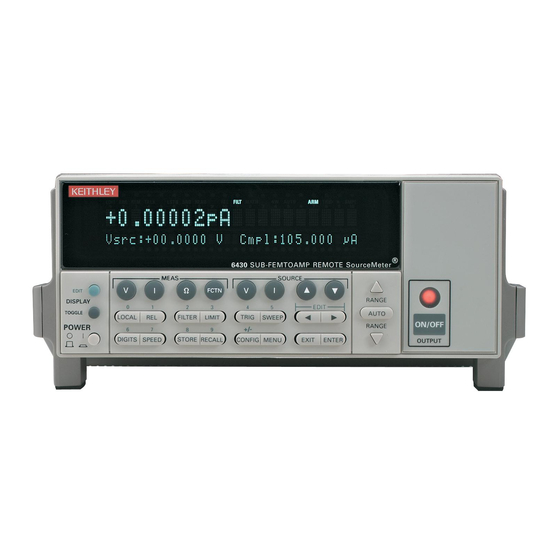
Page 39: Mainframe And Remote Preamp Familiarization
Mainframe rear panel summary — Provides an overview of rear panel connectors. • Remote PreAmp summary — Covers the Remote PreAmp connectors. Mainframe front panel summary The front panel of the Model 6430 is shown in Figure 1-1. Figure 1-1 Front panel ®... - Page 40 Getting Started Operation keys: EDIT Select source or compliance reading for editing. TOGGLE Toggle display positions of source and measure readings, or display V and I measurements. LOCAL Cancel remote operation. Enable/disable relative reading on present function. FILTER Display digital filter status for present function and toggle filter on/off. LIMIT Perform configured limit tests.
-
Page 41: Mainframe Rear Panel Summary
Getting Started Mainframe rear panel summary The rear panel of the Model 6430 is shown in Figure 1-2. Figure 1-2 WARNING: WARNING: NO INTERNAL OPERATOR SERVICABLE PARTS,SERVICE BY QUALIFIED PERSONNEL ONLY. NO INTERNAL OPERATOR SERVICABLE PARTS,SERVICE BY QUALIFIED PERSONNEL ONLY. -
Page 42: Remote Preamp Summary
8502, 8504. RS-232 connector: RS-232 Connector for RS-232 remote operation. Use a straight through (not null modem) DB-9 cable such as Keithley Model 7009-5. GPIB connector: IEEE-488 INTERFACE Connector for GPIB remote operation. Use a shielded cable (Model 7007-1 or 7007-2). - Page 43 Getting Started 1-11 Figure 1-4 Triax (4-Wire Sense High) (Input/Output High) connectors GUARD GUARD (Cable Guard) (Cable Guard) (Input/Output Low) (Input/Output Low) IN/OUT HIGH Triax Connector SENSE Triax Connector Preamp connector: MAINFRAME Connect the Remote PreAmp to the mainframe using the supplied preamp cable. Triax connectors: When using the Remote PreAmp, DO NOT use the INPUT/OUTPUT HI CAUTION...
-
Page 44: Power-Up
1-12 Getting Started Power-up WARNING To prevent electric shock, power must be off when connecting the Remote PreAmp to the mainframe. If you wish to connect the Remote PreAmp at this time, proceed to Section 2, Connecting Remote PreAmp to the mainframe. -
Page 45: Power-Up Sequence
ERR annunciator turns on. Error messages are listed in Appendix B. NOTE If a problem develops while the instrument is under warranty, return it to Keithley Instruments, Inc., for repair. If the instrument passes the self-tests, the firmware revision levels are displayed. For... -
Page 46: Fuse Replacement
Snap the fuse out of the drawer and replace it with the same type (250V, 2.5A, 5 × 20mm). The Keithley part number is FU-72. Push the fuse drawer back into the power module. -
Page 47: Display
Getting Started 1-15 Display Display format The SourceMeter display is used primarily to program source and compliance values and display measured readings. Annunciators, which are located along the top of the reading/ message display, indicate various states of operation, as covered previously in Front panel summary. -
Page 48: Status And Error Messages
1-16 Getting Started Status and error messages Status and error messages are displayed momentarily. During SourceMeter operation and programming, you will encounter a number of front panel messages. Typical messages are either status or error in nature and are listed in Appendix B. Remote display programming The display can also be controlled by various SCPI :DISPlay subsystem commands. -
Page 49: Default Settings
Getting Started 1-17 Front panel control Front panel display circuitry is controlled from the DISABLE DISPLAY configuration menu, which is accessed by pressing CONFIG and then EDIT (or TOGGLE). To select an option (NOW, NEVER, SWEEP, or STORE), use the keys to place the cursor on the desired option, then press ENTER. -
Page 50: Power-On Configuration
1-18 Getting Started Restoring setups Press the MENU key, select SAVESETUP, then press ENTER. From the SAVESETUP menu, select GLOBAL, then press ENTER. From the GLOBAL SETUP MENU, select RESTORE, then press ENTER. Select the setup position (0-4) to restore, then press ENTER to complete the process. Power-on configuration You can also define which of the stored setups (factory default or user) the instrument assumes as the power-on configuration as follows:... - Page 51 Getting Started 1-19 Table 1-3 Factory default settings Setting BENCH default GPIB default A/D Controls: Auto-zero Line frequency No effect No effect Beeper Data Store No effect No effect Digital output* 15 or 7 15 or 7 Digits FCTN Power (off) Power (off) Filter: Auto filter...
-
Page 52: Remote Setups
1-20 Getting Started Table 1-3 (cont.) Factory default settings Setting BENCH default GPIB default Power-on default No effect No effect Ranging (measure): Auto range Enabled Enabled Value RS-232 No effect No effect Source delay Auto-delay Disabled Disabled Speed Hi accuracy (10 PLC) Hi accuracy (10 PLC) Sweep Linear staircase... -
Page 53: Menus
Getting Started 1-21 Menus The following paragraphs discuss the main menu, configuration menus, and rules to navi- gate menus. Main menu Use the MENU key to access the Main Menu to select, configure, and/or perform various instrument operations. These include default setup conditions, communications (GPIB or RS-232), calibration, front panel tests, digital output states, auto zero and NPLC caching, timestamp, numeric display format, and the beeper. - Page 54 1-22 Getting Started Table 1-4 (cont.) Main menu Menu item Description Parameters Calibrate SourceMeter. (See Section 19.) TEST Perform tests on SourceMeter. DISPLAY TESTS Test front panel keys and display digits. KEYS Test front panel keys. DISPLAY PATTERNS Test display pixels and annunciators. CHAR SET Test special display characters.
-
Page 55: Getting Started
Getting Started 1-23 Figure 1-5 Press MENU key (Use to select item, then press ENTER) Main menu tree SAVESETUP GLOBAL SAVE RESTORE POWERON BENCH GPIB USER-SETUP-NUMBER RESET SOURCE MEMORY SAVE RESTORE COMMUNICATION GPIB RS-232 BAUD BITS PARITY TERMINATOR FLOW-CTRL CAL* UNLOCK EXECUTE VIEW-DATES... -
Page 56: Rules To Navigate Menus
1-24 Getting Started Rules to navigate menus Many source-measure functions and operations are configured from the front panel menus. Use the following rules to navigate through these configuration menus: NOTE Rules to edit source and compliance values are found in Section 3, “Basic source- measure procedure.”... -
Page 57: Editing Source And Compliance Values
Getting Started 1-25 Editing source and compliance values Use the following keys to edit source and compliance values: • EDIT: selects the source or compliance display field for editing. A blinking cursor will appear in the field to be edited. If no key is pressed within a few seconds, the edit mode will be cancelled automatically. -
Page 58: Configuration Menus
1-26 Getting Started Configuration menus There are a number of configuration menus that can be accessed by pressing the CONFIG key followed by the appropriate function or mode key. For example, you can configure the volt- age source by pressing CONFIG then SOURCE V. Configuration menus, which are summa- rized in Table 1-5 through Table 1-10, are available for the following operating modes: •... - Page 59 Getting Started 1-27 Table 1-5 Measurement configuration menus Configuration menu item Description CONFIG MEAS Ω Configure ohms measure. CONFIG OHMS SOURCE Select manual or auto source for ohms. MANUAL AUTO GUARD Select ohms or cable guard. OHMS CABLE SRC RDBK Enable/disable source readback.
-
Page 60: Figure
1-28 Getting Started Table 1-6 Source and range configuration menus Configuration menu item Description CONFIG SOURCE V Configure V source. CONFIGURE V SOURCE PROTECTION Select voltage protection. DELAY Program delay between source and measure. AUTO DELAY Enable/disable auto delay. DISABLE ENABLE GUARD Select ohms or cable guarding. -
Page 61: Figure
Getting Started 1-29 Table 1-7 Rel, filter, and limit configuration menus Configuration menu item Description CONFIG REL Program REL value. CONFIG FILTER Configure filter. AUTO FILTER Enable/disable auto filter. DISABLE ENABLE CONFIG LIMIT Configure limit tests. CONFIGURE LIMITS MENU DIGOUT Program Digital I/O bit patterns for pass/fail. -
Page 62: Figure
1-30 Getting Started Table 1-8 Trigger configuration menu Configuration menu item Description CONFIG TRIG Configure triggering. CONFIGURE TRIGGER ARM LAYER Configure trigger model arm layer. ARM IN Select arm layer detection event. IMMEDIATE Immediate event detection. GPIB GPIB GET or *TRG. TIMER After timer interval elapses, enter interval. -
Page 63: Figure
Getting Started 1-31 Table 1-9 Sweep, digits, speed, and data store configuration menus Configuration menu item Description CONFIG SWEEP Configure sweeps. CONFIGURE SWEEPS TYPE Select sweep type. STAIR Staircase sweep, program START, STOP, STEP. Log sweep, program START, STOP, # POINTS. CUSTOM Custom sweep, program parameters. - Page 64 1-32 Getting Started Table 1-10 Output and display configuration menus Configuration menu item Description CONFIG ON/OFF OUTPUT Configure output. CONFIGURE OUTPUT OFF STATE Set up output off state. NORMAL Normal off state. ZERO Zero off state. GUARD Guard mode off state. AUTO OFF Enable disable auto off mode.
-
Page 65: Connections
Connections • Connection Overview — Explains how to connect the Remote PreAmp to the main- frame, provides basic information on the input/output connectors, and discusses using a test fixture interlock. • Connections to DUT — Covers various methods for making connections to the DUT, including 4-wire remote sensing, 2-wire local sensing, cable and ohms guard, as well as guard selection. -
Page 66: Connection Overview
Connections Connection overview WARNING To prevent electric shock, test connections must be configured such that the user cannot come in contact with conductors or any DUT that is in contact with the conductors. Safe installation requires proper shields, bar- riers, and grounding to prevent contact with conductors. Operator protec- tion and safety are the responsibility of the person installing the product. -
Page 67: Source-Measure Terminals
Connections At the rear panel of the mainframe, remove the plastic safety cover from the preamp connector. This connector is labeled “REMOTE PreAmp.” The plastic cover is secured to the connector with two screws. Hold on to the plastic cover and the retaining screws. Whenever the Remote PreAmp is not being used, the plastic safety cover must be re- installed on the mainframe preamp connector. -
Page 68: Figure 2-1 Basic Input/Output Configurations
The outer shield (shell) of each triax connector is input/output LO. NOTE The 6430-322-1A triax cable (which is a supplied accessory) is terminated with a triax connector on one end and booted alligator clips on the other end. (See Figure 2-1B.) When connected to the Remote PreAmp, the alligator clip with the red boot is... -
Page 69: Test Fixture Interlock
Connections Input/output LO and chassis ground Input/Output LO is not directly connected to chassis ground. For test circuits that require Input/Output LO connected to chassis ground, you can use the supplied chassis ground plug. Connect the lug end of the cable to the chassis ground screw on the rear panel of the main- frame, and plug the other end into the INPUT/OUTPUT LO banana jack. -
Page 70: Connections To Dut
Sensing methods Basic source-measure operations are performed using either 2-wire sense connections (Figure 2-2) or 4-wire sense connections (Figure 2-3). See Section 4, Ohms sensing for additional information. Figure 2-2 *Keithley part number: CA-176-1D. Noise Shield Two-wire KEITHLEY Triax Cable... -
Page 71: Figure
Connections Figure 2-3 Noise Shield *Keithley part number: CA-176-1D. Four-wire sense connections Triax Cable KEITHLEY Preamp Cable* 6430 Triax REMOTE Cable Sense PreAmp Sense HI WARNING Guard is at the same voltage level as input/output high. Therefore, if a hazardous voltage (≥42V peak) is... - Page 72 • There is no hardware configurations needed to enable 4-wire sense. Simply hook up the sense wires; otherwise, the Model 6430 will sense the voltage locally through resistors. • Specified accuracies for both source and measure are only achieved using 4-wire sensing.
-
Page 73: Guarding Methods
Connections • The Model 6430 will perform to rated specification with up to 1V drop per source lead on the 100µA through 100mA ranges. On the 10µA range and belo w (when using the Remote PreAmp), the allowable voltage drop in each source lead is limited as follows:... -
Page 74: Figure 2-5 Guarded Ohms Connections (Basic)
Remote PreAmp and mainframe. ≥1kΩ Banana Plug Cable 6430 Mainframe (rear panel connectors) WARNING: WARNING: NO INTERNAL OPERATOR SERVICABLE PARTS,SERVICE BY QUALIFIED PERSONNEL ONLY. NO INTERNAL OPERATOR SERVICABLE PARTS,SERVICE BY QUALIFIED PERSONNEL ONLY. -
Page 75: Figure 2-6 Guarded Ohms Connections (Guard Sense)
Remote PreAmp and mainframe. <1kΩ Banana Plug Cables 6430 Mainframe (rear panel connectors) WARNING: WARNING: NO INTERNAL OPERATOR SERVICABLE PARTS,SERVICE BY QUALIFIED PERSONNEL ONLY. NO INTERNAL OPERATOR SERVICABLE PARTS,SERVICE BY QUALIFIED PERSONNEL ONLY. -
Page 76: Figure 2-7 Guarded Ohms Connections (6-Wire Ohms)
Remote PreAmp and mainframe. <1kΩ Sense HI Banana Plug Cables <1kΩ Sense LO 6430 Mainframe (rear panel connectors) WARNING: WARNING: NO INTERNAL OPERATOR SERVICABLE PARTS,SERVICE BY QUALIFIED PERSONNEL ONLY. NO INTERNAL OPERATOR SERVICABLE PARTS,SERVICE BY QUALIFIED PERSONNEL ONLY. MADE IN V, Ω,... -
Page 77: Guard Selection
Connections 2-13 Guard selection Cable guard is used for high-impedance guarding for cables (i.e., coax and triax) and test fixtures. Ohms guard provides a high-current guard output, which allows in-circuit guarded ohms measurements. The guard setting (cable or ohms) only applies to mainframe guard (V,Ω GUARD banana jack). - Page 78 2-14 Connections...
- Page 79 Basic Source-Measure Operation Operation Overview — Discusses source-measure capabilities, compliance limit, and • fundamental source-measure configuration. Operation Considerations — Covers warm-up, auto zero, V-source protection, and • source delay. Basic Source-Measure Procedure — Describes the basic procedure for setting up the •...
-
Page 80: Basic Source-Measure Operation
Basic Source-Measure Operation CAUTION Excessive heat could damage the SourceMeter and at the very least, degrade its perfor- mance. The SourceMeter must be operated in an environment where the ambient temperature does not exceed 50°C. The SourceMeter uses a heat sink to dissipate heat. The left side of the case is cut out to expose the black, finned heat sink. -
Page 81: Operation Overview
Basic Source-Measure Operation Operation overview Source-measure capabilities From the front panel, the SourceMeter can be configured to perform the following operations: Source voltage — Display current and/or voltage measurement • Source current — Display voltage and/or current measurement • Measure resistance — Display voltage or current component of measurement •... -
Page 82: Compliance Limit
Basic Source-Measure Operation NOT E Load regulation – The voltage specification for V-source mode load changes is 0.01% +100µV. This means that on the 200mV range, the load current can be changed from zero to full scale with less than 1.02mV of error. Calculation: error = (0.01% ×... -
Page 83: Setting The Compliance Limit
Basic Source-Measure Operation Setting the compliance limit Front panel compliance limit Set the compliance limit from the front panel as follows: Select the desired source and measure functions using the MEAS and SOURCE keys. Press the EDIT key until the cursor flashes in the compliance (Compl:) display field. Select the desired compliance range using the RANGE keys. -
Page 84: Auto Zero
Basic Source-Measure Operation Basic circuit configuration The fundamental source-measure configuration for the SourceMeter (with Remote PreAmp) is shown in Figure 3-1, where the Source is either the V-Source or the I-Source. If not using the Remote PreAmp, Input/Output HI and LO is accessed at the rear panel of the mainframe. NOT E When using the Remote PreAmp, nothing should be connected to INPUT/OUTPUT HI banana jack on the mainframe. -
Page 85: Nplc Caching
Basic Source-Measure Operation Temperature changes across components within the instrument can cause the reference and zero values for the A/D converter to drift due to thermo-electric effects. Auto zero acts to negate the effects of drift in order to maintain measurement accuracy over time. Without auto zero enabled, measurements can drift and become erroneous. -
Page 86: V-Source Protection
Basic Source-Measure Operation NPLC cache setup Follow the steps below to enable and use NPLC caching with a source memory sweep: Press the MENU key, select A/D-CTRL, then press ENTER. Select AUTO-ZERO, then press ENTER. Choose DISABLE, then press ENTER to disable auto zero. From the A/D CONTROLS menu, select NPLC-CACHE, then press ENTER. -
Page 87: Source Delay
Basic Source-Measure Operation Front panel V-source protection To program V-source protection from the front panel: Press CONFIG then SOURCE V. Select PROTECTION from the displayed choices, then press ENTER. Select the desired protection value, then press ENTER. Press EXIT to return to normal display. Remote command V-source protection Use the :SOURce:VOLTage:PROTection command to program the V-source protection value via remote. -
Page 88: Basic Source-Measure Procedure
3-10 Basic Source-Measure Operation Front panel source delay To set the manual source delay from the front panel: Press CONFIG then SOURCE V (or SOURCE I). Select DELAY from the displayed choices, then press ENTER. Enter the desired DELAY value, then press ENTER. Press EXIT to return to normal display. -
Page 89: Current Measurements And Capacitive Loads
The higher the capacitance, the more ringing that will occur. Table 3-5 lists the maximum capacitive loads that the Model 6430 can accommodate effec- tively. For the higher current ranges (1nA range and higher), the listed values represent the larg- est capacitance in which ringing created by a voltage step will decay in less than one power line cycle. -
Page 90: Front Panel Source-Measure Procedure
3-12 Basic Source-Measure Operation Front panel source-measure procedure Refer to Section 4 to measure ohms. NOT E The following procedure assumes that the SourceMeter is already connected to the DUT as explained in Section 2. Step 1: Select source. Press SOURCE V to select the V-Source or press SOURCE I to select the I-Source. The presently programmed source value (V or I ) and compliance level (Cmpl) are... - Page 91 Basic Source-Measure Operation 3-13 Perform the following steps to edit the source and compliance values: Press EDIT to enter the edit mode. The flashing digit indicates which reading (source or compliance) is presently selected for editing. If you wish to edit the other field, press EDIT again.
- Page 92 3-14 Basic Source-Measure Operation Measuring voltage — When sourcing current, you can use the RANGE keys to ▲ ▼ manually select the voltage measurement range. You can also press AUTO to select autorang- ing. When sourcing voltage, the RANGE keys are inoperative. Measuring current —...
-
Page 93: Remote Command Source-Measure Procedure
Basic Source-Measure Operation 3-15 Remote command source-measure procedure Basic source-measurement procedures can also be performed via remote by sending appro- priate commands in the right sequence. The following paragraphs summarize the basic com- mands and give a simple programming example. Basic source-measure commands Table 3-6 summarizes basic source-measure commands. - Page 94 3-16 Basic Source-Measure Operation Source-measure programming example Table 3-7 summarizes the command sequence for a basic source-measure procedure. Note that the steps correspond to those listed previously in Front panel source-measure procedure. These commands set up the SourceMeter as follows: •...
- Page 95 Basic Source-Measure Operation 3-17 Measure only Front panel measure only In addition to being used for conventional source-measure operations, the SourceMeter can also be used to measure only voltage or current. Perform the following steps to use the SourceMeter to measure voltage or current: Select source-measure functions.
-
Page 96: Remote Command Measure Only
3-18 Basic Source-Measure Operation Remote command measure only Table 3-8 summarizes the basic command sequence for measure only. The steps outlined correspond to those in the Front panel measure only sequence above. These commands set up the SourceMeter for measure only voltage measurements up to 20V as follows: •... -
Page 97: Sink Operation
Basic Source-Measure Operation 3-19 Sink operation Overview When operating as a sink (V and I have opposite polarity), the SourceMeter is dissipating power rather than sourcing it. An external source (i.e., battery) or an energy storage device (i.e., capacitor) can force operation into the sink region. For example, if a 12V battery is connected to the V-Source (In/Out HI to battery high) that is programmed for +10V, sink operation will occur in the second quadrant (Source +V and measure -I). - Page 98 3-20 Basic Source-Measure Operation...
-
Page 99: Ohms Measurements
Ohms Measurements • Ohms Configuration Menu — Outlines the ohms configuration menu that allows you to set up various ohms measurement aspects. • Ohms Measurement Methods — Discusses auto and manual ohms measurement methods and how to select them. • Ohms Sensing —... -
Page 100: Figure 4-1 Ohms Configuration
Ohms Measurements Ohms configuration menu Press CONFIG then Ω to access the ohms configuration menu. Use the Rules to navigate menus in Section 1 to select the various items in the menu tree, which is shown in Figure 4-1. Menu items include: SOURCE —... -
Page 101: Ohms Measurement Methods
Ohms Measurements Ohms measurement methods There are two methods to measure ohms: auto ohms and manual ohms. When using auto ohms, the SourceMeter operates as a conventional constant current source ohmmeter. To use this method, simply select an ohms measurement range (or use autorange), and take the reading from the display. -
Page 102: Selecting Ohms Measurement Method
Ohms Measurements Selecting ohms measurement method On power-up, auto ohms is the default method for the ohms function. Perform the following steps to check and/or change the ohms measurement method: Press CONFIG and then Ω to display the ohms configuration menu. Using left and right arrow EDIT keys, place the cursor (flashing menu item) on SOURCE and press ENTER. -
Page 103: Manual Ohms Measurements
Ohms Measurements Select measurement range. Use the RANGE keys to select a range appropriate for the expected ohms ▲ ▼ reading, or use autorange by pressing AUTO. When using manual ranging, selecting the most sensitive (lowest) range provides the best accuracy. Autorange automatically goes to the most sensitive range. -
Page 104: Ohms Sensing
Ohms Measurements Select measurement range. Using the RANGE keys, select the lowest possible fixed range or use AUTO ▲ ▼ range. Note that if sourcing current, you will be setting the voltage measurement range. Conversely, if sourcing voltage, you will be setting the current measurement range. The most sensitive measurement range provides the best accuracy. -
Page 105: Offset-Compensated Ohms
Ohms Measurements Offset-compensated ohms The presence of thermal EMFs (V ) can adversely affect low-resistance measurement accuracy. To overcome these unwanted offset voltages, use the offset-compensated ohms mea- surement method. In general, this method measures resistance (V/I) at a specific source level and then subtracts a resistance measurement made with the source set to zero. -
Page 106: Enabling/Disabling Offset-Compensated Ohms
Ohms Measurements Enabling/disabling offset-compensated ohms Offset-compensated ohms is enabled or disabled from the OFFSET COMPENSATION option of the CONFIG OHMS menu as follows: Press CONFIG and then Ω to display the ohms configuration menu. Place the cursor on OFFSET COMPENSATION, and press ENTER. Place the cursor over ON (to enable compensation) or OFF (to disable compensation), and press ENTER. -
Page 107: Ohms Source Readback
Ohms Measurements Ohms source readback With ohms source readback enabled, the instrument measures the actual source value used for ohms measurements and then uses that measured value for reading calculations. Normally, ohms source readback should be left enabled for optimum measurement accuracy. However, disabling source readback will allow you to make valid ohms measurements with the source in compliance. -
Page 108: Remote Ohms Programming
4-10 Ohms Measurements Remote ohms programming The following paragraphs summarize those basic command necessary for remote ohms pro- gramming and also give a programming example for a typical ohms measurement situation. Remote ohms commands Table 4-2 summarizes the remote commands for making basic ohms measurements. See Section 17 for more details on these commands. -
Page 109: Source-Measure Concepts
Source-Measure Concepts • Compliance Limit — Discusses compliance limit including real and range compli- ances, maximum compliance values, and how to determine compliance limit. • Overheating Protection — Explains how to keep the SourceMeter from overheating. • Source-Delay-Measure Cycle — Describes the various phases of the source-delay- measure cycle as well as sweep waveforms. -
Page 110: Compliance Limit
Source-Measure Concepts Compliance limit When sourcing voltage, the SourceMeter can be set to limit current (from 1fA to 105mA). Conversely, when sourcing current, the SourceMeter can be set to limit voltage (from 200µV to 210V). The SourceMeter output will not exceed the compliance limit. NOTE For the following discussion, “measurement range”... -
Page 111: Maximum Compliance Values
Source-Measure Concepts Maximum compliance values The maximum compliance values for the measurement ranges are summarized in Table 5-1. Table 5-1 Maximum compliance values Measurement Maximum compliance range value 200mV 210mV 2.1V 200V 210V 1pA* 1.05pA 10pA* 10.5pA 100pA* 105pA 1nA* 1.05nA 10nA* 10.5nA... -
Page 112: Compliance Principles
Source-Measure Concepts Compliance principles Compliance acts as a clamp. If the output reaches the compliance value, the SourceMeter will attempt to prevent the output from exceeding that value. This action implies that the source will switch from a V-source to an I-source (or from an I-source to a V-source) when in compli- ance. -
Page 113: Overheating Protection
Source-Measure Concepts Table 5-2 Compliance examples Compliance setting Measurement range Actual compliance Display message Setting Display message Range Value Type Cmpl: 150.000 V 150V ---.---V 200V 150V Real Cmpl: 150.000 V 150V --.----V Range Cmpl: 150.000 V 150V ---.---mV 200mV 210mV Range Cmpl: 075.000 mA... - Page 114 Source-Measure Concepts Source-delay-measure cycle In addition to static source and/or measure operation, SourceMeter operation can consist of a series of source-delay-measure (SDM) cycles (Figure 5-1). During each SDM cycle, the fol- lowing occurs: Set the source output level. Wait for the delay. Make the measurement.
-
Page 115: Figure 5-2 Simplified Trigger Model
Source-Measure Concepts The manually set delay (up to 9999.999 sec) is available to compensate for longer settling required by external circuitry. The more capacitance seen at the output, the more settling time is required for the source. The actual delay period needed can be calculated or determined by trial and error. -
Page 116: Figure 5-3 Three Basic Sweep Waveform Types
Source-Measure Concepts Sweep waveforms There are four basic sweep types to select from: linear staircase, logarithmic staircase, cus- tom, and source memory. Three of the sweeps are shown in Figure 5-3. The linear staircase sweep goes from the start level to the stop level in equal linear steps. The logarithmic staircase sweep is similar except it is done on a log scale with a specified number of steps per decade. -
Page 117: Operating Boundaries
Source-Measure Concepts Typical applications for staircase sweeps include: I-V curves for two- and three-terminal semiconductor devices, characterization of leakage versus voltage, and semiconductor break- down. Pulse sweeps are used in applications where thermal response is measured or where sus- tained power levels can damage the external Device Under Test (DUT). Source memory sweeps are used in applications where multiple source-measure functions and/or math expres- sions are required. -
Page 118: Figure 5-4 Operating Boundaries
5-10 Source-Measure Concepts The general operating boundaries for the SourceMeter are shown in Figure 5-4. In this draw- ing, the 100mA, 20V and 10mA, 200V magnitudes are nominal values. The actual maximum output magnitudes of the SourceMeter are 105mA, 21V and 10.5mA, 210V. Also note that the boundaries are not drawn to scale. - Page 119 Source-Measure Concepts 5-11 Figure 5-5 Limit I-Source boundaries 210V Source 105mA 10.5mA A) Output Characteristics Voltage Compliance Limit Line V Measure Current Source Limit Line I Source B) Limit Lines...
- Page 120 5-12 Source-Measure Concepts Where within the boundaries the SourceMeter operates depends on the load (DUT) that is connected to its output. Figure 5-6 shows operation examples for resistive loads that are 50Ω and 200Ω, respectively. For these examples, the SourceMeter is programmed to source 100mA and limit 10V.
-
Page 121: Figure 5-6 I-Source Operating Boundaries
Source-Measure Concepts 5-13 Voltage Limit Figure 5-6 Load Line I-Source operating boundaries V-Meter Operating Point Current Source Load Line 100mA I-Source (I V-Meter = I • R = (100mA) (50Ω) = 5V A) Normal I-source operation Voltage Limit Operating Load Line Point V-Meter Current Source... -
Page 122: V-Source Operating Boundaries
5-14 Source-Measure Concepts V-Source operating boundaries Figure 5-7 shows the operating boundaries for the V-Source. Only the first quadrant of oper- ation is covered. Operation in the other three quadrants is similar. Figure 5-7A shows the output characteristics for the V-Source. As shown, the SourceMeter can output up to 21V at 105mA, or 210V at 10.5mA. -
Page 123: Figure 5-7 V-Source Boundaries
Source-Measure Concepts 5-15 Figure 5-7 Limit I V-Source boundaries 105mA 10.5mA Source 210V A) Output characteristics Current Compliance Limit Line I Measure Voltage Source Limit Line V Source B) Limit lines... - Page 124 5-16 Source-Measure Concepts Where within the boundaries the SourceMeter operates depends on the load (DUT) that is connected to the output. Figure 5-8 shows operation examples for resistive loads that are 2kΩ and 800Ω, respectively. For these examples, the SourceMeter is programmed to source 10V and limit 10mA.
- Page 125 Source-Measure Concepts 5-17 Figure 5-8 Current Limit Load Line V-Source operating examples 10mA I-Meter Operating Point Voltage Source Load Line V-Source (V = 10V/2kΩ = 5mA A) Normal V-source operation Current Limit Operating Load Line Point 10mA I-Meter Voltage Source Load Line 100V V-Source (V...
-
Page 126: Source I Measure I And Source V Measure V
5-18 Source-Measure Concepts Source I measure I and source V measure V The SourceMeter can measure the function it is sourcing. When sourcing a voltage, you can measure voltage. Conversely, if you are sourcing current, you can measure the output current. For these measure source operations, the measure range is the same as the source range. - Page 127 Source-Measure Concepts 5-19 Figure 5-9 GUARD SENSE Mainframe Source I V,Ω Guard Cable Guard Guard IN/OUT HIGH Local I-Meter HI (Input/Output) Guard (Cable) LO (Input/Output) Remote SENSE Preamp HI (Sense) V-Meter REMOTE I-Source Guard (Cable) PreAmp LO (Input/Output) Remote 4-WIRE SENSE LO Local INPUT/OUTPUT LO...
-
Page 128: Figure 5-10 Source V
5-20 Source-Measure Concepts Source V When configured to source voltage (V-Source) as shown in Figure 5-10, the SourceMeter functions as a low-impedance voltage source with current limit capability and can measure cur- rent (I-Meter) or voltage (V-Meter). Sense circuitry is used to continuously monitor the output voltage and make adjustments to the V-Source as needed. -
Page 129: Figure 5-11 Measure-Only (V Or I)
If the Remote PreAmp is not used, use the INPUT/OUTPUT H1 and LO terminals on the mainframe. Note however, that when not using the Remote PreAmp, the 100nA through 1pA current ranges are not available. Figure 5-11 6430 Sense Selection: 2-wire Measure-only (V or I) I-Source... -
Page 130: Guard
5-22 Source-Measure Concepts Guard Guard is at the same potential as input/output HI. Thus, if hazardous WARNING voltages are present at input/output HI, they are also present at the guard terminals. The driven guard is always enabled and provides a buffered voltage that is at the same level as the input/output HI (or sense HI for remote sense) voltage. -
Page 131: Figure 5-12 High-Impedance Measurements
When using shielded, triaxial, or coaxial cabling with guard, cable guard (not ohms guard) must be used to prevent oscillations. CABLE guard is the factory default setting. Figure 5-12 Insulator Insulator High-impedance IN/OUT HIGH 6430 HI (In/Out) measurements In/Out HI I-Meter Guard (Cable) LO (In/Out) Guard... -
Page 132: Figure 5-13 In-Circuit Ohms Measurements
(I ) from the SourceMeter will flow through R . The voltage across R then measured, and an accurate resistance measurement is calculated, in this case 20kΩ. Figure 5-13 6430 V,Ω GUARD (Ohms Guard) Guard In-circuit ohms measurements... - Page 133 For 6-wire ohms guard measurements, configure the output-off state to the GUARD mode. For details on the GUARD output-off state, see Section 12, “Output configuration.” Figure 5-14 Test Lead Resistance V,Ω GUARD In-circuit ohms 6430 (Ohms Guard) Guard measurements 1Ω using guard sense IN/OUT HIGH...
-
Page 134: Data Flow
5-26 Source-Measure Concepts Data flow Data flow for front panel operation is summarized by the block diagrams provided in Figure 5-15. Note that if REL is enabled, the result of the rel operation is sent to the other blocks. NOTE See Appendix C for remote operation data flow information. -
Page 135: Figure 5-15 Data Flow Front Panel
Source-Measure Concepts 5-27 Figure 5-15 Data Measurement Display Buffer and Data flow front V, I, Ω Store Conversions Statistics Readings panel Display Readings A. Math (FCTN) and limit tests disabled Display Buffer and Measurement Data V, I, Ω Statistics Readings Conversions Store Math (FCTN) -
Page 136: Buffer Considerations
5-28 Source-Measure Concepts Buffer considerations When the SourceMeter is in the process of storing readings, configuration changes affect what gets stored in the buffer. These storage considerations and restrictions are summarized in Table 5-3. Table 5-3 Buffer considerations What happens if the basic measure- What happens if What happens if... - Page 137 Source-Measure Concepts 5-29 Changing MATH function • If you started with only a basic measurement function selected, you can enable a MATH function, but only the voltage, current, or resistance component of the calcula- tion will be stored in the buffer. The results of the MATH function will not be stored. •...
- Page 138 5-30 Source-Measure Concepts...
-
Page 139: Range, Digits, Speed, And Filters
Range, Digits, Speed, and Filters • Range and Digits — Discusses available ranges, maximum readings, ranging limita- tions, manual and autoranging, and display resolution. • Speed — Discusses speed settings, which are used to control the integration period of the A/D converter. •... -
Page 140: Table 6-1 Model 6430 Ranges
Remote PreAmp. However, when not using the Remote PreAmp, the lower current ranges and higher resistance ranges are not available. Table 6-1 lists the available ranges for the SourceMeter. Table 6-1 Model 6430 ranges Voltage Ranges Current Ranges Ohms Ranges... -
Page 141: Maximum Readings
Range, Digits, Speed, and Filters Maximum readings The full scale input for each voltage and current measurement range is 105.5% of the selected range. For example, ±2.11V is the full scale reading for the 2V range, ±105.5mA is the full scale reading for the 100mA range. The full scale reading for auto ohms is 110% of the selected ohms measurement range. -
Page 142: Auto Ranging
Range, Digits, Speed, and Filters Auto ranging For the Source V Measure I, Source I Measure V, and Ohms configurations, press AUTO RANGE to enable auto ranging. The AUTO annunciator turns on when auto ranging is selected. With auto ranging selected, the instrument automatically chooses the best range to measure the applied signal. -
Page 143: Digits
Range, Digits, Speed, and Filters Auto range limits Auto range limits are included to support the auto range change mode. For voltage and cur- rent, the upper limit is controlled by the compliance range and cannot be programmed. For the auto ohms mode, however, the upper limit is adjustable. -
Page 144: Remote Range And Digits Programming
Range, Digits, Speed, and Filters Remote range and digits programming Table 6-2 summarizes the commands necessary to control range and digits. See Section 17 for more details on these commands. Table 6-2 Range and digits commands Commands Description :SENSe:CURRent:RANGe <n> Select manual amps range (n = range). -
Page 145: Speed
Range, Digits, Speed, and Filters Range and digits programming example Table 6-3 shows a programming example for controlling range and digits. The SourceMeter is set up as follows: • Source function: volts • Source level: 10V • Measure function: amps •... -
Page 146: Figure 6-1 Speed Configuration Menu Tree
Range, Digits, Speed, and Filters SPEED-ACCURACY MENU Press SPEED or CONFIG SPEED to display the menu. • FAST — Sets speed to 0.01 PLC and sets display resolution to 3 digits. MED — Sets speed to 0.10 PLC and sets display resolution to 4 •... -
Page 147: Figure 6-2 3-Stage Filtering
Range, Digits, Speed, and Filters Filters Filtering stabilizes noisy measurements caused by noisy input signals. However, the more filtering that is used, the slower the measurement process becomes. The SourceMeter uses three stages of filtering; repeat, median, and moving. The displayed, stored, or transmitted reading is simply the result of the filtering processes. -
Page 148: Figure 6-3 Repeat Filter (Count 10)
6-10 Range, Digits, Speed, and Filters Repeat filter The Repeat Filter places the specified number of measurement conversions into a stack and averages them to yield a single Repeat Filter reading. The stack is then cleared, and the process starts over. For example, if the repeat count (stack size) is 10, every 10 measurement conver- sions will yield a single reading. -
Page 149: Figure 6-4 Median Filter (Rank 5)
Range, Digits, Speed, and Filters 6-11 From the above equation, it can be seen that the minimum number of sample readings is 1 (n=0) and the maximum number is 11 (n=5). The following table shows the number of sample readings for each rank setting. Rank # of Sample setting... - Page 150 6-12 Range, Digits, Speed, and Filters Moving filter The moving average filter uses a first-in, first-out stack. When the stack (filter count) becomes full, the readings are averaged, yielding a filtered reading. For each subsequent read- ing placed into the stack, the oldest reading is discarded. The stack is re-averaged, yielding a new reading.
-
Page 151: Table 6-5 Auto Filter Settings Where Nplc = 0.01 To
Range, Digits, Speed, and Filters 6-13 Auto filter When Auto Filter is enabled, it automatically selects filter settings that provide heavy filter- ing on the low current ranges, and less filtering as the current range increases. See Tables 6-5 through 6-7. NOTE Enabling Auto Filter disables the Advanced Filter. -
Page 152: Table 6-6 Auto Filter Settings Where Nplc = 0.11 To
6-14 Range, Digits, Speed, and Filters Table 6-6 Auto filter settings where NPLC = 0.11 to 1.00 Current range Repeat count Median rank Moving count 001pA 010pA 100pA 001nA 010nA 100nA 001µA 010µA 100µA 001mA 010mA 100mA Table 6-7 Auto filter settings where NPLC = 1.01 to 10 Current range Repeat count Median rank... -
Page 153: Filter Configuration
Range, Digits, Speed, and Filters 6-15 Filter configuration Press the CONFIG key and then the FILTER key to access the filter configuration menu. The blinking cursor will indicate the state of Auto Filter. Use the key to place the cursor on the desired Auto Filter selection (DISABLE or ENABLE), and press ENTER. -
Page 154: Table 6-8 Filter Commands
6-16 Range, Digits, Speed, and Filters Filter control When filtering is being applied to the input signal, the FILT annunciator will be on. When Auto Filter is enabled, the FILT annunciator will turn on to indicate that the Auto Filter config- uration is being applied. -
Page 155: Table 6-9 Filter Programming Example
Range, Digits, Speed, and Filters 6-17 Filter programming example Table 6-9 summarizes the command sequence to program filter aspects as follows: • Auto Filter off • Repeat Filter off • Median Filter on, rank 5 • Moving Filter on, count 20, Advanced Filter off Table 6-9 Filter programming example Command... - Page 156 6-18 Range, Digits, Speed, and Filters...
-
Page 157: Relative And Math
Relative and Math • Relative — Discusses the relative (REL) mode that can be used to null offsets or sub- tract a baseline value from readings. • Math Operations — Provides detailed information on the following math (FCTN) operations: power, offset-compensated ohms, varistor, alpha, voltage coefficient, and percent deviation. -
Page 158: Relative
Relative and Math Relative The rel (relative) feature can be used to null offsets or subtract a baseline reading from present and future readings. With REL enabled, subsequent readings will be the difference between the actual input value and the rel value as follows: Displayed Reading = Actual Input - Rel Value Once a rel value is established for a measurement function, the value is the same for all ranges. -
Page 159: Table 7-1 Rel Commands
Relative and Math Remote rel programming Rel commands Table 7-1 summarizes rel commands. See Section 17 for additional information. Table 7-1 Rel commands Command Description :CALCulate2:NULL:OFFSet <n> Define null (rel) value (n = rel value). :CALCulate2:NULL:STATe <state> Enable/disable rel (state = ON or OFF). :CALCulate2:NULL:ACQuire Automatically acquire rel value (must have non-overflowed reading). -
Page 160: Math Operations
Relative and Math Math operations Math functions The SourceMeter has built-in math functions to calculate the following: • Power • Offset Compensated Ω • Varistor Alpha • Voltage Coefficient • Percent Deviation The Power and Percent Deviation math functions use a single voltage and/or current mea- surement to perform the calculation. - Page 161 Relative and Math Measuring high resistance devices — When using offset-compensated ohms to measure high resistance values, an appropriate source delay must be used to provide settled readings. There is a rise time associated with high ohms measurements. For normal ohms measurements, you can watch the reading change on the display.
-
Page 162: Percent Deviation
Relative and Math Percent deviation This calculation provides the percent deviation between the normal display reading and the user set reference value: – ------------------ - %Deviation × where: X is the normal display measurement reading (V, I, or Ω). Y is the reference value. When prompted to enter the reference value (Y), you can enter the value or have the SourceMeter acquire the reference value. -
Page 163: Front Panel Math Operations
Relative and Math Front panel math operations Perform the following steps to select and enable a math expression. Figure 7-1 shows the math configuration menu tree. Select the appropriate source (V or I) for the math expression. Press CONFIG and then FCTN to display the math expression selections. Place the cur- sor on the desired math expression and press ENTER: •... -
Page 164: Table 7-3 Math Commands
Relative and Math Remote math operations Math commands Table 7-3 summarizes commands to control the math functions. See Section 17 for more detailed information on these and other math commands. Table 7-3 Math commands Command Description :CALCulate:MATH:NAME <name> Select match expression (name = “POWER”, “OFF- COMPOHM”, “VOLTCOEF”, “VARALPHA”). -
Page 165: Figure 1-3 Remote Preamp
:OUTP ON Turn on output. :INIT Trigger sweep. :CALC:DATA? Request voltage coefficient data. Figure 7-2 Resistor Triax Cable KEITHLEY Connections for Under Preamp Cable voltage coefficient Test 6430 tests REMOTE PreAmp Connect to REMOTE PreAmp connector on rear panel of mainframe... -
Page 166: User-Defined Math Functions
7-10 Relative and Math User-defined math functions In addition to the pre-defined math functions, you can also define your own functions by using appropriate remote commands (user-defined math functions are not available from the front panel). The following paragraphs summarize the basic commands for user-defined func- tions and also list a basic programming example. - Page 167 Relative and Math 7-11 User-defined math function programming example Table 7-6 shows the command sequence for a typical user-defined math function. This example defines a percent deviation math function. Table 7-6 User-defined math function programming example Command Description *RST Restore GPIB defaults. :SENS:FUNC:OFF:ALL Disable concurrent functions.
- Page 168 7-12 Relative and Math...
- Page 169 Data Store • Data Store Overview — Outlines basic data store (buffer) capabilities. • Storing Readings — Discusses the procedure for storing readings in the internal buffer. • Recalling Readings — Provides detailed information for recalling readings stored in the buffer. •...
-
Page 170: Data Store Overview
Data Store Data store overview The SourceMeter has a data store (buffer) to store from 1 to 2500 source-measure readings. The instrument stores the source-measure readings that are displayed during the storage pro- cess. Each source-measure reading also includes the buffer location number and a timestamp. “Cmpl”... -
Page 171: Buffer Statistics
Data Store Timestamp The first source-measure reading stored in the buffer (#0000) is timestamped at 0000000.000 seconds. Subsequent readings can be recalled in absolute or delta timestamp for- mat. For the absolute format, the timestamp references readings to zero seconds. For the delta format, the timestamp indicates the time between the displayed reading and the reading before it. -
Page 172: Timestamp Format
Data Store Average The average mode displays the mean (average) of all measured readings stored in the buffer. The following equation is used to calculate mean: ∑ --------------- where: y is the average. is a stored reading. n is the number of stored readings. Standard deviation This mode displays the standard deviation of buffered readings. -
Page 173: Buffer Considerations
Data Store The timestamp is based on an oscillator with a frequency of approximately 8kHz. This oscil- lator is used as the system clock and is divided by eight to generate system “ticks” every milli- second. Therefore, the timestamp should provide lms resolution for test timing. However, since the actual oscillator frequency is 8.192kHz, a system tick occurs every 8.192kHz/8 or 1024 times a second, which results in a system tick every 0.9765625ms. -
Page 174: Table 8-1 Data Store Commands
Data Store Remote command data store Data store commands Table 8-1 summarizes commands associated with data store operation. See TRACe sub- system and CALCulate3 in Section 17 for more detailed information on these commands. Table 8-1 Data store commands Command Description :TRACe:DATA? Read contents of buffer. -
Page 175: Table 8-2 Data Store Example
Data Store Data store programming example Table 8-2 summarizes the commands for basic data store operation. These commands set up the SourceMeter as follows: • Reading source: raw readings. • Number of points: 10. • Acquired data: buffer readings, mean (average), and standard deviation. NOTE You can determine when the buffer is full by reading the appropriate status register bit. - Page 176 Data Store...
-
Page 177: Sweep Operation
Sweep Operation • Sweep Types — Describes the four basic sweep types: Linear staircase, logarithmic staircase, custom, and source memory sweep. • Configuring and Running a Sweep — Discusses the procedure for setting up and per- forming sweeps including selecting and configuring a sweep, setting the delay, and per- forming a sweep. -
Page 178: Figure 9-1 Linear Staircase Sweep
Sweep Operation Sweep types The four basic sweep types described in the following paragraphs include: • Linear staircase • Logarithmic staircase • Custom • Source memory NOTE Only voltage or current sweeps can be performed. Sweep readings are automatically stored in the buffer. See Section 8 for details on the data store (buffer). Linear staircase sweep As shown in Figure 9-1, this sweep steps from a start source value to an ending (stop) source value. -
Page 179: Figure 9-2 Logarithmic Staircase Sweep
Sweep Operation Logarithmic staircase sweep This sweep is similar to the linear staircase sweep. The steps, however, are done on a loga- rithmic scale as shown in the example sweep in Figure 9-2. This is a 5-point log sweep from 1 to 10V. -
Page 180: Figure 9-3 Custom Pulse Sweep
Sweep Operation Thus, the five log steps for this sweep are 0, 0.25, 0.50, 0.75, and 1.00. The actual V-Source levels at these points are listed in Table 9-1 (the V-Source level is the anti-log of the log step). Table 9-1 Logarithmic sweep points Measure point Log step... -
Page 181: Figure 9-4 Custom Sweep With Different Pulse Widths
Sweep Operation Figure 9-4 shows a custom sweep example with different pulse widths. In this example, the first two points are configured with the same source value so that the duration of the first pulse is effectively doubled. Figure 9-4 Custom sweep with different pulse widths Delay... - Page 182 Sweep Operation Saving and restoring source memory setups Source memory setups are saved in memory and restored from the SAVESETUP (SOURCE MEMORY) option of the MAIN MENU. (See Section 1, Main Menu.) NOTE Source memory setups are different from the power-on and user-defined setups, which are programmed from the SAVESETUP (GLOBAL) MAIN MENU option.
- Page 183 Sweep Operation commands. The SCPI command reference tables, Tables 17-1 through 17-11, also list source memory parameters. Table 9-2 Source memory saved configurations Mode Remote command Current integration rate SENSe[1]:CURRent:NPLCycles Resistance integration rate SENSe[1]:RESistance:NPLCycles Voltage integration rate SENSe[1]:VOLTage:NPLCycles Concurrent functions SENSe[1]:FUNCtion:CONCurrent Enable functions SENSe[1]:FUNCtion:ON...
-
Page 184: Figure 9-5 Six-Point Test Branching Example
Sweep Operation Sweep branching When using a Source Memory Sweep while performing limit tests, the normal sequence of sweep memory points can be changed. This is useful when, based on the results of an initial test, a different set of tests are needed. The sweep can branch to a specified memory location point, or proceed to the next memory location in the list. -
Page 185: Figure 9-6 Typical Diode I-V Curve And Test Points (Not To Scale)
Sweep Operation If, for example, your test requires that the diode be forward biased, you can configure the compliance limit test (LIMIT 1) to fail if out of compliance. This fail condition would indicate that the diode is forward biased, and the memory sweep will proceed to the next source mem- ory location to perform the source-measure operation. - Page 186 9-10 Sweep Operation Testing process — The test uses seven SMLs (source memory locations). However, only four memory locations are used for each tested diode. If the diode is installed correctly, tests at locations 001, 002, 003, and 004 are performed. If the diode is installed backwards, tests at locations 001, 005, 006, and 007 are performed.
-
Page 187: Configuring And Running A Sweep
Sweep Operation 9-11 SML 007 — Leakage Current Test • Source +V, Measure I. • Limit 2 test – Min/max limits for current reading. • Summary – This test is the same as the test at memory location 004, except the source voltage is reversed to properly bias the diode that was installed backwards. -
Page 188: Figure 9-7 Sweep Configuration Menu Tree
9-12 Sweep Operation • SWEEP COUNT – Use this menu item to specify how many sweeps to perform: FINITE – Use this option to enter a discrete number of sweeps to perform with the results stored in the data store buffer. The maximum number of finite sweeps that can be performed is determined as follows: maximum finite sweep count = 2500 / # Points in sweep INFINITE –... -
Page 189: Performing Sweeps
Sweep Operation 9-13 Setting delay Generally, the time duration spent at each step (or point) of a sweep consists of the source delay and the time it takes to perform the measurement (NPLC setting). The source delay is part of the SDM cycle and is used to allow the source to settle before the measurement is made. - Page 190 9-14 Sweep Operation Performing a linear staircase sweep Step 1: Configure source-measure functions. Configure the SourceMeter for the desired source-measure operations as follows: Select the desired source function by pressing SOURCE V or SOURCE I. Set the source level and compliance limit to the desired values. Press MEAS V or MEAS I to select the desired measurement function, then choose the desired measurement range.
- Page 191 Sweep Operation 9-15 Step 5: Run sweep. To run the sweep, press the SWEEP key. After the sweep is completed, turn the output off by pressing the ON/OFF OUTPUT key. Step 6: Read buffer. Use the RECALL key to access the source-measure readings stored in the buffer. Use the TOGGLE to display statistical information.
- Page 192 9-16 Sweep Operation Step 5: Run sweep. To run the sweep, press the SWEEP key. After the sweep is completed, turn the output off by pressing the ON/OFF OUTPUT key. Step 6: Read buffer. Use the RECALL key to access the source-measure readings stored in the buffer. Use the TOGGLE to display statistical information.
- Page 193 Sweep Operation 9-17 Step 4: Turn output on. Press the ON/OFF OUTPUT key to turn the output on (OUTPUT indicator turns on). The SourceMeter will output the programmed bias level. Step 5: Run sweep. To run the sweep, press the SWEEP key. After the sweep is completed, turn the output off by pressing the ON/OFF OUTPUT key.
-
Page 194: Remote Sweep Operation
9-18 Sweep Operation Step 3: Turn output on. Press the ON/OFF OUTPUT key to turn the output on (OUTPUT indicator turns on). Step 4: Run sweep. To run the sweep, press the SWEEP key. After the sweep is completed, turn the output off by pressing the ON/OFF OUTPUT key. -
Page 195: Figure 9-9 Diode I-V Curve
Figure 9-8 Connections for Triax Cable KEITHLEY Preamp Cable diode I-V tests 6430 REMOTE PreAmp Optional Noise Shield Connect to REMOTE PreAmp connector on rear panel of mainframe Figure 9-9... - Page 196 9-20 Sweep Operation Table 9-4 lists the command sequence for the diode programming example. Table 9-4 Staircase sweep programming example (diode test) Command Description *RST Restore GPIB default conditions. :SENS:FUNC:CONC OFF Turn off concurrent functions. :SOUR:FUNC CURR Current source function. :SENS:FUNC ‘VOLT:DC’...
-
Page 197: Table 9-6 Custom Sweep Programming Example
Sweep Operation 9-21 Custom sweep programming example As an example of custom sweep operation, assume a five-point sweep with the following parameters: Source Function: volts Sense Function: current Voltage Sweep Mode: list (custom sweep) Sweep Voltage Points: 7V, 1V, 3V, 8V, 2V Current Compliance: 100mA Source Delay: 100ms Table 9-6 summarizes the basic remote command sequence for performing the custom... -
Page 198: Table 9-8 Source Memory Sweep Programming Example
9-22 Sweep Operation Source memory sweep programming example As an example of source memory sweep operation, assume a three-point sweep with the fol- lowing operating modes: Source Memory Location #1: source voltage, measure current, 10V source value Source Memory Location #2: source current, measure voltage, 100mA source value Source Memory Location #3: source current, measure current, 100mA source value Table 9-8 summarizes the basic remote command sequence for performing the basic source memory sweep described above. - Page 199 Sweep Operation 9-23 Sweep branching program example The code fragment below is a Visual Basic sweep branching subroutine. This example sets up source memory locations 1-3 as indicated in code comments. Location 100 is used as a dummy location. Failure at any one of locations 1-3 causes a branch to location 100 to stop the sweep as soon as possible in the event of failure.
- Page 200 9-24 Sweep Operation ‘Setup Source Memory Location 2 ‘------------------------------ Call OutputCmd(intGPIB, “*RST”) ‘Restore GPIB default conditions. Call OutputCmd(intGPIB, “:SOUR:FUNC VOLT”) ‘Current Source Function. Call OutputCmd(intGPIB, “:SENS:FUNC ‘CURR:DC’”) ‘Current Sense Function. Call OutputCmd(intGPIB, “:SENS:CURR:PROT .105”) ‘Set 105mA Compliance Call OutputCmd(intGPIB, “:SENS:CURR:RANGE .1”) ‘Set 100mA Current Measure Range Call OutputCmd(intGPIB, “:SOUR:DEL 1”) ‘Set Source Delay to 1...
- Page 201 Sweep Operation 9-25 ‘Setup Source Memory Location 100 (Dummy Location) ‘Turn off everything to increase speed. ‘------------------------------------------------------ ‘ Using a Dummy Location allows the Source Memory ‘ Sweep to stop testing the DUT as quickly as possible. ‘ This allows the test setup to ensure high yields and ‘...
- Page 202 9-26 Sweep Operation...
-
Page 203: Triggering
Triggering • Trigger Model — Discusses the trigger model, including various layers, event detec- tion, delay, and device action. • Trigger Link — Discusses the trigger link, including input triggers, output triggers, and external triggering example. • Configuring Triggering — Details how to configure the various triggering aspects. •... -
Page 204: Trigger Model (Front Panel Operation)
10-2 Triggering Trigger model (front panel operation) The flowchart in Figure 10-1 summarizes triggering for front panel operation. The trigger model is modeled after the remote commands used to control triggering. Refer to Trigger model (remote operation) later in this section. Key trigger model settings are included in the flowchart. -
Page 205: Figure 10-1 Trigger Model (Front Panel Operation)
Triggering 10-3 Figure 10-1 Idle Turn Output ON Idle Trigger model (front panel operation) Once Bypass Arm Event Detector ✛ NEVER Another Immediate ✛ Counter GPIB Layer Timer ✛ Manual Arm Event Arm-In TLink Detector Event ✛ ↓Stest Arm-Out Event On/Off ↑Stest Arm-Out Event... -
Page 206: Event Detection
10-4 Triggering Event detection In general, operation is held up at an Event Detector until the programmed event occurs. Note however, that if an event detector has a bypass, operation can be programmed to loop around the event detector. Arm layer Event Detector Bypass —... -
Page 207: Trigger Delay
Triggering 10-5 Trigger layer The Trigger Layer uses three event detectors; one for each action (Source, Delay, and Measure). Event Detector Bypass — As shown in Figure 10-1, there is a bypass for the Source Event Detector. This bypass is in effect only if Trigger Link is the selected Trigger-In Source. With this event detector bypass set to ONCE, operation will proceed around the Source Event Detector. -
Page 208: Counters
10-6 Triggering MEASURE Action — During this phase of the SDM cycle, the measurement process takes place. If the repeat filter is enabled, as shown in the blow-up drawing for Measure Action, the instrument samples the specified number of reading conversions to yield a single filtered read- ing (measurement). -
Page 209: Bench Defaults
Triggering 10-7 Bench defaults The bench defaults are listed as follows. They are also denoted in Figure 10-1 by the “✛” symbol. • Arm-In Event = Immediate • Trigger-In Source = Immediate • Arm Count = 1 • Trigger Count = 1 •... -
Page 210: Figure 10-2 Rear Panel Pinout
10-8 Triggering Trigger link Input and output triggers are received and sent via the rear panel TRIGGER LINK connec- tor. The trigger link has four lines. At the factory, line #2 is selected for output triggers, and line #1 is selected for input triggers. These input/output line assignments can be changed from the CONFIGURE TRIGGER menu. -
Page 211: Figure 10-4 Trigger Link Output Pulse Specifications
Triggering 10-9 Output trigger specifications The SourceMeter can be programmed to output a trigger after various trigger model actions. See Trigger model. The output trigger provides a TTL-compatible output pulse that can be used to trigger other instruments. The specifications for this trigger pulse are shown in Figure 10-4. A trigger link line can source 1mA and sink up to 50mA. -
Page 212: Figure 10-6 Trigger Link Connections
#1 is an input, and line #2 is an output. Figure 10-6 7001 or 7002 Switch System 6430 SourceMeter Trigger link WARNING: WARNING: NO INTERNAL OPERATOR SERVICABLE PARTS,SERVICE BY QUALIFIED PERSONNEL ONLY. - Page 213 Triggering 10-11 Step 6: Set trigger out events to MEAS=ON (all others to OFF) Select EVENTS, then press ENTER. Select MEAS=OFF and toggle the value to ON using keys. Press ENTER, and then press EXIT to return to the CONFIGURE TRIG- ▲...
-
Page 214: Figure 10-7 Operation Model For Triggering Example
10-12 Triggering Operation To store the readings in the SourceMeter buffer, press STORE, and set the buffer size for 10. When ENTER is pressed, the asterisk (*) annunciator will turn on to indicate the buffer is enabled. See Section 8 for details. Turn the SourceMeter OUTPUT ON. -
Page 215: Configuring Triggering
Triggering 10-13 C) For the first pass through the model, the scanner does not wait at point B. Instead, it closes the first channel (point C). D) After the relay settles, the Model 7001/2 outputs a trigger pulse. Since the instrument is programmed to scan 10 channels, operation loops back to point B, where it waits for an input trigger. - Page 216 10-14 Triggering / ↓STEST — Event detection occurs when the SOT line of the Digital I/O port is pulsed low. After selecting this arm event, you will be prompted to select the state of the event detection bypass. With ONCE selected, operation will loop around the arm event detector on each new pass through the trigger model.
-
Page 217: Figure 10-8 Configure Trigger Menu Tree
Triggering 10-15 • HALT — Use to return the SourceMeter to the idle state. HALT does not turn off the output. The programmed source level will still be available at the OUTPUT terminals. The following actions will take the SourceMeter out of idle: - Turn the output off and then on again. -
Page 218: Idle And Initiate
10-16 Triggering Remote triggering Trigger model (remote operation) The trigger model flowchart in Figure 10-9 summarizes remote trigger operation. Operation is controlled by SCPI commands from the Trigger Subsystem. Key remote commands are included in the trigger model. Also note that the GPIB defaults are denoted by the “✛” symbol. The primary actions of the trigger model are Source, Delay, and Measure. -
Page 219: Figure 10-9 Trigger Model (Remote Operation)
Triggering 10-17 Figure 10-9 Note: The following commands See Note place the SourceMeter into Trigger model idle: DCL, SDC, ABORt, *RST, SYSTem:PREset and (remote operation) *RCL INITiate Idle Layer SOURce :DIRection ARM :SOURce ARM:COUNt ✛ Another IMMediate ✛ ACCeptor <n>|INF ✛... -
Page 220: Event Detection
10-18 Triggering While operating within the trigger model (ARM indicator on), most commands will not be executed until the SourceMeter completes all of its programmed source-measure operations and returns to the idle state. The IFC (interface clear), SDC (selected device clear) and DCL (device clear) commands can be executed under any circumstance while operating within the trigger model. -
Page 221: Trigger Layer
Triggering 10-19 NSTest — Event detection occurs when the SOT (start of test) line of the Digital I/O port is pulsed low. This pulse is received from the handler to start limit testing. See Section 11. PSTest — Event detection occurs when the SOT (start of test) line of the Digital I/O port is pulsed high. -
Page 222: Figure 10-10 Measure Action
10-20 Triggering Trigger delay A programmable delay is available before the Source Action. The Trigger Delay can be manually set from 0.00000 to 999.99990 seconds. Note that this delay is separate from the Delay Action of the SDM cycle. The Delay Action is discussed next. Source, delay, and measure actions The SDM cycle of the SourceMeter consists of three actions: Source, Delay, and Measure: SOURCE Action —... -
Page 223: Counters
Triggering 10-21 Counters Programmable counters are used to repeat operations within the trigger model layers. For example, if performing a 10-point sweep, the trigger counter would be set to 10 (TRIGger: COUNt 10). Operation will stay in the Trigger Layer until the 10 source-delay-measure points of the sweep are performed. -
Page 224: Gpib Defaults
10-22 Triggering GPIB defaults The GPIB defaults are listed as follows. They are also denoted in Figure 10-9 by the “✛” symbol. • Arm-In Event = Immediate • Trigger-In Source = Immediate • Arm Count = 1 • Trigger Count = 1 •... -
Page 225: Remote Trigger Commands
Triggering 10-23 Remote trigger commands Table 10-1 summarizes remote trigger commands. These commands are covered in more detail in Section 17 except for *TRG, a common command covered in Section 15. Table 10-1 Remote trigger command Command Description :INITiate Take SourceMeter out of idle state. :ABORt Abort operation, return to idle. -
Page 226: Table 10-2 Remote Triggering Example
10-24 Triggering Remote trigger example Table 10-2 summarizes the command sequence for basic trigger operation. These commands set up the SourceMeter as follows: • Arm layer source: bus • Arm layer count: 2 • Trigger layer delay: 0.1s • Trigger layer count: 10 •... -
Page 227: Limit Testing
Limit Testing • Types of Limits — Discusses the three types of limits: compliance, coarse limits, and fine limits. Also summarizes the two operating modes; grading and sorting. • Operation Overview — Covers binning control and pass/fail conditions. • Binning Systems — Details the handler interface, as well as single-element and multiple-element binning. -
Page 228: Figure 11-1 Limits Tests
11-2 Limit Testing Types of limits As shown in Figure 11-1, there are 11 limit tests that can be performed on a DUT. • Limit 1: compliance test • Limit 2: course limits • Limits 3, 5-12: fine limits A test is only performed if it is enabled. Thus, you can perform one, two, or all 11 tests. The tests are always performed in the order shown in the drawing. -
Page 229: Data Flow
Limit Testing 11-3 Data flow All limit tests are part of the CALC2 data block. See Appendix C for an overview on how limit testing fits into the overall data flow through the SourceMeter. Limit 1 test (compliance) This hardware (H/W) test checks the compliance state of the SourceMeter. It uses the pro- grammed compliance as the test limit. -
Page 230: Limit Test Modes
11-4 Limit Testing Limit test modes There are two modes of operation for limit tests; grading and sorting. For Limit 1 test (com- pliance), operation is similar for both limit test modes. If Limit 1 test fails, the “FAIL” message is displayed and the testing process for that DUT (or DUT element) is terminated. -
Page 231: Figure 11-2 Grading Mode Limit Testing
Limit Testing 11-5 Figure 11-2 Start Turn Output ON and press LIMIT key. Grading mode limit testing Wait for SOT pulse from handler Perform Source- Measure action Immediate Perform Display Output Limit 1 Binning Pass Limit 1 Test “FAIL” Fail Pattern Control First Store Limit 1 Fail... -
Page 232: Figure 11-3 Immediate Binning
11-6 Limit Testing Binning control The binning control selection determines when the testing process stops and the appropriate binning operation occurs. The results are communicated through the Digital I/O port based on limit test data. (See Binning systems later in this section.) There are two types of binning con- trol for the grading mode: immediate and end. - Page 233 Limit Testing 11-7 Pass condition For this discussion, assume that all grading mode limit tests pass. After the three limit tests pass, the “PASS” message is displayed, and operation drops down to the Binning Control deci- sion block. (Note that the pass condition can also be determined with the :CALC2:LIM<n>FAIL? query via remote.) Immediate binning —...
-
Page 234: Sorting Mode
11-8 Limit Testing Sorting mode Sorting mode limits operation is detailed by the flowchart in Figure 11-5. A test is only per- formed if it is enabled. If disabled, operation proceeds to the next test. The following assumes the digital output of the SourceMeter is connected to a component handler for DUT binning. See Binning systems. -
Page 235: Figure 11-5 Sorting Mode Limit Testing
Limit Testing 11-9 Figure 11-5 Start Turn Output ON and press LIMIT key. Sorting mode limit testing Wait for SOT pulse from handler Perform Source- Measure action Perform Display Output Limit 1 Pass Limit 1 Test “FAIL” Fail Pattern Limits Display Output Pass 2, 3 and 5-12... -
Page 236: Figure 11-6 Handler Interface Connections
11-10 Limit Testing Binning systems The SourceMeter can be used with a component handler to perform binning operations on DUT packages. With this system, you can test single-element devices (i.e., resistor). Adding a scanner to the system allows binning operations on multiple-element DUT packages. See Limit test programming example at the end of this section. -
Page 237: Handler Types
Limit Testing 11-11 SOT line The input line (SOT) of the Digital I/O is used to control the start of the testing process. When ↓STEST is the selected arm event of the trigger model, the testing process will start when the SOT line is pulsed low. When ↑STEST is the selected arm event, the testing process will start when the SOT line is pulsed high. -
Page 238: Basic Binning Systems
DUT is completed, the appropriate digital output information is sent to the component handler, which then places the DUT in the appropriate bin. The compo- nent handler selects the next DUT, and the testing process is repeated. Figure 11-7 Handler Binning system - single element devices IN/OUT 6430... -
Page 239: Multiple-Element Device Binning
Figure 11-8 Switching Mainframe Handler Binning system - Trigger multiple element Link devices Multi-Element Scanner Card Device Package Ch 1 Ch 2 Ch 3 In/Out Trigger Link * 6430 * Trigger layer configured to output trigger pulse after each measurement. -
Page 240: Digital Output Clear Pattern
11-14 Limit Testing Digital output clear pattern After every binning operation, the digital output needs to be reset to a clear pattern, which serves as a “no action” condition for the component handler. The SourceMeter can be programmed to automatically clear the digital output after the pass or fail pattern is sent. -
Page 241: Configuring And Performing Limit Tests
Limit Testing 11-15 Figure 11-9 SOT* Digital output auto-clear timing Line 1 example Meas. Line 2 Line 3 Line 4 10µs 10µs Delay /EOT (3-bit mode) * With the SOT line being pulsed low (as shown), ⇓STEST must be the selected arm event for the trigger model. - Page 242 11-16 Limit Testing In SORTING mode, a reading will fail if it fails the Compliance Test, or is not within any of the Digital I/O Bands. If the tests pass and only Limit 1 is enabled, the associated pass pattern will be output. Otherwise, the first limit test band that passes will output its lower limit pattern (upper limit patterns will be ignored).
-
Page 243: Figure 11-10 Limits Configuration Menu Tree
Limit Testing 11-17 • EOT MODE — Use this menu item to control the operation of Digital I/O line 4 to act as an EOT (End of Test) or BUSY signal: EOT — In 3-bit mode, automatically output a HI pulse on Digital I/O line 4 at end of test. - Page 244 11-18 Limit Testing Press MEAS V or MEAS I to select the desired measurement function, then choose the desired measurement range. Refer to the Basic source-measure procedure in Section 3 for more information. Step 3: Configure limit tests. Select and configure the following limit tests parameters as explained in Configuring limit tests: •...
-
Page 245: Remote Limit Testing
Limit Testing 11-19 Remote limit testing Limit commands Table 11-1 summarizes remote commands to control limit testing. See CALCulate2 and SOURce2 in Section 17 for more details on these commands. T a ble 11-1 Limit commands Command* Description* :CALCulate2:FEED <name> Select limit test input path (name = CALCulate[1], VOLTage, CURRent, or RESistance). -
Page 246: Figure 11-11 Diode Pass/Fail Limits
11-20 Limit Testing Table 11-1 (cont.) Limit commands Command* Description* :SOURce2:BSIZe <n> Set Digital I/O port bit size (n = 3 or 4). :SOURce2:TTL <NRf> | <NDN> Set I/O port bit pattern (NRf | NDN = pattern). :SOURce2:TTL:ACTual? Query bit pattern on digital output port. :SOURce2:TTL4:MODE <name>... -
Page 247: Table 11-2 Limits Test Programming Example
Limit Testing 11-21 Table 11-2 summarizes the basic SCPI command sequence for performing a limit test for the diode breakdown and Table 11-3 summarizes pass/fail parameters. NOTE Additional programming steps will be necessary to test the values returned by the :CALC2:LIM2:FAIL? and :CALC:LIM3:FAIL? queries. - Page 248 11-22 Limit Testing...
- Page 249 Digital I/O Port, Interlock, and Output Configuration • Digital I/O Port — Discusses the various input/output lines on the Digital I/O Port as well as the +5V line that can be used to power external logic circuits. • Safety Interlock — Describes how to use the Digital I/O Port as a safety interlock. •...
-
Page 250: Digital I/O Port, Interlock, And Output Configuration
12-2 Digital I/O Port, Interlock, and Output Configuration Digital I/O port The SourceMeter has a digital input/output port that can be used to control external digital circuitry, such as a handler that is used to perform binning operations when testing limits. Port configuration The Digital I/O Port is located on the rear panel and is shown in Figure 12-1. -
Page 251: Digital Output Configuration
Digital I/O Port, Interlock, and Output Configuration 12-3 EOT/BUSY line Line 4 can be used for a normal bit pattern, EOT (End-of-Test), or BUSY signal, depending on the selected END OF TEST mode. NOTE See Section 11 for details on performing limit tests and Section 10 for information on programming the SourceMeter to respond to the SOT (start-of-test) pulse from a handler. -
Page 252: Figure 12-3 Source Operation
12-4 Digital I/O Port, Interlock, and Output Configuration Source operation Figure 12-3 shows the basic output configuration for source operation. In this case, the external relay coil is connected between the digital output line (pins 1 to 4) and ground (pin 9). With this configuration, the digital output line must be set HI to energize the relay, and the maximum source current is 2mA. -
Page 253: Table 12-1 Digital Output Line Settings
Digital I/O Port, Interlock, and Output Configuration 12-5 Remote digital output control Use the :SOURce:TTL <NRf> command to control the digital output line logic levels, where <NRf> is the decimal value shown in Table 12-1. For example, send the following com- mand to set the output lines to L, H, L, H: :SOUR:TTL 5 Table 12-1... -
Page 254: Safety Interlock
12-6 Digital I/O Port, Interlock, and Output Configuration Safety interlock The Digital I/O Port provides an interlock line for use with a test fixture interlock switch. When properly used, the OUTPUT of the SourceMeter will turn OFF when the lid of the test fixture is opened. -
Page 255: Figure 12-5 Output Configuration Menu Tree
Digital I/O Port, Interlock, and Output Configuration 12-7 Front panel output configuration The output is configured from the CONFIGURE OUTPUT menu and is structured as fol- lows. Note that bullets indicate the primary items of the sweep menu, while dashes indicate options. -
Page 256: Output-Off States
12-8 Digital I/O Port, Interlock, and Output Configuration Output-off states NORMAL When in this relatively high-impedance output-off state, the V-Source is selected and set to 0V. Current compliance is set to 0.5% full scale of the present current range. In theory, with the V-Source set to zero, the SourceMeter will not source or sink power. -
Page 257: Output Off States And Inductive Loads
Digital I/O Port, Interlock, and Output Configuration 12-9 GUARD With this output-off state, the current source is selected and set to 0A. Voltage compliance is set to 0.5% full scale of the present voltage range. This output-off state should be used when performing 6-wire guarded ohms measurements or for any other load that uses an active source. -
Page 258: Output Configuration Programming Example
12-10 Digital I/O Port, Interlock, and Output Configuration Output configuration programming example Table 12-3 lists the command sequence for output configuration. These commands set up the SourceMeter as follows: • Interlock: enabled • Output-off mode: normal • Auto-off mode: on NOTE Connect pins 8 and 9 of the Digital I/O Port together to simulate a closed interlock switch. -
Page 259: Remote Operations
Remote Operations • Differences: Remote vs. Local Operation — Summarizes remote operation enhance- ments and local-to-remote and remote-to-local transitions. • Selecting an Interface — Describes how to select between the GPIB and RS-232 interfaces. • GPIB Operation — Covers GPIB bus standards, bus connections, and primary address selection. -
Page 260: Differences: Remote Vs. Local Operation
13-2 Remote Operations Differences: remote vs. local operation Operation enhancements (remote operation) There are some source-measure operations you can do over the IEEE-488 bus and RS-232 interface that you cannot do from the front panel; these are summarized below. Math expressions There are five math expressions available from the panel. -
Page 261: Remote-To-Local Transition
Remote Operations 13-3 Remote-to-local transition When changing from remote to local operation, the following actions occur. • The SourceMeter stops performing source-measure operations and returns to the idle state (ARM annunciator off). • All sweep operations are aborted. • All user-defined display messages are cancelled. •... -
Page 262: Figure 13-1 Ieee-488 Connector
13-4 Remote Operations GPIB operation This section contains information about GPIB standards, bus connections, and primary address selection. GPIB standards The GPIB is the IEEE-488 instrumentation data bus with hardware and programming stan- dards originally adopted by the IEEE (Institute of Electrical and Electronic Engineers) in 1975. The SourceMeter conforms to these standards: •... -
Page 263: Figure 13-2 Ieee-488 Connections
To avoid possible mechanical damage, stack no more than three connectors on any one unit. NOTE To minimize interference caused by electromagnetic radiation, use only shielded IEEE-488 cables. Available shielded cables from Keithley are Models 7007-1 and 7007-2. Figure 13-2... -
Page 264: Primary Address
13-6 Remote Operations Connect any additional connectors from other instruments as required for your application. Make sure the other end of the cable is properly connected to the controller. Most con- trollers are equipped with an IEEE-488 style connector, but a few may require a differ- ent type of connecting cable. -
Page 265: Ren (Remote Enable)
Remote Operations 13-7 REN (remote enable) The remote enable command is sent to the SourceMeter by the controller to set up the instru- ment for remote operation. Generally, the instrument should be placed in the remote mode before you attempt to program it over the bus. Setting REN true does not place the instrument in the remote state. -
Page 266: Dcl (Device Clear)
13-8 Remote Operations DCL (device clear) Use the DCL command to clear the GPIB interface and return it to a known state. Note that the DCL command is not an addressed command, so all instruments equipped to implement DCL will do so simultaneously. When the SourceMeter receives a DCL command, it clears the Input Buffer and Output Queue, cancels deferred commands, and clears any command that prevents the processing of any other device command. -
Page 267: Front Panel Gpib Operation
Remote Operations 13-9 Front panel GPIB operation This section describes aspects of the front panel that are part of GPIB operation, including messages, status indicators, and the LOCAL key. Error and status messages See Appendix B for a list of status and error messages associated with IEEE-488 program- ming. -
Page 268: Local Key
13-10 Remote Operations LOCAL key The LOCAL key cancels the remote state and restores local operation of the instrument. Pressing the LOCAL key also turns off the REM indicator and returns the display to normal if a user-defined message was displayed. If the LLO (Local Lockout) command is in effect, the LOCAL key is also inoperative. - Page 269 Remote Operations 13-11 Parameter types — The following are some of the more common parameter types: <b> Boolean — Used to enable or disable an instrument operation. 0 or OFF dis- ables the operation, and 1 or ON enables the operation. Example: :CALCulate1:STATe ON Enable Calc 1 math expression <name>...
-
Page 270: Query Commands
13-12 Remote Operations Angle brackets < > — Angle brackets (< >) are used to denote a parameter type. Do not in- clude the brackets in the program message. For example: :OUTPut <b> The <b> indicates a Boolean-type parameter is required. Therefore, to enable the selected source, you must send the command with the ON or 1 parameter as follows: :OUTPut ON... -
Page 271: Program Messages
Remote Operations 13-13 Short-form rules Use the following rules to determine the short-form version of any SCPI command: • If the length of the command word is four letters or less, no short form version exists. Example: :auto = :auto These rules apply to command words that exceed four letters: •... - Page 272 13-14 Remote Operations Single command messages The above command structure has three levels. The first level is made up of the root command (:STATus) and serves as a path. The second level is made up of another path (:OPERation) and a command (:PRESet). The third path is made up of one command for the :OPERation path.
-
Page 273: Response Messages
Remote Operations 13-15 • When the path pointer detects a colon (:) that immediately follows a semicolon (;), it resets back to the root level. • The path pointer can only move down. It cannot be moved up a level. Executing a com- mand at a higher level requires that you start over at the root command. -
Page 274: Message Exchange Protocol
13-16 Remote Operations Multiple response messages If you send more than one query command in the same program message (Multiple com- mand messages), the multiple response messages for all the queries are sent to the computer when the SourceMeter is addressed to talk. The responses are sent in the order the query com- mands were sent and are separated by semicolons (;). -
Page 275: Baud Rate
Remote Operations 13-17 Baud rate The baud rate is the rate at which the SourceMeter and the programming terminal communi- cate. Choose one these available rates: • 57600 • 38400 • 19200 • 9600 • 4800 • 2400 • 1200 •... -
Page 276: Flow Control (Signal Handshaking)
13-18 Remote Operations Flow control (signal handshaking) Signal handshaking between the controller and the instrument lets the two devices commu- nicate with each other about readiness to receive data. The SourceMeter does not support hard- ware handshaking (flow control). Software flow control is in the form of XON and XOFF characters and is enabled when XON-XOFF is selected from the RS-232 FLOW CONTROL menu. -
Page 277: Table 13-2 Pc Serial Port Pinout
Remote Operations 13-19 Table 13-2 RS-232 connector pinout Pin number Description Not used TXD, transmit data RXD, receive data Not used GND, signal ground Not used RTS, ready to send CTS, clear to send Not used Note: CTS and RTS are tied together. Pins 1, 4, and 6 are tied together. -
Page 278: Programming Example
13-20 Remote Operations Programming example The following QuickBasic 4.5 programming example will control the SourceMeter via the RS-232 COM2 port. Place the SourceMeter into the RS-232 mode from the front panel main menu (press MENU, select COMMUNICATION, select RS-232). When the communication setting is changed, the SourceMeter will reset into that mode. -
Page 279: Status Structure
Status Structure • Overview — Provides an operational overview of the status structure for the SourceMeter. • Clearing Registers and Queues — Covers the actions that clear (reset) registers and queues. • Programming and Reading Registers — Explains how to program enable registers and read any register in the status structure. -
Page 280: Overview
14-2 Status Structure Overview The SourceMeter provides a series of status registers and queues allowing the operator to monitor and manipulate the various instrument events. The status structure is shown in Figure 14-1. The heart of the status structure is the Status Byte Register. This register can be read by the user's test program to determine if a service request (SRQ) has occurred, and what event caused it. -
Page 281: Figure 14-1 Sourcemeter Status Register Structure
Status Structure 14-3 Figure 14-1 Questionable Event Questionable Questionable SourceMeter status Condition Event Enable Register Register Register register structure & & & & & & & Logical & Calibration Summary & & & & Error Queue & & Command Warning Warn Warn Warn... -
Page 282: Table 14-1 Common And Scpi Commands To Reset Registers And Clear Queues
14-4 Status Structure Clearing registers and queues When the SourceMeter is turned on, the bits of all registers in the status structure are cleared (reset to 0), and the two queues are empty. Commands to reset the event and event enable regis- ters, and the Error Queue are listed in Table 14-1. -
Page 283: Programming And Reading Registers
Status Structure 14-5 Programming and reading registers Programming enable registers The only registers that can be programmed by the user are the enable registers. All other reg- isters in the status structure are read-only registers. The following explains how to ascertain the parameter values for the various commands used to program enable registers. -
Page 284: Reading Registers
14-6 Status Structure The <NDN> (non-decimal numeric) parameter type is used to send non-decimal values. These values require a header (#B, #H, or #Q) to identify the data format being sent. The letter in the header can be upper or lower case. The <NRf> (numeric representation format) parame- ter type is used to send decimal values, and does not use a header. -
Page 285: Status Byte And Service Request (Srq)
Status Structure 14-7 Table 14-2 Data format commands for reading status registers Command Description Default :FORMat:SREGister <name> Select data format for reading status registers: ASCii <name> = ASCii Decimal format HEXadecimal Hexadecimal format OCTal Octal format BINary Binary format Status byte and service request (SRQ) Service request is controlled by two 8-bit registers;... -
Page 286: Status Byte Register
14-8 Status Structure Status Byte Register The summary messages from the status registers and queues are used to set or clear the appropriate bits (B0, B2, B3, B4, B5, and B7) of the Status Byte Register. These summary bits do not latch, and their states (0 or 1) are solely dependent on the summary messages (0 or 1). For example, if the Standard Event Register is read, its register will clear. -
Page 287: Service Request Enable Register
Status Structure 14-9 Service Request Enable Register The generation of a service request is controlled by the Service Request Enable Register. This register is programmed by you and is used to enable or disable the setting of bit B6 (RQS/ MSS) by the Status Summary Message bits (B0, B2, B3, B4, B5, and B7) of the Status Byte Register. -
Page 288: Status Byte And Service Request Commands
14-10 Status Structure Status byte and service request commands The commands to program and read the Status Byte Register and Service Request Enable Register are listed in Table 14-3. For details on programming and reading registers, see Pro- gramming enable registers and Reading registers. NOTE To reset the bits of the Service Request Enable Register to 0, use 0 as the parameter value for the *SRE command (i.e. -
Page 289: Register Bit Descriptions
Status Structure 14-11 Status register sets As shown in Figure 14-1, there are four status register sets in the status structure of the SourceMeter: Standard Event Status, Operation Event Status, Measurement Event Status, and Questionable Event Status. NOTE See Appendix B for details on which register bits are set by specific error and status conditions. - Page 290 14-12 Status Structure • Bit B4, Execution Error (EXE) — Set bit indicates that the SourceMeter detected an error while trying to execute a command. Bit B5, Command Error (CME) — Set bit indicates that a command error has • occurred.
-
Page 291: Figure 14-5 Operation Event Status
Status Structure 14-13 Figure 14-5 Operation event status Operation — — Idle Trig — — — Stat: oper: cond ? Condition Register (B9 - B7) (B0) (B15 - B11) (B10) (B6) (B5) (B4) (B3) (B2) (B1) — Operation Event — Idle Trig —... - Page 292 14-14 Status Structure Measurement Event Register The used bits of the Measurement Event Register (shown in Figure 14-6) are described as follows: Bit B0, Limit 1 Fail (L1) — Set bit indicates that the Limit 1 test has failed. • Bit B1, Low Limit 2 Fail (LL2) —...
-
Page 293: Figure 14-6 Measurement Event Status
Status Structure 14-15 Figure 14-6 Measurement event status — Comp Measurement stat:meas:cond? (B15) (B14) (B13) (B12) (B11) (B10) (B9) (B8) (B7) (B6) (B5) (B4) (B3) (B2) (B1) (B0) Condition Register — Measurement Event Comp stat:meas? (B15) (B10) (B9) Register (B11) (B8) (B7) (B6) -
Page 294: Figure 14-7 Questionable Event Status
14-16 Status Structure Questionable Event Register The used bits of the Questionable Event Register (shown in Figure 14-7) are described as follows: Bits B0 through B7 — Not used. • Bit B8, Calibration Summary (Cal) — Set bit indicates that an invalid calibration con- •... -
Page 295: Event Registers
Status Structure 14-17 Table 14-5 Condition register commands Command Description :STATus:OPERation:CONDition? Read Operation Condition Register. :STATus:MEASurement:CONDition? Read Measurement Condition Register. :STATus:QUEStionable:CONDition? Read Questionable Condition Register. Event registers As Figure 14-1 shows, each status register set has an event register. When an event occurs, the appropriate event register bit sets to 1. - Page 296 14-18 Status Structure Table 14-7 Event enable registers commands Command Description Default *ESE <NDN> or <NRf> Program Standard Event Enable Register. See Parameters. Note *ESE? Read Standard Event Enable Register. STATus STATus Subsystem: :OPERation Operation Event Enable Register: :ENABle <NDN> or <NRf> Program enable register.
-
Page 297: Output Queue
Messages in the Error Queue are preceded by a code number. Negative (-) numbers are used for SCPI-defined messages, and positive (+) numbers are used for Keithley-defined messages. The messages are listed in Appendix B. As shown in Table 14-7, there are commands to read... -
Page 298: Table 14-9 Error Queue Commands
14-20 Status Structure On power-up, all error messages are enabled and will go into the Error Queue as they occur. Status messages are not enabled and will not go into the queue. As listed in Table 14-9, there are commands to enable and/or disable messages. For these commands, the <list> parameter is used to specify which messages to enable or disable. - Page 299 Common Commands • Command Summary — Lists the IEEE-488.2 common commands used by the SourceMeter. • Command Reference — Provides a detailed reference for all common commands except for those associated with the status structure, which are discussed in Section 14.
-
Page 300: Table 15-1 Ieee-488.2 Common Commands And Queries
15-2 Common Commands Command summary Common commands (summarized in Table 15-1) are device commands that are common to all devices on the bus. These commands are designated and defined by the IEEE-488.2 stan- dard. Most of these commands are described in detail in this section. NOTE The following common commands associated with the status structure are covered in Section 14: *CLS, *ESE, *ESE?, *ESR?, *SRE, *SRE?, and *STB?. -
Page 301: Command Reference
Reads identification code The identification code includes the manufacturer, model number, serial number, and firm- ware revision levels and is sent in the following format: KEITHLEY INSTRUMENTS INC., MODEL 6430, xxxxxxx, yyyyy/zzzzz /a/d Where: xxxxxxx is the serial number. yyyyy/zzzzz is the firmware revision levels of the digital board ROM and display board ROM, including date and time of build. -
Page 302: Table 15-2 *Opc Programming Example
15-4 Common Commands *OPC programming example The command sequence in Table 15-2 will perform 10 measurements. After the measure- ments are completed (in approximately 10 seconds), an ASCII “1” will be placed in the Output Queue and displayed on the computer CRT. Note that additional codes must be added to query the instrument for the presence of the ASCII “1”... -
Page 303: Rst — Reset
Common Commands 15-5 *SAV, *RCL programming example Table 15-3 summarizes the basic command sequence for saving and recalling a setup. The present setup is stored in memory location 2, GPIB defaults are restored, and the memory loca- tion 2 setup is recalled. Table 15-3 *SAV, *RCL programming example Command... -
Page 304: Tst? — Self-Test Query
15-6 Common Commands *TRG programming example The command sequence in Table 15-4 configures the SourceMeter to be controlled by bus triggers. The last command, which sends a bus trigger, triggers one measurement. Each subse- quent bus trigger will also trigger a single measurement. NOTE With :ARM:SOURce BUS selected, do not send any commands (except *TRG, GET, DCL, SDC, IFC, and ABORt) while performing source-measure operations. -
Page 305: Measurement Commands
SCPI Signal-Oriented Measurement Commands • Command Summary — Summarizes those commands used to configure and acquire readings. • Configuring Measurement Function — Provides detailed information on commands to configure the measurement function. • Acquiring Readings — Describes commands to acquire post-processed readings, both trigger and acquire readings, and to perform a single measurement. -
Page 306: Configure:
16-2 SCPI Signal-Oriented Measurement Commands Command summary The signal-oriented measurement commands are used to acquire readings. You can use these high-level instructions to control the measurement process. These commands are summarized in Table 16-1. Table 16-1 Signal-oriented measurement command summary Command Description Configures SourceMeter for measurements on specified... -
Page 307: Acquiring Readings
SCPI Signal-Oriented Measurement Commands 16-3 WARNING When :CONFigure is sent, the output will turn on. Beware of hazardous voltage that may be present on the output terminals. NOTE This command is automatically asserted when the :MEASure? command is sent. Acquiring readings :FETCh? Description This query command requests the latest post-processed readings stored in... -
Page 308: Sense[1]]:Data[:Latest]?
16-4 SCPI Signal-Oriented Measurement Commands [:SENSe[1]]:DATA[:LATest]? Description This command works exactly like FETCh?, except that it returns only the most recent reading. :READ? Description This command is used to trigger and acquire readings. The number of read- ings depends on how the trigger model is configured. For example, if con- figured for 20 source-measure operations (arm count 1, trigger count 20), then 20 sets of readings will be acquired after the SourceMeter returns to the idle state. -
Page 309: Measure[:
SCPI Signal-Oriented Measurement Commands 16-5 :MEASure[:<function>]? Parameters <function> = CURRent[:DC] Amps function VOLTage[:DC] Volts function RESistance Ohms function Description This command combines other signal-oriented measurement commands to perform a “one-shot” measurement and acquire the reading. Note that if a function is not specified, the measurement will be done on the function that is presently selected.]? - Page 310 16-6 SCPI Signal-Oriented Measurement Commands...
-
Page 311: Scpi Command Reference
SCPI Command Reference • Reference Tables — Summarizes each SCPI command subsystem. • SCPI Subsystems — Provides detailed information on all commands in each SCPI subsystem. -
Page 312: Reference Tables
17-2 SCPI Command Reference Reference tables Tables 17-1 through 17-10 summarize the commands for each SCPI subsystem. The follow- ing list includes the SCPI subsystem commands, the table number where each command is summarized, and the reference page where detailed information begins. Summary table Subsystem Reference page... - Page 313 SCPI Command Reference 17-3 Table 17-1 CALCulate command summary Default Source Command Description parameter SCPI memory :CALCulate[1] Subsystem to control CALC1: ✓ :MATH Path to configure and control math expressions: ✓ [:EXPRession] <form> Define math expression using standard math ✓ operator symbols.
- Page 314 17-4 SCPI Command Reference Table 17-1 (cont.) CALCulate command summary Default Source Command Description parameter SCPI memory :CALCulate2 :LIMit[1] :COMPliance :SOURce2 <NRf> Specify output “fail” pattern (0 to 7, 3-bit; 15 or 7 ✓ | <NDN> 0 to 15, 4-bit). :SOURce2? Query “fail”...
- Page 315 SCPI Command Reference 17-5 Table 17-1 (cont.) CALCulate command summary Default Source Command Description parameter SCPI memory :CALCulate2 :LIMit3 :LOWer Configure lower limit: ✓ [:DATA] <n> Specify lower limit (-9.999999e20 to ✓ ✓ 9.999999e20). [:DATA]? Query lower limit. ✓ :SOURce2 <NRf> Specify output “fail”...
- Page 316 17-6 SCPI Command Reference Table 17-1 (cont.) CALCulate command summary Default Source Command Description parameter SCPI memory :CALCulate2 :LIMit5…12 :LOWer Configure lower limit: ✓ [:DATA] <n> Specify lower limit (-9.999999e20 to ✓ ✓ 9.999999e20). [:DATA]? Query lower limit. ✓ :SOURce2 <NRf> Specify output “fail”...
- Page 317 SCPI Command Reference 17-7 Table 17-1 (cont.) CALCulate command summary Default Source Command Description parameter SCPI memory :CALCulate2 :CLIMits :FAIL Define “fail” digital output pattern: :SOURce2 <NRf> Specify output “fail” pattern: (0 to 7, 3-bit; 15 or 7 ✓ | <NDN> 0 to 15, 4-bit).
- Page 318 17-8 SCPI Command Reference Table 17-2 DISPlay command summary Default Command Description parameter SCPI :DISPlay :ENABle <b> Turn on or turn off front panel display. Note 1 ✓ :ENABle? Query state of display. ✓ :CNDisplay Return to source-measure display state. [:WINDow[1]] Path to locate message to top display: ✓...
- Page 319 SCPI Command Reference 17-9 Table 17-3 FORMat command summary Default Command Description parameter SCPI :FORMat :SREGister <name> Select data format for reading status event registers ASCii ✓ (ASCii, HEXadecimal, OCTal or BINary). :SREGister? Query format for reading status event registers. [:DATA] <type>[<,length>] Specify data format (ASCii, REAL, 32 or SREal).
-
Page 320: Table 17-5 Sense Command Summary
17-10 SCPI Command Reference Table 17-5 SENSe command summary Default Source Command Description parameter SCPI memory [:SENSe[1]] Sense 1 Subsystem: ✓ :DATA Path to SENSe[1] data. ✓ [:LATest?] Return only most recent reading. :FUNCtion Select measurement function(s): ✓ :CONCurrent <b> Enable or disable ability to measure more than ✓... - Page 321 SCPI Command Reference 17-11 Table 17-5 (cont.) SENSe command summary Default Source Command Description parameter SCPI memory [:SENSe[1]] :CURRent[:DC] :NPLCycles <n> Specify integration rate (in line cycles): 0.01 ✓ ✓ to 10. :NPLCycles? Query integration rate. ✓ :PROTection Path to configure current compliance: ✓...
- Page 322 17-12 SCPI Command Reference Table 17-5 (cont.) SENSe command summary Default Source Command Description parameter SCPI memory [:SENSe[1]] :RESistance :RANGe Configure measurement range: ✓ [:UPPer] Select range by specifying the expected 2.1e5 ✓ ✓ <n>|UP|DOWN resistance reading. ✓ [:UPPer]? Query range. :AUTO <b>...
- Page 323 SCPI Command Reference 17-13 Table 17-6 SOURce command summary Default Source Command Description parameter SCPI memory :SOURce[1] Path to control sourcing: ✓ :CLEar Path to clear source: [:IMMediate] Turn selected source off. :AUTO <b> Enable or disable auto clear for source. :AUTO? Query state of auto clear.
- Page 324 17-14 SCPI Command Reference Table 17-6 (cont.) SOURce command summary Default Source Command Description parameter SCPI memory :SOURce[1] :CURRent :STARt? Query start level for current sweep. :STOP <n> Specify stop level for I-sweep; -105e-3 to ✓ 105e-3. ✓ :STOP? Query stop level for current sweep. :STEP <n>...
- Page 325 SCPI Command Reference 17-15 Table 17-6 (cont.) SOURce command summary Default Source Command Description parameter SCPI memory :SOURce[1] :VOLTage :STARt <n> Specify start level for V-sweep; -210 to 210. ✓ :STARt? Query start level for voltage sweep. ✓ :STOP <n> Specify stop level for V-sweep;...
- Page 326 17-16 SCPI Command Reference Table 17-6 (cont.) SOURce command summary Default Source Command Description parameter SCPI memory :SOURce[1] :MEMory Configure Source Memory Sweep: :SAVE <n> Save settings at memory location (1 to 100). :RECall <n> Recall settings from memory (1 to 100). :POINts <n>...
-
Page 327: Table 17-7 Status Command Summary
SCPI Command Reference 17-17 Table 17-7 STATus command summary Default Command Description parameter SCPI :STATus Note 1 ✓ :MEASurement Control measurement event registers: [:EVENt]? Read the event register. Note 2 ✓ :ENABle <NDN> Program the enable register. Note 3 ✓ or <NRf>... - Page 328 17-18 SCPI Command Reference Table 17-8 SYSTem command summary Default Command Description parameter SCPI Memory :SYSTem :PRESet Return to :SYSTem:PRESet defaults. ✓ :POSetup <name> Select power-on setup (RST, PRESet or SAV 0-4). :POSetup? Query power-on setup. :VERSion? Query revision level of SCPI. ✓...
-
Page 329: Table 17-9 Trace Command Summary
SCPI Command Reference 17-19 Table 17-8 (cont.) SYSTem command summary Default Command Description parameter SCPI Memory :SYSTem :TIME Timestamp: :RESet Reset timestamp to zero seconds. :AUTO <b> Enable/disable timestamp reset on exiting idle. :TIME? Query timestamp. :MEMory Initialize memory: ✓ :INITialize Initialize battery backed RAM. -
Page 330: Table 17-10 Trigger Command Summary
17-20 SCPI Command Reference Table 17-10 TRIGger command summary Default Command Description parameter SCPI :INITiate[:IMMediate] Initiate source-measure cycle(s). ✓ :ABORt Reset trigger system. Goes to idle state. ✓ :ARM Path to program Arm Layer: ✓ [:SEQuence[1]] ✓ [:LAYer[1]] ✓ :COUNt <n> Specify arm count (1 to 2500 or INFinite). - Page 331 SCPI Command Reference 17-21 Table 17-10 (cont.) TRIGger command summary Default Command Description parameter SCPI :TRIGger [:SEQuence[1]] [:TCONfigure] ✓ :DIRection <name> Enable (SOURce) or disable (ACCeptor) bypass. ✓ :DIRection Query state of bypass. ✓ [:ASYNchronous] Configure output triggers: ✓ :ILINe <n> Select input trigger line (1, 2, 3, or 4).
-
Page 332: Calculate Subsystems
17-22 SCPI Command Reference Calculate subsystems There are three Calculate Subsystems. The CALC1 Subsystem is used for math expressions, CALC2 is used for limit tests, and CALC3 provides statistical data on readings stored in the buffer. The commands in these subsystems are summarized in Table 17-1. CALCulate[1] Configure and control math expressions NOTE... - Page 333 SCPI Command Reference 17-23 When you want to create a new user-defined math expression, perform the following steps in order: 1. If desired, assign units to the calculation result. See :UNITs. Units is stored for the calculation. 2. Assign a name to the expression (using up to 10 ASCII characters) using this command.
- Page 334 17-24 SCPI Command Reference +817 “Unknown token” — Attempted to define an expression using an invalid function name. +818 “Error parsing mantissa” — Occurs when a floating point number has an invalid mantissa. +819 “Error parsing exponent” — Occurs when a floating point number has an invalid exponent.
- Page 335 SCPI Command Reference 17-25 :SOUR:SWE:POIN :TRIG:COUN :CALC:MATH:EXPR:NAME “OFFCOMPOHM” :CALC:STAT :OUTPUT :INIT :CALC:DATA? Resistor voltage coefficient *RST :SENS:FUNC:ON:ALL :SENS:RES:MODE :SOUR:FUNC:ON VOLT or CURR if :SOUR:FUNC VOLT then :SOUR:VOLT:STAR <n>; STOP <n>; MODE SWE if :SOUR:FUNC CURR then :SOUR:CURR:STAR <n>; STOP <n>; MODE SWE :SOUR:SWE:POIN :TRIG:COUN :CALC:MATH:EXPR:NAME...
- Page 336 17-26 SCPI Command Reference *RST :SENS:FUNC:OFF:ALL :SENS:FUNC:ON or “RES” :CALC:MATH:UNIT “%” :CALC:MATH:EXPR:NAME “PER_DEV” :CALC:MATH:EXPR ((RES - 10e3) / 10e3) * 100 :CALC:MATH:EXPR:NAME “PER_DEV” (optional command) :CALC:STAT ON :OUTPUT ON :INIT :CALC:DATA? NOTE Parameter <n> referenced in the :SOUR:VOLT and :SOUR:CURR commands above represent the actual numbers that the user would program.
-
Page 337: Assign Unit Suffix
SCPI Command Reference 17-27 Assign unit suffix :UNITs <name> :CALCulate[1]:MATH:UNITs <name> Specify units for user-defined calculation Parameters <name> = Three ASCII characters enclosed in single or double quotes Query :UNITs? Query units for user-defined calculation Description This command is used to specify the units suffix name for a user-defined math calculation. - Page 338 17-28 SCPI Command Reference NOTE The log and ln operations are performed on the absolute value of the specified num- ber. For example, log (100) = 2 and log (-100) = 2. Expressions are evaluated according to the following precedence rules: 1.
- Page 339 SCPI Command Reference 17-29 tions, the calculation will yield one result every 10 SDM cycles. The fourth voltage reading (vector 3) and the 10th voltage reading (vector 9) are used for the calculation. Now assume that the SourceMeter is configured to perform 20 source- measure operations.
-
Page 340: Enable And Read Math Expression Result
17-30 SCPI Command Reference Enable and read math expression result :STATe <b> :CALCulate[1]:STATe <b> Control CALC1 Parameters <b> = 0 or OFF Disable CALC1 calculation 1 or ON Enable CALC1 calculation Query :STATe? Query state (on or off) of CALC1 Description This command is used to enable or disable the CALC1 calculation. -
Page 341: Calculate2
SCPI Command Reference 17-31 CALCulate2 Configure and control limit tests The following commands are used to configure and control the three limit tests for DUT. When used with a handler to provide binning operations, communication between the SourceMeter and the handler is provided via the Digital I/O port. Many control aspects of the digital output lines are performed from the SOURce2 Subsystem. -
Page 342: Read Calc2
17-32 SCPI Command Reference :ACQuire :CALCulate2:NULL:ACQuire Automatically acquire REL value Description This command automatically acquires the null offset value. The next avail- able reading will become the offset value. :STATe <b> :CALCulate2:NULL:STATe <b> Control null offset Parameters <b> = 1 or ON Enable null offset 0 or OFF Disable null offset... -
Page 343: Configure And Control Limit Tests
SCPI Command Reference 17-33 Configure and control limit tests :COMPliance:FAIL <name> :CALCulate2:LIMit[1]:COMPliance:FAIL <name> Parameters <name> = Fail Limit 1 test when unit goes into compliance Fail Limit 1 test when unit comes out of compliance Query :FAIL? Query when Limit 1 test failure occurs Description This command is used to specify the condition that will cause Limit 1 test to fail. - Page 344 17-34 SCPI Command Reference :SOURce2 <NRf> |<NDN> :CALCulate2:LIMit[1]:COMPliance:SOURce2 <NRf> |<NDN> Specify pattern; LIMIT 1 failure :CALCulate2:LIMitx:LOWer:SOURce2 <NRf>|<NDN> Specify pattern for grading mode; lower LIMIT x failure (x = 2, 3, 5-12) :CALCulate2:LIMitx:UPPer:SOURce2 <NRf>|<NDN> Specify pattern for grading mode; upper LIMIT x failure (x = 2, 3, 5-12) Parameters <NRf>...
- Page 345 SCPI Command Reference 17-35 Use the following table to determine the parameter value for the desired decimal digital output pattern. For non-decimal parameters, convert the dec- imal value to its binary, octal, or hexadecimal equivalent. OUT 4* OUT 3 OUT 2 OUT 1 Decimal value* L = Low (Gnd)
- Page 346 17-36 SCPI Command Reference Query :SOURce2? Query programmed source value Description This command is used to define the 3-bit or 4-bit output pattern for the Digital I/O Port when a test (limit 2, 3, 5-12) for the sorting mode passes. Note that the output value can be specified in binary, octal, decimal, or hexadecimal format.
-
Page 347: Composite Testing
SCPI Command Reference 17-37 Composite testing PASS:SOURce2 <NRf> | NDN :CALCulate2:CLIMits:PASS:SOURce2 <NRf> | <NDN> Specify composite “pass” pattern Parameters <NRf> = 0 to 7 (3-bit) Decimal value 0 to 15 (4-bit) Decimal value <NDN> = 0 to #b111 (3-bit) Binary value 0 to #b1111 (4-bit) Binary value 0 to #q7 (3-bit) Octal value... - Page 348 17-38 SCPI Command Reference FAIL:SMLocation <NRf> | NEXT PASS:SMLocation <NRf> | NEXT :CALCulate2:CLIMits:FAIL:SMLocation <NRf> | Next Specify “fail” source memory location :CALCulate2:CLIMits:PASS:SMLocation <NRf> | Next Specify “pass” source memory location Parameters <NRf> = 1 to 100 Specify memory location point NEXT Next memory location point in list (present location + 1)
-
Page 349: Clear Test Results
SCPI Command Reference 17-39 :MODE <name> :CALCulate2:CLIMits:MODE <name> Control Digital I/O port pass/fail output Parameters <name> = GRADing Output graded “pass/fail” pattern SORTing Output sorted “pass/fail” pattern Query :MODE? Query Digital I/O pass/fail mode Description This command controls how limit calculations drive the Digital I/O lines. In GRADing mode, a reading passes if it is within all of the hi/low limit toler- ances enabled, assuming that it has passed LIMIT 1 compliance test first. -
Page 350: Calculate3
17-40 SCPI Command Reference CALCulate3 Provides statistical data on buffer readings Select statistic :FORMat <name> :CALCulate3:FORMat <name> Specify CALC3 format Parameters <name> = MEAN Mean value of readings in buffer SDEViation Standard deviation of readings in buffer MAXimum Largest reading in buffer MINimum Lowest reading in buffer PKPK... -
Page 351: Display Subsystem
SCPI Command Reference 17-41 2. If there are a lot of readings stored in the buffer, some statistic operations may take too long and cause a bus time-out error. To avoid this, send the :calc3:data? command and then wait for the MAV (message available) bit in the Status Byte Register to set before addressing the SourceMeter to talk. - Page 352 17-42 SCPI Command Reference :ENABle <b> :DISPlay:ENABle <b> Control display circuitry Parameters <b> = 0 or OFF Disable display circuitry 1 or ON Enable display circuitry Query :ENABle? Query state of display Description This command is used to enable and disable the front panel display cir- cuitry.
-
Page 353: Read Display
SCPI Command Reference 17-43 Read display :DATA? :DISPlay[:WINDow[1]]:DATA? Read top display :DISPlay:WINDow2:DATA? Read bottom display Description These query commands are used to read what is currently being displayed on the top and bottom displays. After sending one of these commands and addressing the SourceMeter to talk, the displayed data (message or reading) will be sent to the computer. -
Page 354: Format Subsystem
17-44 SCPI Command Reference :STATe <b> :DISPlay[:WINDow[1]]:TEXT:STATe <b> Control message; top display :DISPlay:WINDow2:TEXT:STATe <b> Control message; bottom display Parameters <b> = 0 or OFF Disable text message for specified display 1 or ON Enable text message for specified display Query :STATe? Query state of message mode for specified display... -
Page 355: Figure 17-1 Ascii Data Format
SCPI Command Reference 17-45 NOTE Regardless of which data format for output strings is selected, the SourceMeter will only respond to input commands using the ASCII format. ASCII format The ASCII data format is in a direct readable form for the operator. Most BASIC languages easily convert ASCII mantissa and exponent to other for- mats. -
Page 356: Data Elements
17-46 SCPI Command Reference During binary transfers, never un-talk the SourceMeter until after the data is read (input) to the computer. Also, to avoid erratic operation, the readings of the data string (and terminator) should be acquired in one piece. The header (#0) can be read separately before the rest of the string. - Page 357 SCPI Command Reference 17-47 VOLTage — This element provides the voltage measurement or the pro- grammed voltage source reading. If sourcing voltage and measuring volt- age, this element will provide the voltage measurement (measure reading takes priority over source reading). If voltage is not sourced or measured, the NAN (not a number) value of +9.91e37 is used.
- Page 358 17-48 SCPI Command Reference Bit 13 (Ω-Meas) — Set to 1 if Ω-Measure is enabled. Bit 14 (V-Sour) — Set to 1 if V-Source used. Bit 15 (I-Sour) — Set to 1 if I-Source used. Bit 16 (Range Compliance) — Set to 1 if in “range” compliance. Bit 17 (Offset Compensation) —...
- Page 359 SCPI Command Reference 17-49 Grading mode status bit values: Meas. Event Result Bit #: 21 20 19 9 Status All limits pass Bit 5 (LP) Limit test 1 fail Bit 0 (L1) Hi Limit test 2 fail Bit 2 (HL2) Lo Limit test 2 fail Bit 1 (LL2) Hi Limit test 3 fail...
-
Page 360: Calc Data Elements
17-50 SCPI Command Reference :SOURce2 <name> :FORMat:SOURce2 <name> Set SOUR2 and TTL response formats Parameters <name> = ASCii ASCII format HEXadecimal Hexadecimal format OCTal Octal format BINary Binary format Query :SOURce2? Query response format Description This command controls the response format for all CALC2:XXXX:SOUR2 and SOUR2:TTL queries in a manner similar to formats set by the FORM:SREG command. -
Page 361: Byte Order
SCPI Command Reference 17-51 Byte order :BORDer <name> :FORMat:BORDer <name> Specify binary byte order Parameters <name> = NORMal Normal byte order for binary formats SWAPped Reverse byte order for binary formats Query :BORDer? Query byte order Description This command is used to control the byte order for the IEEE-754 binary formats. -
Page 362: Output Subsystem
17-52 SCPI Command Reference OUTPut subsystem This subsystem is used to control the output of the selected source, and the interlock. These commands are summarized in Table 17-4. Turn source on or off [:STATe] <b> :OUTPut[1][:STATe] <b> Turn source on or off Parameters <b>... -
Page 363: Output-Off States
SCPI Command Reference 17-53 :TRIPped? :OUTPut[1]:INTerlock:TRIPped? Description This query command is used to determine if the enabled interlock has been tripped. The tripped condition (“1”) means that the source can be turned on (interlock line at logic low level). A “0” will be returned if the source cannot be turned on (interlock line at logic high level). -
Page 364: Sense1 Subsystem
17-54 SCPI Command Reference SENSe1 subsystem The Sense1 subsystem is used to configure and control the measurement functions of the SourceMeter. Many of the commands are global, where a single command affects all functions. Some commands are unique to a specific function. For example, you can program a unique range setting for each basic function (amps, volts, and ohms). - Page 365 SCPI Command Reference 17-55 Query [:ON]? Query functions that are enabled :OFF? Query functions that are disabled Description When concurrent measurements are enabled, these commands are used to enable or disable functions to be measured. The [:ON] command is used to include (enable) one or more measurement functions in the list, and the :OFF command is used to remove (disable) one or more functions from the list.
- Page 366 17-56 SCPI Command Reference NOTE The function name must be enclosed in double or single quotes (i.e., :func:stat? “volt”). Description This command is used to query the state of the specified measurement func- tion. A returned response message of “0” indicates that the specified func- tion is disabled, while a “1”...
-
Page 367: Select Measurement Range
SCPI Command Reference 17-57 Select measurement range Notes: You cannot select a current measurement range if sourcing current. Conversely, you cannot select a voltage measurement range if sourcing voltage. Also, autorange cannot be enabled for those source-measure configurations. The programmed source range determines measurement range. -
Page 368: Select Auto Range
17-58 SCPI Command Reference Select auto range :AUTO <b> [:SENSe[1]]:CURRent[:DC]:RANGe:AUTO <b> Control auto ranging for amps [:SENSe[1]]:VOLTage[:DC]:RANGe:AUTO <b> Control auto ranging for volts [:SENSe[1]]:RESistance:RANGe:AUTO <b> Control auto ranging for ohms Parameters <b> = 0 or OFF Disable auto range 1 or ON Enable auto range Query :AUTO? -
Page 369: Set Compliance Limit
SCPI Command Reference 17-59 Set compliance limit [:LEVel] <n> [:SENSe[1]]:CURRent[:DC]:PROTection[:LEVel] <n> Set current compliance [:SENSe[1]]:VOLTage[:DC]:PROTection[:LEVel] <n> Set voltage compliance Parameters <n> = -105e-3 to 105e-3 Current compliance limit -210 to 210 Voltage compliance limit DEFault 105uA, 21V MINimum -105e-3A, -210V MAXimum 105e-3A, 210V Query... -
Page 370: Set Measurement Speed
17-60 SCPI Command Reference Set measurement speed :NPLCycles <n> [:SENSe[1]]:CURRent[:DC]:NPLCycles <n> Set speed (PLC) [:SENSe[1]]:VOLTage[:DC]:NPLCycles <n> Set speed (PLC) [:SENSe[1]]:RESistance:NPLCycles <n> Set speed (PLC) Parameters <n> = 0.01 to 10 Power-line cycles per integration DEFault MINimum 0.01 MAXimum Query :NPLCycles? Query programmed PLC value :NPLCycles? DEFault Query *RST default PLC... - Page 371 SCPI Command Reference 17-61 Repeat filter commands :REPeat:COUNt <n> [:SENSe[1]]:AVERage:REPeat:COUNt <n> Set repeat filter count Parameters <n> = 1 to 100 Specify repeat filter count DEFault MINimum MAXimum Query :COUNt? Query filter count :COUNt? DEFault Query the *RST default filter count :COUNt? MINimum Query the lowest allowable filter count :COUNt? MAXimum...
- Page 372 17-62 SCPI Command Reference :MEDian[:STATe] <b> [:SENSe[1]]:MEDian[:STATe] <b> Enable/disable median filter Parameters <b> = 0 or OFF Disable repeat filter 1 or ON Enable repeat filter Query [:STATe]? Query state of repeat filter Description This command is used to enable or disable the median filter. When enabled, voltage, current, and resistance readings are filtered according to the speci- fied rank.
- Page 373 SCPI Command Reference 17-63 :ADVanced:NTOLerance <NRf> [:SENSe[1]]:AVERage:ADVanced:NTOLerance <NRf> Set moving filter noise filter Parameters <NRf> = 0 to 105 Specify filter noise filter in % Query :NTOLerance? Query filter noise filter value Description When the advanced filter is enabled, using the next command, a noise win- dow is used with the moving filter.
-
Page 374: Source Subsystem
17-64 SCPI Command Reference SOURce subsystem This subsystem is used to configure and control the I-Source and V-Source, and to set the logic level (high or low) of each digital output line. The commands for this subsystem are sum- marized in Table 17-6. SOURce[1] Use the following commands to configure and control the I-Source and V-Source. -
Page 375: Select Function Mode
SCPI Command Reference 17-65 Select function mode [:MODE] <name> :SOURce[1]:FUNCtion[:MODE] <name> Select source mode Parameters <name> = VOLTage Select voltage mode CURRent Select current mode MEMory Select memory mode Query [:MODE]? Query selected source Description This command is used to select the source mode. With VOLTage selected, the V-Source will be used, and with CURRent selected, the I-Source will be used. -
Page 376: Select Range
17-66 SCPI Command Reference Select range :RANGe <n> :SOURce[1]:CURRent:RANGe <n> Select range for I-Source :SOURce[1]:VOLTage:RANGe <n> Select range for V-Source Parameters <n> = -105e-3 to 105e-3 Specify I-Source level (amps) -210 to 210 Specify V-Source level (volts) DEFault I-Source: 100µA range V-Source: 20V range Minimum I-Source: 1pA range (Remote PreAmp) -
Page 377: Set Amplitude For Fixed Source
SCPI Command Reference 17-67 :AUTO <b> :SOURce[1]:CURRent:RANGe:AUTO <b> Select auto range for I-Source :SOURce[1]:VOLTage:RANGe:AUTO <b> Select auto range for V-Source Parameters <b> = 0 or OFF Disable auto range 1 or ON Enable auto range Query AUTO? Query state of auto range Description This command is used to enable or disable auto range for the specified source. - Page 378 17-68 SCPI Command Reference If a manual source range is presently selected, then the specified amplitude cannot exceed that range. For example, if the V-Source is on the 2V range (auto range disabled), you will not be able to set the V-Source amplitude to 3V.
-
Page 379: Set Voltage Limit
SCPI Command Reference 17-69 Set voltage limit [:LEVel] <n> :SOURce[1]:VOLTage:PROTection[:LEVel] <n> Set voltage limit for V-Source Parameters <n> = -210 to 210 Specify V-Source limit Set limit to 20V Set limit to 40V Set limit to 60V Set limit to 80V Set limit to 100V Set limit to 120V Set limit to 160V... -
Page 380: Set Delay
17-70 SCPI Command Reference Set delay :DELay <n> :SOURce[1]:DELay <n> Manually set source delay Parameters <n> = 0 to 999.9999 Specify delay in seconds MINimum 0 seconds MAXimum 999.9999 seconds DEFault 0.003 Query :DELay? Query delay :DELay? DEFault Query *RST default delay :DELay? MINimum Query lowest allowable delay :DELay? MAXimum... -
Page 381: Configure Voltage And Current Sweeps
SCPI Command Reference 17-71 Configure voltage and current sweeps There are two methods to configure the start and stop levels of a sweep. You can use either the :STARt and :STOP commands or you can use the :CENTer and :SPAN commands. NOTE In order to run a sweep, the selected source must be in the sweep sourcing mode and the trigger count should be the same as the number of source-measure points in the... - Page 382 17-72 SCPI Command Reference :STARt <n> :STOP <n> :SOURce[1]:CURRent:STARt <n> Specify start current level (current sweep) :SOURce[1]:VOLTage:STARt <n> Specify start voltage level (voltage sweep) :SOURce[1]:CURRent:STOP <n> Specify stop current level (current sweep) :SOURce[1]:VOLTage:STOP <n> Specify stop voltage level (voltage sweep) Parameters <n>...
- Page 383 SCPI Command Reference 17-73 :CENTer <n> :SPAN <n> :SOURce[1]:CURRent:CENTer <n> Specify center point of current sweep :SOURce[1]:VOLTage:CENTer <n> Specify center point of voltage sweep :SOURce[1]:CURRent:SPAN <n> Specify span of the current sweep :SOURce[1]:VOLTage:SPAN <n> Specify span of the voltage sweep Parameters <n>...
- Page 384 17-74 SCPI Command Reference :STEP <n> :SOURce[1]:CURRent:STEP <n> Specify step size (current sweep) :SOURce[1]:VOLTage:STEP <n> Specify step size (voltage sweep) Parameters <n> = -210e-3 to 210e-3 Set I-Source level (amps) -420 to 420 Set V-Source level (volts) DEFault 0A or 0V MINimum -210e-3A or -420V MAXimum...
- Page 385 SCPI Command Reference 17-75 :POINts <n> :SOURce[1]:SWEep:POINts <n> Set source-measure points for sweep Parameters <n> = 1 to 2500 Specify number of source-measure points MINimum MAXimum 2500 DEFault 2500 Query :POINts? Query number of sweep points :POINts? DEFault Query *RST default number of sweep points :POINts? MINimum Query lowest allowable number of sweep points...
-
Page 386: Configure List
17-76 SCPI Command Reference Configure list :CURRent <NRf list> :VOLTage <NRf list> :SOURce[1]:LIST:CURRent <NRf list> Define I-Source list :SOURce[1]:LIST:VOLTage <NRf list> Define V-Source list Parameters <NRf list> = NRf, NRf … NRf NRf = -105e-3 to 105e-3 I-Source value -210 to 210 V-Source value Query :CURRent? -
Page 387: Configure Memory Sweep
SCPI Command Reference 17-77 :POINts? :SOURce[1]:LIST:CURRent:POINts? Query length of I-Source list :SOURce[1]:LIST:VOLTage:POINts? Query length of V-Source list Description This command is used to determine the length of the specified source list. The response message indicates the number of source values in the list. Configure memory sweep A memory sweep lets you perform a sweep using setups stored in up to 100 memory loca- tions. - Page 388 17-78 SCPI Command Reference SENSe[1]:RESistance:MODE SENSe[1]:RESistance:OCOMpensated SENSe[1]:AVERage:STATe SENSe[1]:AVERage:TCONtrol SENSe[1]:AVERage:COUNt SOURce[1]:FUNCtion:MODE SOURce[1]:DELay SOURce[1]:DELay:AUTO SOURce[1]...X...:TRIGgered:SFACtor SOURce[1]...X...:TRIGgered:SFACtor:STATe where ...X... = :CURRent or :VOLTage (based on source mode) Source Value, Range, Auto Range Sense Protection, Range, Auto Range SYSTem:AZERo:STATe CALCulate1:STATe CALCulate1:MATH[:EXPRession]:NAME CALCulate2:FEED CALCulate2:NULL:OFFSet CALCulate2:NULL:STATe CALCulate2:LIMit[1]:STATe CALCulate2:LIMit[1]:COMPliance:FAIL CALCulate2:LIMit[1]:COMPliance:SOURce2...
-
Page 389: Set Scaling Factor
SCPI Command Reference 17-79 :POINts <NRf> :SOURCe:MEMory:POINts <NRf> Specify number of sweep points to exe- cute Parameters <NRf> = 1 to 100 Number of sweep points Description This command is used to specify the number of points for the sweep. For example, if you saved setups in memory locations 1 through 12 for a sweep, specify a 12-point sweep using this command. -
Page 390: Sweep And List Program Examples
17-80 SCPI Command Reference :TRIGgered:SFACtor:STATe <b> :SOURce[1]:CURRent[:LEVel]:TRIGgered:SFACtor:STATe <b> Enable/disable current scaling :SOURce[1]:VOLTage[:LEVel]:TRIGgered:SFACtor:STATe <b> Enable/disable voltage scaling Parameters <b> = 1 or ON Enable scaling 0 or OFF Disable scaling Query :SFACtor:STATe? Query enabled/disabled scaling state Description :SFAC:STAT enables or disables scaling. NOTE These commands work only with source memory sweeps. - Page 391 SCPI Command Reference 17-81 Logarithmic current sweep Logarithmic current sweep from 1mA to 100mA in 20 points: *RST SOUR:FUNC:MODE CURR SOUR:SWE:SPAC LOG SOUR:CURR:STAR .001 SOUR:CURR:STOP .1 SOUR:SWE:POIN 20 TRIG:COUN 20 SOUR:CURR:MODE SWE OUTP ON INIT To determine the source values that will be generated: Start: 0.001 (Start):...
-
Page 392: Soak Time
17-82 SCPI Command Reference Current list The Previous Log Current Sweep can instead be performed by using the sweep values in a Current List as follows: *RST SOUR:FUNC:MODE CURR SOUR:LIST:CURR 0.001,0.001274,0.001623,0.002069,0.002637,0.003360,0.004281 SOUR:LIST:CURR:APP 0.005456,0.006952,0.008859,0.011288,0.014384,0.018329 SOUR:LIST:CURR:APP 0.023357,0.029763,0.037927,0.048329,0.061584,0.078475,0.1 SOUR:LIST:CURR:POIN? (returns 20) TRIG:COUN 20 SOUR:CURR:MODE LIST OUTP ON INIT... - Page 393 SCPI Command Reference 17-83 <NDN> Binary format: 3-bit: x = 000 to 111 4-bit: x = 0000 to 1111 Hexadecimal format: 3-bit: x = 0 to 7 4-bit: x = 0 to F Octal format: 3-bit: x = 0 to 7 4-bit: x = 0 to 17 Query :TTL?
-
Page 394: Clearing Digital Output
17-84 SCPI Command Reference :MODE <name> :SOURce2:TTL4:MODE <name> Control Digital I/O port line 4 mode Parameters <name> = EOTest Use line 4 as EOT signal BUSY Use line 4 as BUSY signal Query :MODE? Query Digital I/O line 4 mode Description This command controls the operation of Digital I/O line 4 to act as either an End-of-Test or Busy signal in the 3-bit output mode. - Page 395 SCPI Command Reference 17-85 :AUTO <b> :SOURce2:CLEar:AUTO <b> Control auto-clear for digital output Parameters <b> = 0 or OFF Disable auto-clear 1 or ON Enable auto-clear Query :AUTO? Query auto-clear Description This command is used to enable or disable auto-clear for the digital output lines.
-
Page 396: Status Subsystem
17-86 SCPI Command Reference STATus subsystem The STATus subsystem is used to control the status registers of the SourceMeter. The com- mands in this subsystem are summarized in Table 17-7. NOTE These registers and the overall status structure are fully explained in Section 14. Read event registers [:EVENt]? :STATus:MEASurement[:EVENt]? -
Page 397: Read Condition Registers
SCPI Command Reference 17-87 Read condition registers :CONDition? :STATus:MEASurement:CONDition? Read Measurement Condition :STATus:QUEStionable:CONDition? Read Questionable Register :STATus:OPERation:CONDition? Read Operation Condition Description These query commands are used to read the contents of the condition registers. Select default conditions :PRESet :STATus:PRESet Return registers to default conditions Description When this command is sent, the following SCPI event registers are cleared to zero (0):... - Page 398 17-88 SCPI Command Reference ENABle <list> :STATus:QUEue:ENABle <list> Enable messages for Error Queue Parameters <list> = (numlist) where numlist is a specified list of messages that you wish to enable for the Error. Query :ENABle? Query list of enabled messages Description On power-up, all error messages are enabled and will go into the Error Queue as they occur.
-
Page 399: System Subsystem
SCPI Command Reference 17-89 :SYSTem subsystem The SYSTem subsystem contains miscellaneous commands that are summarized in Table 17-8. Default conditions :PRESet :SYSTem:PRESet Return to :SYSTem:PRESet defaults Description This command returns the instrument to states optimized for front panel operation. :SYSTem:PRESet defaults are listed in the SCPI tables (Tables 17-1 through 17-10). -
Page 400: Select Guard Mode
17-90 SCPI Command Reference Select guard mode :GUARd <name> :SYSTem:GUARd <name> Select guard mode Parameters <name> = OHMS Ohms guard mode CABLe Cable guard mode Query :GUARd? Query guard mode Description This command is used to select the guard mode. OHMS guard is a low- impedance guard drive used for in-circuit resistance measurements. -
Page 401: Control Beeper
SCPI Command Reference 17-91 Control beeper [:IMMediate] <freq, time> :SYSTem:BEEPer[:IMMediate] <freq, time> Parameters freq = 65 to 2e6 Specify frequency in Hz time = 0 to 7.9 Specify time duration NOTE The frequency and time values must be separated by a comma (i.e., :syst:beep 100, 3). -
Page 402: Control Auto Zero
17-92 SCPI Command Reference Control auto zero :STATe <name> :SYSTem:AZERo:STATe <name> Control auto zero Parameters <name> = Enable auto zero Disable auto zero ONCE Force immediate auto zero update Query :STATe? Query state of auto zero Description This command is used to enable or disable auto zero, or to force an immedi- ate one-time auto zero update if auto zero is disabled. -
Page 403: Select Power Line Frequency Setting
SCPI Command Reference 17-93 Following these general steps to program and use NPLC caching: 1. Send this command to disable auto zero: SYST:AZER OFF. 2. Enable NPLC caching by sending: SYST:AZER:CACH ON. 3. Set up and run your source memory sweep with the :SOUR:MEM com- mands along with the various other commands required to program additional operating modes. -
Page 404: Error Queue
17-94 SCPI Command Reference Error queue NOTE See Section 14 for details on the error queue. [:NEXT]? :SYSTem:ERRor[:NEXT]? Read oldest error (code and message) Description As error and status messages occur, they are placed in the Error Queue. The Error Queue is a first-in, first-out (FIFO) register that can hold up to 10 mes- sages. -
Page 405: Simulate Key Presses
SCPI Command Reference 17-95 Simulate key presses :KEY :SYSTem:KEY <NRf> Simulate key-press Parameters <NRf> = RANGE up arrow key SOURCE down arrow key left arrow key MENU key FCTN key FILTER key SPEED key EDIT key AUTO key right arrow key EXIT key V (SOURCE) key LIMITS key... -
Page 406: Read Version Of Scpi Standard
5 FCTN key 6 FILTER key 7 SPEED key 8 EDIT key 9 AUTO key 10 right arrow key 11 EXIT key ® 6430 SUB-FEMTOAMP SourceMeter ® 12 V (SOURCE) key MEAS SOURCE Ω 13 LIMITS key EDIT FCTN RANGE... -
Page 407: Rs-232 Interface
SCPI Command Reference 17-97 RS-232 interface :LOCal :SYSTem:LOCal Take SourceMeter out of remote Description Normally, during RS-232 communications, front panel keys are operational. However, the user may wish to lock out front panel keys during RS-232 communications. See :RWLock. This action command is used to remove the SourceMeter from the remote state and enables the operation of front panel keys. -
Page 408: Reset Timestamp
17-98 SCPI Command Reference Reset timestamp :RESet :SYSTem:TIME:RESet Reset timestamp Description This action command is used to reset the absolute timestamp to 0 seconds. The timestamp also resets to 0 seconds every time the SourceMeter is turned Auto reset timestamp :RESet:AUTO <b>... -
Page 409: Trace Subsystem
SCPI Command Reference 17-99 :TRACe subsystem The commands in this subsystem are used to configure and control data storage into the buffer. The commands are summarized in Table 17-9. :TRACe|:DATA The bar (|) indicates that :TRACe or :DATA can be used as the root command for this sub- system. - Page 410 17-100 SCPI Command Reference :POINts <n> :TRACe:POINts <n> Specify buffer size Parameters <n> = 1 to 2500 Specify buffer size MINimum MAXimum 2500 DEFault Query :POINts? Query buffer size :POINts? MINimum Query smallest allowable buffer size :POINts? MAXimum Query largest allowable buffer size :POINts? DEFault Query *RST default buffer size Description...
-
Page 411: Select Timestamp Format
SCPI Command Reference 17-101 :CONTrol <name> :TRACe:FEED:CONTrol <name> Start or stop buffer Parameters <name> = NEXT Fills buffer and stops NEVer Disables buffer storage Query :CONTrol? Query buffer control Description This command is used to select the buffer control. When NEXT is selected, the asterisk (*) annunciator turns on to indicate that the buffer is enabled. -
Page 412: Trigger Subsystem
17-102 SCPI Command Reference TRIGger subsystem The TRIGger subsystem is made up of a series of commands and subsystems to configure the Trigger Model. These commands and subsystems are summarized in Table 17-10. NOTE See Section 10 for more details on triggering and the trigger model. Clear input triggers :CLEar :TRIGger:CLEar... -
Page 413: Abort Source/Measure Cycle
SCPI Command Reference 17-103 Abort source/measure cycle :ABORt Abort operation Description When this action command is sent, the SourceMeter aborts operation and returns to the idle state. A faster way to return to idle is to use the DCL or SDC command. With auto output-off enabled (:SOURce1:CLEar:AUTO ON), the output will remain on if operation is terminated before the output has a chance to automatically turn off. - Page 414 17-104 SCPI Command Reference :DELay <n> :TRIGger[:SEQuence[1]]:DELay <n> Set trigger layer delay Parameters <n> = 0 to 999.9999 Specify delay in seconds DEFault 0 second delay MINimum 0 second delay MAXimum 999.9999 second delay Query :DELay? Query the programmed delay :DELay? DEFault Query the *RST default delay :DELay? MINimum...
- Page 415 SCPI Command Reference 17-105 With BUS selected, the event occurs when a GET or *TRG command is sent over the bus. With NSTESt selected, the event occurs when the SOT (start of test) low pulse is received from a component handler via the Digital I/O port. This is used for limit testing.
- Page 416 17-106 SCPI Command Reference Description When TLINk is the selected Trigger Layer control source, and an event detector in the Trigger Layer is enabled, operation will hold up at that detec- tor until an input trigger is received via the Trigger Link. When the event detector is disabled, operation will not hold up.
- Page 417 SCPI Command Reference 17-107 OUTPut <event list> :ARM[:SEQuence[1]][LAYer[1]][:TCONfigure]:OUTPut <event list> Arm layer events :TRIGger[:SEQuence[1]][:TCONfigure]:OUTPut <event list> Trigger layer events Parameters Arm Layer Triggers <event list >: TENTer Trigger on entering trigger layer TEXit Trigger on exiting trigger layer NONE Disable arm layer output trigger Trigger Layer Triggers <event list>: SOURce Output trigger after source level is set...
- Page 418 17-108 SCPI Command Reference...
-
Page 419: Performance Verification
Performance Verification • Verification Test Requirements — Summarizes environmental conditions, warm-up period, and line power requirements. • Recommended Test Equipment — Lists all the test equipment needed to perform the verification tests. • Verification Limits — Describes how the verification reading limits are calculated. •... -
Page 420: Introduction
18-2 Performance Verification Introduction Use the procedures in this section to verify that Model 6430 accuracy is within the limits stated in the instrument’s one-year accuracy specifications. You can perform these verification procedures: • When you first receive the instrument to make sure that it was not damaged during shipment. -
Page 421: Warm-Up Period
Also, allow the test equipment to warm up for the minimum time specified by the manufacturer. Line power The Model 6430 requires a line voltage of 100 to 240V and a line frequency of 50 or 60Hz. Verification tests must be performed within this range. Recommended test equipment Table 18-1 summarizes recommended verification equipment. - Page 422 Fluke 5450A Resistance 19Ω: 65ppm 190Ω: 10.5ppm 1.9kΩ: 8ppm 19kΩ: 7.5ppm 190kΩ: 8.5ppm 1.9MΩ: 11.5ppm 19MΩ: 30ppm Electrometer Keithley 5156 Resistance 100MΩ 200ppm Calibration Standard 1GΩ 300ppm 10GΩ 400ppm 100GΩ 500ppm Precision Resistors Any suitable Resistance 1TΩ 2,000ppm 10TΩ 5,000ppm...
-
Page 423: Figure 18-1 Test Resistor Construction
As an example of how verification limits are calculated, assume you are testing the 20V DC source range using a 20V output value. Using the Model 6430 20V range one-year accuracy specification of ±(0.02% of output + 2.4mV offset), the calculated output limits are: Output limits = 20V ±... -
Page 424: Restoring Factory Defaults
Model 5156 Electrometer Calibration Standard. Reading limits for these ranges are calculated as indicated above except that they also take into account Model 5156 uncertainty. For example, using the 1GΩ Model 5156 resistor to test the Model 6430 2GΩ range, we have: Model 6430 normal accuracy specifications: ±(0.085% + 100kΩ) -
Page 425: Test Summary
DC current measurement accuracy • Resistance measurement accuracy If the Model 6430 is not within specifications and not under warranty, see the calibration procedures in Section 19 for information on calibrating the unit. Test considerations When performing the verification procedures: •... -
Page 426: Setting The Source Range And Output Value
18-8 Performance Verification Setting the source range and output value Before testing each verification point, you must properly set the source range and output value as outlined below. Press either the SOURCE V or SOURCE I key to select the appropriate source function. -
Page 427: Maximum Compliance Values
Performance Verification 18-9 The “real” compliance condition can occur when the compliance setting is less than the highest possible reading of the measurement range. When in compliance, the source output clamps at the displayed compliance value. For example, if the compliance voltage is set to 1V and the measurement range is 2V, the output voltage will clamp (limit) at 1V. -
Page 428: Determining Compliance Limit
Mainframe verification Follow the procedures below to verify accuracy of the Model 6430 mainframe without the Remote PreAmp. See Remote PreAmp verification later in this section for procedures on veri- fying the complete unit with the Remote PreAmp. -
Page 429: Figure 18-2 Connections For Mainframe Voltage Verification Tests
Performance Verification 18-11 Press the Model 6430 SOURCE V key to source voltage, and make sure the source out- put is turned on. Verify output voltage accuracy for each of the voltages listed in Table 18-3. For each test point: •... -
Page 430: Mainframe Voltage Measurement Accuracy
INPUT HI; INPUT OUTPUT LO to INPUT LO.) Select the multimeter DC volts function. Set the Model 6430 to both source and measure voltage by pressing the SOURCE V and MEAS V keys, and make sure the source output is turned on. -
Page 431: Figure 18-3 Connections For Mainframe Current Verification Tests
AMPS input; INPUT/OUTPUT LO to INPUT LO.) Select the multimeter DC current measuring function. Press the Model 6430 SOURCE I key to source current, and make sure the source out- put is turned on. Verify output current accuracy for the currents listed in Table 18-5. For each test point: •... -
Page 432: Mainframe Current Measurement Accuracy
AMPS input; INPUT/OUTPUT LO to INPUT LO.) Select the multimeter DC current function. Set the Model 6430 to both source and measure current by pressing the SOURCE I and MEAS I keys, and make sure the source output is turned on. -
Page 433: Figure 18-4 Connections For Mainframe Resistance Accuracy Verification
(100mA and 10mA for the 20Ω and 200Ω ranges respectively). If not, use the Model 6430 MANUAL ohms mode, and set the test current to the max- imum safe calibrator current. Note that Model 6430 measurement accu- racy is reduced and reading limits should be recalculated using the additional uncertainty when using MANUAL ohms. - Page 434 Reading limits based on Model 6430 normal accuracy specifications and nominal resistance values. If actual resistance values differ from nominal values shown, recalculate reading limits using actual calibrator resis- tance values and Model 6430 normal accuracy specifications. See Verification limits earlier in this section for details.
-
Page 435: Remote Preamp Verification
Performance Verification 18-17 Remote PreAmp verification Follow the procedures below to verify accuracy of the Model 6430 with the Remote PreAmp. NOTE Be sure the Remote PreAmp MAINFRAME connector is connected to the mainframe REMOTE PreAmp connector before performing these Remote PreAmp verification procedures. -
Page 436: Remote Preamp Output Voltage Accuracy
DMM INPUT LO. Select the SourceMeter 10µA measurement range. Select the multimeter DC volts measuring function. Press the Model 6430 SOURCE V key to source voltage, and make sure the source out- put is turned on. Figure 18-5... -
Page 437: Remote Preamp Voltage Measurement Accuracy
Follow the steps below to verify that Model 6430 Remote PreAmp voltage measurement accuracy is within specified limits. The test involves setting the source voltage to full-range val- ues, as measured by a precision digital multimeter, and then verifying that the Model 6430 volt- age readings are within required limits. -
Page 438: Remote Preamp Output Current Accuracy
DMM INPUT LO.) Select the multimeter DC current measuring function. Press the Model 6430 SOURCE I key to source current, and make sure the source out- put is turned on. Verify output current accuracy for the currents listed in Table 18-10. For each test point: •... -
Page 439: Figure 18-6 Connections For 1Μa-100Ma Range Current Verification Tests
Performance Verification 18-21 Figure 18-6 Model 6430 Connections for WARNING: WARNING: NO INTERNAL OPERATOR SERVICABLE PARTS,SERVICE BY QUALIFIED PERSONNEL ONLY. NO INTERNAL OPERATOR SERVICABLE PARTS,SERVICE BY QUALIFIED PERSONNEL ONLY. MADE IN 1µA-100mA V, Ω, U.S.A. GUARD REMOTE PreAmp 250V 250V... -
Page 440: Figure 18-7 Connections For 1Pa-100Na Range Current Verification Tests
1pA-100nA range accuracy With the power off, connect the digital multimeter and calibration standard to the Model 6430 mainframe and Remote PreAmp as shown in Figure 18-7. (Connect the mainframe INPUT/OUTPUT HI and LO jacks to DMM INPUT HI and LO respec- tively. - Page 441 18-23 Select the multimeter DC current measuring function. Press the Model 6430 SOURCE I key to source current, and make sure the source out- put is turned on. Verify output current accuracy for the currents listed in Table 18-11. For each test point: •...
-
Page 442: Remote Preamp Current Measurement Accuracy
BNC shell, and be sure to connect the cable shield to DMM INPUT LO.) Select the multimeter DC current function. Set the Model 6430 to both source and measure current by pressing the SOURCE I and MEAS I keys, and make sure the source output is turned on. - Page 443 Model 5156 SHIELD and CHASSIS jacks.) Select the multimeter DC current function. Set the Model 6430 to both source and measure current by pressing the SOURCE I and MEAS I keys, and make sure the source output is turned on.
-
Page 444: Remote Preamp Resistance Measurement Accuracy
Use the following steps to verify that Model 6430 Remote PreAmp resistance measurement accuracy is within specified limits. This procedure involves applying accurate resistances from a resistance calibrator or standard resistor and then verifying that Model 6430 resistance mea- surements are within required limits. -
Page 445: Figure 18-8 Connections For Remote Preamp 20Ω-200Mω
Performance Verification 18-27 Figure 18-8 Model 6430 Connections for WARNING: WARNING: NO INTERNAL OPERATOR SERVICABLE PARTS,SERVICE BY QUALIFIED PERSONNEL ONLY. NO INTERNAL OPERATOR SERVICABLE PARTS,SERVICE BY QUALIFIED PERSONNEL ONLY. MADE IN Remote PreAmp V, Ω, U.S.A. GUARD REMOTE PreAmp 250V... -
Page 446: Gω-200Gω Range Accuracy
Reading limits based on Model 6430 normal accuracy specifications and nominal resistance values. If actual resistance values differ from nominal values shown, recalculate reading limits using actual calibrator resis- tance values and Model 6430 normal accuracy specifications. See Verification limits earlier in this section for details. - Page 447 Note: Remove Link Between SHIELD and CHASSIS Model 5156 Electrometer Calibration Standard Connect the Model 6430 ohms function for the 2-wire sense and configure guard mode as follows: • Press CONFIG then MEAS Ω. The instrument will display the following:...
-
Page 448: Figure 18-10 Connections For Remote Preamp 2Tω And 20Tω Range Verification
Connect the BNC shorting cap to select the appropriate resistance value. • Select the appropriate ohms measurement range with the RANGE keys. • Verify that the Model 6430 resistance reading is within the limits given in the table. Table 18-15 Remote PreAmp 2GΩ-200GΩ range measurement accuracy limits... - Page 449 Performance Verification 18-31 Configure the Model 6430 ohms function for the 2-wire sense and guard modes as follows: • Press CONFIG then MEAS Ω. The instrument will display the following: CONFIG OHMS SOURCE GUARD • Select GUARD, and then press ENTER. The following will be displayed:...
- Page 450 18-32 Performance Verification...
- Page 451 Unlocking Calibration — Gives the procedure for unlocking calibration and lists cali- bration unlocked states. • Mainframe Calibration — Includes procedures to calibrate the Model 6430 main- frame without the Remote PreAmp. Remote PreAmp Calibration — Outlines procedures to calibrate the mainframe and •...
-
Page 452: Temperature And Relative Humidity
Also, allow the test equipment to warm up for the minimum time specified by the manufacturer. Line power The Model 6430 requires a line voltage of 100 to 240V at line frequency of 50 or 60Hz. The instrument must be calibrated while operating from a line voltage within this range. -
Page 453: Calibration Considerations
• Always allow the source signal to settle before calibrating each point. • Do not connect test equipment to the Model 6430 through a scanner or other switching equipment. • If an error occurs during calibration, the Model 6430 will generate an appropriate error message. -
Page 454: Recommended Calibration Equipment
NOTE For optimum calibration accuracy, test equipment specifications should be at least four times better than corresponding Model 6430 specifications. The Model 5156 Electrometer Calibration Standard, however, does not meet these requirements. As a result, Model 6430 1pA-100nA and 2GΩ-200GΩ range accuracy specifications will be relative to Model 5156 characterization accuracy. -
Page 455: Unlocking Calibration
Calibration 19-5 Unlocking calibration Before performing calibration, you must first unlock calibration as follows: Press the MENU key, and then choose CAL, and press ENTER. The instrument will display the following: CALIBRATION UNLOCK EXECUTE VIEW-DATES SAVE LOCK CHANGE-PASSWORD Select UNLOCK, and then press ENTER. The instrument will display the following: PASSWORD: , ▲, ▼, , ENTER or EXIT. -
Page 456: Mainframe Calibration
Step 1: Prepare the Model 6430 for calibration With the power off, disconnect the Remote PreAmp from the mainframe. Turn on the Model 6430 and the digital multimeter, and allow them to warm up for at least one hour before performing calibration. -
Page 457: Figure 19-1 Mainframe Voltage Calibration Test Connections
Perform the steps below for each voltage range using Table 19-3 as a guide. Connect the Model 6430 to the digital multimeter as shown in Figure 19-1. (Connect Model 6430 INPUT/OUTPUT HI to DMM INPUT HI; INPUT/OUTPUT LO to DMM INPUT LO.) Select the multimeter DC volts measurement function. - Page 458 19-8 Calibration Note and record the DMM reading, and then adjust the Model 6430 display to agree exactly with the actual DMM reading. Use the up and down arrow keys to select the digit value, and use the left and right arrow keys to choose the digit position (or use the number keys, 0-9, +/-).
- Page 459 Calibration 19-9 Table 19-3 Mainframe voltage calibration summary Source range Source voltage Multimeter voltage reading 000.2V +200.00mV ___________ mV +000.00mV ___________ mV -200.00mV ___________ mV +000.00mV ___________ mV 002V +2.0000V ___________ V +0.0000V ___________ V -2.0000V ___________ V +0.0000V ___________ V 020V +20.000V ___________ V...
-
Page 460: Figure 19-2 Mainframe Current Calibration Connections
, ▲, ▼, , ENTER or EXIT. Note and record the DMM reading, and then adjust the Model 6430 display to agree exactly with the actual DMM reading. Use the up and down arrow keys to select the digit value, and use the left and right arrow keys to choose the digit position (or use the... - Page 461 After adjusting the display to agree with the DMM reading, press ENTER. The instru- ment will then display the following: I-CAL Press ENTER to Output +0.0000µA Press ENTER. The Model 6430 will source 0µA and at the same time display the following: DMM RDG: +0.000000µA , ▲, ▼, , ENTER or EXIT.
- Page 462 19-12 Calibration Step 4: Enter calibration dates and save calibration From normal display, press MENU. Select CAL, and then press ENTER. The Model 6430 will display the following: CALIBRATION UNLOCK EXECUTE VIEW-DATES SAVE LOCK CHANGE-PASSWORD Select SAVE, and then press ENTER. The unit will display the following message: SAVE CAL Press ENTER to continue;...
- Page 463 Press ENTER or EXIT to continue. Press ENTER or EXIT to complete process. Step 5: Lock out calibration From normal display, press MENU. Select CAL, and then press ENTER. The Model 6430 will display the following: CALIBRATION UNLOCK EXECUTE VIEW-DATES SAVE LOCK CHANGE-PASSWORD...
-
Page 464: Remote Preamp Calibration
19-14 Calibration Remote PreAmp calibration Use the procedures discussed below to calibrate the Remote PreAmp together with the mainframe. NOTE The mainframe must be separately calibrated before calibrating the Remote PreAmp. See “Mainframe calibration” earlier in this section for information on cal- ibrating the mainframe. -
Page 465: Remote Preamp Calibration Procedure
With the power off, connect the Remote PreAmp MAINFRAME connector to the mainframe REMOTE PreAmp connector using the supplied cable. Turn on the Model 6430, and allow it to warm up for at least one hour before perform- ing calibration. -
Page 466: Figure 19-3 Voltage Burden Calibration Connections
19-16 Calibration Figure 19-3 Model 6430 Voltage burden WARNING: WARNING: NO INTERNAL OPERATOR SERVICABLE PARTS,SERVICE BY QUALIFIED PERSONNEL ONLY. NO INTERNAL OPERATOR SERVICABLE PARTS,SERVICE BY QUALIFIED PERSONNEL ONLY. MADE IN calibration V, Ω, U.S.A. GUARD REMOTE PreAmp 250V 250V PEAK... -
Page 467: Figure 19-4 1Μa And 10Μa Range Gain Calibration Connections
Step 3: Gain calibration 1µA and 10µA ranges Connect the Model 6430 Remote PreAmp IN/OUT HIGH jack to the digital multimeter AMPS and INPUT LO jacks using the adapters and cables shown in Figure 19-4. (Use the type of adapter that connects BNC shell to triax shell, and be sure the cable shield is connected to DMM INPUT LO.) - Page 468 , ▲, ▼, , ENTER or EXIT. Note the DMM current reading, then adjust the Model 6430 display to agree with that value, and press ENTER. The unit will prompt you for the first 85% of full scale output value as follows: I-CAL Press ENTER to Output +08.50000µA...
-
Page 469: Figure 19-5 1Pa To 100Na Range Gain Calibration Connections
Note the DMM voltage reading, then calculate the current from the voltage reading and the actual characterized calibration standard resistance value: I = V/R. Adjust the Model 6430 display to agree with the calculated current value, then press ENTER. The unit will prompt you as follows: I-CAL Press ENTER to Output +085.00nA... - Page 470 , ▲, ▼, , ENTER or EXIT. Calculate the current, then adjust the Model 6430 display to agree with that value, and press ENTER. Repeat steps 4 through 13 for the 10nA - 1pA ranges using the standard resistance val- ues summarized in Table 19-5.
-
Page 471: Changing The Password
Calibration 19-21 When the instrument is finished performing offset calibration for all ranges, it will return to the calibration menu. Step 5: Lock out calibration From the calibration menu, select LOCK, then press ENTER. The instrument will return to the main menu. Press EXIT to return to normal display. -
Page 472: Viewing Calibration Dates And Calibration Count
CALIBRATION UNLOCK EXECUTE VIEW-DATES Select VIEW-DATES, and then press ENTER. The Model 6430 will display the next and last calibration dates and the calibration count as in the following example: NEXT CAL: 12/15/1999 Last calibration: 12/15/1999 Count: 0001... - Page 473 Routine Maintenance • Line Fuse Replacement — Covers the procedure and recommended part numbers for replacing the line fuse. • Front Panel Tests — Details methods to test the front panel display and keys.
-
Page 474: Figure 20-1 Rear Panel
20-2 Routine Maintenance Introduction The information in this section deals with routine type maintenance that can be performed by the operator. Line fuse replacement Disconnect the line cord at the rear panel, and remove all test leads con- WARNING nected to the instrument before replacing the line fuse. The power line fuse is accessible from the rear panel, just above the AC power receptacle (Figure 20-1). -
Page 475: Front Panel Tests
Refer to the troubleshooting section of this manual for additional information. Table 20-1 Power line fuse Line voltage Rating Keithley part no. 100-240V 250V, 2.5A, Slow FU-72 Blow 5 × 20mm Front panel tests There are three front panel tests: one to test the functionality of the front panel keys and two to test the display. -
Page 476: Display Patterns Test
20-4 Routine Maintenance DISPLAY PATTERNS test The display test lets you verify that each pixel and annunciator in the vacuum fluorescent display is working properly. Perform the following steps to run the display test: Display the MAIN MENU by pressing the MENU key. Select TEST, and press ENTER to display the SELF-TEST MENU. - Page 477 Specifications...
- Page 478 Specifications SOURCE SPECIFICATIONS Voltage Programming Accuracy (4-wire sense) Accuracy (1 Year) Noise Programming 23°C ±5°C (peak-peak) Range Resolution ±% rdg. + volts 0.1Hz – 10Hz 200.000 mV 5 µV 0.02% + 600 µV 5 µV 2.00000 50 µV 0.02% + 600 µV 50 µV 20.0000 500 µV...
- Page 479 Specifications ADDITIONAL SOURCE SPECIFICATIONS COMMAND PROCESSING TIME: Maximum time required for the output to begin to change following the receipt of :SOURce:VOLTage|CURRent <nrf> command.Autorange On: 10ms. Autorange Off: 7ms. OUTPUT SETTLING TIME (typical to 10% of final value): <2s, 1pA and 10pA ranges; <50ms, 100pA through 10nA ranges; <5ms, 100nA through 100mA ranges.
- Page 480 Specifications Resistance Measurement Accuracy (4-wire sense with remote preamp) Source I Mode, Auto Ohms Max. Default Normal Accuracy (23°C ± 5°C) Enhanced Accuracy (23°C ± 5°C) Range Resolution Test Current 1 Year, ±(%rdg + ohms) 1 Year, ±(%rdg + ohms) <2.00000 1 µΩ...
-
Page 481: Specifications
Specifications SYSTEM SPEEDS MEASUREMENT MAXIMUM RANGE CHANGE RATE: 75/second. SWEEP OPERATION READING RATES (rdg/second) FOR 60Hz (50Hz): Source-Measure NPLC/ Measure Source-Measure Pass/Fail Test Source-Memory Speed Trigger Origin To Mem. To GPIB To Mem. To GPIB To Mem. To GPIB To Mem. To GPIB Fast 0.01 / internal... - Page 482 Operating: 0°–40°C, 60% R.H. (non-condensing) up to 35°C. Derate 5% R.H./°C, 35°–40°C. Storage: –25°C to 65°C. Non-condensing humidity. ACCESSORIES SUPPLIED: Model 6430-322-1 Low Noise Triax Cable, 3-slot triax to alligator clips, 20cm (8 in) Model 8607 Safety High Voltage Dual Test Leads Model CA-186-1 Banana Lead to Screw Terminal Adapter Specifications subject to change without notice.
-
Page 483: Accuracy Calculations
Specifications Accuracy calculations The following information discusses how to calculate accuracy for both sense and source functions. Measure accuracy Measurement accuracy is calculated as follows: Accuracy = ±(% of reading + offset) As an example of how to calculate the actual reading limits, assume that you are measuring 10V on the 20V range. -
Page 484: Source-Delay-Measure (Sdm) Cycle Timing
Specifications Source-Delay-Measure (SDM) cycle timing The following timing information assumes that the SourceMeter is being triggered exter- nally via the Trigger Link. For Cases I through IV, it is assumed that the Output Auto-Off feature is enabled (:SOURce1:CLEar:AUTO ON), and the source setting changes for each triggered SDM cycle. The discussion is applicable for linear, log, and custom sweeps. -
Page 485: Timing Diagrams
Specifications measures the input signal. The “reference” and “reference zero” phases are associated with a precision voltage reference inside the SourceMeter. By measuring all three phases, zero drift for the reading is reduced. A/D conversion time is programmable with 0.01 power line cycle resolution. -
Page 486: Figure A-3 Case Iii Timing Diagram
A-10 Specifications Case II: Auto-Zero enabled and measuring two functions F i g u r e A-2 Trigger Trigger Source Source Case II Delay Conversion Conversion Latency Conversion Conversion Configuration Delay (voltage signal (current signal (ref phase) (ref zero phase) timing phase) phase) -
Page 487: Figure A-4 Case Iv Timing Diagram
Specifications A-11 Source On Time ≅ Source Configuration + Source Delay + A/D Conversion + Firmware Overhead Example: Source Delay = 0 NPLC Setting = 0.08 PLC Power Line Frequency = 60Hz Source On Time ≅ 50µsec + 0 + [(0.08 × 1/60) + 185µsec] + 40µsec ≅... -
Page 488: Figure A-5 Case V Timing Diagram
A-12 Specifications Cases V and VI: Measure one function, Output Auto-Off disabled, and no source setting changes. F i g u r e A-5 Trigger Trigger Case V timing Latency Delay Conversion Conversion Conversion (signal phase) (ref phase) (ref zero phase) diagram Source On Trigger... - Page 489 Status and Error Messages...
-
Page 490: Introduction
Negative (-) numbers are used for SCPI-defined messages, and positive (+) numbers are used for Keithley-defined messages. Note that error and status conditions will also set specific bits in various status registers, as summarized in Table B-1. - Page 491 Status and Error Messages Table B-1 Status and error messages Number Error message Event Status register -440 Query UNTERMINATED after Standard Event indefinite response -430 Query DEADLOCKED Standard Event -420 Query UNTERMINATED Standard Event -410 Query INTERRUPTED Standard Event -363 Input buffer overrun Standard Event -362...
- Page 492 Status and Error Messages Table B-1 (cont.) Status and error messages Number Error message Event Status register -202 Settings lost due to rtl Standard Event -201 Invalid while in local Standard Event -200 Execution error Standard Event -178 Expression data not allowed Standard Event -171 Invalid expression...
- Page 493 Status and Error Messages Table B-1 (cont.) Status and error messages Number Error message Event Status register -105 GET not allowed Standard Event -104 Data type error Standard Event -103 Invalid separator Standard Event -102 Syntax error Standard Event -101 Invalid character Standard Event -100...
- Page 494 Status and Error Messages Table B-1 (cont.) Status and error messages Number Error message Event Status register +305 Waiting in trigger layer Operation Event +306 Waiting in arm layer Operation Event +310 Entering idle layer Operation Event Questionable events: +408 Questionable Calibration Questionable Event +414...
- Page 495 Status and Error Messages Table B-1 (cont.) Status and error messages Number Error message Event Status register Additional command execution errors: +800 Illegal with storage active Standard Event +801 Insufficient vector data Standard Event +802 OUTPUT blocked by interlock Standard Event +803 Not permitted with OUTPUT off Standard Event...
-
Page 496: Eliminating Common Scpi Errors
Status and Error Messages Eliminating common SCPI errors There are three SCPI errors that occur more often than any others: • -113, “Undefined header” • -410, “Query INTERRUPTED” • -420, “Query UNTERMINATED” The following paragraphs discuss the most likely causes for these errors and methods for avoiding them. - Page 497 (program message units) within one command string (program message). When the Model 6430 detects an error in a program message unit, it discards all further program message units until the end of the string; for example: :SENS:DATE?;...
- Page 498 B-10 Status and Error Messages...
- Page 499 Data Flow...
-
Page 500: Introduction
Data Flow Introduction Data flow for remote operation is summarized by the block diagram shown in Figure C-1. Refer to this block diagram for the following discussion. The SENSE block represents the basic measured readings of voltage, current and resistance. If Filter is enabled, the readings will be filtered. -
Page 501: Fetch?
Data Flow Assuming that all functions are enabled, the data that is output by the read commands (FETCh?, CALC1:DATA?, CALC2:DATA?, TRACe:DATA?, and CALC3:DATA?) depend on which data elements are selected. With all elements selected, available data will include volt- age, current and resistance readings as well as the timestamp and status information. Note that if a measurement function is not enabled, then either the NAN (not a number) value or the source reading will be used instead. -
Page 502: Trace:data?
Data Flow TRACe:DATA? If the data store is enabled, Sample Buffer data, CALC1 results, and CALC2 readings become available to the TRACE block for storage. The selected feed determines which group of readings are stored. The TRACe:DATA? command reads the entire contents of the data store. CALCulate3:DATA? Statistical information (minimum, maximum, mean, standard deviation, and peak-to-peak) is available for measure readings stored in the buffer. - Page 503 IEEE-488 Bus Overview...
-
Page 504: Bus Description
IEEE-488 Bus Overview Introduction Basically, the IEEE-488 bus is a communication system between two or more electronic devices. A device can be either an instrument or a computer. When a computer is used on the bus, it serves to supervise the communication exchange between all the devices and is known as the controller. -
Page 505: Figure D-1 Ieee-488 Bus Configuration
DEVICE 1 ABLE TO TALK, LISTEN AND CONTROL (COMPUTER) DATA BUS DEVICE 2 ABLE TO TALK AND LISTEN DATA BYTE (6430) TRANSFER CONTROL DEVICE 3 ONLY ABLE TO LISTEN GENERAL (PRINTER) INTERFACE MANAGEMENT DEVICE 4 DIO 1–8 DATA ONLY ABLE... -
Page 506: Bus Lines
IEEE-488 Bus Overview A device is placed in the talk or listen state by sending an appropriate talk or listen com- mand. These talk and listen commands are derived from an instrument’s primary address. The primary address may have any value between 0 and 31, and is generally set by rear panel DIP switches or programmed from the front panel of the instrument. -
Page 507: Bus Management Lines
IEEE-488 Bus Overview Bus management lines The five bus management lines help to ensure proper interface control and management. These lines are used to send the uniline commands. ATN (Attention) — The ATN line is one of the more important management lines. The state of this line determines how information on the data bus is to be interpreted. -
Page 508: Bus Commands
IEEE-488 Bus Overview Once all NDAC and NRFD are properly set, the source sets DAV low, indicating to accept- ing devices that the byte on the data lines is now valid. NRFD will then go low, and NDAC will go high once all devices have accepted the data. Each device will release NDAC at its own rate, but NDAC will not be released to go high until all devices have accepted the data byte. -
Page 509: Uniline Commands
IEEE-488 Bus Overview Table D-1 IEEE-488 bus command summary State of Command type Command ATN line Comments Uniline REN (Remote Enable) Set up devices for remote operation. EOI (End Or Identify) Marks end of transmission. IFC (Interface Clear) Clears interface. ATN (Attention) Defines data bus contents. -
Page 510: Universal Multiline Commands
IEEE-488 Bus Overview IFC (Interface Clear) — IFC is used to clear the interface and return all devices to the talker and listener idle states. ATN (Attention) — The controller sends ATN while transmitting addresses or multiline commands. SRQ (Service Request) — SRQ is asserted by a device when it requires service from a controller. -
Page 511: Address Commands
IEEE-488 Bus Overview Address commands Addressed commands include two primary command groups and a secondary address group. ATN is true when these commands are asserted. The commands include: LAG (Listen Address Group) — These listen commands are derived from an instrument’s primary address and are used to address devices to listen. -
Page 512: Command Codes
D-10 IEEE-488 Bus Overview Command codes Command codes for the various commands that use the data lines are summarized in Figure D-3. Hexadecimal and the decimal values for the various commands are listed in Table D-2. Table D-2 Hexadecimal and decimal command codes Command Hex value Decimal value... -
Page 513: Figure D-3 Command Codes
IEEE-488 Bus Overview D-11 Figure D-3 Command codes... -
Page 514: Typical Command Sequences
D-12 IEEE-488 Bus Overview Typical command sequences For the various multiline commands, a specific bus sequence must take place to properly send the command. In particular, the correct listen address must be sent to the instrument before it will respond to addressed commands. Table D-3 lists a typical bus sequence for send- ing the addressed multiline commands. -
Page 515: Ieee Command Groups
IEEE-488 Bus Overview D-13 IEEE command groups Command groups supported by the SourceMeter are listed in Table D-5. Common com- mands and SCPI commands are not included in this list. Table D-5 IEEE command groups HANDSHAKE COMMAND GROUP NDAC = NOT DATA ACCEPTED NRFD = NOT READY FOR DATA DAV = DATA VALID UNIVERSAL COMMAND GROUP... -
Page 516: Interface Function Codes
D-14 IEEE-488 Bus Overview Interface function codes The interface function codes, which are part of the IEEE-488 standards, define an instru- ment's ability to support various interface functions and should not be confused with program- ming commands found elsewhere in this manual. The interface function codes for the SourceMeter are listed in Table D-6. - Page 517 IEEE-488 Bus Overview D-15 DC (Device Clear Function) — DC1 defines the ability of the instrument to be cleared (initialized). DT (Device Trigger Function) — DT1 defines the ability of the SourceMeter to have read- ings triggered. C (Controller Function) — The instrument does not have controller capabilities (C0). TE (Extended Talker Function) —...
- Page 518 D-16 IEEE-488 Bus Overview...
- Page 519 IEEE-488 and SCPI Conformance Information...
- Page 520 IEEE-488 and SCPI Conformance Information Introduction The IEEE-488.2 standard requires specific information about how the SourceMeter imple- ments the standard. Paragraph 4.9 of the IEEE-488.2 standard (Std 488.2-1987) lists the docu- mentation requirements. Table E-1 provides a summary of the requirements, and provides the information or references the manual for that information.
- Page 521 IEEE-488 and SCPI Conformance Information Table E-1 IEEE-488 documentation requirements Requirements Description or reference IEEE-488 Interface Function Codes. See Appendix D. Behavior of SourceMeter when the address is set outside the Cannot enter an invalid address. range 0-30. Behavior of SourceMeter when valid address is entered. Address changes and bus resets.
- Page 522 IEEE-488 and SCPI Conformance Information Table E-2 Coupled commands Command Also changes :SENSe...:RANGe:UPPER :SENSe...:RANGe:AUTO :SENSe...:NPLC :NPLC for all other functions :SOURce...:RANGe :SOURce...:RANGe:AUTO :SOURce...:STARt :SOURce...:STEP :SOURce...:CENTer :SOURce...:SPAN :SOURce...:STOP :SOURce...:STEP :SOURce...:CENTer :SOURce...:SPAN :SOURce...:STEP :SOURce...:POINts :SOURce...:POINts :SOURce...:STEP :SOURce...:CENTer :SOURce...:STARt :SOURce...:STOP :SOURce...:STEP :SOURce...:SPAN :SOURce...:STARt :SOURce...:STOP :SOURce...:STEP REN, GTL...
- Page 523 Measurement Considerations...
-
Page 524: Figure F
42V is not considered a lethal level, it is high enough to cause a shock. Figure F-1 shows two examples where the Model 6430 floats at 40V above chassis ground. Keep in mind the outer shells of the triax connectors on the Remote PreAmp are connected to input/output LO. -
Page 525: Low Current Measurements
Measurement Considerations Low current measurements Low current measurements are subject to a number of error sources that can have a serious impact on measurement accuracy. First, the Remote PreAmp may cause measurement errors if not connected properly. Making proper shielded connections is discussed in Section 2. The voltage burden and input offset current of the ammeter may also affect the measurements. -
Page 526: Figure F-2 Guarding An Ionization Chamber
Measurement Considerations An example of guarding as applied to an ionization chamber is shown in Figure F-2. An unguarded ionization chamber and the corresponding equivalent circuit are shown in Figure F-2A. The equivalent circuit shows that the full bias voltage appears across the insulator leakage resistance (R ) and thus, a leakage current (I ) will be added to the measured ion cur-... -
Page 527: Noise And Source Impedance
Measurement Considerations Noise and source impedance Noise can seriously affect sensitive current measurements. This section discusses how DUT (device under test) resistance and capacitance affect noise performance. DUT resistance The resistance of the DUT will affect the noise performance of the ammeter. As the DUT resistance is reduced, the noise gain of the ammeter will increase. -
Page 528: Generated Currents
Measurement Considerations Source capacitance DUT source capacitance will also affect the noise performance of the ammeter. In general, as source capacitance increases, the noise gain also increases. The elements of interest for this discussion are the capacitance (C ) of the DUT and the internal feedback capacitance (C ) for the ammeter. - Page 529 Measurement Considerations open. This current is known as the input offset current, and it is caused by bias currents of active devices as well as by leakage currents through insulators within the instrument. The internal input offset current adds to the source current so that the meter measures the sum of the two currents: where;...
-
Page 530: Electrochemical Effects
Triboelectric currents can be minimized as follows: • Use “low noise” cables. These cables are specially designed to minimize charge gener- ation and use graphite to reduce friction. The triax cable supplied with the Model 6430 is low noise. •... -
Page 531: Figure F-3 Voltage Burden
= (V ) / R = (5mV + 1mV) / 5kΩ = 1.2 The lmV voltage burden caused a 20% measurement error. The voltage burden of Model 6430 is <1mV. Figure F-3 6430 Voltage burden = <1mV – V... -
Page 532: Loading Effects
Measurement Considerations Overload protection The Model 6430 may be damaged if more than 200V is applied to the input. In some appli- cations, this maximum voltage may be unavoidably exceeded. In these cases, additional over- load protection is required to avoid damaging the input circuitry of the instrument. -
Page 533: Cable Leakage Resistance
The shunt capacitance (C) has to fully charge before an accurate voltage measurement can be made by VM of Model 6430. The time period for charging the capacitor is determined by the RC time constant (one time constant, τ = RC), and the familiar exponential curve of Figure F-7 results. -
Page 534: Figure F-7 Settling Time
HI and guard (<1mV). Therefore, there will be a little capacitive action due to the cables. The best way to minimize this capacitance is to use short triax cables. Figure F-6 Effects of input capacitance 6430 Measured Voltmeter Source τ = RC... -
Page 535: High Resistance Measurements
Measurement Considerations F-13 High resistance measurements Ohms measurement methods The SourceMeter can make ohms measurements by either sourcing current, measuring volt- age (constant-current method), or sourcing voltage, measuring current (constant-voltage method). After the appropriate voltage and current readings are acquired, the resistance reading is calculated using Ohms Law (R = V/I). -
Page 536: Figure F-8 Power Line Ground Loops
F-14 Measurement Considerations General measurement considerations The following measurement considerations apply to all precision measurements. Ground loops Ground loops that occur in multiple-instrument test setups can create error signals that cause erratic or erroneous measurements. The configuration shown in Figure F-8 introduces errors in two ways. -
Page 537: Electrostatic Interference
Measurement Considerations F-15 Light Some components, such as semiconductor junctions and MOS capacitors on semiconductor wafers, are excellent light detectors. Consequently, these components must be tested in a light- free environment. While many test fixtures provide adequate light protection, others may allow sufficient light penetration to affect the test results. -
Page 538: Electromagnetic Interference (Emi)
Measurement Considerations Electromagnetic Interference (EMI) The electromagnetic interference characteristics of the Model 6430 comply with the electro- magnetic compatibility (EMC) requirements of the European Union as denoted by the CE mark. However, it is still possible for sensitive measurements to be affected by external sources. - Page 539 GPIB 488.1 Protocol...
-
Page 540: Introduction
When using the 488.1 protocol, throughput is enhanced up to 10 times for data sent to the Model 6430 (command messages) and up to 20 times for data returned by the Model 6430 (response messages). The speed of readings sent over the GPIB is also increased; see GPIB reading speed comparisons at the end of this Appendix for details. -
Page 541: Protocol Differences
Interface Clear (IFC) must be performed to reset the query. • When sending a command or query, do not attempt to read data from the Model 6430 until the terminator has been sent (usually Line Feed with EOI). Otherwise, a DCL or IFC must be sent to reset the input parser. -
Page 542: Figure G-1 Ieee-488 Handshake Sequence
GPIB 488.1 Protocol NRFD hold-off *OPC, *OPC?, and *WAI are still functional but are not needed for the 488.1 protocol. When sending commands, the GPIB is automatically held off when it detects a terminator. The hold-off is released when all the commands have finished executing, or if there is some parser or command error. -
Page 543: Trigger-On-Talk
GPIB operation. • If the unit is in REMote, the GTL command may not put the Model 6430 into the local mode. Only the front panel LOCAL key is guaranteed to operate, if not in local lockout (LLO). -
Page 544: Gpib Reading Speed Comparisons
GPIB 488.1 Protocol GPIB reading speed comparisons The tables that follow compare the differences in reading speed for the SCPI and 488.1 pro- tocols. Included in all tables is the percentage improvement achieved with the 488.1 protocol compared to the SCPI protocol. The most significant speed improvements are shown in the shaded areas of the tables. -
Page 545: Single-Shot Operation
GPIB 488.1 Protocol Table G-3 SCPI/488.1 reading speed comparisons for source-measure-limit test sweep operation (rdgs/sec) Speed NPLC/Trig. origin SCPI 488.1 Improvement Fast 0.01/internal 809.5 981.1 21.19% 0.01/external 756.2 886.9 17.28% Medium 0.10/internal 388.9 398.0 02.35% 0.10/external 374.6 383.9 02.47% Normal 1.00/internal 056.9 057.1... - Page 546 GPIB 488.1 Protocol Table G-6 SCPI/488.1 reading speed comparisons for source-measure single-shot operation (rdgs/sec) Speed NPLC/Trig. origin SCPI 488.1 Improvement Fast 0.01/internal 79.5 140.0 76.15% Medium 0.10/internal 72.9 116.9 60.27% Normal 1.00/internal 34.9 42.3 21.20% Note: Includes time to re-program source to a new level before making measurement. Table G-7 SCPI/488.1 reading speed comparisons for source-measure-limit test single-shot operation (rdgs/sec)
- Page 547 Index Basic circuit configuration Basic circuit configurations 5-18 :CALCulate 17-22 Measure only (V or I) 5-21 :DATA? Source I 5-18 :DISPlay subsystem 17-41 Source V 5-20 :SOURce 17-64 Basic Source-Measure Operation :SYSTem subsystem 17-89 Basic source-measure procedure 3-10 :TRACe subsystem 17-99 Baud rate 13-17...
- Page 548 Command Connection codes D-10 D-11 1µA and 10µA range gain calibration 19-17 execution rules 13-15 1µA-100mA range current verification path rules 13-14 tests 18-21 reference 15-3 1pA to 100nA range gain summary 15-2 calibration 19-19 words 13-10 1pA-100nA range current verification Commands tests 18-22...
-
Page 549: Figure 12-2 Sink Operation
Data Store Electromagnetic Interference (EMI) F-16 DAV (DATA VALID) Electrostatic interference F-15 DC (Device Clear Function) D-15 Eliminating common SCPI errors DCL (Device Clear) Environmental conditions 18-2 DCL (device clear) 13-8 EOI (End or Identify) Default Error conditions 17-89 and status messages 13-9 settings 1-17... -
Page 550: Figure 5-5 I-Source Boundaries
Remote display programming 1-16 source delay 3-10 Idle 10-2 10-16 source-measure procedure 3-12 IEEE command groups D-13 sweep operation 9-11 IEEE-488 tests 1-16 20-3 Bus description Trigger model 10-2 Bus lines V-source protection Bus Overview Fuse connector 13-4 Line, replacement 20-2 IEEE-488 documentation requirements replacement... - Page 551 Light F-15 Math Limit 1 test 11-3 commands Limit 2, limit 3, and limit 5-12 tests 11-3 Enable and read expression result 17-30 Limit test modes 11-4 expression, Define 17-27 Limit Testing 11-1 expressions 13-2 Configuring and performing 11-15 Front panel operations Operation overview 11-4 functions...
- Page 552 Message available overview 11-4 Message exchange protocol 13-16 summary 10-7 10-22 Message exchange protocol (MEP) Operation keys Method Options and accessories Guarding Output Ohms measurement configuration commands 12-9 Minimum and maximum (buffer statistics) control 3-10 Moving filter commands 17-62 queue 14-19 Multiple trigger specifications...
-
Page 553: Figure 1-4 Triax Connectors
Filter 6-17 Registers Limit test 11-20 Programming and reading 14-5 Reading 14-6 Math Output configuration 12-10 commands program and read register set 14-18 Defining a value Range and digits Enabling and disabling read error queue 14-20 Front panel programming example set MSS (B6) when error occurs 14-10 Relative... -
Page 554: Figure 5-9 Source I
Remote-to-local transition 13-3 sourcing mode 17-65 REN (Remote Enable) statistic 17-40 REN (remote enable) 13-7 the 488.1 protocol Repeat filter commands 17-61 timestamp format 17-101 Resetting the calibration password 19-21 Selecting an interface 13-3 Response message terminator (RMT) 13-16 Sending Response messages 13-15 a response message... -
Page 555: Figure 5-1 Source-Delay-Measure (Sdm) Cycle
Source memory Storing readings saved configurations Sweep saving setups branching sweep configuration Sweep configuration 9-12 Configuring and running 9-11 Source Memory Locations Custom SML 001 — Compliance Test 9-10 Linear staircase SML 002 — Forward Voltage Test 9-10 Logarithmic staircase SML 003 —... -
Page 556: Voltage Burden
Types Viewing calibration dates and calibration of compliance 18-8 count 19-22 of limits 11-2 Voltage Typical command sequences D-12 burden coefficient programming example V-Source UNL (Unlisten) boundaries 5-15 UNT (Untalk) operating examples 5-17 User setups 1-17 protection Using common and SCPI commands in the same message 13-15 Using SCPI-based programs... - Page 558 Specifications are subject to change without notice. All Keithley trademarks and trade names are the property of Keithley Instruments, Inc. All other trademarks and trade names are the property of their respective companies. Keithley Instruments, Inc. BELGIUM: Keithley Instruments B.V.
Need help?
Do you have a question about the 6430 and is the answer not in the manual?
Questions and answers