
Related Manuals for Keithley 6430


Summary of Contents for Keithley 6430
- Page 1 Model 6430 Sub-Femtoamp Remote SourceMeter Quick Results Guide 6430-903-01 Rev. A / September 2003 *P6430-903-01A* 6430-903-01A A G reat er Meas ure of Conf idence...
- Page 2 Model 6430 Sub-Femtoamp ® Remote SourceMeter Quick Results Guide ©2003, Keithley Instruments, Inc. All rights reserved. Cleveland, Ohio, U.S.A. First Printing, September 2003 Document Number: 6430-903-01 Rev. A...
-
Page 4: Manual Print History
Each new Revision includes a revised copy of this print history page. Revision A (Document Number 6430-903-01)............September 2003 All Keithley product names are trademarks or registered trademarks of Keithley Instruments. Other brand names are trademarks or registered trademarks of their respective holders. -
Page 6: Safety Precautions
Keithley products are designed for use with electrical signals that are rated Measurement Category I and Measurement Category II, as described in the International Electrotechnical Commission (IEC) Standard IEC 60664. Most measurement, control, and data I/O signals are Measurement Category I and must not be directly connected to mains voltage or to voltage sources with high transient over-voltages. - Page 7 To maintain protection from electric shock and fire, replacement components in mains circuits, including the power transformer, test leads, and input jacks, must be purchased from Keithley Instruments. Standard fuses, with applicable national safety ap- provals, may be used if the rating and type are the same. Other components that are not safety related may be purchased from other suppliers as long as they are equivalent to the original component.
-
Page 8: Source-Measure Capabilities
Introduction This guide is designed to familiarize users with fundamental operation (front panel and remote) of the Keithley Model 6430 Sub-Femtoamp Remote SourceMeter. For comprehensive information on all aspects of SourceMeter operation, refer to the Model 6430 SourceMeter Instruction Manual. -
Page 9: Front And Rear Panels
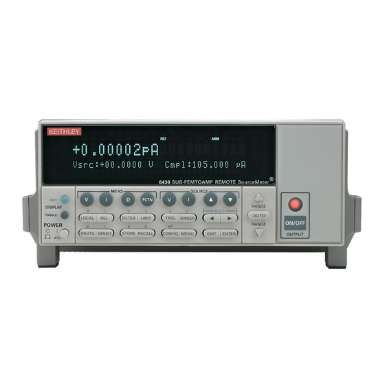
Quick Results Guide Front and rear panels The front and rear panels of the Model 6430 SourceMeter mainframe are shown in Figures 1 and 2. The use of the various instrument controls and connectors will be explained throughout this guide. -
Page 10: Remote Preamp
Quick Results Guide Remote preamp The Model 6430 remote preamp is shown in Figure 3. Figure 4 shows the preamp connector configurations. Figure 3 Remote preamp 250V KEITHLEY Peak Peak GUARD 250V IN/OUT Peak Peak Peak 250V Peak REMOTE Preamp... -
Page 11: Navigating Menus And Entering Numeric Data
Navigating menus and entering numeric data Menu navigation Many operating modes for the Model 6430 are configured using front panel menus. Throughout this guide, menu navigation will be presented as a sequence of key presses and menu item selections. For example, the following sequence selects the auto ohms source mode: Press CONFIG >... -
Page 12: Editing Procedure
Quick Results Guide Editing procedure Press the DISPLAY EDIT key to place the blinking cursor in either the source or com- pliance display field to be edited. If desired, use the RANGE and keys to select the desired source or compliance range. -
Page 13: Source-Measure Terminals
Remote PreAmp MAINFRAME connector to the mainframe REMOTE PreAmp connector. Source-measure terminals The Model 6430 can be used with or without the Remote PreAmp. Table 1 lists each mainframe and equivalent PreAmp terminal. Figure 5 shows the basic input-output configuration. -
Page 14: Dut Connections
Black boot Guard (inner shield) LO (outer shell) Green boot B) Terminal identification for 6430-322-1A cable C) Mainframe Input/Output Configuration DUT connections 2-wire sense connections are shown in Figure 6, and 4-wire sense connections are shown in Figure 7. Use 4-wire remote sensing for the following source-measure conditions: •... - Page 15 Quick Results Guide Figure 6 2-wire *Keithley part number: CA-176-1D. Noise Shield KEITHLEY Triax Cable Preamp Cable* 6430 Test REMOTE Fixture PreAmp Connect to earth safety ground using #18 AWG Connect to REMOTE wire or larger PreAmp connector on rear...
-
Page 16: Cable Guard
To prevent injury from electric shock, the guard shield must be enclosed in a safety shield (i.e., test fixture) that is connected to safety earth ground (as shown in Figure 8). Figure 8 Cable guard *Keithley part number: CA-176-1D. Test Fixture KEITHLEY Triax Cable Guard... - Page 17 Remote PreAmp and mainframe. ³1k½ Banana Plug Cable 6430 Mainframe (rear panel connectors) WARNING: WARNING: NO INTERNAL OPERATOR SERVICABLE PARTS,SERVICE BY QUALIFIED PERSONNEL ONLY. NO INTERNAL OPERATOR SERVICABLE PARTS,SERVICE BY QUALIFIED PERSONNEL ONLY.
-
Page 18: Basic Sourcemeter Operations
Quick Results Guide Basic SourceMeter operations Fundamental SourceMeter operations include source-measure, measure only (V or I), and measure ohms. Source-measure There are four source-measure combinations for the SourceMeter: Source V, Measure I Source I, Measure V Source V, Measure V Source I, Measure I The basic procedure to source-measure is provided in Table 3. -
Page 19: Measure Only (V Or I) Procedure
The SourceMeter can be used to charge/discharge (source/sink) batteries. For operation information on battery charging/discharging (and the associated precautions), see Section 3, Sink operation of the Model 6430 Instruction Manual. Measure only (V or I) The SourceMeter can be used to measure voltage only (voltmeter) or current only (ammeter). -
Page 20: Measure Ohms
Quick Results Guide Measure ohms Measurement methods There are two methods to measure resistance: auto ohms and manual ohms. In auto ohms, the SourceMeter operates as a conventional constant-current source ohmmeter. Select an ohms measurement range (or auto range) and take the reading from the display. In manual ohms, the SourceMeter uses the V/I measurement method. -
Page 21: Auto Ohms Measurement Procedure
Quick Results Guide Table 5 Auto ohms measurement procedure Procedure Details Press MEAS . 1. Select ohms measurement function. Press CONFIG > press MEAS > select 2. Select auto ohms measurement method. SOURCE > select AUTO. Use RANGE and keys to manually select 3. -
Page 22: Offset-Compensated Ohms
NAN (not a number) value of +9.91e37 is used for a function that is not enabled. The fourth data element is the timestamp and the fifth is the status word. See Section 17, FORMat subsystem, of the Model 6430 Instruction Manual for details on all aspects of the data format. -
Page 23: Scpi Commands: Source-Measure And Measure Only
Quick Results Guide SCPI commands SCPI commands to source-measure and measure only are provided in Table 7, and the commands to measure ohms are provided in Table 8. Table 7 SCPI commands: source-measure and measure only Command Description :SOURce:FUNCtion <name> Select source function: <name>... -
Page 24: Programming Examples
Quick Results Guide Programming examples Source-measure example — Table 9 shows a typical command sequence to source 10V and measure current on the 10mA range. Measure-only example — Table 10 shows a typical command sequence to measure current only. Table 9 Command sequence for source-measure example Command* Comments... -
Page 25: Command Sequence For Auto Ohms Example
Quick Results Guide Auto ohms example — Table 11 shows a typical command sequence to use auto ohms to measure resistance. Manual ohms example — Table 12 shows a typical command sequence to use manual ohms to measure resistance. This example uses auto range for current measurements. If you were to use manual ranging, you should select the lowest possible current range for the measurement. -
Page 26: Settings To Optimize Performance
Quick Results Guide Settings to optimize performance Range To achieve best accuracy, the SourceMeter should be on the lowest possible measurement range. In most situations, auto range can be used to automatically select the best range. Auto range is controlled (enabled/disabled) by the AUTO range key (AUTO annunciator indicates auto range is enabled). -
Page 27: Median Filter
Quick Results Guide Digits The SourceMeter can display readings at 3H-digit, 4H-digit, 5H-digit or 6H-digit resolution. In situations where the last digits of the reading are noisy, you can turn those digits off by decreasing display resolution. To set display resolution, press the DIGITS key until the desired number of digits are displayed. -
Page 28: Filter Configuration
Quick Results Guide Auto filter When auto filter is enabled, it automatically selects filter settings that provide the heaviest filtering on the lowest current ranges. The repeating filter count, median filter rank, and moving filter count are automatically set by range to provide optimum filtering. When auto filter is disabled, you can manually choose the desired count and rank settings. - Page 29 1. The speed setting is global for all functions. Therefore, you can use any of the three commands to set speed. 2. The commands to acquire a rel value are not listed in this table (see Section 7 Relative in the Model 6430 SourceMeter Instruction...
-
Page 30: Features To Enhance Dut Testing
NOTE While in the recall mode, buffer statistics (minimum, maximum, peak-to-peak, aver- age and standard deviation) can be displayed using the TOGGLE key. Details about buffer statistics are provided in Section 8 of the Model 6430 SourceMeter Instruc- tion Manual. - Page 31 Table 14 does not provide a complete listing of buffer commands. Documentation for all buffer commands (including the ones for buffer statistics) can be found in Section 8 of the Model 6430 Instruction Manual. Table 14 SCPI commands: data store...
-
Page 32: Sweep Operation
Quick Results Guide Sweep operation Sweep types The four available sweep types are linear staircase, logarithmic staircase, custom, and source memory. Linear staircase sweep When the sweep shown in Figure 10 is triggered to start, the output will go from the bias level to the source level. -
Page 33: Logarithmic Staircase Sweep (Example)
Quick Results Guide Logarithmic staircase sweep This sweep is similar to the linear staircase sweep. The steps, however, are done on a logarithmic scale. The symmetrical log points for the steps are determined by the specified number of sweep points. Figure 11 shows a 5-point log sweep from 1 to 10V. With the desired source (V or I) selected, use the following menu sequence to set the start and stop levels, and the number of sweep points (2 to 2500): Press CONFIG >... -
Page 34: Custom Pulse Sweep (Example)
Quick Results Guide Custom sweep For a custom sweep, the user specifies the number of point in a sweep and the source level at each point. Figure 12 shows a 6-point, 50% duty cycle pulse sweep. The specified voltage level at points P0, P2, and P4 is 1V, while the voltage level at P1, P3 and P5 is 0V. With the desired source (V or I) selected, use the following menu sequence to specify the number of sweep points and the source level at each point: Press CONFIG >... -
Page 35: Sweep Count
NOTE NPLC caching can be used to speed up source memory sweeps. See “NPLC cach- ing” in Section 3 of the Model 6430 Instruction Manual. Sweep count For front panel operation, a sweep can automatically repeat a specified number of times (finite sweep count) or it can repeat continuously (infinite sweep count). -
Page 36: Source Delay
With auto delay selected, the delay setting will depend on which current range and source function is being used (see Section 3, Source delay in the Model 6430 SourceMeter Instruction Manual). Manually, the source delay can be set from 0000.0000 to 9999.9980 sec. -
Page 37: Performing A Log Staircase Sweep
Quick Results Guide Performing a log staircase sweep Perform the following steps to run a log staircase sweep: Configure the source and measure functions. The source level you set becomes the bias level for the sweep. Configure the log staircase sweep, including start and stop values and number of points, as previously explained. - Page 38 SCPI commands for linear, logarithmic and custom sweeps are listed in Table 16. NOTE Table 16 does not provide a complete listing of sweep commands. Documentation for all sweep commands can be found in Section 9 of the Model 6430 SourceMeter Instruction Manual. Table 16...
-
Page 39: Command Sequences For Sweep Examples
Quick Results Guide Programming examples Programming examples for a linear, logarithmic, custom, and source memory sweep are provided in Table 17. Table 17 Command sequences for sweep examples Command* Comments Linear staircase sweep: See Figure 10 *RST Restore GPIB defaults (source V, measure I). :SOUR:VOLT 0 Set bias level to 0V. - Page 40 Quick Results Guide Table 17 (cont.) Command sequences for sweep examples Command* Comments Source memory sweep: Three point sweep; source V, calculate power, source I. ‘Memory location 001 setup: *RST Restore GPIB defaults :SOUR:VOLT:LEV 15 Set voltage source to 15V. :SOUR:MEM:SAVE 1 Save setup in memory location 001.
-
Page 41: Limit Testing
“More testing techniques” section of this guide. For complete details on all aspects of limit testing, see the Model 6430 Instruction Manual, Section 11. Limit 1 (compliance) This hardware (H/W) test uses the programmed compliance as the test limit. At or above the test limit, the source is in compliance. - Page 42 SCPI commands SCPI commands for basic non-binning limit testing are listed in Table 17. NOTE Table 17 does not provide a complete listing of limit commands. See the Model 6430 Instruction Manual for complete documentation. Table 18 SCPI commands: basic non-binning limit testing...
-
Page 43: Command Sequence For Limit 2 Test Example
Quick Results Guide Programming example The programming example in Table 18 tests 1k resistors. If the tested resistor is within 5% of it’s nominal value, it will pass the test. Otherwise the test will fail. Table 19 Command sequence for Limit 2 test example Command* Comments *RST... - Page 44 Quick Results Guide Offset-compensated Thermal EMFs can corrupt low-resistance measurements. An offset-compensated measurement cancels out unwanted offset by performing the following 2-point measurement process: Offset-Compensated = V / I where: V = V2 - V1 I = I2 - I1 V1 and I1 are V and I measurements with the source set to a specific level.
-
Page 45: Varistor Alpha
Quick Results Guide Varistor alpha Determines ALPHA (), which is the logarithmic ratio of two voltage measurement points on a non-linear V-I curve. log I2 I1 ------------------------------ - log V2 V1 where: V1 is the voltage measurement at the first I-Source point (I1). V2 is the voltage measurement at the second I-Source point (I2). - Page 46 The programming example in Table 20 configures the SourceMeter to operate as a power meter (power = V x I). Programming examples for other math functions are provided in the Model 6430 Instruction Manual (see CALCulate1 subsystem). Table 21 Command sequence for power measurement example...
- Page 47 Quick Results Guide...
- Page 48 Keithley Instruments Corporate Headquarters • 28775 Aurora Road • Cleveland, Ohio 44139 • 440-248-0400 • Fax: 440-248-6168 • 1-800-935-5595 • www.keithley.com A Gr e a te r M e asu r e o f Co n fid en c e...
Need help?
Do you have a question about the 6430 and is the answer not in the manual?
Questions and answers