Table of Contents
Advertisement
Quick Links
Advertisement
Table of Contents

Related Manuals for Keithley 6517B


Summary of Contents for Keithley 6517B
- Page 1 Toll Free 1-800-517-8431 Visit us at www.TestEquipmentDepot.com Model 6517B Electrometer User’s Manual 6517B-900-01 Rev. A / June 2008 G R E A T E R M E A S U R E C O N F I D E N C E...
- Page 2 WARRANTY Keithley Instruments, Inc. warrants this product to be free from defects in material and workmanship for a period of one (1) year from date of shipment. Keithley Instruments, Inc. warrants the following items for 90 days from the date of shipment: probes, cables, software, rechargeable batteries, diskettes, and documentation.
- Page 3 Test Equipment Depot - 800.517.8431 - 99 Washington Street Melrose, MA 02176 TestEquipmentDepot.com...
- Page 4 Keithley Instruments, Inc. is strictly prohibited. TSP, TSP-Link, and TSP-Net are trademarks of Keithley Instruments, Inc. All Keithley Instruments product names are trademarks or registered trademarks of Keithley Instruments, Inc. Other brand names are trademarks or registered trademarks of their respective holders.
- Page 5 Test Equipment Depot - 800.517.8431 - 99 Washington Street Melrose, MA 02176 TestEquipmentDepot.com...
-
Page 6: Safety Precautions
Keithley Instruments products are designed for use with electrical signals that are rated Measurement Category I and Measurement Category II, as described in the International Electrotechnical Commission (IEC) Standard IEC 60664. Most measurement, control, and data I/O signals are Measurement Category I and must not be directly connected to mains voltage or to voltage sources with high transient over-voltages. - Page 7 To maintain protection from electric shock and fire, replacement components in mains circuits - including the power transformer, test leads, and input jacks - must be purchased from Keithley Instruments. Standard fuses with applicable national safety approvals may be used if the rating and type are the same.
-
Page 8: Table Of Contents
Table of Contents Section Topic Page Introduction ..................... 1-1 Overview..................... 1-2 Capabilities and features overview............1-2 Options and accessories ..............1-3 Specifications ..................1-5 Unpacking and inspection................1-5 Inspection for damage................1-5 Handling precautions ................1-5 Shipment contents ................1-5 Documentation .................. -
Page 9: Topic Page
..................5-13 Changing function and range ............. 5-13 One-shot triggering ................5-14 Continuous triggering #1 ..............5-15 Continuous triggering #2 ..............5-15 6517B-900-01 Rev. A / Jun 2008 Test Equipment Depot - 800.517.8431 - 99 Washington Street Melrose, MA 02176 TestEquipmentDepot.com... - Page 10 Storing readings in the buffer.............. 5-17 Taking readings with the scanner card ..........5-18 Test sequence: Staircase sweep ............5-19 Index ..........................I-1 6517B-900-01 Rev. A / Jun 2008 Test Equipment Depot - 800.517.8431 - 99 Washington Street Melrose, MA 02176 TestEquipmentDepot.com...
- Page 11 Table of Contents Model 6517B Electrometer User’s Manual This page left blank intentionally. 6517B-900-01 Rev. A / Jun 2008 Test Equipment Depot - 800.517.8431 - 99 Washington Street Melrose, MA 02176 TestEquipmentDepot.com...
-
Page 12: List Of Figures
List of Figures Section Figure Title Page Figure 2-1 Model 6517B front panel..............2-2 Figure 2-2 Model 6517B rear panel ..............2-4 Figure 3-1 Voltage measurements ..............3-3 Figure 3-2 Current measurements ..............3-4 Figure 3-3 Resistance measurements ............3-6 Figure 3-4 Resistivity measurements.............. - Page 13 List of Figures Model 6517B Electrometer User’s Manual This page left blank intentionally. 6517B-900-01 Rev. A / Jun 2008 Test Equipment Depot - 800.517.8431 - 99 Washington Street Melrose, MA 02176 TestEquipmentDepot.com...
-
Page 14: List Of Tables
List of Tables Section Table Title Page Table 4-1 Multiple displays by function ............4-3 Table 4-2 Main menu summary ..............4-5 Table 4-3 Configuration settings for each measurement function ....4-6 Table 4-4 Configuration settings for instrument operations ......4-6 Table 4-5 Menu summary ................ - Page 15 List of Tables Model 6517B Electrometer User’s Manual This page left blank intentionally. viii 6517B-900-01 Rev. A / Jun 2008 Test Equipment Depot - 800.517.8431 - 99 Washington Street Melrose, MA 02176 TestEquipmentDepot.com...
-
Page 16: Introduction
Section 1 Introduction In this section: Topic Page Overview ....................Capabilities and features overview ..........Options and accessories..............Specifications .................. Unpacking and inspection ............... Inspection for damage ..............Handling precautions ..............Shipment contents ................Repacking for shipment ..............Test Equipment Depot - 800.517.8431 - 99 Washington Street Melrose, MA 02176 TestEquipmentDepot.com... -
Page 17: Overview
This section contains general information about the Keithley Instruments Model 6517B Electrometer. If you have any questions after reviewing this information, please contact your local Keithley Instruments representative or call one of our applications engineers at 1-888-KEITHLEY (1-888-534-8453) within the U.S. and Canada. You can also contact us through our website at www.keithley.com. -
Page 18: Options And Accessories
Model 7078-TRX-BNC Adapter: This is a 3-slot male triax to female BNC adapter. This adapter lets you connect a BNC cable to the triax input of the Model 6517B. Suitable for use with the Model 6517B in high voltage applications. - Page 19 BNC connectors and plugs into the option slot of the Model 6517B. Model 6522 Low Current/Low Voltage Scanner Card: This 10-channel low current/low voltage scanner card is terminated with triax connectors and plugs into the option slot of the Model 6517B. Test fixture Model 8009 Resistivity Test Fixture: This is a guarded test fixture for measuring volume and surface resistivities.
-
Page 20: Specifications
• Always grasp the Model 6517B by the covers. • After removing the Model 6517B from its anti-static bag, inspect it for any obvious signs of physical damage; report any such damage to the shipping agent immediately. • When the Model 6517B is not installed and connected, keep the unit in its anti-static bag and store it in the original packing carton. -
Page 21: Repacking For Shipment
Section 1: Introduction Model 6517B Electrometer User’s Manual Repacking for shipment Should it become necessary to return the Model 6517B for repair, carefully pack the unit in its original packing carton or the equivalent, and follow these instructions: • Call the repair department toll-free at 1-888-KEITHLEY (1-888-534-8453), within the U.S. -
Page 22: Getting Started
Section 2 Getting Started In this section: Topic Page Introduction ..................... Front and rear panel familiarization............Front panel summary ..............Rear panel summary ..............Power-up ....................Line power connection ..............Power-up procedure ............... Display ....................Primary display line ................ Secondary display line .............. -
Page 23: Introduction
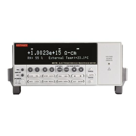
Model 6517B Electrometer User’s Manual Introduction This section contains identification and descriptions of controls and components of the Keithley Instruments Model 6517B Electrometer and detailed information for powering up the Model 6517B. Front and rear panel familiarization Front panel summary... - Page 24 Indicator light is on when in operation, off in standby. OPTION CARD KEY Use to program and operate an optional feature. Also use to view external scanner channels. 6517B-900-01 Rev. A / Jun 2008 Return to Section Topics Test Equipment Depot - 800.517.8431 - 99 Washington Street Melrose, MA 02176...
-
Page 25: Rear Panel Summary
Follows the signal amplitude applied to the INPUT terminal. With GUARD on, PREAMP OUT is connected to the inner shell of the INPUT triax connector to configure the input for guarded voltage measurements. Referenced to COMMON. See the Model 6517B Reference Manual for more information. Return to Section Topics 6517B-900-01 Rev. - Page 26 Connects the safety interlock to a test fixture using an appropriate cable. Interlock is automatically enabled when the appropriate interlock cable is connected to the 6517B. Rated at 50-60 Hz, 140 VA max. The interlock’s CS-1305 connector includes four pins (left to right as viewed from rear of the 6517B): •...
-
Page 27: Power-Up
Model 6517B Electrometer User’s Manual Power-up Line power connection Follow the procedure below to connect the Model 6517B to line power and turn on the instrument. CAUTION Operating the instrument on an incorrect line voltage may cause damage to the instrument, possibly voiding the warranty. -
Page 28: Secondary Display Line
( and ) to display the additional information. Bench defaults The Model 6517B can save ten user setups in non-volatile memory. You can select one of the user setups as the power-on default or have the instrument power up to either of the two factory defaults (optimized for “BENCH”... - Page 29 Section 2: Getting Started Model 6517B Electrometer User’s Manual This page left blank intentionally. Return to Section Topics 6517B-900-01 Rev. A / Jun 2008 Test Equipment Depot - 800.517.8431 - 99 Washington Street Melrose, MA 02176 TestEquipmentDepot.com...
-
Page 30: Figure 3-3 Resistance Measurements
Section 3 Basic Measurements In this section: Topic Page Introduction ..................... Changing functions ................. Voltage measurements................Guarding ..................Current measurements................Resistance measurements..............Auto V-Source ................. Amps Rel..................Resistivity measurements ............... Charge measurements................Auto discharge ................3-10 Temperature and humidity measurements .......... -
Page 31: Basic Measurements
Introduction This section provides information on taking basic measurements. For more detailed information, Section 4 and the Keithley Instruments Model 6517B Reference Manual. Changing functions To avoid erratic operation, always enable zero check (“ZeroCheck” displayed) before selecting one of the other measurement functions (V, I, R, or Q). The Z-CHK key controls zero check (see... -
Page 32: Guarding
Place the cursor on the desired selection (OFF to disable or ON to enable) and press ENTER. Use the EXIT key to back out of the menu. 6517B-900-01 Rev. A / Jun 2008 Return to Section Topics Test Equipment Depot - 800.517.8431 - 99 Washington Street Melrose, MA 02176... -
Page 33: Current Measurements
With zero check enabled (“ZeroCheck” displayed), select the amps function by pressing I. The Z-CHK key is used to enable or disable zero check. To achieve optimum accuracy for low current measurements, zero correct the Model 6517B. To do this, use the RANGE key to select the lowest measurement range (20pA) and press REL. -
Page 34: Resistance Measurements
For manual ranging, use the RANGE keys to select a measurement range consistent with the expected resistance. Connect the Model 6517B to the test fixture. Generic connections are shown in Figure 3-3. Note that this connection scheme requires that ammeter LO be internally connected to... -
Page 35: Auto V-Source
Hazardous voltages may be present on the output and guard terminals. To prevent electrical shock that could cause injury or death, NEVER make or break connections to the Model 6517B while the output is on. Power off the equipment from the front panel or disconnect the main power cord from the rear of the Model 6517B before handling cables connected to the outputs. -
Page 36: Resistivity Measurements
For manual ranging, use the RANGE keys ( ) to select a measurement range consistent with the expected resistance. Connect the Model 6517B to the Model 8009 test fixture as shown in Figure 3-4, and set the switch on the test fixture to the desired measurement type (Surface or Volume). - Page 37 WARNING prevent electrical shock that could cause injury or death, NEVER make or break connections to the Model 6517B while the output is on. Power off the equipment from the front panel or disconnect the main power cord from the rear of the Model 6517B before handling cables connected to the outputs.
-
Page 38: Charge Measurements
Connect the test cable (see Figure 3-5) to the input of the Model 6517B. With the input open, disable zero check. If needed, press REL to zero the display. Connect the instrument to the charge to be measured as shown in Figure 3-5. -
Page 39: Auto Discharge
Charge measurements Temperature and humidity measurements The Model 6517B can make external temperature measurements from –25°C to 150°C using the Keithley Instruments Model 6517-TP type K thermocouple (which is a supplied accessory). The Model 6517B can make relative humidity measurements (0 to 100%) using the Keithley Instruments Model 6517-RH humidity probe (which is available as an option). -
Page 40: Measurement Control
Use the EXIT key to back out of the menu. Temperature units All temperature readings by the Model 6517B can be displayed in Celsius (°C), Fahrenheit (°F), or Kelvin (K). BENCH reset selects Celsius (°C) measurement units. Perform the following steps to change units: Press MENU to display the main menu. -
Page 41: Display Reading Options
External temperature and humidity are selected as data store elements from the data store configuration menu (see Buffer (data store) for more information). 3-12 Return to Section Topics 6517B-900-01 Rev. A / Jun 2008 Test Equipment Depot - 800.517.8431 - 99 Washington Street Melrose, MA 02176 TestEquipmentDepot.com... -
Page 42: Measurement Options
Section 4 Measurement Options In this section: Topic Page Introduction ..................... Multiple displays ..................Menus ..................... Navigating menus ................Voltage source..................Connections ..................Basic operation ................Configuring V-Source..............Relative ....................Configuring rel................. 4-10 Zero check ....................4-10 Zero correct ..................... 4-10 Triggering .................... - Page 43 External scanning ................... 4-22 Trigger connections ................ 4-23 Configure external channels ............4-23 Perform the scan ................4-23 Return to Section Topics 6517B-900-01 Rev. A / Jun 2008 Test Equipment Depot - 800.517.8431 - 99 Washington Street Melrose, MA 02176 TestEquipmentDepot.com...
-
Page 44: Introduction
This section describes the details of taking measurements. Configuration options, triggers, reading storage, and scanning are just a few of the topics discussed. You will find this information useful whether operating the Model 6517B from the front panel or IEEE-488 bus. Multiple displays Each measurement function and some operations provide multiple displays by using the bottom line of the front panel. - Page 45 Return to Section Topics 6517B-900-01 Rev. A / Jun 2008 Test Equipment Depot - 800.517.8431 - 99 Washington Street Melrose, MA 02176 TestEquipmentDepot.com...
-
Page 46: Menus
Print buffer data Menus There are two basic menu structures used by the Model 6517B: The main menu and the CONFIG menus. The main menu accesses items for which there are no dedicated keys. The CONFIG menus are used to configure measurement functions and other instrument operations. -
Page 47: Navigating Menus
When is displayed, use the cursor key. The cursor keys have an auto-repeat feature. Return to Section Topics 6517B-900-01 Rev. A / Jun 2008 Test Equipment Depot - 800.517.8431 - 99 Washington Street Melrose, MA 02176 TestEquipmentDepot.com... -
Page 48: Voltage Source
Hazardous voltages may be present on the output and guard terminals. To prevent electrical shock that could cause injury or death, NEVER make or break connections to the Model 6517B while the output is on. Power off the equipment from the front panel or disconnect the main power cord from the rear of the Model 6517B before handling cables connected to the outputs. -
Page 49: Figure 4-3 Fvmi Connections
Section 4: Measurement Options Model 6517B Electrometer User’s Manual Figure 4-2 Independent V-Source connections Figure 4-3 FVMI connections Return to Section Topics 6517B-900-01 Rev. A / Jun 2008 Test Equipment Depot - 800.517.8431 - 99 Washington Street Melrose, MA 02176 TestEquipmentDepot.com... -
Page 50: Basic Operation
A rel value can be established for each measurement function. The state and value of rel for each measurement function are saved when changing functions. Once a rel value is established for a measurement function, the value is the same for all ranges. 6517B-900-01 Rev. A / Jun 2008 Return to Section Topics Test Equipment Depot - 800.517.8431 - 99 Washington Street Melrose, MA 02176... -
Page 51: Configuring Rel
Model 6517B Reference Manual. Triggering is configured from the Trigger Configuration menu which is accessed by pressing CONFIG and then TRIG. There are two trigger modes for the Model 6517B; basic and advanced. These two trigger modes are summarized by the simplified trigger models shown in... -
Page 52: Idle
The instrument is in idle whenever it is not within one of the layers of the trigger model. When the Model 6517B is taken out of idle by pressing TRIG (or sending :INIT or :INIT:CONT ON over the bus), the ARM indicator turns on and operation proceeds in the trigger model. -
Page 53: Control Sources
After each measurement (device action), an output trigger pulse occurs and is available at the rear panel of the Model 6517B. When used with an external scanner, each output trigger is used to select the next channel in a scan (see External scanning for more information). -
Page 54: Speed
Set resolution by placing the cursor on the menu option and pressing ENTER. Filter Filtering stabilizes noisy measurements. The Model 6517B uses a digital filter and a median filter. When a filter is enabled by pressing FILTER (FILT annunciator turns on), the selected filter for that measurement function is in effect. -
Page 55: Filter Types
Model 6517B Electrometer User’s Manual Filter types The Model 6517B has two types of digital filters: averaging and advanced. Both types are a simple average of 1 to 100 reading conversions. The difference is a user-programmed “noise window” for the advanced filter. The noise window (expressed as a percentage of range) allows a faster... -
Page 56: Configuring Filters
ENTER. Buffer (data store) The Model 6517B has a buffer that can store from one to 15,706 readings. The actual number of readings that can be stored in the buffer depends on how many optional data elements are included for each reading (see Section 8 of the Reference Manual). -
Page 57: Math
X is the normal display reading Y is the user-entered reference value PD is the displayed result (percent deviation) 4-16 Return to Section Topics 6517B-900-01 Rev. A / Jun 2008 Test Equipment Depot - 800.517.8431 - 99 Washington Street Melrose, MA 02176 TestEquipmentDepot.com... -
Page 58: Selecting And Configuring Math
Use the menu items to select and configure math. A menu item is selected by placing the cursor on it and pressing ENTER. Parameter values are changed using the cursor keys and the RANGE keys ( , and then pressing ENTER. 6517B-900-01 Rev. A / Jun 2008 Return to Section Topics 4-17 Test Equipment Depot - 800.517.8431 - 99 Washington Street Melrose, MA 02176... -
Page 59: Enabling Math
Display = LOG10 (reading) Math is disabled by pressing MATH a second time. Additional math operations In addition to the math performed on single readings described above, the Model 6517B has these math operations: • Math performed on buffered readings (maximum and minimum values, average, and standard deviation). -
Page 60: Test Sequences
Model 6517B Electrometer User’s Manual Section 4: Measurement Options Test sequences The following information summarizes the built-in test sequences of the Model 6517B. Detailed information on test sequences can be found in the Reference Manual. Configuring test sequences A test sequence is selected and configured from the CONFIGURE SEQUENCE menu as follows: Press CONFIG and then SEQ to display the sequence configuration menu. -
Page 61: Connections
Model 6517B. TRIGLINK: Test will start when a trigger pulse (via TRIG LINK connector) is received by the Model 6517B. You will also be prompted to select the input line for the trigger. Connections Hazardous voltages may be present on the output and guard terminals. To... -
Page 62: Running A Test
Internal scanning The Model 6517B can be used with a scanner card (such as the Keithley Instruments Model 6521 or Model 6522) installed in the option slot of the instrument. This section provides basic information for scanning internal channels. -
Page 63: Close/Open Channels
ENTER. External scanning The Model 6517B can be used with a scanner card installed in an external scanning mainframe (for example, the Keithley Instruments Model 7001 or 7002 Switch System). With the use of external triggering, the Model 6517B can measure and store each scanned channel. -
Page 64: Trigger Connections
The scanner configuration menu is used to specify the number of channels (external inputs) for the scan. If a scanner card is installed in the option slot of the Model 6517B, use procedure A. If the option slot is empty, use procedure B. - Page 65 . Press ENTER to continue. On the Model 6517B, you will be asked if you wish to use the scan timer. The timer is used to provide a time interval between each scan. If you select YES, enter the interval (in seconds).
-
Page 66: Remote Operation
Section 5 Remote Operation In this section: Topic Page Overview ....................Software support ..................LabView driver ................Remote interfaces ................... IEEE-488 bus .................. RS-232 interface ................Common commands ................SCPI commands ..................SCPI command syntax..............SCPI signal-oriented commands............. SCPI subsystem commands ............ -
Page 67: Overview
In this mode, you use DDCs instead of common commands and SCPI commands. This mode allows you to use the Model 6517B as an easy replacement for the Model 617 Electrometer. The 6517B can use existing programs written for the Model 617 without any code modifications. -
Page 68: Rs-232 Interface
IEEE-488 connections Address and language selection The Model 6517B is shipped from the factory with the IEEE-488 bus selected, the primary address set to 27 and the SCPI language mode selected. The primary address is displayed on power up if the IEEE-488 bus is the selected interface. - Page 69 Model 6517B Electrometer User’s Manual RS-232 connections The RS-232 serial port of the Model 6517B can be connected to the serial port of a computer using a standard, straight-through (not null modem) RS-232 cable terminated with DB-9 connectors. The serial port is located on the rear panel of the Model 6517B and is labeled “RS232.”...
-
Page 70: Common Commands
SCPI commands In the Model 6517B, you are given access to control settings that are hidden on other instruments. Because the instrument has more control points available, it requires more commands than its counterparts to perform comparable tasks. -
Page 71: Scpi Command Syntax
However, you do not have to use the mixed capitalization. The Model 6517B accepts commands in any combination of upper and lower case. For example, all of the following are valid forms of the SENSe1:VOLTage[:DC]:REFerence command:... - Page 72 A leading colon instructs the Model 6517B to interpret the command starting at the root (highest level) of the command tree. Since the Model 6517B also starts at the root each time you send it a new command, the leading colon is not needed (although the instrument will accept it if you send it).
-
Page 73: Scpi Signal-Oriented Commands
This query command is used to request the latest post-processed reading. After sending this command and addressing the Model 6517B to talk, the reading will be sent to the computer. This command does not trigger a measurement, it simply requests the last available reading. - Page 74 Select ohms V-Source mode (MANual or AUTO) :VSControl <name> Select ohms type (NORMal or RESistivity) :MSELect <name> 6517B-900-01 Rev. A / Jun 2008 Return to Section Topics Test Equipment Depot - 800.517.8431 - 99 Washington Street Melrose, MA 02176 TestEquipmentDepot.com...
- Page 75 Specify settling time for internal card; 0 to 99999.9999 (sec.) :SMEThod <name> Enable the specified scan: INTernal, EXTernal or NONE :LSELect <name> 5-10 Return to Section Topics 6517B-900-01 Rev. A / Jun 2008 Test Equipment Depot - 800.517.8431 - 99 Washington Street Melrose, MA 02176 TestEquipmentDepot.com...
-
Page 76: Trigger Model
:SVOLtage2 <NRf> Specify measure delay 2; 0 to 99999.9s :MDELay2 <NRf> Surface resistivity test path: :SRESistivity 6517B-900-01 Rev. A / Jun 2008 Return to Section Topics 5-11 Test Equipment Depot - 800.517.8431 - 99 Washington Street Melrose, MA 02176 TestEquipmentDepot.com... - Page 77 :STIMe <NRf> Status register The status register structure of the Model 6517B lets you monitor and act upon numerous events that occur. Many programming decisions can be made by monitoring the measurement event register and the operation event register. See Section 14 of the User’s Manual for details of the status registers.
-
Page 78: Program Examples
Program examples All examples presume QuickBASIC version 4.5 or higher and a Keithley Instruments KPC-488.2 or CEC IEEE-488 interface card with CEC driver version 2.11 or higher, with the Model 6517B at address 27 on the IEEE-488 bus. Changing function and range The Model 6517B has independent controls for each of its measurement functions. -
Page 79: One-Shot Triggering
Changing any of the settings in the TRIGger subsystem does not automatically arm the Model 6517B for triggers. The following program sets up the Model 6517B to take one reading each time it receives an external trigger pulse. 'Example program that demonstrates one-shot external triggering 'For QuickBASIC 4.5 and KPC-488.2/CEC interface card. -
Page 80: Continuous Triggering #1
Continuous triggering #1 The following example program sets up the Model 6517B to take readings as fast as it can once it receives an external trigger. The actual reading rate will depend upon other factors, such as A/D integration time, autorange on/off, and so on. -
Page 81: Generating Srq On Buffer Full
CALL SPOLL(27, poll%, status%) IF (poll% AND 64)=0 THEN GOTO WaitSRQ Notice that after the program has detected an asserted SRQ line, it serial polls the Model 6517B to determine if it is the device requesting service. This is necessary for two reasons: •... -
Page 82: Storing Readings In The Buffer
TRACe:FEED:CONTrol PRETrigger The following example program sets up the Model 6517B to take 20 readings as fast as it can into the buffer, then reads the data back after the buffer has filled. The readings will be stored with the timestamp and other information, but the program reads back only the reading values and timestamp. - Page 83 The following example program sets up the Model 6517B using a scan list to measure DC voltage on channels 1, 2, and 3. The meter takes ten sets of readings, with each set spaced 15 seconds apart, and each of the three readings in each group taken as fast as possible. The Model 6517B 5-18...
-
Page 84: Test Sequence: Staircase Sweep
' now the buffer is armed CALL SEND(27, "rout:scan (@1:3)", status%) CALL SEND(27, "rout:lsel init", status%) 'Start everything CALL SEND(27, "init", status%) 'Initialize reading$ while the 6517B is busy taking readings reading$ = SPACE$(2500) WaitSRQ: IF (NOT(srq%()) THEN GOTO WaitSRQ CALL SPOLL(27, poll%, status%) IF (poll% AND 64)=0 THEN GOTO WaitSRQ CALL SEND(27, "form:elem read,time,chan", status%) - Page 85 FOR I = 1 TO 11 r$ = MID$(DATA!$, A, 13) PRINT r$ A = A + 14 NEXT I 5-20 Return to Section Topics 6517B-900-01 Rev. A / Jun 2008 Test Equipment Depot - 800.517.8431 - 99 Washington Street Melrose, MA 02176 TestEquipmentDepot.com...
-
Page 86: Index
......5-15 Inspection ..........1-5 Control sources ........4-12 Instruction manual ........1-5 Counters ..........4-12 Internal scanning ........4-21 Current measurements ......3-4 Keys 6517B-900-01 Rev. A / Jun 2008 Test Equipment Depot - 800.517.8431 - 99 Washington Street Melrose, MA 02176 TestEquipmentDepot.com... - Page 87 .......3-4 Resistivity measurements ......3-7 Resolution ..........4-13 RS-232 interface ........5-3 Configuration ........5-4 Connections ........5-4 Selection ...........5-4 Standard ...........5-3 Running a test ........4-21 6517B-900-01 Rev. A / Jun 2008 Test Equipment Depot - 800.517.8431 - 99 Washington Street Melrose, MA 02176 TestEquipmentDepot.com...
- Page 88 Service Form Model No. Serial No. Date Name and Telephone No. Company List all control settings, describe problem and check boxes that apply to problem. Intermittent Analog output follows display Particular range or function bad; specify IEEE failure Obvious problem on power-up Batteries and fuses are OK Front panel operational All ranges or functions are bad...
- Page 89 Test Equipment Depot - 800.517.8431 - 99 Washington Street Melrose, MA 02176 TestEquipmentDepot.com...
- Page 90 12/06 Test Equipment Depot - 800.517.8431 - 99 Washington Street Melrose, MA 02176 TestEquipmentDepot.com...
Need help?
Do you have a question about the 6517B and is the answer not in the manual?
Questions and answers