Table of Contents
Advertisement
Quick Links
Advertisement
Table of Contents

Subscribe to Our Youtube Channel
Related Manuals for Keithley 6485


Summary of Contents for Keithley 6485
- Page 1 Model 6485 Picoammeter Model 6487 Picoammeter/Voltage Source User’s Manual 6487-900-01 Rev. B / January 2003 Test Equipment Depot - 800.517.8431 - 99 Washington Street Melrose, MA 02176 - TestEquipmentDepot.com G R E A T E R M E A S U R E...
- Page 2 WARRANTY Keithley Instruments, Inc. warrants this product to be free from defects in material and workmanship for a period of 1 year from date of shipment. Keithley Instruments, Inc. warrants the following items for 90 days from the date of shipment: probes, cables, rechargeable batteries, diskettes, and documentation.
- Page 3 Model 6485 Picoammeter Model 6487 Picoammeter/ Voltage Source User’s Manual ©2003, Keithley Instruments, Inc. All rights reserved. Cleveland, Ohio, U.S.A. First Printing, January 2003 Document Number: 6487-900-01 Rev. B...
- Page 4 Each new Revision includes a revised copy of this print history page. Revision A (Document Number 6487-900-01)...............October 2002 Revision B (Document Number 6487-900-01) ............... January 2003 All Keithley product names are trademarks or registered trademarks of Keithley Instruments, Inc. Other brand names are trademarks or registered trademarks of their respective holders.
- Page 5 Keithley products are designed for use with electrical signals that are rated Measurement Category I and Measurement Category II, as described in the International Electrotechnical Commission (IEC) Standard IEC 60664. Most measurement, control, and data I/O signals are Measurement Category I and must not be directly connected to mains voltage or to voltage sources with high transient over-voltages.
- Page 6 To maintain protection from electric shock and fire, replacement components in mains circuits, including the power transformer, test leads, and input jacks, must be purchased from Keithley Instruments. Standard fuses, with applicable national safety ap- provals, may be used if the rating and type are the same. Other components that are not safety related may be purchased from other suppliers as long as they are equivalent to the original component.
-
Page 7: Table Of Contents
Safety symbols and terms ..............Unpacking and inspection ..............Options and accessories ..............Additional references ................Features ..................... Model 6485 front and rear panel familiarization ......... Model 6485 front panel summary ............Model 6485 rear panel summary ............1-11 Analog output .................. - Page 8 Connection fundamentals ................Model 6485 connections ..............Model 6487 connections ..............Basic connections to DUT ................Model 6485 DUT connections ............. Model 6487 DUT connections ............. Input voltage overload (OVRVOLT message) ..........Using a test fixture ..................General purpose test fixture ..............
- Page 9 Model 6487 voltage source operation ............3-12 Configuring the voltage source ............3-12 Sourcing voltage ................3-13 Compliance indication ................ 3-13 Open interlock indication ..............3-14 SCPI commands — voltage source ........... 3-14 Programming example — voltage ............. 3-14 Range, Units, Digits, Rate, and Filters Range, units, and digits ................
- Page 10 Remote Operation and Commands Selecting and configuring an interface ............Interfaces ..................... Connections ..................Front panel GPIB operation ..............Remote commands ..................General bus commands ..............Common commands ................Signal oriented commands..............SCPI command subsystems ............... Programming syntax ................Specifications General Measurement Considerations Measurement considerations ..............
- Page 11 Figure 2-8 Basic Model 6487 ohms connections............Figure 2-9 Shielding for Model 6487 measurements (unguarded) ......Figure 2-10 General purpose test fixture connections to Model 6485 ...... 2-10 Figure 2-11 General purpose test fixture connections to Model 6487 ...... 2-11...
- Page 12 Table 2-1 Summary of measurement considerations..........2-16 Measurements and Sourcing Voltage Table 3-1 Basic Model 6485 and 6487 current measurement capabilities....Table 3-2 Basic Model 6487 voltage source output capabilities......Table 3-3 SCPI commands — zero check and zero correct ........
-
Page 13: Getting Started
Features • Model 6485 front and rear panel familiarization — Summarizes the controls and connectors of the Model 6485 as well as providing information on the front panel display. • Model 6487 front and rear panel familiarization — Summarizes the controls and connectors of the Model 6487 and provides information on the front panel display. -
Page 14: Introduction
General information Warranty information Warranty information is located at the front of this manual. Should your Model 6485 or 6487 require warranty service, contact the Keithley representative or authorized repair facility in your area for further information. When returning the instrument for repair, be sure to fill out and include the service form at the back of this manual to provide the repair facility with the necessary information. -
Page 15: Contact Information
Contact information Worldwide phone numbers are listed at the front of this manual. If you have any ques- tions, please contact your local Keithley representative or call one of our Application Engineers at 1-800-348-3735 (U.S. and Canada only). Safety symbols and terms... -
Page 16: Options And Accessories
Getting Started Model 6485 and 6487 User’s Manual Package content Model 6485 The following items are included with every Model 6485 order: • Model 6485 Picoammeter with line cord. • Low Noise Cable with Male BNC on both ends (Model 4801). - Page 17 Model 6485 and 6487 User’s Manual Getting Started Model 4803 Low Noise Cable Kit — This cable kit includes: – 15m (50 ft) of low noise coax cable – 10 male BNC connectors – 5 female BNC chassis-mount connectors Model 7078-TRX-BNC adapter — 3-slot male triax to female BNC.
- Page 18 (EMI). Model 7009-5 is 5 ft. long. Models 8501-1 and 8501-2 trigger link cables — Connects the Model 6485/6487 to other instruments with Trigger Link connectors (e.g., Model 7001 Switch System). Model 8501- 1 is lm long;...
-
Page 19: Additional References
Model 6485 and 6487 User’s Manual Getting Started Rack mount kits Model 4288-1 single fixed rack mount kit — Mounts a single Model 6485/6487 in a standard 19-inch rack. Model 4288-2 side-by-side rack mount kit — Mounts two instruments (Models 182, 428, 486, 487, 2000, 2001, 2002, 2010, 2400, 2410, 2420, 2430, 6430, 6485, 6487, 6517A, 7001) side-by-side in a standard 19-inch rack. -
Page 20: Features
Limits — Set up to two stages of high and low reading limits to test devices (see Section 8 of the Model 6485 Instruction Manual or Model 6487 Reference Manual). Digital I/O port (Model 6487 only) — Four output lines and one input line to con- •... -
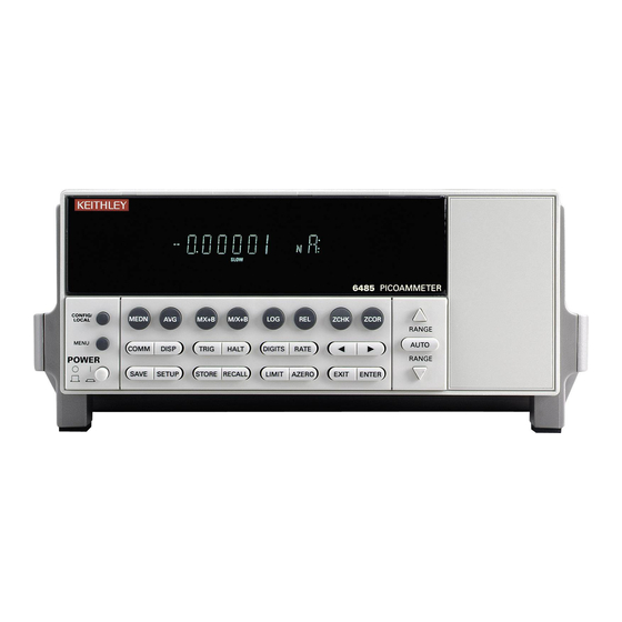
Page 21: Figure 1-1 Model 6485 Front Panel
When in Remote operation (REM annunciator lit), cancels GPIB remote mode. MENU Provides access to menu. POWER Power switch. In position turns 6485 on (I), out position turns it off (O). 2 Function keys MEDN Use to control and modify properties of the median filter. - Page 22 1-10 Getting Started Model 6485 and 6487 User’s Manual HALT Stops measurement process. Puts 6485 in idle state. DIGITS Use to set display resolution. RATE Use to select measurement rate. Use to control cursor position for making selections or editing values.
-
Page 23: Model 6485 Rear Panel Summary
Model 6485 and 6487 User’s Manual Getting Started 1-11 Model 6485 rear panel summary The rear panel of the Model 6485 is shown in Figure 1-2. Figure 1-2 Model 6485 rear panel CAT I MADE IN U.S.A. IEEE-488 ANALOG OUT... -
Page 24: Analog Output
115V and 230VAC (nominal) at line frequencies of 50 or 60Hz automatically and over the bus. Changing line voltages requires changing fuses. Analog output The Model 6485 has an analog output on the rear panel. The ANALOG OUT provides a scaled, inverting ±2V output. A full-scale reading corresponds to ±2V output. See “Ana- log output,”... -
Page 25: Model 6487 Front And Rear Panel Familiarization
Model 6485 and 6487 User’s Manual Getting Started 1-13 Model 6487 front and rear panel familiarization Model 6487 front panel summary The front panel of the Model 6487 is shown in Figure 1-3. Figure 1-3 Model 6487 front panel 6487 PICOAMMETER /VOLTAGE SOURCE... - Page 26 1-14 Getting Started Model 6485 and 6487 User’s Manual OPER Toggles the Vsource state (the Vsource state is displayed by an indicator). (Configured using the CONFIG >> OPER key sequence.) V-SOURCE ¹ Increments voltage source value V-SOURCE ƒ Decrements voltage source value...
- Page 27 Model 6485 and 6487 User’s Manual Getting Started 1-15 7 Display annunciators * (asterisk) Readings being stored in buffer. (more) Indicates additional selections are available. AUTO Autorange enabled. BUFFER Recalling readings stored in buffer. Questionable reading or invalid cal step.
-
Page 28: Model 6487 Rear Panel Summary
1-16 Getting Started Model 6485 and 6487 User’s Manual Model 6487 rear panel summary The rear panel of the Model 6487 is shown in Figure 1-4. Figure 1-4 Model 6487 rear panel MADE IN U.S.A. CAT I IEEE-488 ANALOG OUT... -
Page 29: Voltage Source
Model 6485 and 6487 User’s Manual Getting Started 1-17 5 TRIGGER LINK Eight-pin micro-DIN connector for sending and receiving trigger pulses among connected instru- ments. Use a trigger link cable or adapter, such as Models 8501-1, 8501-2, 8502, and 8503. -
Page 30: Analog Output
1-18 Getting Started Model 6485 and 6487 User’s Manual Analog output The Model 6487 has an analog output on the rear panel. The ANALOG OUT provides a scaled, inverting ±2V output. A full-scale reading corresponds to ±2V output. See “Ana- log output,”... -
Page 31: Power-Up
1-19 Power-up Line power connection Follow the procedure below to connect the Model 6485/6487 to line power and turn on the instrument. Check to see that the line voltage indicated in the window of the fuse holder assem- (Figure 1-2 Figure 1-4) is correct for the operating voltage in your area. -
Page 32: Power-Up Sequence
Power-up sequence The following power-up sequence occurs when the Model 6485/6487 is turned on: The Model 6485/6487 performs self-tests on its EPROM and RAM with all digits and annunciators turned on. (For the Model 6487 at power-up, the VOLTAGE SOURCE OPERATE LED will come on for 0.7 seconds to indicate that it is func- tional.) If a failure is detected, the instrument momentarily displays an error mes-... -
Page 33: Default Settings
1-21 Default settings The Model 6485/6487 can be restored to one of five setup configurations: factory default (FACT), three user-saved (USR0, USR1, and USR2), and bus default (GPIB). As shipped from the factory, Model 6485/6487 powers up to the factory default settings. Factory default settings provide a general purpose setup for front panel operation, while the bus default (GPIB) settings do the same for remote operation. -
Page 34: Table 1-1 Model 6485 Default Settings
1-22 Getting Started Model 6485 and 6487 User’s Manual Table 1-1 Model 6485 default settings Factory GPIB Setting (:SYStem:PRESet) (*RST) Trig Layer (CONF-TRIG): TRIG: TRIG-IN Arm-In Source Event Arm Layer (CONF-ARM): Arm-In Source Event Arm Count Input Trigger Link Line... - Page 35 Model 6485 and 6487 User’s Manual Getting Started 1-23 Table 1-1 (cont.) Model 6485 default settings Factory GPIB Setting (:SYStem:PRESet) (*RST) Rate: Slow NPLC 6.0 (60Hz) or 5.0 (50Hz) Rel: Rel Value (VAL) RS-232: No effect (Off at factory) All Settings...
-
Page 36: Table 1-2 Model 6487 Default Settings
1-24 Getting Started Model 6485 and 6487 User’s Manual Table 1-2 Model 6487 default settings Factory GPIB Setting (:SYStem:PRESet) (*RST) Arm Layer (CONFIG ARM): Arm-In Source Event Arm Count Input Trigger Link Line Source Bypass NEVER Output Trigger Link Line... - Page 37 Model 6485 and 6487 User’s Manual Getting Started 1-25 Table 1-2 (cont.) Model 6487 default settings Factory GPIB Setting (:SYStem:PRESet) (*RST) RS-232: No effect (Off at factory) All Settings No effect Trigger Layer (CONFIG TRIG): Trig-In Source Event Trigger Count...
-
Page 38: Menu
1-26 Getting Started Model 6485 and 6487 User’s Manual Menu Many aspects of operation are configured through the menus summarized in Table 1-3 Table 1-4. Refer to the section listed in the table for in-depth information. To access the menu, press the MENU key. Use the RANGE keys to scroll through the menu items ¹... -
Page 39: Scpi Programming
(?) that follows the command word. A query command requests (queries) the pro- grammed status of that command. When a query command is sent and Model 6485/6487 is addressed to talk, the response message is sent to the computer. - Page 40 1-28 Getting Started Model 6485 and 6487 User’s Manual...
-
Page 41: Connections
Connections • Connection fundamentals — Covers fundamental information about connecting test circuits to the picoammeter. • Basic connections to DUT — Details connecting test circuits to the picoammeter for current measurement and Model 6487 ohms measurements. • Using a test fixture —... -
Page 42: Connection Fundamentals
CAT I INPUT Shield (LO or GND) Maximum input levels The maximum input levels to the Model 6485 are summarized in Figure 2-2. WARNING The maximum safe voltage between picoammeter LO and chassis ground (common mode voltage) is 42V. The Model 6485 does not internally limit the LO-to-chassis voltage. -
Page 43: Model 6487 Connections
Model 6485 and 6487 User’s Manual Connections Figure 2-2 Model 6485 maximum input levels Input HI Max Continuous Input Signal * Input LO 42V Peak Chassis Ground * Maximum Continuous Input Signals 220V Peak, DC to 60Hz sine wave Low noise input cables When making precision measurements, you should always use low noise cables. -
Page 44: Figure 2-4 Model 6487 Maximum Input Levels
Connections Model 6485 and 6487 User’s Manual Voltage source output connectors The rear panel V-SOURCE OUTPUT HI and LO connectors (see Figure 1-4 Section are used to connect the voltage source to the DUT. The voltage source is primarily used for ohms measurements. -
Page 45: Basic Connections To Dut
Current limiting resistors are required for DUTs capable of forcing voltages 220V or greater. Damage to the instrument may result if volt- ages greater than 220V are forced on the Model 6485 Input HI. Noise and safety shields Figure 2-6 shows typical measurement shielding. -
Page 46: Model 6487 Dut Connections
Model 6485 and 6487 User’s Manual WARNING The maximum safe voltage between picoammeter LO and chassis ground (common mode voltage) is 42V. The Model 6485 does not internally limit the LO-to-chassis voltage. Exceeding 42V can create a shock hazard. If it is possible for the DUT or external supply to present more than... -
Page 47: Figure 2-7 Basic Model 6487 Current Measurement Connections
Model 6485 and 6487 User’s Manual Connections Figure 2-7 Basic Model 6487 current measurement connections 6487 INPUT* * Maximum Continuous Input: 505V Peak WARNING If it is possible for the DUT or external supply to present more than 505V to the input HI, it is imperative that the connection between... -
Page 48: Figure 2-8 Basic Model 6487 Ohms Connections
Connections Model 6485 and 6487 User’s Manual Figure 2-8 Basic Model 6487 ohms connections 6487 INPUT* V-SOURCE OUTPUT * Maximum Continuous Input: 505V Peak Noise and safety shields Figure 2-9 shows typical measurement shielding. In (A), a noise shield is used to prevent unwanted signals from being induced on the picoammeter input. -
Page 49: Input Voltage Overload (Ovrvolt Message)
(20μA to 20mA). Additionally, when operating on the 2mA and 20mA ranges or when the 6485/6487 auto ranges up to these ranges as a response to the applied voltage, if the input voltage exceeds 60V, the Model 6485/6487 will change from a current limit to a 1MΩ−... -
Page 50: General Purpose Test Fixture
2-10 Connections Model 6485 and 6487 User’s Manual General purpose test fixture Connections to a general purpose test fixture are shown in Figure 2-10 Figure 2-11. This test fixture will accommodate a variety of connection requirements. Figure 2-10 General purpose test fixture connections... -
Page 51: Model 8009 Resistivity Test Fixture
Model 6485 and 6487 User’s Manual Connections 2-11 Figure 2-11 General purpose test fixture connections to Model 6487 Metal Chassis To Voltage Insulated Source Terminal Post (6) To 6487 Input To 6487 COMMON Metal Guard Plate Safety Earth Ground Banana Jacks 3-Lug Female Triax Connector on 6487. -
Page 52: Model 6487 Interlock
2-12 Connections Model 6485 and 6487 User’s Manual Model 6487 interlock The Model 6487 has a built-in interlock that works in conjunction with the voltage source. The interlock prevents the voltage source from being placed in operate on the 50V and 500V ranges, and optionally on the 10V range, to assure safe operation. -
Page 53: How Is The Interlock Different Between A Model 487 And Model 6487
Model 6485 and 6487 User’s Manual Connections 2-13 Figure 2-13 Model 6487 interlock connections Model 6487 Test Fixture MADE IN U.S.A. CAT I IEEE-488 ANALOG OUT (CHANGE IEEE ADDRESS DIGITAL I/O WITH FRONT PANEL MENU) 505V PK 505V PK 505V PK... -
Page 54: Analog Output
Model 487 or Model 6487 in DDC emulation mode. Analog output The Model 6485/6487 has an analog output on the rear panel. The ANALOG OUT pro- vides a scaled, inverting ±2V output. A full-scale reading corresponds to ±2V output. -
Page 55: Measurement Considerations
Table 2-1 and are detailed in Appendix C of the Model 6485 Instruction Manual and Appendix G of the Model 6487 Reference Manual, as well as Appendix B of this manual. For comprehensive information on all measurement consid- erations, refer to the Low Level Measurements handbook, which is available from Keithley Instruments. -
Page 56: Table 2-1 Summary Of Measurement Considerations
Offset current of Model 6485/6487 could affect low current measurements. Voltage burden Offset voltage of Model 6485/6487 could cause errors if it is high in relation to the voltage of the measured circuit. Noise Noise generated by source resistance and source capacitance. -
Page 57: Measurements And Sourcing Voltage
Measurements and Sourcing Voltage • Measurement overview — Explains the basic measurement and voltage source capabilities of Model 6485/6487. • Performance considerations — Covers warm-up period, voltage offset correc- tion, auto zero, zero check, and zero correct. • Current measurements —... -
Page 58: Measurement Overview
Measurements and Sourcing Voltage Model 6485 and 6487 User’s Manual Measurement overview Current measurements The basic current measurement capabilities of the Models 6485 and 6487 are summarized Table 3-1. Accuracy for each measurement function and range is listed in the specifica- tions... -
Page 59: Performance Considerations
Performance considerations Warm-up period The Model 6485/6487 can be used within one minute after it is turned on. However, the instrument should be turned on and allowed to warm up for at least one hour before use to achieve rated accuracy. If the instrument has been exposed to extreme temperatures, allow extra time for the internal temperature to stabilize. -
Page 60: Table 3-3 Scpi Commands — Zero Check And Zero Correct
Press ZCHK to disable zero check. Readings can now be taken from the display. (For the Model 6485, the “CZ” mes- sages indicates a zero corrected reading. For the Model 6487, the MON annunciator indicates that the displayed reading is zero corrected.) To turn off zero correct, press ZCOR (Model 6485) or REL (Model 6487) again with zero check enabled. -
Page 61: Current Measurements
The LO to chassis breakdown voltage is 500V. Exceeding this voltage may cause damage to the instrument. The maximum input voltage and current to Model 6485 is 220V peak and 21mA. Exceeding either of these values may cause damage to the instrument that is not covered by the warranty. -
Page 62: Procedure
To do so, make sure the 2nA range is selected, then press the ZCOR key (Model 6485) or REL key (Model 6487) to perform zero correction (“ZZ” indicated for Model 6485; MON indicator on for Model 6487). -
Page 63: Figure 3-1 Connections For Model 6485 Current Measurements
Model 6485 and 6487 User’s Manual Measurements and Sourcing Voltage Step 6. Disable zero check and take a reading from the display If the readings are noisy, you may want to use filtering to reduce noise. Filtering is cov- ered in... -
Page 64: Scpi Programming - Current Measurements
Measurements and Sourcing Voltage Model 6485 and 6487 User’s Manual Figure 3-2 Connections for Model 6487 current measurements Red (HI) Metal Noise Shield Green Metal Safety Shield (Chassis) Safety Black (LO) Earth 237-ALG-2 Ground Cable MADE IN U.S.A. CAT I... -
Page 65: Programming Example - Current Measurements
Model 6485 and 6487 User’s Manual Measurements and Sourcing Voltage Programming example — current measurements The following command sequence will perform one zero-corrected current measurement: *RST ' Return 6485/6487 to GPIB defaults. SYST:ZCH ON ' Enable zero check. RANG 2e-9 ' Select the 2nA range. - Page 66 3-10 Measurements and Sourcing Voltage Model 6485 and 6487 User’s Manual Step 2. Perform zero correction To achieve optimum accuracy for high resistance measurements, it is recommended that you zero correct the picoammeter before enabling the ohms function. To do so, make sure that zero check and the 2nA range are selected, then press the REL key to perform zero correction (MON indicator on).
-
Page 67: Scpi Programming - Ohms Measurements
Model 6485 and 6487 User’s Manual Measurements and Sourcing Voltage 3-11 Figure 3-3 Connections for Model 6487 ohms measurements Red (HI) Metal Noise Shield Green Metal Safety Shield (Chassis) Safety Earth 237-ALG-2 Ground Cable Black (LO) DUT = Device Under Test. -
Page 68: Programming Example - Ohms Measurements
3-12 Measurements and Sourcing Voltage Model 6485 and 6487 User’s Manual Programming example — ohms measurements The following command sequence will perform one zero-corrected resistance measurement: *RST ' Return 6487 to GPIB defaults. FORM:ELEM READ,UNIT ' Measurement, units elements only. -
Page 69: Sourcing Voltage
Model 6485 and 6487 User’s Manual Measurements and Sourcing Voltage 3-13 Table 3-6 Voltage source current limits Source Range: Selectable Current Limit 10.0000V Range 25µA 250µA 2.5mA 25mA 50.000V Range 25µA 250µA 2.5mA 500.00V Range 25µA 250µA 2.5mA Sourcing voltage CAUTION Do not connect external sources to the Model 6487 voltage source. -
Page 70: Open Interlock Indication
3-14 Measurements and Sourcing Voltage Model 6485 and 6487 User’s Manual Open interlock indication If the interlock is asserted (opened) while the unit is on the 50V or 500V range, the voltage source will also technically be in compliance. However, there will be no indication of that status over the front panel or in the status registers. -
Page 71: Range, Units, Digits, Rate, And Filters
Range, Units, Digits, Rate, and Filters • Range, units, and digits — Provides details on measurement range, reading units, and display resolution selection. Includes the SCPI commands for remote operation. • Rate — Provides details on reading rate selection. Includes the SCPI commands for remote operation. -
Page 72: Range, Units, And Digits
Range, Units, Digits, Rate, and Filters Model 6485 and 6487 User’s Manual Range, units, and digits Range The ranges for current measurements are listed in Table 4-1. Table 4-1 Measurement ranges μA 2μA 20nA 20μA 20mA 200nA 200μA The full scale readings for every measurement range are 5% over range. For example, on the 20μA range, the maximum input current is ±... -
Page 73: Units
Digits The DIGITS key sets display resolution for Model 6485/6487. Display resolution can be set from 3 to 6 digits. This single global setting affects display resolution for all measurement ranges. To set display resolution, press (and release) the DIGITS key until the desired num- ber of digits is displayed. -
Page 74: Rate
The settings for the filter are global. For the Model 6485, the MEDN key controls the median filter and the AVG key controls the average filter. For the Model 6487 both filters are controlled with the FILT key. -
Page 75: Median Filter
Model 6485 and 6487 User’s Manual Range, Units, Digits, Rate, and Filters Median filter The median filter is used to determine the "middle-most" reading from a group of readings that are arranged according to size. For example, assume the following readings:... -
Page 76: Filter Control
Range, Units, Digits, Rate, and Filters Model 6485 and 6487 User’s Manual Filter control Model 6485 front panel control The median filter is turned on or off with the MEDN key. To configure the median filter, press CONFIG then MEDN, then select the desired rank (1-5) with the RANGE keys. -
Page 77: Relative, Mx+B, M/X+B (Reciprocal), And Log
Relative, mX+b, m/X+b (reciprocal), and log • Relative — Explains how to null an offset or establish a baseline value. Includes the SCPI commands for remote operation. • mX+b, m/X+b (reciprocal), and Logarithmic — Covers these three basic math operations and includes the SCPI commands for remote operation. -
Page 78: Relative
Relative, mX+b, m/X+b (reciprocal), and log Mode 6485 and 6487 User’s Manual Relative Relative (Rel) nulls an offset or subtracts a baseline reading from present and future read- ings. When a Rel value is established, subsequent readings will be the difference between the actual input and the Rel value. -
Page 79: Mx+B, M/X+B (Reciprocal), And Logarithmic
This calculation converts input readings to logarithm base 10 values. The calculation is performed as follows: where: X is the input reading. Y is the logarithmic result. For example: Assume that exactly 1mA is being measured by the Model 6485/6487. 1.000000mA 3 – NOTE This calculation uses the absolute value of the normal input reading as the log of a negative number cannot be computed. -
Page 80: Configuring Math Functions
Configuring math functions Model 6485 To select and configure math functions from the Model 6485 front panel, press either the MX+B or M/X+B key, then enter the required m, b, and units parameters. Use MX+B or M/X+B to toggle math on or off. The MATH annunciator will turn on to indicate that the math function is enabled. -
Page 81: Buffer And Sweeps
Buffer and Sweeps • Buffer operations — Explains how to store and recall readings including buffer statistics. • Model 6487 voltage sweeps — Discusses how to generate sweeps using the volt- age source. -
Page 82: Buffer Operations
Model 6485 and 6487 User’s Manual Buffer operations The Model 6485 has a buffer to store from one to 2,500 readings. The Model 6487 buffer can store from one to 3,000 readings. Both instruments also store overflow readings and a timestamp, and each Model 6487 reading includes the voltage source value. -
Page 83: Buffer Timestamp
Model 6485 and 6487 User’s Manual Buffer and Sweeps Buffer timestamp To change the buffer timestamp format, press MENU, select TSTAMP, then press ENTER. Select the desired option: ABS (absolute) or DELT (delta). For ABS, each timestamp is ref- erenced to the first reading stored in the buffer. The first reading always has a timestamp of 0000000.0000. -
Page 84: Scpi Programming - Buffer
Clear readings from buffer. TRAC:FREE? Query bytes available and bytes in use. TRAC:POIN <n> Specify number of readings to store: 1 to 2500, Model 6485; 1 to 3000, Model 6487. TRAC:POIN:ACT? Returns number of readings actually stored in buffer. TRAC:FEED <name>... -
Page 85: Model 6487 Voltage Sweeps
Model 6485 and 6487 User’s Manual Buffer and Sweeps Model 6487 voltage sweeps The Model 6487 voltage source can be used to generate voltage sweeps from a start volt- age to a stop voltage at discrete step voltages. The Model 6487 stores readings in the buffer for later recall, one set of readings per voltage step. -
Page 86: Programming Example
Buffer and Sweeps Model 6485 and 6487 User’s Manual Programming example The following command sequence performs a sweep from 1V to 10V in 1V increments: *RST ' Return 6487 to RST defaults. SOUR:VOLT:SWE:STAR 1 ' Start voltage = 1V. SOUR:VOLT:SWE:STOP 10 ' Stop voltage = 10V. -
Page 87: Remote Operation And Commands
Remote Operation and Commands • Selecting and configuring an interface — Explains how to select and configure an interface: GPIB or RS-232. • Remote commands — Lists the following types of bus commands: general bus commands, common commands, signal oriented commands, and SCPI command subsystems. -
Page 88: Selecting And Configuring An Interface
To configure the GPIB (IEEE-488) interface, press CONFIG then COMM when the GPIB interface is selected, then select the primary address (0-30; Model 6485 default 14; Model 6487 default 22) and language (SCPI, DDC, or 488.1). The primary address must be the same as that specified in the computer program, but be sure to avoid address con- flicts. -
Page 89: Figure 7-1 Model 6485 Ieee-488 And Rs-232 Connector Locations
Model 6485 and 6487 User’s Manual Remote Operation and Commands Figure 7-1 Model 6485 IEEE-488 and RS-232 connector location RS-232 IEEE-488 CAT I MADE IN U.S.A. IEEE-488 ANALOG OUT (CHANGE IEEE ADDRESS WITH FRONT PANEL MENU) INPUT TRIGGER LINK RS-232... -
Page 90: Front Panel Gpib Operation
REM shows when the instrument is in the remote state, TALK is on when the instrument is in the talker active state, and LSTN is on when the Model 6485/6487 is in the listener active state. SRQ shows when the instrument has generated a service request. -
Page 91: Common Commands
*RCL <NRf> Recall command Returns Model 6485/6487 to the user-saved setup. *RST Reset command Returns Model 6485/6487 to the *RST default conditions. *SAV <NRf> Save command Saves the present setup as the user-saved setup. *SRE <NRf> Service request enable command Programs the service request enable register. -
Page 92: Scpi Command Subsystems
SCPI subsystems used to program most Model 6485/ 6487 operations. Detailed lists of commands associated with these subsystems are located in Section 14 of the Model 6485 Instruction Manual or Model 6487 Reference Manual. Table 7-4 SCPI command subsystems... - Page 93 Model 6485 and 6487 User’s Manual Remote Operation and Commands The query command requests the presently programmed status. It is identified by the ques- tion mark (?) at the end of the fundamental form of the command. Most commands have a query form.
- Page 94 Remote Operation and Commands Model 6485 and 6487 User’s Manual...
- Page 95 Specifications...
- Page 96 Shipping Weight: <5 kg (<11 lbs). Calibration (SCPI mode only), Display Format, SRQ, REL, Output Format, V-offset Cal. ADDRESS MODES: TALK ONLY and ADDRESSABLE. LANGUAGE EMULATION: Keithley Model 485 emulation via DDC mode. RS-232 IMPLEMENTATION: Supports: SCPI 1996.0. Baud Rates: 300, 600, 1200, 2400, 4800, 9600, 19.2k, 38.4k, 57.6k.
-
Page 97: Remote Operation
INPUT VOLTAGE BURDEN: <200µV on all ranges except <1mV on 20mA range. DDC (IEEE-488.1). MAXIMUM INPUT CAPACITANCE: Stable to 10nF on all nA ranges and 2µA range; 1µF on 20µA LANGUAGE EMULATION: Keithley Model 486/487 emulation via and 200µA ranges, and on mA ranges. DDC mode. - Page 98 Specifications Model 6485 and 6487 User’s Manual...
-
Page 99: B General Measurement Considerations
General Measurement Considerations • Measurement considerations — lists and defines nine types of measurement considerations. -
Page 100: Measurement Considerations
For additional measurement considerations, see Appendix C of the Model 6485 Instruc- tion Manual or Appendix G of the Model 6487 Reference Manual. For comprehensive information on all measurement considerations, refer to the Low Level Measurements handbook, which is available from Keithley. -
Page 101: Triboelectric Effects
The configu- ration that results in the lowest noise signal is the one that should be used. A convenient way to make this connection uses the ground link at the rear of the Model 6485/6487. Figure B-2... -
Page 102: Electrochemical Effects
Areas to check for light leaks include doors and door hinges, tubing entry points, and connectors or connector panels. With this in mind, the Model 6485/6487 display may be turned off by sending the :DISP:ENAB OFF command. -
Page 103: Magnetic Fields
Electromagnetic Interference (EMI) The electromagnetic interference characteristics of the Model 6485/6487 comply with the electromagnetic compatibility (EMC) requirements of the European Union as denoted by the CE mark. However, it is still possible for sensitive measurements to be affected by external sources. - Page 104 General Measurement Considerations Model 6485 and 6487 User’s Manual The effect on instrument performance can be considerable if enough of the unwanted sig- nal is present. The effects of EMI can be seen as an unusually large offset or, in the case of impulse sources, erratic variations in the displayed reading.
-
Page 105: Example Programs
Example Programs • Programming examples — lists and defines three types of programming exam- ples. -
Page 106: Programming Examples
This section contains example programs (pseudo-code) to achieve speed and buffer size specifications. 1000 readings/second into internal buffer NOTE This program configures the Model 6485/6487 to 0.01 PLC, digital filters off, front panel off, auto-zero off, as well as takes and stores 2000 readings. *RST ' Return 6485/6487 to RST defaults. -
Page 107: 900 Readings/Second To Ieee-488 Bus
NOTE This program configures the Model 6485/6487 to 0.01 PLC, digital filters off, front panel off, auto-zero off, binary transfer, and IEEE-488.1 (language). Model 6485/6487 must be set to IEEE-488.1 operation from the front panel. -
Page 108: 3000 Readings Into Internal Buffer
Example Programs Model 6485 and 6487 User’s Manual 3000 readings into internal buffer NOTE This program is for the Model 6487 only. Due to memory limitations, the maxi- mum product of the trigger count times the arm count is 2,048. Consequently, two triggers are required to completely fill the buffer to its 3,000 reading maxi- mum. - Page 109 Index DAMP 1-14 damping Symbols DC and alternating voltage ohms Default settings 1-21 * (asterisk) 1-10 1-15 detected line frequency 1-20 ¥ (more) 1-10 1-15 DIGITAL 1-17 Digital 1-18 Numerics filter 3, 4, 5, and 6 1-10 1-14 filter control DIGITS 1-10 1-14...
- Page 110 General 2-10 2-11 M/X+B General IEEE-488 bus commands Magnetic fields General Measurement Considerations Manual ranging GPIB MATH 1-10 1-15 trigger link cables and adapters Maximum input levels GPIB and trigger link cables and adapters measurement 2-16 Measurement considerations 2-14 GPIB interface Measurement overview GPIB status indicators Measurement ranges...
- Page 111 ohms Safety interlock 2-13 Open interlock indication 3-14 safety shield 3-10 OPER 3-13 Safety symbols and terms Operation keys 1-14 SAVE 1-10 1-14 Optional command words 1-27 Saving 1-21 Options and accessories scientific (SCI) Overview of this manual scientific notation 1-12 1-18 SCPI...
- Page 112 1-17 Voltage 1-17 3-13 voltage 3-12 Warm-up period Warranty Warranty information ZCHK 1-13 ZCOR Zero...
- Page 115 Specifications are subject to change without notice. All Keithley trademarks and trade names are the property of Keithley Instruments, Inc. All other trademarks and trade names are the property of their respective companies. G R E A T E R...
Need help?
Do you have a question about the 6485 and is the answer not in the manual?
Questions and answers