Sign In
Upload
Manuals
Brands
Nellcor Manuals
Medical Equipment
OXIMAX N-595
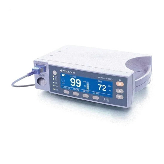
Nellcor OXIMAX N-595 Manuals
Manuals and User Guides for Nellcor OXIMAX N-595. We have
3
Nellcor OXIMAX N-595 manuals available for free PDF download: Operator's Manual, Service Manual
Nellcor OXIMAX N-595 Operator's Manual (184 pages)
Brand:
Nellcor
| Category:
Medical Equipment
| Size: 1.46 MB
Table of Contents
Table of Contents
3
Safety Information
11
Warnings
11
Cautions
12
Introduction
15
Intended Use for the N-595
15
How to Use this Manual
16
Figure 1: Front Panel Buttons and Symbols
17
Identification of Front Panel Buttons and Symbols
17
Description of Controls, Indicators, and Symbols
18
Identification of Rear Panel Components
18
N-595 Symbols
18
Figure 2: Rear Panel Components
18
Description of Controls
19
Description of Displays and Indicators
20
Description of Audible Indicators
24
Table 1: Audible Indicators
24
Setting up the Monitor
25
List of Components
27
Connecting the N-595 to AC Power
27
Connecting an OXI
29
MAX Sensor to the N-595
29
Battery Operation
31
Operating the N-595 on Battery Power
31
Low Battery Indicator
32
Table 2: Low Battery and Critical Battery
33
Introduction
37
Table 3: Parameter Ranges
37
Using the Monitor
37
Turning on the Monitor
39
OXI MAX Sensor Attached
41
No OXI MAX Sensor Attached
43
Turning the Backlight on or off
44
Adjusting Screen Contrast
44
Selecting the Pleth View
44
Selecting the Blip View
45
Setting the Pulse Beep Volume
46
Setting the Alarm Volume
46
Setting the Date and Time
47
Setting Alarm Silence Duration
48
Disabling Audible Alarms
49
Selecting Standby Mode
51
Adult-Pediatric or Neonatal Settings
52
Setting Patient Adult-Pediatric/Neonatal Mode
52
Alarm Limit Changed Indicator
54
Setting Alarm Limits
54
Setting Satseconds Alarm Limit
56
Setting Monitor Response Mode
57
Selecting the Display Language
58
OXI MAX Sensor Messages
59
OXI MAX Sensor Adjust Condition Messages
60
AX Sensor Adjust Messages
61
Monitor Trend
63
Monitor Trend Data
63
Trend Data Operation
65
Selecting the Trend Data Display Scale
65
Reading the Trend Data Display
67
Table 4: Reading Trend Display
67
Dual Trend Data Display
68
Spo2 Trend Display
69
Pulse Rate Trend Display
69
Histogram Trend Data Display
70
Pulse Amplitude Trend Data Display
71
Clearing Trend Information
72
OXI MAX Sensor Event Record
75
Setting In-Sensor Data Type
76
AX Sensor Type
78
AX Sensor Data Type
78
OXI MAX Sensor Event Record Data Available
79
MAX Sensor Event Record Not Available
80
OXI MAX Sensor Event Record Graphical Data
81
Viewing and Printing OXI MAX Sensor Event History Data
83
OXI MAX Sensor Tabular Event Data
85
Viewing and Printing In-Sensor Tabular Event History Data
86
Printing
89
Printing Monitor Trend Information
89
Monitor Trend Data in ASCII Mode
91
Trend Data in Graph Mode
92
Figure 3: ASCII Mode Printout
92
Real-Time Display/Printout Format
93
Figure 4: Graph Mode Printout
93
Figure 5: Real-Time Printout
94
Column Headings
95
Data Source
95
Software Version
95
Alarm Limits
96
Monitor Mode
96
Response Mode
96
Data Column Headings
97
Patient Data
97
Time
97
Operating Status
98
Using the Data Port
101
Overview
101
Connecting to the Data Port
101
Data Port Pinouts
102
Table 5: Data Port Pinouts
102
Data Port Setup
103
Figure 6: Data Port Pin Layout
103
Using the Nurse Call Interface
105
Setting Nurse Call RS-232 Polarity
106
Setting Nurse Call Relays Normally Open/Closed
107
Calculating the Analog Voltage Output
107
Table 6: Analog Pinouts
107
OXI MAX Sensors and Accessories
109
OXI MAX Sensor Event Record Data
109
Selecting an OXI MAX Sensor
109
Table 7: Nellcor OXIMAX Sensor Models and Patient Sizes
111
OXI MAX Sensor Features
113
Biocompatibility Testing
113
Optional Accessories
113
Table 8: OXIMAX Sensor Features
113
Figure 7: GCX Mounting Plate
115
GCX Mounting Plate
115
19-Inch Channel)
116
Figure 8: GCX Poly-Mount (Vertical Wall Mount with 19-Inch Channel)
116
GCX Poly-Mount
116
Figure 9: GCX Poly-Mount (Horizontal Wall Mount with Rail Adapter)
117
GCX Poly-Mount (Horizontal Wall Mount with Rail Adapter)
117
Figure 10: GCX Poly-Mount Roll Stand
118
GCX Poly-Mount Roll Stand
118
Figure 11: GCX Utility Basket
119
GCX Utility Basket
119
Figure 12: Soft-Sided Carrying Case
120
Soft-Sided Carrying Case
120
Performance Considerations
121
Performance Verification
121
Monitor Performance Considerations
121
Dysfunctional Hemoglobins
122
Anemia
122
Saturation
122
Pulse Rates
122
OXI MAX Sensor Performance Considerations
123
Troubleshooting
127
Error Codes
127
Table 9: Error Codes
128
Prompts and Error Messages
129
Table 10: Prompt/Error Messages
130
Corrective Action
132
EMI (Electro-Magnetic Interference)
135
Obtaining Technical Assistance
136
OXI MAX Sensor Message Setup
137
Maintenance
139
Returning the N-595
139
Service
139
Periodic Safety Checks
140
Cleaning
140
Menu Structure
141
N-595 Menu Description
141
Satseconds
145
Describing Satseconds
145
Figure 13: Alarm Response with Satseconds
146
Satseconds "Safety Net
147
Satseconds Display
147
Factory Defaults
149
Neonate Default Settings
149
Table 11: Neonate Factory Defaults
149
Adult Default Settings
150
Table 12: Adult Factory Defaults
150
Oximetry Overview
153
Automatic Calibration
154
Functional Versus Fractional Saturation
154
Measured Versus Calculated Saturation
155
Principles of Operation
153
OXI MAX Technology
155
Figure 14: Oxyhemoglobin Dissociation Curve
155
Performance
157
Specifications
157
Electrical
158
Environmental Conditions
159
Physical Characteristics
161
Compliance
162
Manufacturer's Declaration
165
Table 13: Electromagnetic Emissions
165
Table 14: Electromagnetic Immunity
166
Table 15: Electromagnetic Immunity, RF Portable Equipment
169
Table 16: Recommended Separation Distances
171
Table 17: Cables
172
Index
177
Advertisement
Nellcor OXIMAX N-595 Service Manual (160 pages)
Brand:
Nellcor
| Category:
Medical Equipment
| Size: 6.27 MB
Table of Contents
Table of Contents
3
Introduction
9
Warnings
9
Cautions
10
Manual Overview
10
Description of N-595 Monitor
11
Front Panel
12
Rear Panel
12
Figure 1: N-595 Front Panel
12
Figure 2: N-595 Rear Panel
12
Softkey Menu
13
Related Documents
16
Routine Maintenance
17
Cleaning
17
Periodic Safety Checks
17
Functional Checks
17
Battery
18
Performance Verification
19
Introduction
19
Equipment Needed
19
Performance Tests
19
Table 1: Equipment Needed
19
Battery Charge
20
Power-Up Performance
20
Operational Setup
25
General Operation
32
Pulse Oximetry Functional Tests
34
Figure 3: SRC-MAX OXIMAX Oximetry Tester
34
Safety Tests
41
Power-On Settings and Service Functions
43
Introduction
43
Power-On Settings
43
Factory Default Settings
43
Neonate Default Settings
43
Table 2: Neonate Alarm Limit Factory Defaults
43
Adult Default Settings
45
Service Functions
45
Table 3: Adult Alarm Factory Defaults
45
Accessing the Service Functions
46
Exit Softkey
47
Next Softkey
47
Param Softkey Menu
48
Print Softkey Menu
49
Next Softkey Menu
53
Setting Institutional Defaults (Sample)
55
Troubleshooting
59
Introduction
59
How to Use this Section
59
Who Should Perform Repairs
59
Troubleshooting Guide
59
Table 4: Problem Categories
60
Power
61
Table 5: Power Problems
61
Buttons
62
Table 6: Button Problems
62
Display/Alarms
63
Table 7: Display/Alarms Problems
63
Operational Performance
64
Table 8: Operational Performance Problems
64
Data Port
65
Error Codes
65
Table 9: Data Port Problems
65
Table 10: Error Codes
66
Other Messages
68
Disassembly Guide
71
Introduction
71
Replacement Level Supported
71
Prior to Disassembly
72
Fuse Replacement
72
Figure 4: Fuse Removal
72
Monitor Disassembly
73
Figure 5: Corner Screws
73
Monitor Assembly
74
Figure 6: Separating Case Halves
74
Battery Replacement
75
Removal
75
Figure 7: Removing the Battery
75
Replacement
76
Power Entry Module (PEM) Removal/Replacement
76
Removal
76
Replacement
77
Figure 8: Power Entry Module
77
Power Supply Removal/Replacement
78
Removal
78
Replacement
79
Figure 9: Power Supply
79
Table 11: Power Supply Lead Connections
79
Cooling Fan Removal/Replacement
80
Removal
80
Replacement
81
Figure 10: Cooling Fan
81
Display PCB Removal/Replacement
82
Removal
82
Replacement
83
Figure 11: Display PCB
83
User Interface PCB Removal/Replacement
84
Removal
84
Replacement
85
Figure 12: User Interface PCB
85
Alarm Speaker Removal/Replacement
86
Removal
86
Replacement
87
Figure 13: Alarm Speaker
87
Top Case Assembly Removal/Replacement
88
Removal
88
Replacement
88
Spare Parts
89
Introduction
89
Obtaining Replacement Parts
89
Parts List
90
Table 12: Parts List
90
Figure 14: Exploded View
91
Packing for Shipment
93
Introduction
93
Returning the N-595
93
General Instructions
93
Repacking in Original Carton
93
Figure 15: Packing
94
Repacking in a Different Carton
95
Specifications
97
Performance
97
Electrical
98
Environmental Conditions
98
Physical Characteristics
100
Compliance
101
Manufacturer's Declaration
103
Table 13: Electromagnetic Emissions
103
Table 14: Electromagnetic Immunity
104
Table 15: Electromagnetic Immunity, Portable RF Equipment
106
Table 16: Recommended Separation Distances
107
Table 17: Cables
108
Safety Tests
109
Ground Integrity
109
Earth Leakage Current
110
Enclosure Leakage Current
110
Patient Applied Risk Current
110
Patient Isolation Risk Current
112
Data Port Interface Protocol
113
Introduction
113
Configuring the Data Port
113
Communication Baud Rate
114
Communication Protocol
115
Language Selection
116
Nurse Call Setup
117
Analog Calibration Setup
118
Agilent (HP) Communications
119
Spacelabs Communications
119
Marquette Communications
120
Datex-Ohmeda Communications
121
Connecting to the Data Port
121
Table 18: Data Port Pin Outs
121
Figure 16: Data Port Pin Layout
122
Communication with a PC
123
Dump Instrument Info (Option 1)
123
Set Date and Time (Option 2)
123
Dump Trend (Option 3)
124
Dump Error Log (Option 4)
124
Exit Interactive Mode (Option 5)
124
Using Data on the PC
124
Real-Time Printout
125
Figure 17: Real-Time Printout
125
Column Heading
126
Patient Data and Operating Status
127
Table 19: Operating Status Codes
128
Trend Data Printout (ASCII Mode)
129
Trend Printout (Graph Mode)
129
Figure 18: Trend Data Printout (ASCII Mode)
129
Nurse Call
130
Figure 19: Monitor Trend Data Printout (Graph Mode)
130
Figure 20: Sensor Event Record Printout (Graph Mode)
130
Analog Output
131
Table 20: Nurse Call Relay Pin States
131
Table 21: Rating of Nurse Call Relay
131
Technical Discussion
133
Oximetry Overview
133
Functional Versus Fractional Saturation
133
Measured Versus Calculated Saturation
134
Satseconds Alarm Management
134
Figure 21: Oxyhemoglobin Dissociation Curve
134
Reads through Motion
135
OXIMAX Technology
135
Block Diagram Theory
136
Figure 22: Block Diagram
136
Figure 23: Main PCB Schematic Diagram (Sheet 1 of 13)
139
Figure 24: Main PCB Schematic Diagram (Sheet 2 of 13)
141
Figure 25: Main PCB Schematic Diagram (Sheet 3 of 13)
143
Figure 26: Main PCB Schematic Diagram (Sheet 4 of 13)
145
Figure 27: Main PCB Schematic Diagram (Sheet 5 of 13)
147
Figure 28: Main PCB Schematic Diagram (Sheet 6 of 13)
149
Figure 29: Main PCB Schematic Diagram (Sheet 7 of 13)
151
Figure 30: Main PCB Schematic Diagram (Sheet 8 of 13)
153
Main PCB Assembly Drawing (Rear View)
153
Linear Power Supply Schematic Diagram
154
Figure 31: Main PCB Schematic Diagram (Sheet 9 of 13)
155
Linear Power Supply Assembly Drawing
155
Figure 32: Main PCB Schematic Diagram (Sheet 10 of 13)
157
Figure 33: Main PCB Schematic Diagram (Sheet 11 of 13)
159
Nellcor OXIMAX N-595 Service Manual (147 pages)
Brand:
Nellcor
| Category:
Medical Equipment
| Size: 5.57 MB
Table of Contents
Table of Contents
3
Introduction
9
Warnings
9
Cautions
10
Manual Overview
10
Description of N-595 Monitor
10
Figure 1: N-595 Front Panel
11
Figure 2: N-595 Rear Panel
12
Figure 3: Limits Softkey Map
12
Figure 4: Trend Softkey Map
13
Related Documents
14
Figure 5: Setup Softkey Map
14
Routine Maintenance
15
Cleaning
15
Periodic Safety Checks
15
Functional Checks
15
Battery
16
Performance Verification
17
Introduction
17
Equipment Needed
17
Performance Tests
17
Table 1: Equipment Needed
17
Battery Charge
18
Power-Up Performance
18
Operational Setup
23
General Operation
29
Pulse Oximetry Functional Tests
31
Initial Setup
32
Safety Tests
36
Power-On Settings and Service Functions
37
Introduction
37
Power-On Settings
37
Factory Default Settings
37
Neonate Default Settings
37
Table 2: Neonate Alarm Limit Factory Defaults
37
Adult Default Settings
38
Table 3: Adult Alarm Factory Defaults
38
Service Functions
39
Accessing the Service Functions
39
Exit Softkey
41
Next Softkey
41
Param Softkey Menu
41
Figure 6: Service Function Menu
41
Print Softkey Menu
42
Next Softkey Menu
45
Setting Institutional Defaults (Sample)
48
Troubleshooting
51
Introduction
51
How to Use this Section
51
Who Should Perform Repairs
51
Troubleshooting Guide
51
Table 4: Problem Categories
51
Power
52
Table 5: Power Problems
52
Buttons
53
Table 6: Button Problems
53
Display/Alarms
54
Table 7: Display/Alarms Problems
54
Operational Performance
55
Table 8: Operational Performance Problems
55
Data Port
56
Error Codes
56
Table 9: Data Port Problems
56
Other Messages
57
Table 10: Error Code Problems
57
Disassembly Guide
59
Introduction
59
Replacement Level Supported
59
Prior to Disassembly
60
Fuse Replacement
60
Figure 7: Fuse Removal
60
Monitor Disassembly
61
Figure 8: Corner Screws
61
Monitor Assembly
62
Figure 9: Separating Case Halves
62
Battery Replacement
63
Removal
63
Figure 10: Removing the Battery
63
Replacement
64
Power Entry Module (PEM) Removal/Replacement
64
Removal
64
Replacement
65
Figure 11: Power Entry Module
65
Power Supply Removal/Replacement
66
Removal
66
Replacement
67
Figure 12: Power Supply
67
Table 11: Power Supply Lead Connections
67
Cooling Fan Removal/Replacement
68
Removal
68
Replacement
69
Figure 13: Cooling Fan
69
Display PCB Removal/Replacement
70
Removal
70
Replacement
71
Figure 14: Display PCB
71
User Interface PCB Removal/Replacement
72
Removal
72
Replacement
73
Figure 15: User Interface PCB
73
Alarm Speaker Removal/Replacement
74
Removal
74
Replacement
75
Figure 16: Alarm Speaker
75
Spare Parts
77
Introduction
77
Obtaining Replacement Parts
77
Parts List
77
Table 12: Parts List
77
Figure 17: Exploded View
78
Packing for Shipment
79
Introduction
79
Returning the N-595
79
General Instructions
79
Repacking in Original Carton
79
Figure 18: Packing
80
Repacking in a Different Carton
81
Specifications
83
Performance
83
Electrical
84
Environmental Conditions
84
Physical Characteristics
86
Compliance
86
Manufacturer's Declaration
88
Table 13: Electromagnetic Emissions (IEC 60601-1-2)
88
Table 14: Electromagnetic Immunity (IEC 60601-1-2)
89
Table 15: Electrostatic Immunity (IEC 60601-1-2)
91
Table 16: Recommended Separation Distances
92
Table 17: Cables (IEC 60601-1-2)
93
Safety Tests
94
Ground Integrity
94
Earth Leakage Current
94
Enclosure Leakage Current
95
Patient Applied Risk Current
95
Patient Isolation Risk Current
95
Data Port Interface Protocol
97
Introduction
97
Configuring the Data Port
97
Figure 19: Data Port Setup
98
Communication Baud Rate
99
Communication Protocol
99
Language Selection
100
Nurse Call Setup
101
Analog Calibration Setup
102
Agilent (HP) Communications
103
Spacelabs Communications
103
Datex-Ohmeda Communications
104
Marquette Communications
104
Connecting to the Data Port
105
Table 18: Data Port Pin Outs
105
Communication with a PC
106
Figure 20: Data Port Pin Layout
106
Dump Instrument Info (Option 1)
107
Dump Trend (Option 3)
107
Set Date and Time (Option 2)
107
Dump Error Log (Option 4)
108
Exit Interactive Mode (Option 5)
108
Using Data on the PC
108
Real-Time Printout
108
Column Heading
109
Figure 21: Real-Time Printout
109
Alarm Limits
110
Patient Data and Operating Status
111
Trend Data Printout (ASCII Mode)
112
Table 19: Operating Status Codes
112
Trend Printout (Graph Mode)
113
Nurse Call
113
Figure 22: Trend Data Printout (ASCII Mode)
113
Figure 23: Monitor Trend Data Printout (Graph Mode)
113
Figure 24: In-Sensor Event Trend Data Printout (Graph Mode)
113
Analog Output
114
Table 20: Nurse Call Relay Pin States
114
Table 21: Rating of Nurse Call Relay
114
Technical Discussion
117
Oximetry Overview
117
Automatic Calibration
118
Functional Versus Fractional Saturation
118
Measured Versus Calculated Saturation
118
Satseconds Alarm Management
119
Reads through Motion
119
OXIMAX Technology
119
Figure 25: Oxyhemoglobin Dissociation Curve
119
Block Diagram Theory
121
Figure 26: Block Diagram
121
Schematic Diagrams and Assembly Drawings
123
Advertisement
Advertisement
Related Products
Nellcor OxiMax N 5500
Nellcor OXIMAX N-560
Nellcor OxiMax N-550B
Nellcor Oximax NPB-40
Nellcor OxiMax N-65
Nellcor N-20P
Nellcor N-20
Nellcor N-395
Nellcor OXIMAX N-600X Series
Nellcor N-180
Nellcor Categories
Medical Equipment
Measuring Instruments
Security Sensors
Blood Pressure Monitor
Microphone
More Nellcor Manuals
Login
Sign In
OR
Sign in with Facebook
Sign in with Google
Upload manual
Upload from disk
Upload from URL