
Related Manuals for Gestetner A265


Summary of Contents for Gestetner A265
- Page 1 CÓPIA NÃO CONTROLADA A265/A267 SERVICE MANUAL 000882MIU RICOH GROUP COMPANIES CÓPIA NÃO CONTROLADA...
- Page 2 CÓPIA NÃO CONTROLADA CÓPIA NÃO CONTROLADA...
- Page 3 CÓPIA NÃO CONTROLADA Š Š RICOH GROUP COMPANIES CÓPIA NÃO CONTROLADA...
- Page 4 CÓPIA NÃO CONTROLADA CÓPIA NÃO CONTROLADA...
- Page 5 CÓPIA NÃO CONTROLADA A265/A267 SERVICE MANUAL 000882MIU CÓPIA NÃO CONTROLADA...
- Page 6 CÓPIA NÃO CONTROLADA CÓPIA NÃO CONTROLADA...
- Page 7 CÓPIA NÃO CONTROLADA It is the reader's responsibility when discussing the information contained within this document to maintain a level of confidentiality that is in the best interest of Ricoh Corporation and its member companies. NO PART OF THIS DOCUMENT MAY BE REPRODUCED IN ANY FASHION AND DISTRIBUTED WITHOUT THE PRIOR PERMISSION OF RICOH CORPORATION.
- Page 8 CÓPIA NÃO CONTROLADA CÓPIA NÃO CONTROLADA...
- Page 9 CÓPIA NÃO CONTROLADA WARNING Service Manual contains information regarding service techniques, procedures, processes and spare parts of office equipment distributed by Ricoh Corporation. Users of this manual should be either service trained or certified by successfully completing a Ricoh Technical Training Program. Untrained uncertified users...
- Page 10 CÓPIA NÃO CONTROLADA CÓPIA NÃO CONTROLADA...
- Page 11 CÓPIA NÃO CONTROLADA LEGEND PRODUCT CODE COMPANY GESTETNER LANIER RICOH SAVIN A265 3222 5222 Aficio 220 9922DP A267 3227 5227 Aficio 270 9927DP DOCUMENTATION HISTORY REV. NO. DATE COMMENTS 12/99 Original Printing CÓPIA NÃO CONTROLADA...
- Page 12 CÓPIA NÃO CONTROLADA CÓPIA NÃO CONTROLADA...
-
Page 13: Table Of Contents
Image Processing Modes ..............2-9 Image Processing Path............... 2-11 SP Modes for Each Image Processing Step........2-12 Auto Shading ..................2-18 White Line Erase Compensation ............2-18 Black Line Erase Compensation............2-18 Scanner Gamma (γ Correction ............2-19 A265/A267 CÓPIA NÃO CONTROLADA... - Page 14 ID sensor .................... 2-50 TD Sensor ..................2-50 2.6.8 TONER NEAR END/END DETECTION AND RECOVERY.... 2-50 Toner Near End Detection ..............2-50 Toner Near End Recovery ..............2-51 Toner End Detection................2-51 Toner End Recovery................2-51 A265/A267 CÓPIA NÃO CONTROLADA...
- Page 15 2.11.3 LOW POWER MODE ..............2-79 Entering the low power mode ............. 2-79 What happens in low power mode............2-79 Return to stand-by mode ..............2-79 2.11.4 AUTO OFF MODE................ 2-80 Entering auto off mode ............... 2-80 A265/A267 CÓPIA NÃO CONTROLADA...
- Page 16 3.10.1 ACCESSORY CHECK ..............3-30 3.10.2 INSTALLATION PROCEDURE ............ 3-31 3.11 BRIDGE UNIT INSTALLATION............. 3-33 3.11.1 ACCESSORY CHECK ..............3-33 3.11.2 INSTALLATION PROCEDURE ............ 3-33 3.12 1,000-SHEET FINISHER INSTALLATION ..........3-35 3.13 COPIER FEATURE EXPANDER INSTALLATION........ 3-38 A265/A267 CÓPIA NÃO CONTROLADA...
- Page 17 4.2.12 APS AND PLATEN/DF COVER SENSOR OUTPUT DISPLAY (SP4-301) ..................4-76 4.2.13 DF APS SENSOR OUTPUT DISPLAY (SP6-901) ....... 4-77 4.2.14 NIP BAND WIDTH MEASUREMENT ........... 4-78 4.2.15 DISPLAY LANGUAGE (SP5-808) ..........4-79 4.2.16 SERIAL NUMBER INPUT (SP5-811) ........... 4-79 A265/A267 CÓPIA NÃO CONTROLADA...
- Page 18 6.2.4 LD UNIT..................6-12 6.2.5 LASER SYNCHRONIZATION DETECTOR........6-13 6.3 PHOTOCONDUCTOR UNIT (PCU) ............6-14 6.3.1 PCU ....................6-14 6.4 TRANSFER UNIT..................6-15 6.4.1 TRANSFER ROLLER UNIT............6-15 6.4.2 IMAGE DENSITY SENSOR ............6-16 6.5 FUSING/EXIT ..................6-17 6.5.1 FUSING UNIT.................6-17 6.5.2 THERMISTOR................6-17 6.5.3 THERMOFUSE ................6-18 A265/A267 CÓPIA NÃO CONTROLADA...
- Page 19 SC194: IPU White Level Detection Error ..........7-4 SC546: Unstable fusing temperature ........... 7-9 SC620: Communication error between IOB and ADF ......7-10 SC760: ADF gate abnormal ............... 7-14 SC900: Electrical total counter error ..........7-14 SC901: Mechanical Total Counter ............. 7-14 A265/A267 CÓPIA NÃO CONTROLADA...
- Page 20 1.6 CONDITION OF JAM DETECTION ............8-18 1.7 OVERALL ELECTRICAL CIRCUIT............8-19 3. REPLACEMENT AND ADJUSTMENT........8-20 3.1 DF EXIT TABLE AND COVER ............... 8-20 3.2 ORIGINAL FEED UNIT................8-21 3.3 LEFT COVER ..................8-22 A265/A267 viii CÓPIA NÃO CONTROLADA...
-
Page 21: Paper Tray Unit A
3.5 UPPER PAPER FEED CLUTCH REPLACEMENT......... 9-17 3.6 LOWER PAPER FEED CLUTCH REPLACEMENT........ 9-18 3.7 LIFT MOTOR REPLACEMENT .............. 9-19 3.8 PAPER END SENSOR REPLACEMENT ..........9-20 3.9 VERTICAL TRANSPORT SENSOR REPLACEMENT ......9-20 3.10 PAPER SIZE SWITCH REPLACEMENT..........9-21 A265/A267 CÓPIA NÃO CONTROLADA... -
Page 22: Large Capacity Tray A
2.1 BASIC OPERATION ................11-3 2.2 PAPER SIZE DETECTION ..............11-4 3 REPLACEMENT AND ADJUSTMENT ........... 11-5 3.1 PAPER FEED ROLLER/FRICTION PAD/PAPER END SENSOR ..11-5 3.2 PAPER SIZE SENSOR BOARD ............. 11-6 3.3 PAPER FEED CLUTCH ................11-7 A265/A267 CÓPIA NÃO CONTROLADA... -
Page 23: Interchange Unit B
3.2 ENTRANCE SENSOR REPLACEMENT..........13-10 3.3 EXIT SENSOR REPLACEMENT ............13-11 1 BIN TRAY UNIT A898 1. OVERALL INFORMATION ............14-1 1.1 SPECIFICATIONS .................. 14-1 1.2 MECHANICAL COMPONENT LAYOUT ..........14-2 1.3 ELECTRICAL COMPONENT LAYOUT........... 14-3 A265/A267 CÓPIA NÃO CONTROLADA... -
Page 24: Bridge Unit A
3.1 TRAY COVER REPLACEMENT ............. 16-6 3.1.1 TRAY COVER REMOVAL.............. 16-6 3.1.2 TRAY COVER ATTACHMENT............16-6 3.2 TRAY MOTOR AND HALF TURN SENSOR REPLACEMENT ....16-7 3.2.1 REPLACING THE TRAY MOTOR..........16-7 3.2.2 REPLACING THE HALF TURN SENSOR: ........16-7 A265/A267 CÓPIA NÃO CONTROLADA... -
Page 25: Finisher A
Rear Shift Tray Cover ...............17-19 Shift Tray...................17-19 4.2 ENTRANCE SENSOR REPLACEMENT ..........17-20 4.3 EXIT SENSOR REPLACEMENT ............17-21 4.4 STACK HEIGHT SENSOR REPLACEMENT ........17-22 4.5 POSITIONING ROLLER REPLACEMENT ..........17-23 4.6 STAPLER REPLACEMENT..............17-24 4.7 ROM HISTORY ..................17-25 xiii A265/A267 CÓPIA NÃO CONTROLADA... -
Page 26: Scanner Kit A
5.1 NOTE FOR REPLACING THE SCANNER CONTROLLER BOARD..18-13 6. TROUBLESHOOTING.............. 18-14 6.1 SERVICE CALL CONDITION ..............18-14 6.1.1 SC CODE DESCRIPTIONS............18-14 6.2 LEDS ..................... 18-15 6.3 FIRMWARE HISTORY ................18-16 6.3.4 A844 FIRMWARE MODIFICATION HISTORY ......18-16 A265/A267 CÓPIA NÃO CONTROLADA... -
Page 27: Important Safety Notices
CÓPIA NÃO CONTROLADA IMPORTANT SAFETY NOTICES PREVENTION OF PHYSICAL INJURY 1. Before disassembling or assembling parts of the copier and peripherals, make sure that the copier power cord is unplugged. 2. The wall outlet should be near the copier and easily accessible. 3. -
Page 28: Laser Safety
CÓPIA NÃO CONTROLADA LASER SAFETY The Center for Devices and Radiological Health (CDRH) prohibits the repair of laser-based optical units in the field. The optical housing unit can only be repaired in a factory or at a location with the requisite equipment. The laser subsystem is replaceable in the field by a qualified Customer Engineer. -
Page 29: Overall Information
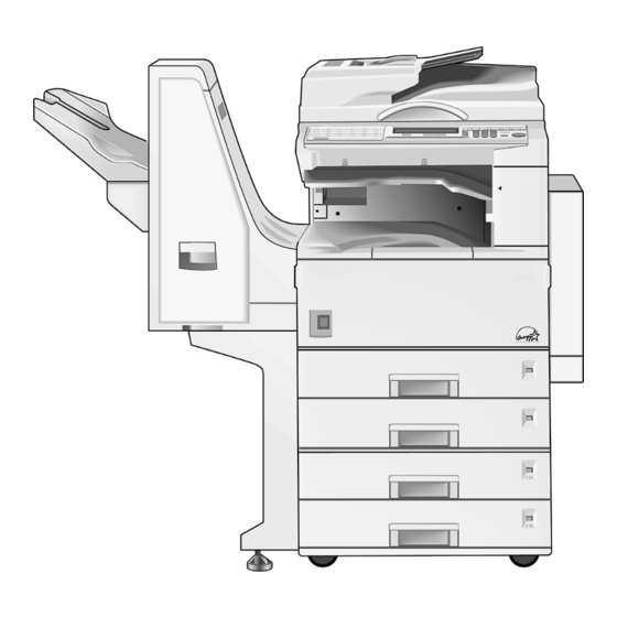
CÓPIA NÃO CONTROLADA OVERALL INFORMATION PAPER TRAY UNIT A860 FINISHER A681 DETAILED DESCRIPTIONS LARGE CAPACITY TRAY A862 SCANNER KIT A844 INSTALLATION BY-PASS UNIT A899 FAX UNIT A895 SERVICE TABLES INTERCHANGE UNIT B300 ISDN UNIT A895 PREVENTIVE MAINTENANCE DUPLEX A896 PRINTER CONTROLLER B306 REPLACEMENT AND ADJUSTMENT 1 BIN TRAY UNIT A898 NETWORK INTERFACE BOARD B307... - Page 30 CÓPIA NÃO CONTROLADA CÓPIA NÃO CONTROLADA...
-
Page 31: Overall Machine Information
CÓPIA NÃO CONTROLADA OVERALL MACHINE INFORMATION CÓPIA NÃO CONTROLADA... - Page 32 CÓPIA NÃO CONTROLADA CÓPIA NÃO CONTROLADA...
-
Page 33: Specifications
60 ~ 157 g/m , 16 ~ 42 lb Reproduction Ratios: 5 Enlargement and 7 Reduction A4/A3 Version LT/DLT Version 400% 400% 200% 200% 141% 155% Enlargement 122% 129% 115% 121% Full Size 100% 100% Reduction A265/A267 CÓPIA NÃO CONTROLADA... - Page 34 Operating (Full System): 67.5 dB(A) NOTE: 1) The above measurements were made in accordance with ISO 7779. 2) Full System: Mainframe + ADF + 1-bin Sorter + Paper Tray Unit + Duplex Unit + Bridge Unit + Finisher A265/A267 CÓPIA NÃO CONTROLADA...
- Page 35 1) When the polygonal mirror motor is spinning. 2) From the 1st paper tray 3) Not APS mode 4) Full size Copy Number Input: Ten-key pad, 1 to 99 (count up or count down) Manual Image Density: 7 steps A265/A267 CÓPIA NÃO CONTROLADA...
- Page 36 10 k copies (A4 sideways, 6% full black, 1 to 1 copying, ADS mode) Copy Tray Capacity: Copy Tray: 500 sheets (without 1-bin tray) 250 sheets (with 1-bin tray) Memory Capacity: Standard 20 MB, Optional memory 48 MB A265/A267 CÓPIA NÃO CONTROLADA...
-
Page 37: Machine Configuration
CÓPIA NÃO CONTROLADA MACHINE CONFIGURATION 1.2 MACHINE CONFIGURATION 1.2.1 SYSTEM COMPONENTS A265V501.WMF A265/A267 CÓPIA NÃO CONTROLADA... - Page 38 CÓPIA NÃO CONTROLADA MACHINE CONFIGURATION Version Item Machine Code Copier Copier A265 Copier A267 ARDF (Optional) A858 Platen Cover (Optional) A893 Paper Tray Unit - 2 tray (Optional) A860-11, -21, LCT (Optional) A862 1-bin Tray (Optional) A898 Shift Tray (Optional)
-
Page 39: Installable Option Table
CÓPIA NÃO CONTROLADA Rev. 03/2000 MACHINE CONFIGURATION 1.2.2 INSTALLABLE OPTION TABLE Copier options Option A265/A267 Note ARDF (Optional) Install either no. 1 or 2 Platen Cover (Optional) Install either no. 1 or 2 Paper Tray Unit - 2 tray (Optional) Install either no. -
Page 40: Paper Path
1.3 PAPER PATH A267V102.WMF 1. Optional ADF 2. Optional 1-bin Tray 3. Optional Interchange Unit 4. Optional Duplex Unit 5. Optional By-pass Feed Tray 6. Optional Paper Tray Unit 7. Optional 1000-sheet Finisher 8. Optional Bridge Unit A265/A267 CÓPIA NÃO CONTROLADA... -
Page 41: Mechanical Component Layout
CÓPIA NÃO CONTROLADA MECHANICAL COMPONENT LAYOUT 1.4 MECHANICAL COMPONENT LAYOUT A265V100.WMF A265/A267 CÓPIA NÃO CONTROLADA... - Page 42 25. Laser unit 11. Fusing pressure roller 26. Toner supply bottle holder 12. Cleaning unit 27. Drum charge roller 13. OPC drum 28. Anti-condensation heater 14. Transfer roller 29. Scanner home position sensor 15. Development roller A265/A267 1-10 CÓPIA NÃO CONTROLADA...
-
Page 43: Electrical Component Descriptions
Cuts the +5VLD and +24V dc power line and Front Cover Safety detects whether the front cover is open or not. Provides power for machine operation. The SW10 Operation machine still has power if this switch is off. 1-11 A265/A267 CÓPIA NÃO CONTROLADA... - Page 44 Contains the CCD, and outputs a video signal to PCB4 SBU (Sensor Board Unit) the BICU board. PCB5 Lamp Stabilizer Stabilizes the power to the exposure lamp. PCB6 LDD (Laser Diode Driver) Controls the laser diode. PCB7 Operation Panel Controls the operation panel. A265/A267 1-12 CÓPIA NÃO CONTROLADA...
- Page 45 Mechanical Counter Keeps track of the total number of prints made. Used for control of authorized use. If this feature is Key Counter (Option) enabled for copying, copying will be impossible until it is installed. 1-13 A265/A267 CÓPIA NÃO CONTROLADA...
-
Page 46: Drive Layout
1.6 DRIVE LAYOUT Scanner A267V301.WMF Fusing PCU/Transfer Drive A267V302.WMF 1. Scanner Drive Motor 2. Main Motor 3. Registration Clutch 4. Upper Paper Feed Clutch 5. Upper Transport Clutch 6. Lower Paper Feed Clutch 7. Lower Transport Clutch A265/A267 1-14 CÓPIA NÃO CONTROLADA... -
Page 47: Copy Process
In the dark, the charge roller gives a negative charge to the organic photo- conductive (OPC) drum. The charge remains on the surface of the drum because the OPC layer has a high electrical resistance in the dark. 1-15 A265/A267 CÓPIA NÃO CONTROLADA... - Page 48 8. CLEANING The cleaning blade removes any toner remaining on the drum surface after the image transfers to the paper. 9. QUENCHING The light from the quenching lamp electrically neutralizes the charge on the drum surface. A265/A267 1-16 CÓPIA NÃO CONTROLADA...
-
Page 49: Board Structure
I O B P S U High Bridge Clutches/ Ther- Voltage B y - p a s s Duplex 1-Bin Tray Finisher S e n s o r s Motors Unit Solenoids mistor P . P A267V500.WMF 1-17 A265/A267 CÓPIA NÃO CONTROLADA... -
Page 50: Description
The SBU deals with the analog signals from the CCD and converts them into digital signals. 4. Mother Board (Option) This board interfaces the BICU with the printer controller and/or the scanner controller. The mother board is part of the expansion box option. A265/A267 1-18 CÓPIA NÃO CONTROLADA... -
Page 51: Detailed Descriptions
CÓPIA NÃO CONTROLADA DETAILED DESCRIPTIONS CÓPIA NÃO CONTROLADA... - Page 52 CÓPIA NÃO CONTROLADA CÓPIA NÃO CONTROLADA...
-
Page 53: Detailed Section Descriptions
An optics anti-condensation heater [G] is available as an option. It can be installed on the left side of the scanner. It turns on whenever the power cord is plugged in and the main power switch is off. A265/A267 CÓPIA NÃO CONTROLADA... -
Page 54: Scanner Drive
BICU board, like for book mode. Magnification in the sub-scan direction can be adjusted by changing the ADF motor speed using SP6-007. In the main scan direction, it can be adjusted with SP4-008, like for book mode. A265/A267 CÓPIA NÃO CONTROLADA... -
Page 55: Original Size Detection In Platen Mode
APS sensors. If the copy is made with the platen fully open, the CPU decides the original size from the sensor outputs when the Start key is pressed. A265/A267 CÓPIA NÃO CONTROLADA... - Page 56 However, for each page, the data signal to the laser diode is stopped to match the copy paper length detected by the registration sensor. Original size detection using the ADF is described in the manual for the ADF. A265/A267 CÓPIA NÃO CONTROLADA...
-
Page 57: Image Processing
• LD controller: LD print timing control and laser power PWM control • FCI (inside the LD controller): Smoothing (binary picture processing mode only) The EMB board is the copier feature expander option, which provides extra memory for the copier features. A265/A267 CÓPIA NÃO CONTROLADA... -
Page 58: Sbu (Sensor Board Unit)
After the above processing, the analog signals are converted to 8-bit signals by the A/D converter. This will give a value for each pixel on a scale of 256 grades. Then, the digitized image data is sent to the BICU board. A265/A267 CÓPIA NÃO CONTROLADA... -
Page 59: Auto Image Density
If the user selects a “Service Mode” original type with the user tools, these two ADS process can be either enabled or disabled (SP4-936, SP4-937), and the amount of white level change for the IPU ADS process can be adjusted (SP4-938). A265/A267 CÓPIA NÃO CONTROLADA... -
Page 60: Ipu (Image Processing Unit)
4. Magnification 5. ID gamma correction 6. Grayscale processing 7. Binary picture processing 8. Error diffusion 9. Dithering 10. Video path control 11. Test pattern generation The image data then goes to the LD driver (LDD). A265/A267 CÓPIA NÃO CONTROLADA... -
Page 61: Image Processing Modes
UT mode) For details of the SP modes that can be used to adjust the image quality for all the original modes, see the “SP Modes for Each Image Processing Step” section. A265/A267 CÓPIA NÃO CONTROLADA... - Page 62 Service mode Default: Colored originals (with blue or green text or background) Photo Press print Fine-grained printed originals, with no text. Normal Normal photos Glossy Photo Glossy photos Service mode Default: Normal photos A265/A267 2-10 CÓPIA NÃO CONTROLADA...
-
Page 63: Image Processing Path
• Grayscale Processing Others • Independent Dot Erase • Line Width Correction • Printer Gamma Correction Optional Fax Unit Optional Video Path Control Printer Controller Optional Scanner Controller BICU LD Unit Binary Picture Processing Grayscale Processing A265D509.WMF 2-11 A265/A267 CÓPIA NÃO CONTROLADA... -
Page 64: Sp Modes For Each Image Processing Step
4-940-4 Gradation Error diffusion Binary picture processing Dynamic 4-922-1 Threshold Dynamic Dynamic 4-923 ~ 4-926 4-931 ~ 4-934 Independent Dot Erase None None (after image process) 4-939 Thinner Lines (medium) Line Width Correction Disabled 4-935-4 A265/A267 2-12 CÓPIA NÃO CONTROLADA... - Page 65 4-944 (Enable/disable) 4-917-1 Text ID γ Correction Text 4-940-1 Gradation Error diffusion Constant Threshold Constant 4-929-1 Independent Dot Erase None None (after image process) 4-939 Disabled Thick Thin Line Width Correction Disabled (Medium) (Medium) 4-935-1 2-13 A265/A267 CÓPIA NÃO CONTROLADA...
- Page 66 4-944 (Enable/disable) 4-917-4 Text Priority ID γ Correction Photo priority Text Priority 4-940-5 Gradation Error diffusion Constant Threshold Constant 4-922-2 4-929-4 Independent Dot Erase None (after image process) Thicker Lines Line Width Correction Disabled (strong) 4-935-5 A265/A267 2-14 CÓPIA NÃO CONTROLADA...
- Page 67 Independent Dot Erase 4-944 (Enable/disable) 4-917-2 Text priority ID γ Correction Text priority Photo priority 4-940-2 Gradation Error diffusion Constant Threshold Constant 4-929-2 Independent Dot Erase None (after image process) Thick Line Width Correction Disabled (Strong) 4-935-2 2-15 A265/A267 CÓPIA NÃO CONTROLADA...
- Page 68 Coarse print Press print Glossy photo 4-940-6 Dither Dither Dither Error Gradation (105 lines) (53 lines) (105 lines) diffusion 4-929-5 Threshold Constant Independent Dot Erase None (after image process) Disabled Line Width Correction Disabled 4-935-6 A265/A267 2-16 CÓPIA NÃO CONTROLADA...
- Page 69 Coarse print Press print Glossy photo 4-940-3 Dither Dither Dither Error (143 lines) Gradation (105 lines) (143 lines) diffusion 4-929-3 Threshold Dynamic Independent Dot Erase None (after image process) Disabled Line Width Correction Disabled 4-935-3 2-17 A265/A267 CÓPIA NÃO CONTROLADA...
-
Page 70: Auto Shading
This low output is corrected using neighboring pixels. To adjust or switch off this correction, use SP4-919 (for the original modes known as “Service Mode”) and SP4-943 (other original modes). A265/A267 2-18 CÓPIA NÃO CONTROLADA... - Page 71 • Reflection Ratio ID Linear (Linear): Uses the image data without correction. • Removed background (SP): Removes the background area completely and corrects the rest of the image data in proportion to the original density. Linear Output Original Density Removed Background A250D550.WMF 2-19 A265/A267 CÓPIA NÃO CONTROLADA...
-
Page 72: Main Scan Magnification/Reduction
ADF mode, the ADF feeds the leading edge of the original to the DF exposure glass, and the opposite top corner of the original is at the main scan start position. To create the mirror image, the IPU stores each line in a LIFO (Last In First Out) memory. A265/A267 2-20 CÓPIA NÃO CONTROLADA... -
Page 73: Filtering
A stronger MTF filter can make a low ID image visible but moiré may become more visible. Moiré is reduced using a smoothing filter specially designed for this purpose (see “Smoothing Filter Adjustment - Text/Photo”). 2-21 A265/A267 CÓPIA NÃO CONTROLADA... - Page 74 CÓPIA NÃO CONTROLADA IMAGE PROCESSING Grayscale Processing A265D510.WMF A265/A267 2-22 CÓPIA NÃO CONTROLADA...
- Page 75 CÓPIA NÃO CONTROLADA IMAGE PROCESSING Binary Picture Processing A265D511.WMF 2-23 A265/A267 CÓPIA NÃO CONTROLADA...
-
Page 76: Scanner Gamma
These independent dots are erased after gradation processing. SP4-939 changes the filter that is used for this process, and it can be also used to disable this feature. A smaller matrix is more likely to remove dots. A265/A267 2-24 CÓPIA NÃO CONTROLADA... -
Page 77: Id Gamma (Γ) Correction
Note that although the LDD can create 256 levels per pixel, the machine only uses 16 of these, and only four are used for any one job. A gamma table determines which four output levels are used. The gamma table is different for each original type setting. 2-25 A265/A267 CÓPIA NÃO CONTROLADA... - Page 78 In this case it is necessary to adjust the image density level with the image density key on the operation panel. These adjustments are only for binary picture processing mode. A265/A267 2-26 CÓPIA NÃO CONTROLADA...
-
Page 79: Line Width Correction
The line width correction is done in the IPU chip. The line width correction type can be selected with SP4-935. 2-27 A265/A267 CÓPIA NÃO CONTROLADA... -
Page 80: Memory Controller And Enhanced Memory Board (Emb)
20 MB + Optional Standard (20 MB) (68 MB total) A4 6% Binary picture processing ITU-T#4 (12% black) A4 6% Not available Grayscale processing ITU-T#4 (12% black) Not available [A4 size, Text mode (Number of pages)] A265/A267 2-28 CÓPIA NÃO CONTROLADA... -
Page 81: Video Control Unit (Vcu)
(e.g., the characteristics of the drum, laser diode, and lenses). The machine chooses the most suitable gamma curve for the original type selected by the user. There is no SP adjustment for this. 2-29 A265/A267 CÓPIA NÃO CONTROLADA... -
Page 82: Laser Exposure
[H]. The laser synchronizing detector [I] determines the main scan starting position. The speed of the polygon mirror motor is 28,818.9 rpm for 600 dpi. A265/A267 2-30 CÓPIA NÃO CONTROLADA... -
Page 83: Auto Power Control (Apc)
This auto power control is done just after the machine is turned on and during printing while the laser diode is active. The laser diode power is adjusted on the production line. NOTE: Do not touch the variable resistors on the LD unit in the field. 2-31 A265/A267 CÓPIA NÃO CONTROLADA... -
Page 84: Ld Safety Switch
The switches are installed on the +5VLD line coming from the power supply unit through the IOB and BICU boards. When the front cover or the right cover is opened, the power supply to the laser diode is interrupted. A265/A267 2-32 CÓPIA NÃO CONTROLADA... -
Page 85: Photoconductor Unit (Pcu)
The machine informs the user when the PCU life has finished. However, the user can continue to make copies. SP5-912 can be used to enable or disable this warning message, and to change the default replacement interval (the default is 60k). 2-33 A265/A267 CÓPIA NÃO CONTROLADA... -
Page 86: Drive
The fly-wheel [E] on the end of the drum drive shaft stabilizes the rotation speed (this prevents banding and jitter from appearing on copies). A265/A267 2-34 CÓPIA NÃO CONTROLADA... -
Page 87: New Pcu Detection
(in other words, it checks whether the technician remembered to remove the developer seal from the PCU at machine installation). If the machine does not detect the ID sensor pattern, SC 392 will be generated. 2-35 A265/A267 CÓPIA NÃO CONTROLADA... -
Page 88: Drum Charge
[A] always contacts the surface of the drum [B] to give it a negative charge of –900V. The high voltage supply board gives a negative dc voltage to the drum charge roller through the spring [C] and terminal plate [D]. A265/A267 2-36 CÓPIA NÃO CONTROLADA... -
Page 89: Charge Roller Voltage Correction
The ID sensor measures the density of this pattern [B], and the output voltage is known as Vsdp. This voltage is compared with Vsg (read from the bare drum at the same time). 2-37 A265/A267 CÓPIA NÃO CONTROLADA... -
Page 90: Id Sensor Pattern Production Timing
• During warming up at power on • If the machine starts warming up after a certain time (default: 30 minutes) has passed since entering night mode or low power mode The 30-minute interval can be changed using SP2-995. A265/A267 2-38 CÓPIA NÃO CONTROLADA... -
Page 91: Drum Charge Roller Cleaning
The pin [C] at the rear of the cleaning pad holder touches the cam gear [D], and this gear moves the cleaning pad from side to side. This movement improves the cleaning. 2-39 A265/A267 CÓPIA NÃO CONTROLADA... -
Page 92: Development
This machine uses a single-roller development system. Two mixing augers mix the developer. The toner density (TD) sensor and image density (ID) sensor (see the illustration in the PCU section) are used to control toner density. A265/A267 2-40 CÓPIA NÃO CONTROLADA... -
Page 93: Drive
[D]. When the PCU is pushed in, the development drive shaft engages the development roller gear. The development drive gears (except for the gears in the development unit) are helical gears. These gears are quieter than normal gears. 2-41 A265/A267 CÓPIA NÃO CONTROLADA... -
Page 94: Developer Mixing
[C] by the doctor blade [D], towards the front of the machine. Mixing auger 1 [B] returns the excess developer, along with new toner, to the rear of the mixing assembly. Here the developer is reapplied to the development roller. A265/A267 2-42 CÓPIA NÃO CONTROLADA... -
Page 95: Development Bias
-600 volts to the development rollers throughout the image development process. The bias is applied to the development roller shaft [A] through the drive shaft [B]. The development bias voltage (-600 V) can be adjusted with SP2-201-1. 2-43 A265/A267 CÓPIA NÃO CONTROLADA... -
Page 96: Toner Supply
• The chuck releases the toner bottle cap into its proper position. • The toner shutter shuts to block the opening as a result of pressure from a spring. A265/A267 2-44 CÓPIA NÃO CONTROLADA... -
Page 97: Toner Supply Mechanism
[D]. When the PCU is installed in the machine, the shutter [E] above the PCU is opened by the machine frame. Then the toner falls down into the development unit through the slit and the shutter. 2-45 A265/A267 CÓPIA NÃO CONTROLADA... -
Page 98: Toner Density Control
(Vsp/Vsg). Toner Supply Clutch On Time Calculation TD Sensor Output (Vt) Vt Reference Voltage (Vref) New Vref Vt Reference Voltage Update Vref Update ID Sensor Output (Vsp/Vsg) TD Sensor Initial Setting (Vts) A265D517.WMF A265/A267 2-46 CÓPIA NÃO CONTROLADA... - Page 99 Fixed control 2 (SP2-921, “3”): Use temporarily if the TD Mode sensor needs to be replaced Toner supply decision None Toner control process Toner is supplied every printed page regardless of Vt. Toner supply amount Fixed (SP2-925) Toner end detection Not performed 2-47 A265/A267 CÓPIA NÃO CONTROLADA...
-
Page 100: Toner Density Sensor Initial Setting
• (Vts or the current Vref) - Vt Toner supply determination The reference voltage (Vts or Vref) is the threshold voltage for determining whether or not to supply toner. If Vt becomes greater than the reference voltage, the machine supplies additional toner. A265/A267 2-48 CÓPIA NÃO CONTROLADA... -
Page 101: Toner Supply Motor On Time Determinations
2) The value of “T” can be changed using SP2-923 (default: 30 seconds) 3) T (30) means that toner is supplied intermittently in a 1/3 duty cycle (1 s on, 2 s off) for 30 seconds 2-49 A265/A267 CÓPIA NÃO CONTROLADA... -
Page 102: Toner Supply In Abnormal Sensor Conditions
Then the machine supplies toner for a certain time, which depends on the setting of SP 2-923 (see the previous page). A265/A267 2-50 CÓPIA NÃO CONTROLADA... -
Page 103: Toner Near End Recovery
If the front cover is opened and closed for 10 seconds while a toner end condition exists and the toner bottle is replaced, the machine attempts to recover using the same procedure as for toner near end/end detection. 2-51 A265/A267 CÓPIA NÃO CONTROLADA... -
Page 104: Drum Cleaning And Toner Recycling
[B]. To remove the toner and other particles that are accumulated at the edge of the cleaning blade, the drum turns in reverse for about 5 mm at the end of every copy job. A265/A267 2-52 CÓPIA NÃO CONTROLADA... -
Page 105: Toner Recycling
PCU. Then, this toner falls into the development unit with new toner coming from the toner bottle and it is all mixed together by mixing auger 1 [C] and used again. 2-53 A265/A267 CÓPIA NÃO CONTROLADA... -
Page 106: Paper Feed
3. Paper Height –2 Sensor 10. Special Paper Sensor 4. Paper End Sensor 11. Lower Relay Sensor 5. Paper Feed Roller 12. Friction Pad 6. Paper Size Sensor 13. Tray Heater (Option) 7. Upper Relay Sensor A265/A267 2-54 CÓPIA NÃO CONTROLADA... -
Page 107: Paper Feed Drive Mechanism
[C]. When the paper feed clutch turns on, the feed rollers start to feed the paper. The paper feed clutch stays on until shortly after the registration sensor [D] has been activated. 2-55 A265/A267 CÓPIA NÃO CONTROLADA... -
Page 108: Paper Feed And Separation Mechanism
The paper feed roller [A] drives the top sheet of paper from the paper tray to the copier. The friction pad [B] allows only one sheet to feed at a time. The friction pad applies pressure to the feed roller with a spring [C]. The friction pad pressure cannot be adjusted. A265/A267 2-56 CÓPIA NÃO CONTROLADA... -
Page 109: Paper Lift Mechanism
For smaller paper, it reverses the larger amount (600 ms) to reduce the pressure more. NOTE: The relationship between the bottom plate pressure adjustment, paper size thresholds, and the related SP modes is explained in “Bottom Plate Pressure Adjustment for Paper Size”. 2-57 A265/A267 CÓPIA NÃO CONTROLADA... -
Page 110: Paper End Detection
[C] in the tray bottom plate and the paper end sensor is activated. When the paper tray is drawn out with no paper in the tray, the shape of the paper end feeler causes it to lift up. A265/A267 2-58 CÓPIA NÃO CONTROLADA... -
Page 111: Paper Height Detection
NOTE: The relationship between the bottom plate re-adjustment timing, paper size threshold, and the related SP modes is explained in “Bottom Plate Pressure Adjustment for Paper Size”. 2-59 A265/A267 CÓPIA NÃO CONTROLADA... -
Page 112: Feed Pressure Adjustment For Paper Size
Normal paper size range: Paper sizes greater than the ‘Middle’ SP mode. For Two Size Ranges Small paper size range: Paper sizes equal to the ‘Small’ SP mode value, or smaller. Normal paper size range: Paper sizes greater than the ‘Small’ SP mode. A265/A267 2-60 CÓPIA NÃO CONTROLADA... -
Page 113: Feed Pressure Adjustment
1st paper tray SP1-908-1 SP1-908-2 SP1-908-3 2nd paper tray SP1-909-1 SP1-909-2 SP1-909-3 3rd paper tray SP1-910-1 SP1-910-2 SP1-910-3 4th paper tray SP1-911-1 SP1-911-2 SP1-911-3 Default (all trays) 200 ms 600 ms 200 ms (default: not used) 2-61 A265/A267 CÓPIA NÃO CONTROLADA... - Page 114 HLT/A5 or smaller None (default setting) (default setting) 1st paper tray SP1-908-6 SP1-908-7 2nd paper tray SP1-909-6 SP1-909-7 3rd paper tray SP1-910-6 SP1-910-7 4th paper tray SP1-911-6 SP1-911-7 Default (all trays) Near-end Near-end (default: not used) A265/A267 2-62 CÓPIA NÃO CONTROLADA...
-
Page 115: Paper Size Detection
When the paper size actuator is at the “*” mark, the paper tray can be set up to accommodate one of a wider range of paper sizes by using user tools. If the paper size for this position is changed without changing the user tool setting, a paper jam will result. 2-63 A265/A267 CÓPIA NÃO CONTROLADA... -
Page 116: Special Paper Setting
B4 width (10”): 15 µA A4 width (8.5”): 17 µA A5 width (5.5”): 20 µA Note that for the by-pass tray, the fusing and transfer conditions for special paper are also applied if the user uses thick (non-standard) mode. A265/A267 2-64 CÓPIA NÃO CONTROLADA... -
Page 117: Side And End Fences
The end fence [D] is connected to the bottom plate. When the tray bottom plate rises, the end fence moves forward and pushes the back of the paper stack to keep it squared up. 2-65 A265/A267 CÓPIA NÃO CONTROLADA... -
Page 118: Paper Registration
This may be needed when feeding thicker paper. This adjustment is made with SP 1-903; it can be adjusted separately for tray 1 and the by-pass feeder, so place the problem paper type in one of these and adjust SP 1-903 for that tray only. A265/A267 2-66 CÓPIA NÃO CONTROLADA... -
Page 119: Image Transfer And Paper Separation
The curvature of the drum and the discharge plate [C] help the paper to separate from the drum. The high voltage supply board also supplies a negative dc voltage to the discharge plate. Drive from the drum through a gear [D] turns the transfer roller 2-67 A265/A267 CÓPIA NÃO CONTROLADA... -
Page 120: Image Transfer Current Timing
Be careful when increasing the transfer current. This might cause a ghosting effect, in which part of the image at the top of the page is repeated lower down the page at a lower density. In the worst case, it may also damage the OPC drum. A265/A267 2-68 CÓPIA NÃO CONTROLADA... -
Page 121: Transfer Roller Cleaning
The high voltage supply board applies a constant dc voltage, -1.8 kV (when feeding from a paper tray) or –2.1 kV (from the duplex unit) to the discharge plate. The discharge plate voltage can be adjusted using SP2-901. 2-69 A265/A267 CÓPIA NÃO CONTROLADA... -
Page 122: Image Fusing And Paper Exit
1. Paper exit roller 7. Fusing lamp 2. Fusing exit sensor 8. Thermistor 3. Hot roller strippers 9. Hot roller 4. Pressure spring 10. Thermofuse 5. Cleaning roller 11. Paper overflow sensor lever 6. Pressure roller A265/A267 2-70 CÓPIA NÃO CONTROLADA... -
Page 123: Fusing Drive And Release Mechanism
The fusing unit release mechanism automatically disengages the fusing unit drive gear [D] when the right cover [E] is opened. This allows the fusing unit drive gear to rotate freely so that misfed paper can easily be removed. 2-71 A265/A267 CÓPIA NÃO CONTROLADA... -
Page 124: Fusing Entrance Guide Shift Mechanism
If creasing occurs frequently in the fusing unit, adjust the entrance guide to the right, by securing it with the other holes [C]. This allows more direct access to the gap between the hot roller and the pressure roller. A265/A267 2-72 CÓPIA NÃO CONTROLADA... -
Page 125: Pressure Roller
2.10.5 CLEANING MECHANISM A267D503.WMF The cleaning roller [A] is always in contact with the pressure roller [B]. It collects toner and paper dust adhered to the surface of the pressure roller. 2-73 A265/A267 CÓPIA NÃO CONTROLADA... -
Page 126: Fusing Temperature Control
To prevent each end of the hot roller temperature from becoming too high, the machine lowers the fusing temperature to 155°C when it detects that paper which is less than 216 mm width is consecutively fed. A265/A267 2-74 CÓPIA NÃO CONTROLADA... -
Page 127: Fusing Lamp Control
NOTE: This SP mode is effective to counter flickering lights. However, generated noise increases if the setting is changed from the default. If a radio or a TV is close by the machine, the noise may have some effect on the image or sound. A267D512.WMF 2-75 A265/A267 CÓPIA NÃO CONTROLADA... -
Page 128: Overheat Protection
The paper overflow detection sensor [A] is located at the paper exit section of the fusing unit. When this sensor is activated, the machine detects that the paper stack height exceeded a certain limit and stops printing. A265/A267 2-76 CÓPIA NÃO CONTROLADA... -
Page 129: Energy Saver Modes
• Auto off timer • Energy saver mode • Auto off disabling (UT mode only) The way that the machine operates depends on the combination of installed equipment (copier only, or whether a fax and/or printer is installed). 2-77 A265/A267 CÓPIA NÃO CONTROLADA... -
Page 130: Entering The Energy Saver Mode
• A sheet of paper is placed in the by-pass feed table The recovery time from energy saver mode is about 3 s. Energy Operation System Mode Saver Fusing Temp. Switch Energy Saver 160 °C Mode A265/A267 2-78 CÓPIA NÃO CONTROLADA... -
Page 131: Low Power Mode
The machine returns to standby mode in the same way as from the energy saver mode. Energy Approx. Operation System Mode Saver Fusing Temp. Recovery Switch Time Low Power 120 °C 15 s Mode Level 1 Low Power 80 °C 30 s Mode Level 2 2-79 A265/A267 CÓPIA NÃO CONTROLADA... -
Page 132: Auto Off Mode
(Fusing lamp off) BICU. Disabling auto off mode If the user wishes to disable auto off mode, use the following user tool: User Tools – System Settings -10 – AOF (change the setting to ‘OFF’). A265/A267 2-80 CÓPIA NÃO CONTROLADA... -
Page 133: Night Mode
When the machine detects a ringing signal, or off-hook signal, the machine goes back to night stand-by mode and the system +5V and +24V supplies are activated. Then the machine receives the incoming message and prints it. 2-81 A265/A267 CÓPIA NÃO CONTROLADA... -
Page 134: Returning To Stand-By Mode
The recovery time is about 45 s. Energy Operation System Mode Saver Fusing Temp. Note Switch Night stand- Room Temp. by mode (Fusing lamp off) Only +5VE is Room Temp. Night mode supplied to the fax (Fusing lamp off) controller. A265/A267 2-82 CÓPIA NÃO CONTROLADA... - Page 135 CÓPIA NÃO CONTROLADA INSTALLATION CÓPIA NÃO CONTROLADA...
- Page 136 CÓPIA NÃO CONTROLADA CÓPIA NÃO CONTROLADA...
-
Page 137: Installation Procedure
10. Do not place the machine where it may be subjected to strong vibrations. 3.1.2 MACHINE LEVEL Front to back: Within 5 mm (0.2”) of level Right to left: With in 5 mm (0.2”) of level A265/A267 CÓPIA NÃO CONTROLADA... -
Page 138: Minimum Space Requirements
H: 1137 mm (44.8”) A267I202.WMF NOTE: The 750 mm recommended for the space at the front is only for pulling out the paper tray. If an operator stands at the front of the copier, more space is required. A265/A267 CÓPIA NÃO CONTROLADA... -
Page 139: Power Requirements
1. Input voltage level: 120 V, 60 Hz: More than 12 A 220 V ~ 240 V, 50 Hz/60 Hz: More than 6 A 110V, 50 Hz/60 Hz: More than 13 A 2. Permissible voltage fluctuation: ±10 % 3. Do not set anything on the power cord. A265/A267 CÓPIA NÃO CONTROLADA... -
Page 140: Copier Installation
Max. DC24 V Max. DC24 V A267I500.WMF 4. Duplex Unit 3. By-pass Tray 1. Rating voltage output 1. Rating voltage output connector for accessory connector for accessory Max. DC24 V Max. DC24 V A265/A267 CÓPIA NÃO CONTROLADA... -
Page 141: Installation Flow Chart
Does the user require the Duplex Unit or 1-bin Tray Unit ? Install the Interchange Unit Install the 1-bin Tray Unit Install the Duplex Unit Install the Finisher Install the ARDF or Platen Cover (if required) A265I512.WMF A265/A267 CÓPIA NÃO CONTROLADA... -
Page 142: Accessory Check
Check the quantity and condition of the accessories in the box against the following list: Description Q’ty Paper Tray Decal Model Name Decal (-15 and -22 machine) NECR End Fence Operating Instructions – System Setting Operating Instructions – Copy Reference Operating Instructions – Copy Quick Guide A265/A267 CÓPIA NÃO CONTROLADA... -
Page 143: Installation Procedure
NOTE: Keep the shipping retainers after installing the machine. They will be reused if the machine is moved to another location in the future. 1. Remove the tapes and the shipping retainer [A] on the exterior of the copier. 2. Install the end fence [B]. A265/A267 CÓPIA NÃO CONTROLADA... - Page 144 7. Unscrew the bottle cap [I] and insert the bottle into the holder. NOTE: Do not touch the inner bottle cap [J]. 8. Reposition the holder and press down the holder lever to secure the bottle. A265/A267 CÓPIA NÃO CONTROLADA...
- Page 145 NOTE: Paper tray number decals are also used for the optional paper tray or the optional LCT. Keep any remaining decals for use with these optional units. 11. European version only: Attach the special paper decal [B] to the 2nd paper tray, as shown. A265/A267 CÓPIA NÃO CONTROLADA...
- Page 146 17. Initialize the electrical total counter using SP7-825, depending on the service contract type. NOTE: Select 1, then press the Original Type and OK keys at the same time. If the reset is successful, the beeper sounds 5 times. A265/A267 3-10 CÓPIA NÃO CONTROLADA...
-
Page 147: Paper Tray Unit Installation
Unplug the machine power cord before starting the following procedure. 1. Remove the strips of tape. 2. Set the copier [A] on the paper tray unit [B]. NOTE: When installing the copier, be careful not to pinch the cable [C]. 3-11 A265/A267 CÓPIA NÃO CONTROLADA... - Page 148 5. Attach a securing bracket [C] to each side of the paper tray unit, as shown (1 screw each). 6. Re-install the connector cover. 7. Remove the 2nd paper tray [D] and secure the paper tray unit with two screws [E]. A265/A267 3-12 CÓPIA NÃO CONTROLADA...
- Page 149 9. Rotate the adjuster [B] until the machine cannot be pushed across the floor. 10. Load paper into the paper trays and select the proper paper size. 11. Turn on the main switch. 12. Check the machine’s operation and copy quality. 3-13 A265/A267 CÓPIA NÃO CONTROLADA...
-
Page 150: Lct Installation
Unplug the machine power cord before starting the following procedure. 1. Remove the strips of tape. 2. Set the copier [A] on the LCT [B]. NOTE: When installing the copier, be careful not to pinch the cable [C]. A265/A267 3-14 CÓPIA NÃO CONTROLADA... - Page 151 5. Attach a securing bracket [C] to each side of the LCT, as shown (1 screw each). 6. Re-install the connector cover. 7. Remove the 2nd paper tray and secure the LCT with two screws [D]. 3-15 A265/A267 CÓPIA NÃO CONTROLADA...
- Page 152 [A] and paper size decal [B] to the LCT. NOTE: The paper tray number decal is in the accessory box for the main copier. 10. Turn on the main switch. 11. Check the machine’s operation and copy quality. A265/A267 3-16 CÓPIA NÃO CONTROLADA...
-
Page 153: Auto Reverse Document Feeder Installation
Scale Guide DF Exposure Glass Stud Screw Knob Screw Original Size Decal Screwdriver Tool A858I500.WMF 3.5.2 INSTALLATION PROCEDURE A858I101.WMF CAUTION Unplug the copier power cord before starting the following procedure. 1. Remove the strips of tape. 3-17 A265/A267 CÓPIA NÃO CONTROLADA... - Page 154 5. Install the two stud screws [F]. 6. Mount the DF on the copier, then slide the DF to the front. 7. Secure the DF unit with two screws [G]. 8. Connect the cable [H] to the copier. A265/A267 3-18 CÓPIA NÃO CONTROLADA...
- Page 155 10. Turn the main power switch on. Then check if the document feeder works properly. 11. Make a full size copy. Then check to make sure the side-to-side and leading edge registrations are correct. If they are not, adjust the side-to-side and leading edge registrations. 3-19 A265/A267 CÓPIA NÃO CONTROLADA...
-
Page 156: Interchange Unit Installation
CÓPIA NÃO CONTROLADA INTERCHANGE UNIT INSTALLATION 3.6 INTERCHANGE UNIT INSTALLATION 3.6.1 COMPONENT CHECK Check the quantity and condition of the components against the following list. Description Q’ty Interchange Unit Connector Cover Tapping Screw M3x8 B300I101.WMF A265/A267 3-20 CÓPIA NÃO CONTROLADA... -
Page 157: Installation Procedure
If the optional 1-bin tray unit will be installed, do steps 6 and 7. 6. Loosen the screw, push down tab [F] with a screwdriver, and remove the front right cover [G]. 7. Slide out the exit cover [H]. 3-21 A265/A267 CÓPIA NÃO CONTROLADA... - Page 158 8. Open the cover [A] of the interchange unit. 9. Install the interchange unit (2 connectors [B].) 10. Secure the interchange unit with the knob screws [C]. 11. Attach the connector cover [D] (1 screw). A265/A267 3-22 CÓPIA NÃO CONTROLADA...
-
Page 159: 1-Bin Tray Unit Installation
1. Remove all tapes. 2. If the optional bridge unit (A897) has been installed, open the right jam removal cover [A] of the bridge unit. If the optional bridge unit is not installed, skip this step. 3-23 A265/A267 CÓPIA NÃO CONTROLADA... - Page 160 6. Reinstall the front right cover. 7. Peel off the backing [D] of the double-sided tape attached to the paper guide [E]. Then attach the paper guide to the underside of the scanner unit as shown. A265/A267 3-24 CÓPIA NÃO CONTROLADA...
- Page 161 1-BIN TRAY UNIT INSTALLATION A898I105.WMF 8. Install the tray guide [A]. 9. Install the tray [B]. 10. Install the sub-tray [C]. 11. Turn on the main power switch and check the 1-bin tray unit operation. 3-25 A265/A267 CÓPIA NÃO CONTROLADA...
-
Page 162: Shift Tray
Unplug the copier power cord before starting the following procedure. 1. Remove all tapes. 2. Remove the plate [A] (1 screw). 3. Install the large paper guide [B] and two small paper guides [C], as shown. A265/A267 3-26 CÓPIA NÃO CONTROLADA... - Page 163 6. Connect the cable [D] to the copier. 7. Turn on the main power switch. Then select the shift tray using the UT mode “2. Copier – 3. Input/Output – 6. Sort – Shift Sort”. 8. Check the shift tray operation. 3-27 A265/A267 CÓPIA NÃO CONTROLADA...
-
Page 164: By-Pass Feed Unit Installation
Allen Key A896I102.WMF A899I101.WMF 3.9.2 INSTALLATION PROCEDURE A899I102.WMF CAUTION Unplug the copier power cord before starting the following procedure. 1. Remove all tapes. 2. Remove the entrance cover [A] (2 screws) and two screws [B]. A265/A267 3-28 CÓPIA NÃO CONTROLADA... - Page 165 5. Install the by-pass tray unit (2 screws, 1 connector). 6. Turn the main power switch on and check the by-pass tray function. 7. Make a copy from the by-pass tray. Then check the registration. 3-29 A265/A267 CÓPIA NÃO CONTROLADA...
-
Page 166: Duplex Unit Installation
3.10.1 ACCESSORY CHECK Check the quantity and condition of the accessories against the following list. Description Q’ty Duplex Unit Connector Cover Bracket Clip Unit Holder Unit Holder Cover Allen Key Tapping Screw - M3x8 A896I101.WMF A896I102.WMF A265/A267 3-30 CÓPIA NÃO CONTROLADA... -
Page 167: Installation Procedure
NOTE: 1) Make sure that the four screws are tightened in the proper order, as shown above. Otherwise, the duplex unit will not properly lock in place. 2) After securing the unit, store the Allen key in the inner cover [G] for future use. 3-31 A265/A267 CÓPIA NÃO CONTROLADA... - Page 168 8. Connect the cable [E] and install the connector cover [F] (1 screw). 9. If the by-pass tray has already been installed, skip this step: Install the unit holder cover [G] (2 screws). 10. Turn on the main power switch and check the duplex unit function. A265/A267 3-32 CÓPIA NÃO CONTROLADA...
-
Page 169: Bridge Unit Installation
Unplug the copier power cord before starting the following procedure. 1. Remove all tapes. 2. Loosen the screw [A] and remove the front right cover [B]. 3. If the sensor feeler [C] is out, fold it away into the machine. 3-33 A265/A267 CÓPIA NÃO CONTROLADA... - Page 170 8. Attach the securing plate [E], as shown. NOTE: Do not attach it with a screw; this is done when securing the front stand for the optional finisher. 9. Install the optional finisher (A681) (refer to the 1000-sheet finisher installation procedure). A265/A267 3-34 CÓPIA NÃO CONTROLADA...
-
Page 171: 1,000-Sheet Finisher Installation
Unplug the main machine power cord before starting the following procedure. ⇒ NOTE: If this finisher will be installed on the A265 or A267 copier or G038 printer, the following options must be installed before installing this finisher. Bridge Unit (A897) Paper Tray Unit (A860) or LCT (A862) 1. - Page 172 7. Draw out the locking lever [E] (1 screw). 8. Align the finisher on the stands, and lock it in place by pushing the locking lever. 9. Secure the locking lever (1 screw) and push the stapler unit into the finisher. A265/A267 3-36 CÓPIA NÃO CONTROLADA...
- Page 173 13. Connect the finisher cable [E] to the optional bridge unit. 14. Attach the staple position decal [F] to the ARDF as shown. 15. Turn on the main power switch and check the finisher operation. 3-37 A265/A267 CÓPIA NÃO CONTROLADA...
-
Page 174: Copier Feature Expander Installation
1. Remove the connector cover [A] and rear cover [B], as shown (4 screws). 2. Attach the board [C] to the bracket [D] (2 screws). 3. Remove screw [E]. 4. Install the board assembly [F] (3 screws, including screw [E]). A265/A267 3-38 CÓPIA NÃO CONTROLADA... -
Page 175: Platen Cover Installation
CÓPIA NÃO CONTROLADA PLATEN COVER INSTALLATION 3.14 PLATEN COVER INSTALLATION A267I505.WMF 1. Install the platen cover [A] (2 screws). 3-39 A265/A267 CÓPIA NÃO CONTROLADA... -
Page 176: Key Counter Installation
4. Hold the key counter plate nuts [D] on the inside of the key counter bracket [E] and insert the key counter holder [F]. 5. Secure the key counter holder to the bracket (2 screws). 6. Install the key counter cover [G] (2 screws). A265/A267 3-40 CÓPIA NÃO CONTROLADA... - Page 177 7. Connect the cable [A]. 8. Hook the key counter holder assembly [B] onto the stepped screw [C]. 9. Secure the key counter holder assembly with a screw [D]. 10. Change the value of SP5-113 to “1”. 3-41 A265/A267 CÓPIA NÃO CONTROLADA...
-
Page 178: Anti-Condensation Heater
2. Move the 1st and 2nd scanners to the right. 3. Install the cable clamp [E]. 4. Install the anti-condensation heater [F] (2 screws). 5. Join the connectors [G] 6. Attach the cable cover [H], as shown. A265/A267 3-42 CÓPIA NÃO CONTROLADA... -
Page 179: Tray Heater
1. Remove the connector cover [A] and rear cover [B] (4 screws). 2. Slide out the 1st and 2nd paper trays. 3. Pass the connector [C] through the opening [D]. 4. Install the tray heater assembly [E] (1 screw). 3-43 A265/A267 CÓPIA NÃO CONTROLADA... - Page 180 6. Route the heater cable [B] to the side of rivet [C] and under bracket [D]. 7. Clamp the heater cable [B] as shown. 8. Joint the heater cable and the ac cable [E]. 9. Reinstall the paper lift motor [A] and reassemble the machine. A265/A267 3-44 CÓPIA NÃO CONTROLADA...
-
Page 181: Tray Heater (Optional Paper Tray Unit)
1. Remove the joint brackets [A] (1 screw each). 2. Remove the rear cover [B] for the optional paper tray unit (2 screws). 3. Remove the cable guide [C] (1 screw). 4. Install the clamps [D]. 3-45 A265/A267 CÓPIA NÃO CONTROLADA... - Page 182 6. Pass the connector [A] through the opening [B]. 7. Install the tray heater assembly [C] (1 screw). 8. Clamp the cables [D], as shown. 9. Join the connectors [E]. 10. Reinstall the cable guide. A265/A267 3-46 CÓPIA NÃO CONTROLADA...
- Page 183 14. Reinstall the two paper trays into the optional paper tray unit. 15. Remove the 2nd paper tray of the copier. 16. Remove two screws [B] and install the screws [C] which were removed in step 17. Reinstall the 2nd paper tray of the copier. 3-47 A265/A267 CÓPIA NÃO CONTROLADA...
-
Page 184: Tray Heater (Optional Lct)
3. Slide out the paper tray [C]. 4. Push the stopper [D] on both slide rails and remove the paper tray. 5. Pass the connector [E] through the opening [F]. 6. Install the tray heater [G] (1 screw). A265/A267 3-48 CÓPIA NÃO CONTROLADA... - Page 185 8. Connect the cable [B] to the tray heater cable [C]. 9. Route the cable and clamp it. 10. Remove the connector cover of the copier [D]. 11. Join the connectors [E]. 12. Reinstall the connector cover of the copier. 3-49 A265/A267 CÓPIA NÃO CONTROLADA...
- Page 186 15. Reinstall the paper tray. 16. Remove the 2nd paper tray of the copier. 17. Remove two screws [B] and install the screws [C] which were removed in step 18. Reinstall the 2nd paper tray of the copier. A265/A267 3-50 CÓPIA NÃO CONTROLADA...
-
Page 187: Service Tables
CÓPIA NÃO CONTROLADA SERVICE TABLES CÓPIA NÃO CONTROLADA... - Page 188 CÓPIA NÃO CONTROLADA CÓPIA NÃO CONTROLADA...
-
Page 189: General Caution
4. Do not disassemble the lens unit. Doing so will throw the lens and the copy image out of focus. 5. Do not turn any of the CCD positioning screws. Doing so will throw the CCD out of position. A265/A267 CÓPIA NÃO CONTROLADA... -
Page 190: Laser Unit
2. The toner bottle should be replaced while the main switch is on. 3. If the optional tray, drum, and optics anti-condensation heaters have been installed, keep the copier power cord plugged in, even when the copier main switch is turned off. This keeps the heaters energized. A265/A267 CÓPIA NÃO CONTROLADA... -
Page 191: Service Program Mode
S P - M O D E Select Set Class 1 1 < Feed Prev. Next Exit A265M503.WMF How to Exit SP Mode Press the “Back” and “Exit” keys or " (Clear Modes) key until the standby mode display appears. A265/A267 CÓPIA NÃO CONTROLADA... -
Page 192: Accessing Copy Mode From Within An Sp Mode
NOTE: 1) If you forget to press the ( key or “OK” key, the previous value remains. 2) Change between “+” and “–” using the ! key before entering the required value. 3. Exit SP mode. A265/A267 CÓPIA NÃO CONTROLADA... -
Page 193: Service Program Mode Tables
Adjusts the paper feed clutch timing at 0 ~ 10 (1st Paper Feed) registration. The paper feed clutch timing 1 mm/step 5 mm 1-003* determines the amount of paper buckle at registration. (A larger setting leads to more buckling.) A265/A267 CÓPIA NÃO CONTROLADA... - Page 194 1-108* If this is “1”, the power supply fluctuates less when the fusing lamp turns on. See “Detailed Descriptions - Fusing Unit” for details, Section 2.10.6. A265/A267 CÓPIA NÃO CONTROLADA...
- Page 195 LCD. The sensor may be switched on and off again if the paper is 1-906* curled, giving a false tray full detection. This SP prevents this problem. This SP mode is used when SP1-905 is set to 1. A265/A267 CÓPIA NÃO CONTROLADA...
- Page 196 SP1-908-6. Use this SP when a paper feed problem occurs when paper in the 1st paper tray is running low. See “Paper Lift Mechanism” for details on SP1-908, Section 2.8.4. A265/A267 CÓPIA NÃO CONTROLADA...
- Page 197 (SP1-908-8). The size used by 4: DLT,LT SP1-908 is determined by paper width. See 5: A3,A4 “Paper Lift Mechanism” for details on SP1- 908, Section 2.8.4. NOTE: The “T” after A4 and LT refer to lengthwise feeding direction. A265/A267 CÓPIA NÃO CONTROLADA...
- Page 198 SP1-909-6. Use this SP when a paper feed problem occurs when paper in the 2nd paper tray is running low. See “Paper Lift Mechanism” for details on SP1-909, Section 2.8.4. A265/A267 4-10 CÓPIA NÃO CONTROLADA...
- Page 199 The value must be larger than the small size 3: LG, LT threshold (SP1-909-8). The size used by 4: DL, L. SP1-909 is determined by paper width. See 5: A3, 4 “Paper Lift Mechanism” for details on SP1- 909, Section 2.8.4. 4-11 A265/A267 CÓPIA NÃO CONTROLADA...
- Page 200 SP1-910-6. Use this SP when a paper feed problem occurs when paper in the 3rd paper tray is running low. See “Optional Paper Tray Unit - Paper Lift Mechanism” for details on SP1-910, Section 10.2.2.2. A265/A267 4-12 CÓPIA NÃO CONTROLADA...
- Page 201 3: LG, LT threshold (SP1-910-8). The size used by 4: DL, L. SP1-910 is determined by paper width. See 5: A3, 4 “Optional Paper Tray Unit - Paper Lift Mechanism” for details on SP1-910, Section 10.2.2.2. 4-13 A265/A267 CÓPIA NÃO CONTROLADA...
- Page 202 SP1-911-6. Use this SP when a paper feed problem occurs when paper in the 4th paper tray is running low. See “Optional Paper Tray Unit - Paper Lift Mechanism” for details on SP1-911, Section 10.2.2.2. A265/A267 4-14 CÓPIA NÃO CONTROLADA...
- Page 203 Motor Speed 1/step 1-920* Use this SP when paper often jams at the duplex Adjustment entrance area. Do not use in the field unless (Forward/Low) directed by service center staff. 4-15 A265/A267 CÓPIA NÃO CONTROLADA...
- Page 204 0 ~ 400 Adjustment roller when making the Vsdp ID sensor 1 V/step (ID sensor pattern) pattern (for charge roller bias correction). The actual charge roller voltage is this value plus the value of SP2-001-1. A265/A267 4-16 CÓPIA NÃO CONTROLADA...
- Page 205 Adjusts the right edge erase margin. 0.0 ~ 9.0 The specification is 2 + 2.5/-1.5 mm. See Adjustment 0.1 mm/step (Right Side) 2.0 mm “Replacement and Adjustment - Copy Adjustment” for details , Section 6.8. 4-17 A265/A267 CÓPIA NÃO CONTROLADA...
- Page 206 Development Bias Adjusts the development bias during -1500 ~ - Adjustment printing. 2000 1 V/step (Printing) 2-201* This can be adjusted as a temporary –600 V measure if faint copies appear due to an aging drum. A265/A267 4-18 CÓPIA NÃO CONTROLADA...
- Page 207 If the user normally feeds thicker paper from the by-pass tray/2 tray (special paper), use a higher setting. If waste toner is re- attracted from the drum (this can occur when using an OHP sheet), use a higher setting. 4-19 A265/A267 CÓPIA NÃO CONTROLADA...
- Page 208 Adjusts the voltage applied to the separation -1000 ~ - Adjustment plate, during printing at the image area of 4000 (Rear – others) the paper on the rear side. 1 V/step –2100 V See SP2-901-2. A265/A267 4-20 CÓPIA NÃO CONTROLADA...
- Page 209 Normally, only use setting 0. Change to 3 2: Fixed 1 2-921* temporarily if the TD sensor is defective. Do 3: Fixed 2 not use settings 1 and 2; these are for designer’s use only. 4-21 A265/A267 CÓPIA NÃO CONTROLADA...
- Page 210 Selects whether the ID sensor is used or not 0: No 1: Yes for toner density control. If this value is “0”, dirty background may occur after the machine has not been used 2-927* for a long time. A265/A267 4-22 CÓPIA NÃO CONTROLADA...
- Page 211 However, the first copy time will be longer. 2-996* If this SP is at 0, the transfer roller is never cleaned. See ‘Detailed Section Descriptions – Transfer Roller Cleaning” for more details, Section 2.9.3. 4-23 A265/A267 CÓPIA NÃO CONTROLADA...
- Page 212 (+): The image appears. Use the ! key to toggle between + and - before entering the value. The specification 4-011* is 2 ± 1.5 mm. See section 6.8 “Replacement and Adjustment - Copy Adjustment” for details, A265/A267 4-24 CÓPIA NÃO CONTROLADA...
- Page 213 1: Yes If “A5 lengthwise” is selected, paper sizes 4-303* that cannot be detected by the APS sensors lengthwise) are regarded as A5 lengthwise. If “Not detected” is selected, “Cannot detect original size” will be displayed. 4-25 A265/A267 CÓPIA NÃO CONTROLADA...
- Page 214 EVEN channel after adjusting 1/step (EVEN) the black level at power-up. 4-904 Do not change the value. However, after doing a memory all clear (SP5-801), use it to re-input the previous value. A265/A267 4-26 CÓPIA NÃO CONTROLADA...
- Page 215 Adjustment (ODD) for the offset (Z/C) for the analog image data 1/step processing for ODD. 4-907* Do not change the value. However, after performing the memory all clear (SP5-801), use it to re-input the previous value. 4-27 A265/A267 CÓPIA NÃO CONTROLADA...
- Page 216 P - MTF Coefficient 0 ~ 15 4-915* (Text /Grayscale 1/step /Main /257%~) P - MTF Coefficient 0 ~ 15 (Text /Grayscale 1/step /Sub /25%~29%) P - MTF Coefficient 0 ~ 15 (Text /Grayscale 1/step /Sub /30%~76%) A265/A267 4-28 CÓPIA NÃO CONTROLADA...
- Page 217 P - MTF Coefficient 0 ~ 13 (T/P /Grayscale /Sub 1/step /77%~154%) P - MTF Coefficient 0 ~ 13 (T/P /Grayscale /Sub 1/step /155%~256%) P - MTF Coefficient 0 ~ 13 (T/P /Grayscale /Sub 1/step /257%~) 4-29 A265/A267 CÓPIA NÃO CONTROLADA...
- Page 218 P - MTF Coefficient 0 ~ 15 (T/P /Binary /Main 1/step /50%~89%) P - MTF Coefficient 0 ~ 15 (T/P /Binary /Main 1/step /90%~95%) P - MTF Coefficient 0 ~ 15 (T/P /Binary /Main 1/step /96%~125%) A265/A267 4-30 CÓPIA NÃO CONTROLADA...
- Page 219 P - MTF Strength 0 ~ 7 (Text /Grayscale 1/step /Main /257%~) P - MTF Strength 0 ~ 7 (Text /Grayscale 1/step /Sub /25%~29%) P - MTF Strength 0 ~ 7 (Text /Grayscale 1/step /Sub /30%~76%) 4-31 A265/A267 CÓPIA NÃO CONTROLADA...
- Page 220 P - MTF Strength 0 ~ 7 (T/P /Grayscale /Sub 1/step /157%~) P - MTF Strength 0 ~ 7 (Text /Binary /Main 1/step /25%~49%) P - MTF Strength 0 ~ 7 (Text /Binary /Main 1/step /50%~95%) A265/A267 4-32 CÓPIA NÃO CONTROLADA...
- Page 221 P - MTF Strength 0 ~ 7 (T/P /Binary /Main 1/step /126%~159%) P - MTF Strength 0 ~ 7 (T/P /Binary /Main 1/step /160%~200%) P - MTF Strength 0 ~ 7 (T/P /Binary /Main 1/step /201%~) 4-33 A265/A267 CÓPIA NÃO CONTROLADA...
- Page 222 P - Independent Dot 0 ~ 9 Erase 1/step (Text/Photo - Grayscale) P - Independent Dot 0 ~ 9 4-917* Erase 1/step (Text - Binary) P - Independent Dot 0 ~ 9 Erase 1/step (Text/Photo - Binary) A265/A267 4-34 CÓPIA NÃO CONTROLADA...
- Page 223 2: Pat-3 filter used to remove moiré. (0: Weak, 1: 3: Through 4-921* Normal, 2: Strong, 3: Disabled). See (Disable) “Detailed Descriptions - Image Processing” for details, Section 2.2.4. Normally do not change the value. 4-35 A265/A267 CÓPIA NÃO CONTROLADA...
- Page 224 This adjustment is only effective for the “Text - Service Mode” original type setting. If “Dynamic Binary” is selected with SP4- 922-1, this SP is effective. See “Detailed Descriptions - Image Processing” for details, Section 2.2.4. 4-924* A265/A267 4-36 CÓPIA NÃO CONTROLADA...
- Page 225 Grayscale) Normally do not change the value. 4-928* 1: AE 2: NAE 3: Linear 4: SP P - Scanner Gamma 0: By key (Photo - Grayscale) selected) 1: AE 2: NAE 3: Linear 4: SP 4-37 A265/A267 CÓPIA NÃO CONTROLADA...
- Page 226 (this SP is used only with 7: No.2 dynamic thresholding). This adjustment is only effective for the “Service Mode” original type setting. See “Detailed Descriptions - Image Processing” for details , Section 2.2.4. Normally do not change the value. A265/A267 4-38 CÓPIA NÃO CONTROLADA...
- Page 227 1 – 2 – 3 – 0 – 4 – 5 – 6 – 7 – 8 – 9 Correction 1/step (Text/Photo - Binary) P - Line Width 0 ~ 9 Correction 1/step (Photo - Binary) 4-39 A265/A267 CÓPIA NÃO CONTROLADA...
- Page 228 (Text – Binary) 2: OFF 0: By key P - IPU ADS Setting 1: ON (Text/Photo - Binary) 2: OFF P - IPU ADS Setting 0: By key (Photo - Binary) 1: ON 4-937* 2: OFF A265/A267 4-40 CÓPIA NÃO CONTROLADA...
- Page 229 Grayscale) “Service Mode” original type setting. (Text See “Detailed Descriptions - Image Priority) Processing” for details, Section 2.2.4. 4-940* 2: msp Normally do not change the value. (Photo Priority) 3: t3 (Glossy Photo) 4: Linear 4-41 A265/A267 CÓPIA NÃO CONTROLADA...
- Page 230 Selects the MTF coefficient for the 0 ~ 15 MTF Coefficient positive/negative feature in the main scan 1 /step (Main Scan – direction. 4-947* Binary) This SP is effective only when the value of SP4-401 is "1”. A265/A267 4-42 CÓPIA NÃO CONTROLADA...
- Page 231 Same comments as for SP4-948-1. Shading Mode Selects the scanner shading method in ADF Selection mode. 0: A265/A267 (Do the shading every page.) 1: A193 (Do the shading at the time 4-950* specified by SP4-913.) 2: None (This is for the designer’s test purposes.
- Page 232 This SP is for Japan only. Do not change 0: No (Original) the value. 1: Yes Selects whether the PM alarm for the number of scans is enabled or not If this is “1”, the PM alarm function is enabled. A265/A267 4-44 CÓPIA NÃO CONTROLADA...
- Page 233 Press the " (Clear Modes) key to exit the 5-803 program. See the “Input Check” section 4.2.4 for details. Output Check Turns on electrical components individually for test purposes. 5-804 See the “Output Check” section 4.2.5 for details. 4-45 A265/A267 CÓPIA NÃO CONTROLADA...
- Page 234 Press the ! key if you need to input a pause (–). Press the & (Clear/Stop) key to delete the telephone number. This SP is for Japan only. Do not change 0: No CSS Function 5-816* the value. 1: Yes A265/A267 4-46 CÓPIA NÃO CONTROLADA...
- Page 235 1 min/step installed). 60 min 5-904* If this value is changed, the user tool setting is also changed. CSS 25 Hours Off This SP is for Japan only. Do not change 5-905* the value. Detection 4-47 A265/A267 CÓPIA NÃO CONTROLADA...
- Page 236 APS sensors detect an A4 sideways or lengthwise original. In mm models, if “Yes” is selected, A4 sideways or lengthwise is selected automatically when the APS sensors detect an LT sideways or lengthwise original. A265/A267 4-48 CÓPIA NÃO CONTROLADA...
- Page 237 5-940* Mode not. 1: Disabled 0: Back Duplex Blank Page Selects whether the blank page is made on the front side or back side when duplex copy Side 5-941* mode is selected. 1: Front Side 4-49 A265/A267 CÓPIA NÃO CONTROLADA...
- Page 238 –5.0 ~ +5.0 (Leading Edge) ADF mode. 0.1 mm/step 6-006* Use the ! key to toggle between + and - 0.0 mm before entering the value. See “Replacement and Adjustment - Copy Adjustment” section 6.8 for details. A265/A267 4-50 CÓPIA NÃO CONTROLADA...
- Page 239 0 mm 6-906* This SP mode is only effective when SP 6- 905 is at “1”. This SP is for the designers only do not 0: No ADF/Printer Free perform this SP mode. 6-910 1: Yes 4-51 A265/A267 CÓPIA NÃO CONTROLADA...
- Page 240 Copy Counter - Paper Size (Others) Total Scan Counter Displays the total number of scanned 7-201* originals. Copy Counter - Displays the total number of copies fed from 7-204* Paper Tray (1st) each paper feed station. A265/A267 4-52 CÓPIA NÃO CONTROLADA...
- Page 241 Image Edit (Mirror) Copy Counter – Image Edit (Posi./Nega.) Copy Counter – 7-303* Image Edit (Sharp) Copy Counter – Image Edit (Outline) Copy Counter – Image Edit (Image Repeat) Copy Counter – Image Edit (Double Copy) 4-53 A265/A267 CÓPIA NÃO CONTROLADA...
- Page 242 (Page Number) Copy Counter - Copy Mode (Cover Sheet) Copy Counter - Copy Mode (OHP Slip Sheet) Copy Counter - Copy Mode (Sort) Copy Counter - Copy Mode (Staple) Copy Counter - Copy Mode (ADF) A265/A267 4-54 CÓPIA NÃO CONTROLADA...
- Page 243 Total Jams by Location (D Jam) Total Jams by 7-504* Location (R Jam) Total Jams by Location (Y Jam) Total Jams by Location (Z Jam) Total Jams by Location (1st) Total Jams by Location (2nd) 4-55 A265/A267 CÓPIA NÃO CONTROLADA...
- Page 244 Japanese version. (Main Control) Version/Connection (BiCU) Version/Connection (FAX Control) Version/Connection (Printer Control) Version/Connection (ANITA) Version/Connection (Scanner) 7-801 Version/Connection (Duplex) Version/Connection (ADF) Version/Connection (Finisher) Version/Connection (PI) Version/Connection (Memory amount) Version/Connection (1 Bin Tray) Version/Connection (Paper Tray Unit) A265/A267 4-56 CÓPIA NÃO CONTROLADA...
- Page 245 If the reset was successful, the beeper will sound 5 times. If it failed, the beeper will sound only twice. SC History Display Displays the last twenty SC codes that have 0: No 7-901* occurred. 1: Yes 4-57 A265/A267 CÓPIA NÃO CONTROLADA...
- Page 246 Displays the jam codes. The order of the jam display is as follows. • Newest paper jam code • Newest original jam code 7-910 • Paper jam codes (in numerical order) • Original jam codes (in numerical order) A265/A267 4-58 CÓPIA NÃO CONTROLADA...
- Page 247 Counter Display have occurred. ID Sensor Error Resets the ID sensor error counter. 0: No 7-912 Counter Reset 1: Yes Timer Counter Displays the total time that the main switch 7-991* Display has been turned on. 4-59 A265/A267 CÓPIA NÃO CONTROLADA...
-
Page 248: Test Pattern Printing (Sp4-417 And Sp5-902)
14 Vertical Lines (double dots) - SBU 14 Grayscales (Vert./Hor.) 15 Grid Pattern (single dot) - SBU 15 Grayscales (Vert./Hor. Overlay) 16 16 Grayscales - SBU Grayscales with white lines (Horizontal) Grayscales with white lines (Vertical) Grayscales with white lines (Vert./Hor.) A265/A267 4-60 CÓPIA NÃO CONTROLADA... -
Page 249: Input Check (Sp5-803)
Paper detected 12 ~ 15 Not used Upper relay sensor Paper not detected Paper detected Lower relay sensor Paper not detected Paper detected Vertical transport sensor Paper not detected Paper detected (Optional paper tray unit) 4-61 A265/A267 CÓPIA NÃO CONTROLADA... - Page 250 (Optional LCT) Rear fence H.P sensor Not home position At home position (Optional LCT) Rear fence return sensor Not return position At return position (Optional LCT) Side fence closed sensor Not detected Detected (Optional LCT) A265/A267 4-62 CÓPIA NÃO CONTROLADA...
- Page 251 Key counter installed Not installed Installed (Optional key counter) 79 ~ 80 Not used Laser synchronization signal Not detected Detected LD error No error Error 83 ~ 89 Not used DF position sensor (Optional ADF) Closed Opened 4-63 A265/A267 CÓPIA NÃO CONTROLADA...
- Page 252 SW 2 SW 3 SW 4 SP Value Paper Size — A4 Sideways A4 Lengthwise 11" x 17" 43, 34, 11" x 8 " 39, 40 " x 11" * (Asterisk) " x 14" 1: Pushed A265/A267 4-64 CÓPIA NÃO CONTROLADA...
- Page 253 Number SP Value Paper Amount 100% 70 ~ 75% 35, 36, 41, 42 Near-end 25 ~ 30% Table 4: Paper Tray Unit Set Sensor Number SP Value Unit Installed None Paper tray unit (2 trays) 4-65 A265/A267 CÓPIA NÃO CONTROLADA...
-
Page 254: Output Check (Sp5-804)
Exhaust fan (Low Speed) Not used By-pass feed clutch Upper paper feed clutch Lower paper feed clutch Upper paper lift motor (Up) Upper paper lift motor (Down) Lower paper lift motor (Up) Lower paper lift motor (Down) A265/A267 4-66 CÓPIA NÃO CONTROLADA... - Page 255 DF transport motor (Optional ADF) DF feed motor (Optional ADF) DF feed clutch (Optional ADF) DF pick-up solenoid (Optional ADF) Stamp solenoid (Optional ADF) DF junction gate solenoid (Optional ADF) 96 ~ 99 Not used 4-67 A265/A267 CÓPIA NÃO CONTROLADA...
-
Page 256: Copy Jam History Display (Sp7-903)
Paper caught at the bridge exit sensor. Paper does not reach the bridge relay sensor. Paper caught at the bridge relay sensor. Paper does not reach the 1 bin exit sensor Paper caught at the 1 bin exit sensor. A265/A267 4-68 CÓPIA NÃO CONTROLADA... -
Page 257: Smc Data Lists (Sp5-992)
4. Press the " (Start) key on the operation panel to print the list. 5. After printing the list, exit copy mode by pressing the ! (Interrupt) key on the operation panel. 6. Exit SP mode. 4-69 A265/A267 CÓPIA NÃO CONTROLADA... -
Page 258: Original Jam History Display (Sp7-905)
Original caught at the inverter sensor. Short interval between originals. No original at the stamp. NOTE: The NVRAM can store data for up to 10 copy jams. If more than 10 copy jams occur, the oldest data will be erased. A265/A267 4-70 CÓPIA NÃO CONTROLADA... -
Page 259: Memory All Clear (Sp5-801)
7. Do the standard white level adjustment (SP4-908). (See Replacement and Adjustment – Standard White Density Adjustment for details, Section 6.8). 8. Check the copy quality and the paper path, and do any necessary adjustments. 4-71 A265/A267 CÓPIA NÃO CONTROLADA... -
Page 260: Program Upload/Download
BICU. This takes about 60 seconds. If downloading failed, an error message appears, as follows. At this time, repeat the download procedure. 8. After finishing the software download, turn off the main switch and remove the IC card. A265/A267 4-72 CÓPIA NÃO CONTROLADA... -
Page 261: Program Upload (Sp5-826)
5. The machine erases the current software, then writes the new software to the flash memory card. This takes about 60 seconds. If uploading failed, an error message appears. At this time, repeat the upload procedure. 6. Turn off the main switch, then remove the IC card. 4-73 A265/A267 CÓPIA NÃO CONTROLADA... -
Page 262: Nvram Data Download
6. The machine erases the current settings, then writes the new settings onto the NVRAM on the BICU board. If downloading failed, an error message appears (see “Program Download”). At this time, repeat the download procedure. 7. Turn off the main switch, then remove the IC card. A265/A267 4-74 CÓPIA NÃO CONTROLADA... -
Page 263: Nvram Data Upload (Sp5-824)
This takes about 60 seconds. If uploading failed, an error message appears (see “Program Download”). At this time, repeat the upload procedure. 7. Turn off the main switch, then remove the IC card. 4-75 A265/A267 CÓPIA NÃO CONTROLADA... -
Page 264: Aps And Platen/Df Cover Sensor Output Display
(SP4-301) [230V Machine] [115V Machine] A265M511.WMF A265M512.WMF 0 0 0 0 " x 14"$ A265M513.WMF 1. Platen cover sensor status 1 = Closed 2. APS sensor status 1 = Paper detected 3. Paper size display A265/A267 4-76 CÓPIA NÃO CONTROLADA... -
Page 265: Df Aps Sensor Output Display (Sp6-901)
" x 5 " Sideways A5 Sideways " x 8 " Lengthwise A5 Lengthwise " x 11" Lengthwise A4 Lengthwise B5 Lengthwise 11" x 17" 10" x 14" " x 14" " x 13" 1: Detected 4-77 A265/A267 CÓPIA NÃO CONTROLADA... -
Page 266: Nip Band Width Measurement
5.3 ± 0.5 mm Lower 2. Envelope feed mode (green lever down) at the 4.0 ± 0.5 mm default pressure spring position If the width is out of the above specification, the pressure spring should be replaced. A265/A267 4-78 CÓPIA NÃO CONTROLADA... -
Page 267: Display Language (Sp5-808)
0 to 9 and “A” to “Z”. Buttons 5 to 11 only scroll through numbers 0 to 9. & 1st digit 2nd digit 3rd digit 4th digit 5th digit 6th digit 7th digit 8th digit 9th digit 10th digit 11th digit Not used 4-79 A265/A267 CÓPIA NÃO CONTROLADA... -
Page 268: Id Sensor Error Analysis (Sp2-221)
4. Vsg-Vsp Error Condition: (Vsg – Vsp) < 1.00V Possible causes: • ID sensor defective • Drum dirty 5. Vt Error Condition: Vt > 4.5V or Vt < 0.5V Possible causes: • TD sensor defective A265/A267 4-80 CÓPIA NÃO CONTROLADA... -
Page 269: User Tools
16. Print Priority 17. Display Contrast 18. Key Operators Tools 1. Show/Print Counter 2. Print Counter List 3. Key Operator Access 4. Program Key Operator Code 5. Restricted Access 1. Copier 2. Fax 3. Printer 4-81 A265/A267 CÓPIA NÃO CONTROLADA... -
Page 270: Copy Setting Table
3. Duplex Back Page No. 4. Page No. (Combine) 5. Page No. position 6. Page No. Adjustment 7. Stamp Priority 8. Stamp Size 9. Stamp Density 10. Stamp Position 11. Stamp Adjustment 12. Stamp page priority A265/A267 4-82 CÓPIA NÃO CONTROLADA... -
Page 271: Leds
⇒ A2679099 NVRAM - Minus Counter A2309003 Adjustment Cam – Laser Unit A2679002 Positioning Pin - Laser Unit 4.5.2 LUBRICANTS Part Number Description Q’ty A0289300 Grease Barrierta - JFE 5 5/2 52039501 Silicone Grease G-501 4-83 A265/A267 CÓPIA NÃO CONTROLADA... -
Page 272: Firmware Modification History
CÓPIA NÃO CONTROLADA Rev. 02/2001 FIRMWARE MODIFICATION HISTORY ⇒ 4.6 FIRMWARE MODIFICATION HISTORY 4.6.1 BICU Firmware Modification History A265/A267 Firmware Modification History (BICU) Firmware Serial Firmware Description of Modification Level Number Version Initial Production From initial 1.57 A2675532 B production. - Page 273 CÓPIA NÃO CONTROLADA Rev. 02/2001 FIRMWARE MODIFICATION HISTORY A265/A267 Firmware Modification History (BICU) Firmware Serial Firmware Description of Modification Level Number Version Corrects the following: A2675532 D March 2000 1.74 • Production. In printer mode, dirty back-ground may appear near the leading edge of the first page printed out following a paper jam recovery.
- Page 274 • A new SP mode (SP2-993) has been added to prevent dirty background on the rear side of the first copy. Please refer to TB# A265/A267-020 for more details. A265/A267 4-86 CÓPIA NÃO CONTROLADA...
-
Page 275: Rom History - Bicu (For Capture Box Type 270)
CÓPIA NÃO CONTROLADA Rev.10/2001 FIRMWARE MODIFICATION HISTORY ⇒ 4.6.2 ROM HISTORY – BICU (FOR CAPTURE BOX TYPE 270) A265/A267 Firmware Modification History (BICU) Firmware Description of Modification Firmware Level Serial Number Version Initial Production A2675540 First Mass 1.83NOA1NA production. Sotware bugs: November ’00... - Page 276 CÓPIA NÃO CONTROLADA CÓPIA NÃO CONTROLADA...
-
Page 277: Preventive Maintenance
CÓPIA NÃO CONTROLADA PREVENTIVE MAINTENANCE CÓPIA NÃO CONTROLADA... - Page 278 CÓPIA NÃO CONTROLADA CÓPIA NÃO CONTROLADA...
-
Page 279: Preventive Maintenance Schedule
5.1 PM TABLE NOTE: 1) The amounts mentioned as the PM interval indicate the number of prints. 2) After carrying out PM, clear the maintenance counter (SP7-804). Symbol key: C: Clean, R: Replace, L: Lubricate, I: Inspect A265/A267 120K 240K 360K NOTE... - Page 280 CÓPIA NÃO CONTROLADA PM TABLE 20 September 1999 A265/A267 120K 240K 360K NOTE Fusing Thermistor Clean if necessary (suitable solvent) Cleaning Roller Clean with water or alcohol. Cleaning Roller Clean with water or alcohol. Bushings Hot Roller Strippers Hot Roller Bushing...
- Page 281 Dry or damp cloth Copy Tray Dry or damp cloth Sensors Blower brush NOTE 1. Main Motor Drive Gear A265P500.WMF Do the following every EM: Lubricate the main motor drive gear [A] with silicone grease G501. A265/A267 CÓPIA NÃO CONTROLADA...
- Page 282 CÓPIA NÃO CONTROLADA CÓPIA NÃO CONTROLADA...
-
Page 283: Replacement And Adjustment
CÓPIA NÃO CONTROLADA REPLACEMENT AND ADJUSTMENT CÓPIA NÃO CONTROLADA... - Page 284 CÓPIA NÃO CONTROLADA CÓPIA NÃO CONTROLADA...
-
Page 285: Scanner Unit
2. Remove the left scale [A] (2 screws). 3. Remove the rear scale [B] (3 screws). 4. Remove the exposure glass [C]. NOTE: When reinstalling the exposure glass, make sure that the mark [D] is positioned at the rear left corner, as shown. A265/A267 CÓPIA NÃO CONTROLADA... -
Page 286: Scanner Exterior/Operation Panel
4. Remove the operation panel [B] (5 screws, 1 connector). 5. Remove the right cover [C] (1 screw, 2 hooks). 6. Remove the rear cover [D] (2 screws). 7. Remove the left cover [E] (2 screws, 2 hooks). A265/A267 CÓPIA NÃO CONTROLADA... -
Page 287: Lens Block Assembly
4. Replace the lens block assembly [C] (5 screws, 1 connector). NOTE: Do not remove the screws which are locked with white paint. 5. Reassemble the machine and do the scanner and printer copy adjustments. (See Copy Adjustments, section 6.8.) A265/A267 CÓPIA NÃO CONTROLADA... -
Page 288: Original Size Sensors/Lamp Stabilizer
3. Remove the lamp stabilizer [A] (2 connectors). 4. Remove the original width sensor [B] (1 screw, 1 connector). 5. Remove the lens block. (See Lens Block Assembly.) 6. Remove the original length sensors [C] (1 screw, 1 connector each). A265/A267 CÓPIA NÃO CONTROLADA... -
Page 289: Exposure Lamp
8. Push down the part [G] then slide out the exposure lamp [H] (1 connector). NOTE: 1) Do not touch the glass surface of the exposure lamp with bare hands. 2) After installing the lamp, the part [G] must be returned to the original position. A265/A267 CÓPIA NÃO CONTROLADA... -
Page 290: Scanner Motor
3. Remove the lens block. (See Lens Block Assembly.) 4. Replace the scanner motor [C] (2 screws, 1 spring, 1 connector). 5. Reassemble the machine and do the scanner and printer copy adjustments. (See Copy Adjustments, section 6.8). A265/A267 CÓPIA NÃO CONTROLADA... -
Page 291: Scanner Wires
5. Remove the rear frame. (See Exposure Lamp.) 6. Remove the lens cover. (See Lens Block Assembly.) 7. Remove the lens block assembly. (See Lens Block Assembly.) 8. Remove the front and rear scanner wire pins [A]. Then, remove the 1st scanner. A265/A267 CÓPIA NÃO CONTROLADA... - Page 292 17. Wind the end of the new wire with the ring as shown ( , and 18. Install the tension spring on the wire tension bracket ( 19. Wind the new scanner wire for the other side as well. A265/A267 CÓPIA NÃO CONTROLADA...
- Page 293 24. Remove the positioning tools [D]. After sliding the scanner to the right and left several times, re-install the positioning tools to check the scanner wire bracket and tension bracket again. 25. Reassemble the scanner and do the scanner and printer copy adjustments (see Copy Adjustments, section 6.8). A265/A267 CÓPIA NÃO CONTROLADA...
-
Page 294: Laser Unit
Turn off the main power switch and unplug the machine before attempting any of the procedures in this section. Laser beams can seriously damage your eyes. 6.2.1 CAUTION DECAL LOCATIONS Two caution decals are located in the laser section as shown below. LASER-4.WMF A267I104.WMF A265/A267 6-10 CÓPIA NÃO CONTROLADA... -
Page 295: Laser Unit
5. Remove the copy tray [D] (1 hook [E]). 6. Remove the toner bottle holder [F]. 7. Remove the laser unit [G] (2 screws, 2 connectors). 8. After reassembling the machine, do the scanner and printer copy adjustments. (See Copy Adjustments, section 6.8). 6-11 A265/A267 CÓPIA NÃO CONTROLADA... -
Page 296: Polygon Mirror Motor
1. Remove the laser unit (see Laser Unit). 2. Replace the LD unit [A] (3 screws, 1 connector). NOTE: 1) Do not remove the screws [B]. 2) Do not touch any variable resistors on the LD unit. A265/A267 6-12 CÓPIA NÃO CONTROLADA... -
Page 297: Laser Synchronization Detector
1. Remove the laser unit (See Laser Unit). 2. Remove the heat sink [A] (4 screws). 3. Remove the laser unit cover [B] (3 screws). 4. Remove the bracket [C] (1 screw). 5. Replace the laser synchronization detector [D] (1 connector). 6-13 A265/A267 CÓPIA NÃO CONTROLADA... -
Page 298: Photoconductor Unit (Pcu)
6.3.1 PCU A267R203.WMF 1. Open the right cover [A] and front cover [B]. 2. Pull the PCU [C] out slightly while pushing the release lever [D]. NOTE: Do not touch the drum surface with bare hands. A265/A267 6-14 CÓPIA NÃO CONTROLADA... -
Page 299: Transfer Unit
CÓPIA NÃO CONTROLADA TRANSFER UNIT 6.4 TRANSFER UNIT 6.4.1 TRANSFER ROLLER UNIT A267R401.WMF 1. Open the right cover [A]. 2. Remove the transfer roller unit [B] (1 hook). NOTE: Do not touch the transfer roller surface. 6-15 A265/A267 CÓPIA NÃO CONTROLADA... -
Page 300: Image Density Sensor
3. Remove the right cover [A] (1 connector), 4. Remove the sub right cover [C] (2 hooks). 5. Replace the image density sensor [D] (1 connector). 6. Reset the ID sensor error counter (SP 7-912). A265/A267 6-16 CÓPIA NÃO CONTROLADA... -
Page 301: Fusing/Exit
1. Release the duplex unit, if it has been installed, and open the right cover. 2. Remove the fusing unit [A] (2 screws). 6.5.2 THERMISTOR A267R502.WMF 1. Remove the fusing unit. (See Fusing Unit). 2. Replace the thermistor [A] (1 screw, 1 connector). 6-17 A265/A267 CÓPIA NÃO CONTROLADA... -
Page 302: Thermofuse
1. Remove the fusing unit. (See Fusing Unit.) 2. Remove the fusing upper cover [A] (4 screws). 3. Remove the pressure springs [B]. 4. Remove the hot roller stripper bracket [C] (3 screws). 5. Replace the thermofuse [D] (2 screws). A265/A267 6-18 CÓPIA NÃO CONTROLADA... -
Page 303: Hot Roller And Fusing Lamp
2) Do not touch the surface of the rollers. 3) When reinstalling the fusing lamp, secure the front screws first. 4) Be careful not to damage the surface of the hot roller. 6-19 A265/A267 CÓPIA NÃO CONTROLADA... -
Page 304: Pressure Roller/Cleaning Roller
1. Remove the fusing lamp and hot roller assembly. (See Hot Roller and Fusing Lamp.) 2. Replace the pressure roller [A] (1 E-ring, 2 bushings, 1 spring). 3. Replace the cleaning roller [B]. NOTE: Do not touch the surface of the rollers. A265/A267 6-20 CÓPIA NÃO CONTROLADA... -
Page 305: Paper Exit Sensor/Paper Overflow Sensor
2. Remove the exit cover [B]. NOTE: If the optional 1 bin tray unit and/or interchange unit have been installed, remove them. 3. Replace the exit sensor [C] (1 connector). 4. Replace the overflow sensor [D] (1 connector). 6-21 A265/A267 CÓPIA NÃO CONTROLADA... -
Page 306: Feed Rollers
1. Remove the paper tray [A]. 2. Pull the lever [B]. 3. Replace the feed roller [C]. NOTE: Do not touch the roller surface with bare hands. After reinstalling the feed roller, return the lever [A]. A265/A267 6-22 CÓPIA NÃO CONTROLADA... -
Page 307: Paper End Sensor
CÓPIA NÃO CONTROLADA PAPER FEED 6.6.2 PAPER END SENSOR A267R724.WMF 1. Remove the paper tray [A]. 2. Remove the paper end sensor assembly (1 screw, 1 connector). 3. Replace the paper end sensor [B]. 6-23 A265/A267 CÓPIA NÃO CONTROLADA... -
Page 308: Paper Tray Lift Motors
3. Remove the rear cover [B] (4 screws). 4. Remove the duplex connector cover [C] (1 screw). 5. Remove the lower rear cover [D] (2 screws). 6. Replace the paper lift motors [E] (2 screws each, 1 connector each). A265/A267 6-24 CÓPIA NÃO CONTROLADA... -
Page 309: Registration Clutch
1. Remove the connector cover and the rear cover. (See Paper Tray Lift Motors.) 2. Remove the duplex connector cover and lower rear cover. (See Paper Tray Lift Motors.) 3. Remove the fly wheels [A] (1 screw). 4. Remove the registration clutch [B] (1 E-ring, 1 connector). 6-25 A265/A267 CÓPIA NÃO CONTROLADA... -
Page 310: Paper Feed Clutches
5. Remove 4 screws [C] securing the I/O board bracket then swing down the I/O board bracket [D]. 6. Remove the bracket [E] (1 screw). 7. Replace the upper paper feed clutch [F] (1 connector). A265/A267 6-26 CÓPIA NÃO CONTROLADA... -
Page 311: Relay Clutches
7. Remove the connector bracket [C] (2 screws). 8. Replace the upper relay clutch [D] (1 connector). 9. Remove the right back cover [E] (1 screw). 10. Replace the lower relay clutch [F] (1 connector). 6-27 A265/A267 CÓPIA NÃO CONTROLADA... -
Page 312: Paper Size Detector/Special Paper Sensor
1. Remove the right lower cover [A]. (See Relay Clutches.) 2. Remove the paper trays. 3. Remove the paper size detector assembly (1 screw each). 4. Replace the paper size detectors [B] (1 connector each) and the special paper sensor [C] (1 connector). A265/A267 6-28 CÓPIA NÃO CONTROLADA... -
Page 313: Registration Sensor
2. Remove the registration guide plate [A] (2 screws). 3. Remove the paper support roller [B] (2 snap rings, 2 bushings). 4. Remove the sensor bracket [C] (1 screw). 5. Replace the registration sensor [D] (1 connector). 6-29 A265/A267 CÓPIA NÃO CONTROLADA... - Page 314 1. Remove the right lower door [F] (1 clip). 2. Remove the guide plate [G]. 3. Remove the guide plate [H] (2 screws). 4. Remove the sensor bracket [I] (1 screw). 5. Replace the lower relay sensor [J] (1 connector). A265/A267 6-30 CÓPIA NÃO CONTROLADA...
-
Page 315: Bicu Board
6. Remove the BICU board [B] (6 connectors, 6 screws or 5 screws if the optional copier memory has been installed). 7. Remove the NVRAM [C] from the old BICU board and put it on the new BICU board. 6-31 A265/A267 CÓPIA NÃO CONTROLADA... -
Page 316: I/O Board
6.7.3 POWER PACK A267R710.WMF 1. Remove the rear cover. (See Paper Tray Lift Motors.) 2. Swing down the I/O board bracket. (See Paper Feed Clutches.) 3. Remove the power pack [A] (5 connectors, 4 screws). A265/A267 6-32 CÓPIA NÃO CONTROLADA... -
Page 317: Main Motor
1. Remove the rear cover. (See Paper Tray Lift Motors.) 2. Swing down the I/O board bracket [A]. (See Paper Feed Clutches.) 3. Remove the fly wheels [B] (1 screw). 4. Replace the main motor [C] (2 connectors, 3 screws). 6-33 A265/A267 CÓPIA NÃO CONTROLADA... - Page 318 2. Remove the application cover [A] (1 screw). 3. Remove the left cover [B] (6 screws). 4. 220 V machine only: Remove the transformer [C] (1 screw). 5. Remove the PSU [D] (all connectors, 6 screws, 1 clip). A265/A267 6-34 CÓPIA NÃO CONTROLADA...
-
Page 319: Copy Adjustments: Printing/Scanning
3rd paper feed (Optional 2 ± 1.5 mm SP1-002-3 PFU tray 1), or LCT 4th paper feed (Optional A267R508.WMF SP1-002-4 PFU tray 2) By-pass feed SP1-002-5 Duplex SP1-002-6 A: Leading Edge Registration B: Side-to-side Registration 6-35 A265/A267 CÓPIA NÃO CONTROLADA... - Page 320 C: Leading Edge Blank Margin D: Left Edge Blank Margin Main Scan Magnification 1. Print the single-dot grid pattern (SP5-902, no.5). 2. Check the magnification, and adjust the magnification using SP2-998-1 if necessary. The specification is ± 1%. A265/A267 6-36 CÓPIA NÃO CONTROLADA...
- Page 321 7. Tighten the adjustment bracket. 8. Print the trimming area pattern to check the image. If it is still unsatisfactory, repeat steps 4 to 8. 6-37 A265/A267 CÓPIA NÃO CONTROLADA...
- Page 322 1. Place the test chart on the exposure glass and make a copy from one of the feed stations. 2. Check the magnification ratio, and adjust it using the following SP mode if necessary. The specification is ±1%. SP mode Sub Scan Magnification SP4-008 A265/A267 6-38 CÓPIA NÃO CONTROLADA...
- Page 323 1. Place 10 sheets of new A4 sideways (do not use any recycled paper) or A3 paper on the exposure glass and close the platen cover or the ADF. 2. Enter SP 4-908 and select “1: Yes”. The standard white density is automatically adjusted. 6-39 A265/A267 CÓPIA NÃO CONTROLADA...
-
Page 324: Adf Image Adjustment
2. Check the registration, and adjust using the following SP modes if necessary. SP mode Side-to-side Registration SP6-006-1 Leading Edge Registration (Simplex) SP6-006-2 Trailing Edge Blank Margin SP6-006-3 Side-to-side Registration (Duplex: rear) SP6-006-4 A265/A267 6-40 CÓPIA NÃO CONTROLADA... -
Page 325: Troubleshooting
CÓPIA NÃO CONTROLADA TROUBLESHOOTING CÓPIA NÃO CONTROLADA... - Page 326 CÓPIA NÃO CONTROLADA CÓPIA NÃO CONTROLADA...
-
Page 327: Service Call Conditions
3) When a Level A or B SC occurs while in an SP mode, the display does not indicate the SC number. If this occurs, check the SC number after leaving the SP mode. This does not apply to level B’ codes. A265/A267 CÓPIA NÃO CONTROLADA... - Page 328 The scanner home position sensor does not detect the on condition during initialization or copying. - Possible causes - • Scanner home position sensor defective • Scanner drive motor defective • Scanner home position sensor connector defective • Scanner drive motor connector defective • IOB board defective A265/A267 CÓPIA NÃO CONTROLADA...
- Page 329 SC192: Automatic SBU adjustment error -Definition- [B] An error is detected during automatic SBU adjustment (SP4-903) - Possible causes - • SBU defective • BICU board defective • Exposure lamp stabilizer defective • Exposure lamp defective • Dirty white plate A265/A267 CÓPIA NÃO CONTROLADA...
- Page 330 Possible Causes: • BICU board defective • EMB (Copier feature expander) board defective • The fax controller or printer controller has a poor connection. • Fax controller or printer controller defective A265/A267 CÓPIA NÃO CONTROLADA...
- Page 331 • TD sensor abnormal • Poor connection of the PCU SC391: Development bias leak -Definition- [B] A development bias leak signal is detected. - Possible causes - • Poor connection of the PCU • High voltage supply board defective A265/A267 CÓPIA NÃO CONTROLADA...
- Page 332 500 ms during rotation after the last signal. - Possible causes - • Too much load on the drive mechanism • Main motor defective A265/A267 CÓPIA NÃO CONTROLADA...
- Page 333 The return position sensor is not activated after the rear fence drive motor has been on to lower the tandem tray for 8 seconds. - Possible causes - • Rear fence motor defective • Return position sensor defective • Too much load on the drive mechanism A265/A267 CÓPIA NÃO CONTROLADA...
- Page 334 - Possible causes - • Fusing thermistor defective or out of position • Fusing lamp open • Fusing thermofuse open • Power supply board defective • Poor connection of the fusing unit A265/A267 CÓPIA NÃO CONTROLADA...
- Page 335 • Power supply unit defective SC547: Zero cross signal malfunction -Definition- [A] Zero cross signals are not detected within a certain period. - Possible causes - • Power supply board defective • IOB defective • BICU defective A265/A267 CÓPIA NÃO CONTROLADA...
- Page 336 -Definition- [B] The BICU board cannot communicate with the fax controller properly. - Possible causes - • Poor connection between the BICU board and the fax controller • BICU board defective • Fax controller defective A265/A267 7-10 CÓPIA NÃO CONTROLADA...
- Page 337 2) The finisher jogger H.P sensor remains activated for a certain time when moving away from home position. - Possible causes - • Jogger H.P sensor defective • Jogger motor defective 7-11 A265/A267 CÓPIA NÃO CONTROLADA...
- Page 338 The stack feed-out belt H.P sensor does not activate within a certain time after the stack feed-out motor turned on. - Possible causes - • Stack feed-out H.P sensor defective • Stack feed-out motor defective A265/A267 7-12 CÓPIA NÃO CONTROLADA...
- Page 339 SC 751: Bridge unit connection error -Definition- [B’] The IOB cannot communicate with the bridge unit properly when the finisher is installed. - Possible causes - • Poor connection between the IOB and bridge unit • IOB defective 7-13 A265/A267 CÓPIA NÃO CONTROLADA...
- Page 340 • Fuse FU7 Defective (PSU) ⇒ SC901: Mechanical Total Counter Definition: [B] The mechanical total counter is not working properly. Possible Causes: • Mechanical total counter defective • IOB defective • Disconnected mechanical total counter A265/A267 7-14 CÓPIA NÃO CONTROLADA...
-
Page 341: Sc921: Emb (Copier Feature Expander) Hardware Error
• BICU board defective • IOB defective SC999: Program version error Definition: [B] An incorrect type of main software was downloaded. Possible Causes: • The main software for another machine was downloaded to this machine. 7-15 A265/A267 CÓPIA NÃO CONTROLADA... -
Page 342: Paper Feed Troubleshooting
1st Tray 1-908-2 1st Tray 1-908-4 1st Tray 1-909-1 2nd Tray 1-909-2 2nd Tray 1-909-4 2nd Tray 1-910-1 3rd Tray 1-910-2 3rd Tray 1-910-4 3rd Tray 1-911-1 4th Tray 1-911-2 4th Tray 1-911-4 4th Tray A265T500.WMF A265/A267 7-16 CÓPIA NÃO CONTROLADA... -
Page 343: Skewed Image
- Clean or replace the original feed belt, pick-up roller, and separation roller. - Clean the transport roller and exit roller. - Secure the ADF using the long hole, then adjust the ADF position. A265T501.WMF 7-17 A265/A267 CÓPIA NÃO CONTROLADA... -
Page 344: Toner Density
Change the value of SP2-201-2 to “2” or “4”. 7.4.2 DIRTY BACKGROUND Do either of the following. • Change the value of SP2-929-1 from 2.80 V to 3.10 V. • Change the value of SP2-201-1 to a value between – 550V and -500V A265/A267 7-18 CÓPIA NÃO CONTROLADA... - Page 345 The Paper Jam indicator lights even if Shorted there is no paper. The Paper Jam indicator will light Open whenever a copy is made. 306-5 Upper Relay The Paper Jam indicator lights even if (IOB) Shorted there is no paper. 7-19 A265/A267 CÓPIA NÃO CONTROLADA...
-
Page 346: Electrical Component Defects
Height – 2 (IOB) Shorted NOTE: An SC condition occurs only when a new PCU is being installed in the machine. During copying, if the ID sensor fails, the image density will be changed. A265/A267 7-20 CÓPIA NÃO CONTROLADA... -
Page 347: Switches
The LCD does not turn off even if the Open operation switch is turned off. 103-5 Operation (BICU) The LCD does not turn on even if the Shorted operation switch is turned on. 7-21 A265/A267 CÓPIA NÃO CONTROLADA... -
Page 348: Blown Fuse Conditions
4 A/125 V 4 A/250V then SC194 is displayed 4 A/125 V 4 /250 V Optional peripherals does not work 4 A/125 V 4 A/250V SC752 is displayed 2 A/125 V 2 A/250 V SC990 is displayed A265/A267 7-22 CÓPIA NÃO CONTROLADA... -
Page 349: Auto Recirculating Document Feeder A858
CÓPIA NÃO CONTROLADA AUTO RECIRCULATING DOCUMENT FEEDER A858 CÓPIA NÃO CONTROLADA... - Page 350 CÓPIA NÃO CONTROLADA CÓPIA NÃO CONTROLADA...
-
Page 351: Overall Machine Information
50 to 200 % (Sub scan direction only) Power Source: 24 & 5 Vdc from the copier Power Consumption: 50 W Dimensions (W x D x H): 550 x 470 x 110 mm Weight: 10 kg A265/A267 CÓPIA NÃO CONTROLADA... -
Page 352: Mechanical Component Layout
6. Original Width Sensor Board 16. 2nd Transport Roller 7. Original Length Sensor 1 17. Original Exposure Guide 8. Original Length Sensor 2 18. Registration Sensor 9. Original Table 19. 1st Transport Roller 10. Reverse Table A265/A267 CÓPIA NÃO CONTROLADA... -
Page 353: Electrical Component Layout
5. DF Pick-up Solenoid 14. Original Trailing Edge Sensor 6. Original Length Sensor 2 15. Original Set Sensor 7. Junction Gate Solenoid 16. Original Reverse Sensor 8. DF Drive PCB 17. Registration Sensor 9. DF Position Sensor A265/A267 CÓPIA NÃO CONTROLADA... -
Page 354: Electrical Component Description
DF Feed Transfers transport motor drive to the pick-up roller and feed belt. PCBs PCB1 DF Drive Interfaces the sensor signals with the copier, and transfers the magnetic clutch, solenoid and motor drive signals from the copier. A265/A267 CÓPIA NÃO CONTROLADA... -
Page 355: Drive Layout
1. Separation Roller 6. DF Feed Motor 2. Original Feed Belt 7. Reverse Table Roller 3. Pick-up Roller 8. 2nd Transport Roller 4. DF Feed Clutch 9. Exit Roller 5. DF Transport Motor 10. 1st Transport Roller A265/A267 CÓPIA NÃO CONTROLADA... -
Page 356: Detailed Section Descriptions
This integrated detection mechanism is detailed in the table on the next page. Note that the width sensor’s terminal plate is attached to the original guide, so the widths of the originals must all be the same. A265/A267 CÓPIA NÃO CONTROLADA... - Page 357 2) A reading of “L” on either of the width sensor outputs indicates that the terminal plate is connecting the GND pattern with the width sensor output signal line. 3) The machine cannot detect more than one size of originals in the same job. A265/A267 CÓPIA NÃO CONTROLADA...
- Page 358 ORIGINAL SIZE DETECTION Original Width Sensor Board GND Pattern Original Width 1 Original Width 2 Original Side Guide Position A3/A4S B4/B5S A4L/A5S B5L/A5L The signal is "L" when the terminal plate is connected to the GND pattern. A858D501.WMF A265/A267 CÓPIA NÃO CONTROLADA...
-
Page 359: Pick-Up And Separation
After being fed from the pick-up roller, the topmost sheet is separated from the stack by the separation roller and sent to the first transport roller. The mechanism is an FRR system (feed and reverse roller), consisting of the original feed belt [F] and separation roller [G]. A265/A267 CÓPIA NÃO CONTROLADA... -
Page 360: Original Transport And Exit
(the scanning area contains the original exposure guide [D] and DF exposure glass [C]). After scanning, the original is fed out by the second transport roller [E] and exit roller [F]. A265/A267 8-10 CÓPIA NÃO CONTROLADA... -
Page 361: Double-Sided Originals
DF feed motor switches on in reverse. The original is then fed by the reverse roller [E] and then by the exit roller [F] and first transport roller [A] to the scanning area (where the reverse side will be scanned). 8-11 A265/A267 CÓPIA NÃO CONTROLADA... -
Page 362: Original Trailing Edge Sensor
The main CPU then stops the copier from feeding an unwanted extra sheet of copy paper. A265/A267 8-12 CÓPIA NÃO CONTROLADA... -
Page 363: Stamp
(memory transmission). After stamping, the DF feed motor starts again to feed out the document, and its speed is about 1.3 times the normal speed. The stamping position on the original can be changed by adjusting SP6-010. 8-13 A265/A267 CÓPIA NÃO CONTROLADA... -
Page 364: Timing Charts
CÓPIA NÃO CONTROLADA TIMING CHARTS 2.5 TIMING CHARTS 2.5.1 LT SIDEWAYS (SINGLE-SIDED ORIGINAL MODE) A858D510.WMF A265/A267 8-14 CÓPIA NÃO CONTROLADA... -
Page 365: Lt Sideways Stamp Mode
CÓPIA NÃO CONTROLADA TIMING CHARTS 2.5.2 LT SIDEWAYS STAMP MODE (SINGLE-SIDED ORIGINAL MODE) A858D511.WMF 8-15 A265/A267 CÓPIA NÃO CONTROLADA... -
Page 366: Lt Sideways (Double-Sided Original Mode)
CÓPIA NÃO CONTROLADA TIMING CHARTS 2.5.3 LT SIDEWAYS (DOUBLE-SIDED ORIGINAL MODE) A858D512.WMF A265/A267 8-16 CÓPIA NÃO CONTROLADA... -
Page 367: Lt Sideways Stamp Mode
CÓPIA NÃO CONTROLADA TIMING CHARTS 2.5.4 LT SIDEWAYS STAMP MODE (DOUBLE-SIDED ORIGINAL MODE) A858D513.WMF 8-17 A265/A267 CÓPIA NÃO CONTROLADA... -
Page 368: Condition Of Jam Detection
(duplex mode only). JAM 8: If the original stopped at the stamp position is removed. JAM 9: If the cover is opened or the ADF is lifted up while the ADF is in operation. A265/A267 8-18 CÓPIA NÃO CONTROLADA... -
Page 369: Overall Electrical Circuit
Original Width Sensor Board Original Length Sensor 1 Original Length Sensor 2 Junction Gate Original Trailing Edge Sensor Solenoid Original Exit Sensor Driver Original Reverse Sensor DF Pick-up Solenoid Stamp Solenoid ADF Control Board A858D500.WMF 8-19 A265/A267 CÓPIA NÃO CONTROLADA... -
Page 370: Replacement And Adjustment
1. Open the DF feed cover. 2. Remove the front cover [A] (2 screws). Remove the rear cover [B] (2 screws). 3. Open the reverse table [C]. Remove the original exit table [D] (3 screws). A265/A267 8-20 CÓPIA NÃO CONTROLADA... -
Page 371: Original Feed Unit
ORIGINAL FEED UNIT 3.2 ORIGINAL FEED UNIT A858R500.WMF 1. Open the left cover. 2. Detach the paper feed unit by sliding it toward the front of the machine (spring- loaded side) and then lifting the far side. 8-21 A265/A267 CÓPIA NÃO CONTROLADA... -
Page 372: Left Cover
CÓPIA NÃO CONTROLADA LEFT COVER 3.3 LEFT COVER A858R507.WMF 1. Remove the front and rear covers. 2. Remove the left cover [A]. 3. Remove the lower left stay unit [B] (2 screws). A265/A267 8-22 CÓPIA NÃO CONTROLADA... -
Page 373: Pick-Up Roller
CÓPIA NÃO CONTROLADA PICK-UP ROLLER 3.4 PICK-UP ROLLER A858R501.WMF 1. Remove the original feed unit. 2. Replace the pick-up roller [A] (1 snap ring). 8-23 A265/A267 CÓPIA NÃO CONTROLADA... -
Page 374: Feed Belt
CÓPIA NÃO CONTROLADA FEED BELT 3.5 FEED BELT A858R204.WMF A858R205.WMF 1. Remove the original feed unit. 2. Open the paper feed guide [A]. 3. Remove the belt holders [B]. 4. Replace the feed belt [C]. A265/A267 8-24 CÓPIA NÃO CONTROLADA... -
Page 375: Separation Roller
CÓPIA NÃO CONTROLADA SEPARATION ROLLER 3.6 SEPARATION ROLLER A858R502.WMF 1. Lift the original feed guide [A]. 2. Remove the separation roller cover [B]. 3. Replace the separation roller [C]. 8-25 A265/A267 CÓPIA NÃO CONTROLADA... -
Page 376: Original Set/Original Reverse Sensor
1. Open the left cover. 2. While pushing the left and right pawls [A], open the original feed guide plate [B]. 3. Remove the original set sensor [C] 4. Remove the original reverse sensor [D]. A265/A267 8-26 CÓPIA NÃO CONTROLADA... -
Page 377: Original Length, Widthsensor Board And
NOTE: To ensure proper detection of paper size, after wiping off the sensor board and terminal plate with a dry cloth (or cloth with alcohol), apply silicone grease (KS-660) to the terminal plate [F]. A858R505.WMF 8-27 A265/A267 CÓPIA NÃO CONTROLADA... - Page 378 1. Remove the bracket [C] (2 screws). 2. Replace the transport motor [E] (2 screws, 1 connector). DF Feed Motor 1. Remove the bracket [C] (2 screws). 2. Replace the DF feed motor [D] (2 screws, 1 connector). A265/A267 8-28 CÓPIA NÃO CONTROLADA...
- Page 379 CÓPIA NÃO CONTROLADA REGISTRATION SENSOR 3.10 REGISTRATION SENSOR A858R508.WMF 1. Remove the front and rear covers. 2. Remove the transport guide plate [A]. 3. Replace the registration sensor [B]. 8-29 A265/A267 CÓPIA NÃO CONTROLADA...
-
Page 380: Stamp Solenoid And Original Exit Sensor
[B] on either side of the guide plate holder and pushing firmly. 3. Remove the stamp solenoid [C] (1 screw). 4. Remove the original exit sensor [D] (1 connector). A265/A267 8-30 CÓPIA NÃO CONTROLADA... -
Page 381: Paper Tray Unit
CÓPIA NÃO CONTROLADA PAPER TRAY UNIT A860 CÓPIA NÃO CONTROLADA... - Page 382 CÓPIA NÃO CONTROLADA CÓPIA NÃO CONTROLADA...
- Page 383 Max: 30 W (Copying) 23 W (Optional Tray Heater On) Average: 17 W (Copying) 15 W (Optional Tray Heater On) Weight: 25 kg (55 lbs.) Size (W x D x H): 550 mm x 520 mm x 271 mm A265/A267 CÓPIA NÃO CONTROLADA...
- Page 384 MECHANICAL COMPONENT LAYOUT 1.2 MECHANICAL COMPONENT LAYOUT A860V101.WMF 1. Upper paper feed roller 5. Upper bottom plate 2. Lower paper feed roller 6. Lower bottom plate 3. Upper tray 7. Optional tray heater 4. Lower tray A265/A267 CÓPIA NÃO CONTROLADA...
-
Page 385: Electrical Component Layout
16. Upper paper size switch 7. Relay clutch 17. Optional tray heater 8. Tray cover switch 18. Lower lift motor 9. Lower paper feed clutch 19. Lower lift sensor 10. Lower paper height 2 sensor 20. Tray motor A265/A267 CÓPIA NÃO CONTROLADA... - Page 386 Starts paper feed from the lower tray. Feed Relay Drives the relay rollers. PCBs Tray Main Controls the paper tray unit and communicates PCB1 with the copier. Others Optional Tray Removes humidity from the paper in the trays. Heater A265/A267 CÓPIA NÃO CONTROLADA...
- Page 387 1.5 DRIVE LAYOUT A860V103.WMF 1. Tray motor 5. Lower paper feed clutch 2. Drive belt 6. Relay roller 3. Upper paper feed clutch 7. Lower paper feed roller 4. Relay clutch 8. Upper paper feed roller A265/A267 CÓPIA NÃO CONTROLADA...
- Page 388 The paper tray holds 500 sheets. The paper feed roller [A] drives the top sheet of paper from the paper tray to the copier. The friction pad [B] allows only one sheet to feed at a time. The friction pad applies pressure to the feed roller with a spring [C]. A265/A267 CÓPIA NÃO CONTROLADA...
- Page 389 The pressure of the feed roller on the paper is now too high, so the lift motor reverses to reduce this pressure. It reverses for 300 ms or 600 ms, depending on the paper size. For smaller paper, it reverses the larger amount (600 ms) to reduce the pressure more. A265/A267 CÓPIA NÃO CONTROLADA...
- Page 390 When the paper tray is pulled out, the pins [A, C] disengage from the couplings [B, D], and the bottom plate drops. To make it easier to push the tray in, the lift motor rotates backwards 1.7 seconds to return the bottom plate pressure lever coupling [D] to the original position. A265/A267 CÓPIA NÃO CONTROLADA...
- Page 391 [C] in the tray bottom plate and the paper end sensor is activated. When the paper tray is drawn out with no paper in the tray, the shape of the paper end feeler causes it to lift up. A265/A267 CÓPIA NÃO CONTROLADA...
- Page 392 The lift motor rotates forward 300 ms after the sensor detects a certain amount of paper remaining in the tray to increase paper feed pressure, simulating the pressure generated by a full tray. A265/A267 9-10 CÓPIA NÃO CONTROLADA...
- Page 393 (Default: 300 ms) Paper width: Tray 1: 1-908-8 or less Tray 2: 1-908-17 or less Amount of remaining paper: Tray 1: 1-908-6 Tray 2: 1-908-15 Amount of forward rotation: Tray 1: 1-908-4 Tray 2: 1-908-13 9-11 A265/A267 CÓPIA NÃO CONTROLADA...
- Page 394 When the paper size actuator is at the “*” mark, the paper tray can be set up to accommodate one of a wider range of paper sizes by using user tools. If the paper size for this position is changed without changing the user tool setting, a paper jam will result. A265/A267 9-12 CÓPIA NÃO CONTROLADA...
- Page 395 The end fence [D] is connected to the bottom plate. When the tray bottom plate rises, the end fence moves forward and pushes the back of the paper stack to keep it squared up. 9-13 A265/A267 CÓPIA NÃO CONTROLADA...
-
Page 396: Feed Roller Replacement
3.1 FEED ROLLER REPLACEMENT A860R723.WMF 1. Remove the paper tray [A]. 2. Move the release lever [B] to the front. 3. Pull the feed roller [C] to the operation side and remove it. 4. Replace the feed roller. A265/A267 9-14 CÓPIA NÃO CONTROLADA... -
Page 397: Tray Main Board Replacement
1. Remove the rear cover (4 screws). 2. Disconnect 8 connectors from the tray main board [B]. 3. Remove the tray main board with the bracket (2 screws). 4. Remove the tray motor [C] (6 screws and 1 connector). 9-15 A265/A267 CÓPIA NÃO CONTROLADA... -
Page 398: Relay Clutch Replacement
2. Remove the right cover [B] (2 screws). 3. Remove the snap ring [C]. 4. Remove the bushing [D]. 5. Remove the stopper bracket [E] (2 screws). 6. Replace the relay clutch [F] (1 connector). A265/A267 9-16 CÓPIA NÃO CONTROLADA... -
Page 399: Upper Paper Feed Clutch Replacement
2. Remove the bracket [B] (2 screws). 3. Remove the snap ring [C]. 4. Remove the bushing [D]. 5. Remove the stopper bracket [E] (2 screws). 6. Replace the upper paper feed clutch [F] (1 connector). 9-17 A265/A267 CÓPIA NÃO CONTROLADA... -
Page 400: Lower Paper Feed Clutch Replacement
3.6 LOWER PAPER FEED CLUTCH REPLACEMENT A860R101.WMF A860R102.WMF 1. Remove the rear cover [A] (4 screws). 2. Remove the bracket [B] (2 screws) 3. Remove the snap ring [C]. 4. Replace the lower paper feed clutch [D]. A265/A267 9-18 CÓPIA NÃO CONTROLADA... -
Page 401: Lift Motor Replacement
3. Remove the bracket [B] (2 screws) 4. Disconnect the 2P connector [C]. 5. Remove the spring [D]. 6. Remove the lift motor unit [E] (3 screws). 7. Remove the lift motor [F] (2 screws). 9-19 A265/A267 CÓPIA NÃO CONTROLADA... -
Page 402: Paper End Sensor Replacement
1. Open the right door [A]. 2. Remove the right guide plate [B] (2 screws). 3. Remove the vertical transport sensor bracket [C] (1 screw and 1 connector). 4. Replace the vertical transport sensor [D]. A265/A267 9-20 CÓPIA NÃO CONTROLADA... -
Page 403: Paper Size Switch Replacement
PAPER SIZE SWITCH REPLACEMENT 3.10 PAPER SIZE SWITCH REPLACEMENT A860R108.WMF 1. Remove the upper and lower paper trays. 2. Remove the inner cover [A] (2 screws). 3. Replace the paper size switch [B] (1 connector). 9-21 A265/A267 CÓPIA NÃO CONTROLADA... - Page 404 CÓPIA NÃO CONTROLADA CÓPIA NÃO CONTROLADA...
-
Page 405: Large Capacity Tray
CÓPIA NÃO CONTROLADA LARGE CAPACITY TRAY A862 CÓPIA NÃO CONTROLADA... - Page 406 CÓPIA NÃO CONTROLADA CÓPIA NÃO CONTROLADA...
- Page 407 5 steps (100%, 75%, 50%, 25%, Near end) Power Source: 24 Vdc, 5 Vdc (from copier) Power Consumption: 26 W (Max.)/14 W (Ave.) Weight: 25 kg (55 lbs.) Size (W x D x H): 550 mm x 520 mm x 271 mm 10-1 A265/A267 CÓPIA NÃO CONTROLADA...
- Page 408 7. Paper Height Sensors 1, 2, 3 2. Upper Limit Sensor 8. Lower Limit Sensor 3. Paper Feed Roller 9. Left Paper End Sensor 4. Relay Sensor 10. Paper Height Sensors 4,5 5. Relay Roller 6. Reverse Roller A265/A267 10-2 CÓPIA NÃO CONTROLADA...
- Page 409 17. Rear Fence Home Position Sensor 8. Right Tray Paper End Sensor 18. Left Tray Paper End Sensor 9. Upper Limit Sensor 19. Paper Height Sensors 4, 5 10. Relay Sensor 20. Right Cover Switch 10-3 A265/A267 CÓPIA NÃO CONTROLADA...
- Page 410 Magnetic Clutches Paper Feed Drives the paper feed roller. Relay Drives the relay roller. PCBs Main Controls the LCT and communicates with the PCB1 copier. Switches Right Cover Detects whether the right cover is open. A265/A267 10-4 CÓPIA NÃO CONTROLADA...
- Page 411 The paper feed unit consists of the pickup roller [A], paper feed roller [B], reverse roller [C], and grip and transport rollers. There is a torque limiter in the back of the reverse roller (ferrite powder type). 10-5 A265/A267 CÓPIA NÃO CONTROLADA...
-
Page 412: Reverse Roller And Pick-Up Roller Release
When the paper tray is set into the machine, it pushes the release lever [E]. This causes the pick-up roller [D] to go down into contact with the top sheet of paper and the reverse roller [B] to move up and contact the paper feed roller. A265/A267 10-6 CÓPIA NÃO CONTROLADA... -
Page 413: Tray Lift
When the tray is removed from the copier, the coupling between the lift motor [B] and base plate lift shaft [C] is broken and the base plate goes into a controlled free fall (using a damper [E] to slow the fall and prevent damage). 10-7 A265/A267 CÓPIA NÃO CONTROLADA... -
Page 414: Near End/End Detection
Paper Storage Side Paper Feed Side Paper End Sensor 1 Paper Height Sensor 1 Paper Height Paper Height Sensor 5 Sensor 2 Paper Height Paper Height Sensor 4 Sensor 3 Paper End Sensor 2 A862D112.WMF A265/A267 10-8 CÓPIA NÃO CONTROLADA... -
Page 415: Right Tray Side Fence
When the left tray rear fence activates the rear fence return sensor, the machine detects that the paper stack has been transferred to the right tray and the rear fence motor rotates in the opposite direction. When the rear fence HP sensor [B] comes on, the motor stops. 10-9 A265/A267 CÓPIA NÃO CONTROLADA... -
Page 416: Right Tray Paper End Detection
When paper runs out, the feeler drops and the actuator leaves the photointerruptor, and the machine detects that there is no paper in the tray. When the tray is being pulled out, the lever [E] lifts the pick-up roller and this also lifts up the feeler. A265/A267 10-10 CÓPIA NÃO CONTROLADA... -
Page 417: Detaching The Tray From The Mainframe
4. Remove the connector of the rear fence HP sensor. 5. Replace the rear fence HP sensor [C] (1 screw). NOTE: When securing the sensor in place, be sure to fasten the screw in the proper position. 10-11 A265/A267 CÓPIA NÃO CONTROLADA... -
Page 418: Changing The Tray Paper Size
1. Pull out the large capacity tray. 2. Remove the left tray side fence [A] (2 screws). 3. Remove the rear fence bracket [B] (1 screws). 4. Replace the left tray paper end sensor [C] (1 connector). A265/A267 10-12 CÓPIA NÃO CONTROLADA... -
Page 419: Tray Lift Motor
TRAY LIFT MOTOR 3.5 TRAY LIFT MOTOR A862R105.WMF A862R106.WMF 1. Remove the brackets (1 screw for each). 2. Remove the rear cover [A] (2 screws). 3. Remove the tray lift motor [B] (3 screws, 1 connector). 10-13 A265/A267 CÓPIA NÃO CONTROLADA... -
Page 420: Tray Motor
TRAY MOTOR 3.6 TRAY MOTOR A862R107.WMF 1. Remove the rear cover. 2. Remove bracket #1 [A] (2 screws). 3. Remove bracket #2 [B] (2 screws). 4. Remove the tray motor [C] (6 screws, 1 connector). A265/A267 10-14 CÓPIA NÃO CONTROLADA... -
Page 421: Paper Feed Clutch And Relay Clutch
3. Remove bracket #2 [B] (2 screws). 4. Remove all bushings. 5. Remove the paper feed clutch [C] and relay clutch [D]. 6. Replace the required clutch. NOTE: Make sure to properly secure both clutches before completing installation. 10-15 A265/A267 CÓPIA NÃO CONTROLADA... -
Page 422: Paper Feed Unit
2. Remove pulleys A [A], B [B], and C [C]. 3. Remove the paper feed harness from the main board. 4. Open the vertical transport guide plate [D]. 5. Remove the paper feed unit [E] (2 screws). A265/A267 10-16 CÓPIA NÃO CONTROLADA... -
Page 423: Upper Limit, Right Tray Paper End, And
• Upper limit [A] • Relay [B] • Right tray paper end [C] NOTE: When replacing the upper limit [A] and paper end sensor [C], please be sure to do so while pushing the release lever [D]. 10-17 A265/A267 CÓPIA NÃO CONTROLADA... -
Page 424: Rear Fence Motor
8. Remove the bracket [F] (1 screw). 9. Remove the bracket [G] of the rear fence motor assembly (2 screws). 10. Remove the rear fence motor assembly (2 screws). 11. Replace the motor [H] (1 connector). A265/A267 10-18 CÓPIA NÃO CONTROLADA... -
Page 425: Pick-Up/Paper Feed/Reverse Rollers
4. Replace each roller [B], [C]. NOTE: Install the paper feed rollers the correct way round, as shown in the illustration. If the rollers are installed incorrectly, this will cause the one-way clutch to lock. 10-19 A265/A267 CÓPIA NÃO CONTROLADA... - Page 426 CÓPIA NÃO CONTROLADA CÓPIA NÃO CONTROLADA...
- Page 427 CÓPIA NÃO CONTROLADA BY-PASS A899 CÓPIA NÃO CONTROLADA...
- Page 428 CÓPIA NÃO CONTROLADA CÓPIA NÃO CONTROLADA...
- Page 429 , 16 lb ~ 42 lb Tray Capacity: 50 sheets (80 g/m , 20 lb) Paper Feed System: Friction Pad Paper Feed 1.2 MECHANICAL COMPONENT LAYOUT A899V500.WMF 1. Paper Feed Roller 2. Paper End Sensor 3. Paper Size Sensor Board 11-1 A265/A267 CÓPIA NÃO CONTROLADA...
- Page 430 Index No. Sensors Paper End Informs the copier when the by-pass tray runs out of paper. Paper Size Detects the paper width. Sensor Board Magnetic Clutches Paper Feed Starts paper feed from the by-pass tray. A265/A267 11-2 CÓPIA NÃO CONTROLADA...
-
Page 431: Basic Operation
When paper is placed in the tray, the paper end sensor [C] switches off. When the Start button is pressed, the paper feed clutch [B] is activated and the paper feed roller [A] feeds the paper one sheet at a time. 11-3 A265/A267 CÓPIA NÃO CONTROLADA... - Page 432 However, the copier will not determine the paper length from the by-pass tray hardware (refer to Original Size Detection in the manual for the base copier for details on how paper length is determined). A265/A267 11-4 CÓPIA NÃO CONTROLADA...
- Page 433 1. Remove the upper cover [A] (2 screws). 2. Remove the paper end sensor bracket [B] (1 screw). 3. Remove the paper feed roller [C] (snap-fit). 4. If removing the friction pad [D], do so at this time. 11-5 A265/A267 CÓPIA NÃO CONTROLADA...
-
Page 434: Paper Size Sensor Board
NOTE: When installing the by-pass width sensor [G], move the side fence inward all the way so that the seal on the side face gear faces the surface with the seal [H] on the by-pass width sensor. A265/A267 11-6 CÓPIA NÃO CONTROLADA... -
Page 435: Paper Feed Clutch
2. Remove the spring. 3. Remove the drive gear and drive gear bracket [B] (1 E-ring, 1 spring). 4. Remove the paper feed clutch bracket [C] (2 screws). 5. Remove the paper feed clutch [D] (1 connector). 11-7 A265/A267 CÓPIA NÃO CONTROLADA... - Page 436 CÓPIA NÃO CONTROLADA CÓPIA NÃO CONTROLADA...
-
Page 437: Interchange Unit
CÓPIA NÃO CONTROLADA INTERCHANGE UNIT B300 CÓPIA NÃO CONTROLADA... - Page 438 CÓPIA NÃO CONTROLADA CÓPIA NÃO CONTROLADA...
- Page 439 Length: 148 to 432 mm Paper Weight: 52 g/m ~ 135 g/m , 16 lb ~ 36 lb Power Consumption: 15 W Dimensions (W x D x H): 117 x 447 x 92 mm Weight: 1.6 kg (4.5 lbs.) 12-1 A265/A267 CÓPIA NÃO CONTROLADA...
- Page 440 1.2 MECHANICAL COMPONENT LAYOUT B300V501.WMF 1. 1-bin Tray (Option) 2. Exit Sensor 3. Duplex Junction Gate 4. Duplex Unit (Option) 5. Exit Junction Gate 6. Fusing Unit (Inside the Copier) 7. Exit Roller 8. Bridge Unit 12-2 A265/A267 CÓPIA NÃO CONTROLADA...
- Page 441 CÓPIA NÃO CONTROLADA DRIVE LAYOUT DRIVE LAYOUT B300V503.WMF B300V504.WMF 1. Exit Junction Gate Solenoid 4. Exit Roller 2. Exit Sensor 5. Drive Gear 3. Duplex Junction Gate Solenoid 12-3 A265/A267 CÓPIA NÃO CONTROLADA...
-
Page 442: Detailed Description
The paper is directed to the 1-bin tray [F]. To the Duplex Unit The exit junction gate solenoid and the duplex junction gate solenoid both turn on and the paper is directed to the duplex unit [G]. 12-4 A265/A267 CÓPIA NÃO CONTROLADA... -
Page 443: Exit Sensor Replacement
EXIT SENSOR REPLACEMENT 3. REPLACEMENT AND ADJUSTMENT 3.1 EXIT SENSOR REPLACEMENT B300R501.WMF 1. Remove the interchange unit. 2. Remove the upper cover [A] of the interchange unit. 3. Remove the exit sensor [B] (1 connector). 12-5 A265/A267 CÓPIA NÃO CONTROLADA... - Page 444 CÓPIA NÃO CONTROLADA CÓPIA NÃO CONTROLADA...
- Page 445 CÓPIA NÃO CONTROLADA DUPLEX UNIT A896 CÓPIA NÃO CONTROLADA...
- Page 446 CÓPIA NÃO CONTROLADA CÓPIA NÃO CONTROLADA...
- Page 447 , 20 lb ~ 28 lb Tray Capacity: 1 sheet Power Consumption: 40 W Power Source: DC 24 V, 5 V Dimensions (W x D x H): 90 x 495 x 452 mm Weight: 6 kg (13.2 lbs.) 13-1 A265/A267 CÓPIA NÃO CONTROLADA...
- Page 448 CÓPIA NÃO CONTROLADA MECHANICAL COMPONENT LAYOUT 1.2 MECHANICAL COMPONENT LAYOUT A896V500.WMF 1. Inverter Gate 4. Upper Transport Roller 2. Entrance Sensor 5. Middle Transport Roller 3. Inverter Roller 6. Lower Transport Roller 7. Exit Sensor A265/A267 13-2 CÓPIA NÃO CONTROLADA...
- Page 449 CÓPIA NÃO CONTROLADA ELECTRICAL COMPONENT LAYOUT ELECTRICAL COMPONENT LAYOUT A896V501.WMF 1. Entrance Sensor 5. Transport Motor 2. Inverter Gate Solenoid 6. Exit Sensor 3. Inverter Motor 7. Duplex Unit Open Switch 4. Main Board 13-3 A265/A267 CÓPIA NÃO CONTROLADA...
- Page 450 Checks for misfeeds. Switches Duplex Unit Detects whether the duplex unit is opened or Open not. Solenoids SOL1 Inverter Gate Controls the inverter gate. PCBs Main Controls the duplex unit and communicates PCB1 with the copier. A265/A267 13-4 CÓPIA NÃO CONTROLADA...
- Page 451 CÓPIA NÃO CONTROLADA DRIVE LAYOUT 1.5 DRIVE LAYOUT A896V502.WMF 1. Inverter Roller 4. Transport Motor 2. Inverter Motor 5. Lower Transport Roller 3. Upper Transport Roller 6. Middle Transport Roller 13-5 A265/A267 CÓPIA NÃO CONTROLADA...
- Page 452 Example: 8 pages. The number [A] in the illustration shows the order of pages. The number [B] in the illustration shows the order of sheets of copy paper (if shaded, this indicates the second side). ⇒ ⇒ ⇒ ⇒ ⇒ ⇒ ⇒ A267D518.WMF A265/A267 13-6 CÓPIA NÃO CONTROLADA...
- Page 453 Example: 8 pages. The number [A] in the illustration shows the order of pages. The number [B] in the illustration shows the order of sheets of copy paper (if shaded, this indicates the second side). ⇒ ⇒ ⇒ ⇒ ⇒ ⇒ ⇒ A267D520.WMF A267D517.WMF 13-7 A265/A267 CÓPIA NÃO CONTROLADA...
-
Page 454: Feed In And Exit Mechanism
[E]. The inverter roller [D] then changes its rotation direction and the paper goes to the exit transport area [F]. The paper is then sent to the registration rollers in the main copier via the transport rollers. A265/A267 13-8 CÓPIA NÃO CONTROLADA... -
Page 455: Cover Removal
CÓPIA NÃO CONTROLADA COVER REMOVAL 3. REPLACEMENT AND ADJUSTMENT 3.1 COVER REMOVAL A896R501.WMF 1. Remove the duplex unit cover [A] (4 screws). 13-9 A265/A267 CÓPIA NÃO CONTROLADA... -
Page 456: Entrance Sensor Replacement
ENTRANCE SENSOR REPLACEMENT 3.2 ENTRANCE SENSOR REPLACEMENT A896R502.WMF 1. Remove the duplex unit cover. (Refer to section 3.1.) 2. Remove the sensor holder [A] (1 screw). 3. Replace the entrance sensor [B] (1 connector, 1 screw). A265/A267 13-10 CÓPIA NÃO CONTROLADA... - Page 457 CÓPIA NÃO CONTROLADA EXIT SENSOR REPLACEMENT 3.3 EXIT SENSOR REPLACEMENT A896R503.WMF 1. Open the duplex unit [A]. 2. Remove the sensor bracket [B] (1 screw). 3. Replace the exit sensor [C] (1 connector). 13-11 A265/A267 CÓPIA NÃO CONTROLADA...
- Page 458 CÓPIA NÃO CONTROLADA CÓPIA NÃO CONTROLADA...
-
Page 459: Bin Tray Unit
CÓPIA NÃO CONTROLADA 1-BIN TRAY UNIT A898 CÓPIA NÃO CONTROLADA... - Page 460 CÓPIA NÃO CONTROLADA CÓPIA NÃO CONTROLADA...
- Page 461 125 sheets (80 g/m², 20 lbs.) Power Source: 5 VDC, 24 VDC (from the copier) Power Consumption: 17 W Weight: 1.1 kg 530 mm x 410 mm x 120 mm Size (W x D x H): 14-1 A265/A267 CÓPIA NÃO CONTROLADA...
- Page 462 CÓPIA NÃO CONTROLADA MECHANICAL COMPONENT LAYOUT 1.2 MECHANICAL COMPONENT LAYOUT A898V500.WMF A898V501.WMF 1. Exit Rollers 2. Junction Gate Gear 3. Drive Gear 4. Paper Tray 5. Paper Sensor 6. Junction Gate (Interchange Unit) A265/A267 14-2 CÓPIA NÃO CONTROLADA...
- Page 463 Name Function Index No. Sensors Paper Detects whether there is paper on the tray. LEDs 1 Bin Exit Tray Indicates when there is paper in the tray. This LED1 sensor is located in the copier. 14-3 A265/A267 CÓPIA NÃO CONTROLADA...
- Page 464 The paper sensor [E] turns on when there is paper in the tray, and the paper indicator [F] turns on. The tray can be opened for easier jam removal by swinging the tray to the left. A265/A267 14-4 CÓPIA NÃO CONTROLADA...
-
Page 465: Paper Sensor Removal
CÓPIA NÃO CONTROLADA PAPER SENSOR REMOVAL 3. REPLACEMENT AND ADJUSTMENT 3.1 PAPER SENSOR REMOVAL A898R101.WMF 1. Remove the 1-bin tray. 2. Remove the 1-bin sorter unit [A]. 3. Remove the paper sensor [B] (1 connector). 14-5 A265/A267 CÓPIA NÃO CONTROLADA... - Page 466 CÓPIA NÃO CONTROLADA CÓPIA NÃO CONTROLADA...
-
Page 467: Bridge Unit
CÓPIA NÃO CONTROLADA BRIDGE UNIT A897 CÓPIA NÃO CONTROLADA... - Page 468 CÓPIA NÃO CONTROLADA CÓPIA NÃO CONTROLADA...
- Page 469 52 g/m ~ 135 g/m , 16 lb ~ 42 lb Power Source: DC24 V, 5 V (from the copier) Dimensions (W x D x H): 413 x 435 x 126 mm Weight 3.0 kg (6.6lbs.) 15-1 A265/A267 CÓPIA NÃO CONTROLADA...
- Page 470 1. Upper Exit Roller 6. 2nd Transport Roller 2. Tray Exit Sensor 7. 3rd Transport Roller 3. Junction Gate 8. Left Exit Roller 4. Cooling Fan 9. Relay Sensor 5. 1st Transport Roller 10. Paper Tray A265/A267 15-2 CÓPIA NÃO CONTROLADA...
- Page 471 1.3 ELECTRICAL COMPONENT LAYOUT A897V501.WMF 1. Left Guide Switch 5. Cooling Fan Motor 2. Right Guide Switch 6. Relay Sensor 3. Junction Gate Solenoid 7. Bridge Unit Drive Motor 4. Tray Exit Sensor 8. Bridge Unit Control Board 15-3 A265/A267 CÓPIA NÃO CONTROLADA...
- Page 472 Junction Gate Moves the junction gate to direct the SOL1 paper to the upper tray (on top of the bridge unit) or to the finisher. PCBs Bridge Unit Control Controls the bridge unit. PCB1 Board A265/A267 15-4 CÓPIA NÃO CONTROLADA...
- Page 473 CÓPIA NÃO CONTROLADA DRIVE LAYOUT 1.5 DRIVE LAYOUT A897V502.WMF 1. Left Exit Roller 2. 2nd Transport Roller 3. 1st Transport Roller 4. Upper Exit Roller 5. 3rd Transport Roller 6. Bridge Unit Drive Motor 15-5 A265/A267 CÓPIA NÃO CONTROLADA...
- Page 474 [D] (dotted line path in illustration). When the solenoid is off, the junction gate points upward and the paper is fed out to the finisher [C] by the transport and exit rollers (solid line). A265/A267 15-6 CÓPIA NÃO CONTROLADA...
-
Page 475: Bridge Unit Drive Motor Replacement
1. Remove the bridge unit from the copier. (See the Installation Procedure in the base copier manual.) 2. Remove the rear cover [C] (2 screws). 3. Remove the bridge unit drive motor [D] (2 screws, 1 connector). 15-7 A265/A267 CÓPIA NÃO CONTROLADA... -
Page 476: Tray Exit Sensor Replacement
3.3 RELAY SENSOR REPLACEMENT A897R102.WMF 1. Remove the bridge unit from the copier. (See the Installation Procedure in the base copier manual.) 2. Stand the bridge unit up as shown in the illustration and remove the sensor [D]. A265/A267 15-8 CÓPIA NÃO CONTROLADA... -
Page 477: Shift Tray Unit
CÓPIA NÃO CONTROLADA SHIFT TRAY UNIT B313 CÓPIA NÃO CONTROLADA... - Page 478 CÓPIA NÃO CONTROLADA CÓPIA NÃO CONTROLADA...
- Page 479 125 sheets (80 g/m², 20 lbs.) Power Source: 5 VDC, 24 VDC (from the copier) Power Consumption: 17 W Weight: 1.1 kg 530 mm x 410 mm x 120 mm Size (W x D x H): 16-1 A265/A267 CÓPIA NÃO CONTROLADA...
-
Page 480: Component Layout
CÓPIA NÃO CONTROLADA COMPONENT LAYOUT 1.2 COMPONENT LAYOUT B313D101.WMF B313D102.WMF 1. Half Turn Sensor 2. Tray Cover 3. Slip Disc 4. Tray Motor 5. Driver PCB A265/A267 16-2 CÓPIA NÃO CONTROLADA... - Page 481 The shift tray allows copies to be sorted into separate piles on one tray. From the left-right movement of the tray cover [A], the piles of copies are offset into two positions, slightly overlapping one another. 16-3 A265/A267 CÓPIA NÃO CONTROLADA...
-
Page 482: Tray Shift
When the motor is running, the disc rotation causes the off-centered white square to change position. Since the square only has freedom of movement along the groove [D], the only net motion of the tray is from left to right. A265/A267 16-4 CÓPIA NÃO CONTROLADA... -
Page 483: Half Turn Detection
LED, stopping the motor. The tray stays in place until the motor is activated again to move the tray across to receive another copy of the original. 16-5 A265/A267 CÓPIA NÃO CONTROLADA... -
Page 484: Tray Cover Replacement
2. Align the square [E] so that it fits into the groove in the underside of the tray cover and does not interfere with the attachment of the cover. 3. Complete the attachment by inserting the left side pawls [B] into place. A265/A267 16-6 CÓPIA NÃO CONTROLADA... -
Page 485: Replacing The Tray Motor
3.2.1 REPLACING THE TRAY MOTOR 1. Remove the slip disc [A]. 2. Remove the tray motor [B] from the motor holder (1 connector). 3.2.2 REPLACING THE HALF TURN SENSOR: 1. Remove the half turn sensor [C] (1 connector). 16-7 A265/A267 CÓPIA NÃO CONTROLADA... - Page 486 CÓPIA NÃO CONTROLADA CÓPIA NÃO CONTROLADA...
- Page 487 CÓPIA NÃO CONTROLADA 1,000-SHEET FINISHER A681 CÓPIA NÃO CONTROLADA...
- Page 488 CÓPIA NÃO CONTROLADA CÓPIA NÃO CONTROLADA...
- Page 489 Staple Replenishment: Cartridge (3,000 staples/cartridge) Power Source: 24 Vdc, 5 Vdc (from the copier) Power Consumption: 48 W Weight: 21 kg (46.2 lbs.) Dimensions (W x D x H): 568 x 520 x 625 mm 17-1 A265/A267 CÓPIA NÃO CONTROLADA...
- Page 490 7. Lower Transport Roller 2. Exit Roller 8. Entrance Roller 3. Exit Roller Release Cam 9. Stapler Unit 4. Upper Transport Roller 10. Positioning Roller 5. Middle Transport Roller 11. Stack Feed-out Belt 6. Junction Gate A265/A267 17-2 CÓPIA NÃO CONTROLADA...
-
Page 491: Electrical Component
24. Jogger Fence Motor 11. Transport Motor 25. Jogger Unit Paper Sensor 12. Positioning Roller Solenoid 26. Rear Fence Motor 13. Shift Tray Lower Limit Sensor 27. Rear Fence HP Sensor 14. Entrance Sensor 28. Stack Feed-out Motor 17-3 A265/A267 CÓPIA NÃO CONTROLADA... - Page 492 Detects the lower limit position of the shift Lower Limit tray. Shift Tray Detects the stop position of the shift tray Half-turn during the side-to-side movement. Solenoids SOL1 Junction Gate Drives the junction gate. Positioning Moves the positioning roller. SOL2 Roller A265/A267 17-4 CÓPIA NÃO CONTROLADA...
- Page 493 Cuts the dc power when the right cover is Safety opened. Cartridge Set Detects whether a staple cartridge is installed. Staple End Detects staples in the cartridge. PCBs Controls the finisher and communicates with Main PCB1 the copier. 17-5 A265/A267 CÓPIA NÃO CONTROLADA...
- Page 494 13. Stack Feed-out Motor 5. Shift Motor 14. Rear Fence Motor 6. Lower Transport Roller 15. Jogger Fence Motor 7. Positioning Roller Drive Roller 16. Jogger Fence 8. Transport Motor 17. Stack Feed-out Belt 9. Entrance Roller A265/A267 17-6 CÓPIA NÃO CONTROLADA...
- Page 495 When the exit sensor of the copier turns on, the junction gate solenoid is energized. The paper is sent to the jogger unit. No staple mode The junction gate solenoid stays off and the paper is sent to the shift tray directly. 17-7 A265/A267 CÓPIA NÃO CONTROLADA...
-
Page 496: Jogger Unit Paper Positioning Mechanism
20 mm against the rear fence to align the paper horizontally. Then the jogger fence moves back to the previous position. The stapler is mounted on the rear fence. A265/A267 17-8 CÓPIA NÃO CONTROLADA... -
Page 497: Exit Guide Plate Open/Close Mechanism
When the exit guide plate open sensor [E] turns on, the motor stops. When stapling is finished, the exit guide plate motor turns on again to close the exit guide plate. When the exit guide plate HP sensor [F] turns on, the motor stops. 17-9 A265/A267 CÓPIA NÃO CONTROLADA... - Page 498 If there is no staple cartridge in the stapler unit or no staples in the staple cartridge, staple end is indicated on the operation panel. This machine has only one stapling position. A265/A267 17-10 CÓPIA NÃO CONTROLADA...
-
Page 499: Feed Out Mechanism
When the stack has been fed out to the shift tray, the stack feed-out motor turns on again. When the stack feed-out belt HP sensor [C] turns on, the stack feed-out motor turns off. 17-11 A265/A267 CÓPIA NÃO CONTROLADA... -
Page 500: Shift Tray Up/Down Mechanism
The shift tray upper limit switch [F] prevents the drive gears from being damaged if the stack height sensor fails. When the shift tray turns on the shift tray upper limit switch, the switch cuts the power to the shift tray lift motor. A265/A267 17-12 CÓPIA NÃO CONTROLADA... -
Page 501: Shift Tray Side-To-Side Mechanism
[F] and the shift motor stops. The next set of copies is then delivered. The motor turns on, repeating the same process and moving the tray back to the previous position. 17-13 A265/A267 CÓPIA NÃO CONTROLADA... -
Page 502: Jam Conditions
2. When the exit sensor does not turn off within 1,000 ms after it turns on. 3. When the exit sensor does not turn on in no staple mode within 1,250 ms after the entrance sensor turns on. A265/A267 17-14 CÓPIA NÃO CONTROLADA... -
Page 503: No Staple Mode (A4 Sideways, 3 Sheets/2Sets)
O F F O F F Copier Finisher Shift Motor ON Exit Completed Exit Completed Exit Completed Exit Completed Exit Completed Exit Completed Finisher Copier Transport Motor Exit Motor Entrance Sensor Exit Sensor Shift Motor A681D508.WMF 17-15 A265/A267 CÓPIA NÃO CONTROLADA... -
Page 504: Staple Mode (A4 Sideways, 2 Sheets/2 Sets)
Exit Sensor Positioning Roller Solenoid Jogger Fence Motor R e a r F e n c e Motor S t a p l e H a m m e r Motor Stack Feed-out Motor A681D509.WMF A265/A267 17-16 CÓPIA NÃO CONTROLADA... -
Page 505: Test Points
3.1 DIP SWITCH TABLE DPS101 Description Default Free run: staple mode Free run: no-staple mode 3.2 TEST POINTS Label Monitored Signal TP100 (5 V) +5 V TP101 (GND) Ground 3.3 FUSES Function FU100 Protects the 24 V line. 17-17 A265/A267 CÓPIA NÃO CONTROLADA... - Page 506 Rear Cover 1. Remove the rear cover [C] (2 screws). Upper Cover 1. Remove the front door. 2. Remove the front cover. 3. Remove the rear cover. 4. Remove the upper cover [D] (2 screws). A265/A267 17-18 CÓPIA NÃO CONTROLADA...
- Page 507 1. Remove the front shift tray cover [B] (1 screw). Rear Shift Tray Cover 1. Remove the rear shift tray cover [C] (1 screw). Shift Tray 1. Remove the shift tray [D] (1 snap ring). 17-19 A265/A267 CÓPIA NÃO CONTROLADA...
- Page 508 CÓPIA NÃO CONTROLADA ENTRANCE SENSOR REPLACEMENT 4.2 ENTRANCE SENSOR REPLACEMENT A681R501.WMF 1. Remove the finisher from the copier. 2. Replace the entrance sensor [A] (1 connector). A265/A267 17-20 CÓPIA NÃO CONTROLADA...
- Page 509 CÓPIA NÃO CONTROLADA EXIT SENSOR REPLACEMENT 4.3 EXIT SENSOR REPLACEMENT A681R502.WMF 1. Remove the upper cover. 2. Remove the exit sensor bracket [A] (1 screw). 3. Replace the exit sensor [B] (1 screw, 1 connector). 17-21 A265/A267 CÓPIA NÃO CONTROLADA...
-
Page 510: Stack Height Sensor Replacement
7. Remove the end fence [F] (1 snap ring). 8. Remove the stack height sensor cover [G] (1 screw). 9. Remove the stack height sensor bracket [H] (1 screw). 10. Replace the stack height sensor [I] (1 connector). A265/A267 17-22 CÓPIA NÃO CONTROLADA... -
Page 511: Positioning Roller Replacement
CÓPIA NÃO CONTROLADA POSITIONING ROLLER REPLACEMENT 4.5 POSITIONING ROLLER REPLACEMENT A681R506.WMF 1. Pull out the jogger unit. 2. Remove the snap ring [A]. 3. Release the rubber belt [B]. 4. Remove the positioning roller [C]. 17-23 A265/A267 CÓPIA NÃO CONTROLADA... -
Page 512: Stapler Replacement
3. Remove the lower cover screw [B]. 4. Remove the upper cover [C] (2 screws). 5. Remove the stapler with the lower cover [D] (2 screws). 6. Release the harness from the lower cover. 7. Replace the stapler. A265/A267 17-24 CÓPIA NÃO CONTROLADA... -
Page 513: Rom History
Corrects the following: A6815103G • The jam detection timing has been changed so the A681 can also be used with the A265, A267 or G038. This change has no effect on the A232 series. Corrects the following: A6815103F •... -
Page 514: Scanner Kit
CÓPIA NÃO CONTROLADA SCANNER KIT A844 CÓPIA NÃO CONTROLADA... - Page 515 CÓPIA NÃO CONTROLADA CÓPIA NÃO CONTROLADA...
-
Page 516: Scanner Control Board
Power: DC 5V, 3A (from the main machine) 1.1.2 DRAM SIMM Number of Pins 72 pins Access Speed 60 ns or faster Capacity 16 or 32 MB Parity Any setting is OK Type EDO required 18-1 A265/A267 CÓPIA NÃO CONTROLADA... -
Page 517: Scanner Drivers
• Network TWAIN Driver for Windows 95/98/NT4.0/NT3.51 1.2.2 SCANNER UTILITIES • Scan Router for Windows 95/98/NT4.0 • Aficio Manager for Admin/Client (Windows 95/98/NT4.0) NOTE: The Aficio Manager utilities are included on the CD-ROM for the optional printer controller. A265/A267 18-2 CÓPIA NÃO CONTROLADA... -
Page 518: Hardware Overview
BICU is compressed in the image input circuit, then the data goes to the network through the network interface circuit. Each circuit has a CPU and flash memory IC. The functions of each major component are as follows. 18-3 A265/A267 CÓPIA NÃO CONTROLADA... - Page 519 OSI model. PHY: This device covers the same functions as the Physical Layer of the OSI model. Flash ROM: Contains the program for the network interface (2 MB) EEPROM: Contains UP/SP settings for the network interface A265/A267 18-4 CÓPIA NÃO CONTROLADA...
-
Page 520: Scanner Functions
Usually, the sub-scan magnification is done by changing the scanner motor speed. However, when the amount of data being transferred is high (e.g, low resolution in grayscale processing mode), the scanner controller deletes every other line. 18-5 A265/A267 CÓPIA NÃO CONTROLADA... - Page 521 1. 1. Remove the application cover [A] (1 screw) 2. Install the optional SIMM memory [B] on the scanner board if it is required. 3. Short TB4 [C] on the scanner board with jumper [D]. A265/A267 18-6 CÓPIA NÃO CONTROLADA...
- Page 522 6. Cut away the cover [D] from the application cover [E]. 7. Reinstall the application cover (1 screw). 8. Remove the mode key cap. Then install the key tops [F] and decal [G] depending on the machine configuration, as shown. 18-7 A265/A267 CÓPIA NÃO CONTROLADA...
- Page 523 • SP5-907: Plug & Play Brand Name and Production Name Setting – select the correct one. 11. Attach the core [A] to the STP (Shielded Twist Pair) cable, then connect the cable to the scanner controller. A265/A267 18-8 CÓPIA NÃO CONTROLADA...
-
Page 524: Service Table
Resets all scanner data (UP and SP modes) except for the network interface data (UP-Network-1 ~ 8) Press “1” three times to reset. All Data Reset Resets all UP and SP settings Press “1” three times to reset. 18-9 A265/A267 CÓPIA NÃO CONTROLADA... - Page 525 0 ~ 255 1 / step Density Adjustment 6 0 ~ 255 1 / step Density Adjustment 7 0 ~ 255 1 / step ROM Disk Format Initializes the flash ROM. Press “1” three times to initialize. A265/A267 18-10 CÓPIA NÃO CONTROLADA...
-
Page 526: Downloading New Software
6. Make sure that the machine displays the scanner SP mode, then after new software has been downloaded successfully, turn off the machine, remove the card, connect the Ethernet cable, and turn the machine back on. 18-11 A265/A267 CÓPIA NÃO CONTROLADA... -
Page 527: Error Messages During The Software Download
NIC Host Service Error CODE:XXXX Re-try the download. If the download fails again, replace the scanner controller. Check whether the STP cable is disconnected. If it is connected, disconnect the cable and re-try the downloading. A265/A267 18-12 CÓPIA NÃO CONTROLADA... -
Page 528: Controller Board
The scanner controller does not have a configuration report and cannot upload/download settings to an IC card. So, before replacing the scanner controller board, check all UT mode and SP mode settings. After replacing the board, re- input these settings. 18-13 A265/A267 CÓPIA NÃO CONTROLADA... -
Page 529: Sc Code Descriptions
CÓPIA NÃO CONTROLADA SERVICE CALL CONDITION 20 September 1999 6. TROUBLESHOOTING 6.1 SERVICE CALL CONDITION The scanner controller board automatically performs the self diagnostics whenever the main power switch is turned on. If an error is detected, it displays an error message on the LCD. - Page 530 The scanner controller board is not connected to the network. 100 Base-TX LED3 Green 10 Base-T + 5V is supplied + 5V is not supplied LED5 Communication error between the scanner Blinking controller board and BICU. 18-15 A265/A267 CÓPIA NÃO CONTROLADA...
-
Page 531: Firmware History
CÓPIA NÃO CONTROLADA Rev. 05/2000 FIRMWARE HISTORY 6.3 FIRMWARE HISTORY 6.3.4 A844 FIRMWARE MODIFICATION HISTORY A844 SCANNER OPTION FIRMWARE MODIFICATION HISTORY FIRMWARE SERIAL FIRMWARE DESCRIPTION OF MODIFICATION LEVEL NUMBER VERSION • 1st Mass Production A8775810E 1st Mass 3.0.1 Production • A8775810 F February 4.0.0... - Page 532 CÓPIA NÃO CONTROLADA CÓPIA NÃO CONTROLADA...
-
Page 533: Fax Unit A
CÓPIA NÃO CONTROLADA FAX UNIT A895 This manual explains the fax unit, as well as the following. EXFUNC board - Fax Function Expander (Machine Code: A892) Handset (Machine Code: H160) PCFE board - PC Fax Expander (Machine Code: A894) ISDN kit (Machine Code: A895) G3 unit (Machine Code: A895) (EXMEM board –... - Page 534 CÓPIA NÃO CONTROLADA CÓPIA NÃO CONTROLADA...
- Page 535 2.3.5 PRINTING LISTS & REPORTS ON A5/HLT SIZE PAPER .... 2-15 2.3.6 REDUCTION OF THE SAMPLE IMAGE ON REPORTS ....2-16 2.4 FAX COMMUNICATION FEATURES ............. 2-17 2.4.1 SEP/SUB/PWD/SID................ 2-17 2.4.2 JBIG COMPRESSION..............2-19 2.4.3 V.8/V.34 PROTOCOL..............2-20 2.5 LINE TYPE CHANGE................2-24 A265/A267 CÓPIA NÃO CONTROLADA...
- Page 536 CÓPIA NÃO CONTROLADA 2.6 PCBS ...................... 2-25 2.6.1 FCU ....................2-25 2.6.2 NCU (US) ..................2-27 2.6.3 NCU (EUROPE/ASIA) ..............2-28 2.6.4 SG3 BOARD .................. 2-29 2.6.5 EXFUNC BOARD ................2-30 INSTALLATION 3. INSTALLATION................3-1 3.1 FAX UNIT ....................3-1 3.1.1 CAUTIONS..................
- Page 537 6.4.3 SG3 BOARD ROM DOWNLOAD ........... 6-12 6.4.4 SG3 BOARD MODEM ROM DOWNLOAD ........6-13 6.5 SRAM DATA BACKUP AND RESTORE..........6-14 6.5.1 SRAM BACKUP TO A FLASH MEMORY CARD ......6-14 6.5.2 SRAM RESTORE FROM A FLASH MEMORY CARD ....6-15 A265/A267 CÓPIA NÃO CONTROLADA...
- Page 538 CÓPIA NÃO CONTROLADA Rev. 11/2000 TROUBLESHOOTING 7. TROUBLESHOOTING ..............7-1 7.1 ERROR CODES..................7-1 7.2 FAX SC CODES..................7-10 7.2.1 OVERVIEW ..................7-10 7.2.2 SC1201...................7-10 7.2.3 SC1207...................7-10 7.2.4 FAX SC CODE TABLE ..............7-11 7.3 ROM HISTORY ..................7-12 7.3.1 FAX CONTROLLER FIRMWARE HISTORY........7-12 7.3.2 G3 INTERFACE UNIT FIRMWARE HISTORY.......7-14 7.3.3 SG3 INTERFACE UNIT FIRMWARE HISTORY......7-15 CÓPIA NÃO CONTROLADA...
- Page 539 CÓPIA NÃO CONTROLADA Lithium Batteries CAUTION The danger of explosion exists if batteries on the FCU and EXMEM boards are incorrectly replaced. Replace only with the same or an equivalent type recommended by the manufacturer. Discard used batteries in accordance with the manufacturer’s instructions.
- Page 540 CÓPIA NÃO CONTROLADA CÓPIA NÃO CONTROLADA...
-
Page 541: Overall Machine Information
ECM using memory for an ITU-T #1 test document (Slerexe letter) at 8 x 3.85 l/mm resolution G4 (option): 3 s at 64 kbps; Measured with an ITU-T #1 test document (Slerexe letter) at 200 x 200 dpi resolution A265/A267 CÓPIA NÃO CONTROLADA... -
Page 542: Features
Multi-step Transfer Length Reduction Non-standard original size Resolutions available for transmission reception Detail On Hook Dial Fine Ordering Toner Superfine Page Count Substitute reception Page separation mark V34 communication Parallel memory transmission Partial Image Area Scanning A265/A267 CÓPIA NÃO CONTROLADA... - Page 543 Dedicated tx parameters Specified Cassette Selection Substitute reception on/off Telephone line type Inch-mm conversion before tx Toner Saving Mode Length Reduction TTI/CIL on/off Page retransmission times User Function Keys (4 keys) Protection against wrong User Parameters connection A265/A267 CÓPIA NÃO CONTROLADA...
- Page 544 User Parameter List Modem Software Download is available only for the optional G3 Service Mode Features interface unit. Back-to-back test Bit switch programming Cable equalizer Comm. parameter display Counter check mode Country code DTMF tone test A265/A267 CÓPIA NÃO CONTROLADA...
-
Page 545: Capabilities Of Programmable Items
Maximum number of communication records for the TCR (Journal) stored in the memory Maximum number of addresses specified for features such as Authorized Reception and Specified Cassette Selection Maximum number of user function keys Maximum number of personal codes A265/A267 CÓPIA NÃO CONTROLADA... -
Page 546: Overall Machine Control
1.3.1 SYSTEM CONTROL ISDN SRAM Flash ROM (128kB) (2MB) CPU BUS FACE V.34 MODEM CPU (RU30) BiCU Analog Circuit DMA BUS DRAM (8MB) Monitor EXFUNC EXMEM Speaker Board Board (512kB) (32MB) Bus Interface Parallel Interface A895V500.WMF A265/A267 CÓPIA NÃO CONTROLADA... -
Page 547: Power Distribution And Control
EXFUNC board are backed up by batteries (long-term backup), in case the base copier's main switch is turned off. The SAF memory (DRAM) on the FCU and the EXMEM board are backed up by rechargeable batteries for 1 hour. A265/A267 CÓPIA NÃO CONTROLADA... -
Page 548: Video Data Path
C o m p r e s s i o n C o m p r e s s i o n (Main Scan Reduction) EXFUNC board FACE QM-CODER (DCR) (Optional) Modem CiG4 CiG4 NCU-2 Analog G3 ISDN G3 ISDN G4 Analog G3 A895V501.WMF A265/A267 CÓPIA NÃO CONTROLADA... - Page 549 • G3 line type: User parameter switch 6, bits 2 and 3 If this is at G3 auto selection, the machine can use either PSTN-1 or PSTN-2 If this is at PSTN-1, the machine will only use the PSTN-1 line. A265/A267 CÓPIA NÃO CONTROLADA...
-
Page 550: Reception
BiCU. When data compressed with JBIG comes in on PSTN-2 (optional extra analog line), the data is sent to the QM-CODER on the SG3 board for decompression. A265/A267 1-10 CÓPIA NÃO CONTROLADA... -
Page 551: Pc Fax Communication
3) When fax numbers programmed in the machine’s quick or speed dials are specified using the PC fax application, all the specified numbers must have been programmed in the fax machine. 4) T.30 optional protocols (e.g., BFT) are not supported by class 2 fax communication. 1-11 A265/A267 CÓPIA NÃO CONTROLADA... - Page 552 • Line for PC transmission (PSTN 1/PSTN 2): User parameter 20 (14H), bit 4 • Line for PC memory transmission (PSTN/ISDN G4): User parameter 20 (14H), bit 5 • PC fax reception mode (direct/memory): User parameter 21 (15H), bits 1 and 2 A265/A267 1-12 CÓPIA NÃO CONTROLADA...
-
Page 553: Scanning And Printing
SAF memory. The data will be received after printing. 3) If a fax destination is specified together with the print destination “0000”, the destinations specified after “0000” will be delayed until the machine prints all pages in the message. 1-13 A265/A267 CÓPIA NÃO CONTROLADA... - Page 554 CÓPIA NÃO CONTROLADA CÓPIA NÃO CONTROLADA...
-
Page 555: Detailed Section Descriptions
Refer to the Troubleshooting section for Fax SC code details. Manual Service Call If the service station needs a report, the user can make a service call manually, by changing bit 7 of User Parameter 14 (0E) to “1”. A265/A256 CÓPIA NÃO CONTROLADA... -
Page 556: Automatic Service Calls
ProblemReason of the call - "SC Code" or "PM Call" Latest 10 copier's SC codes J A M BJ A M 2FEED 0000000000 Total print counter Paper Feed Station Jam Location Service Monitor Report Contents System Parameter List Contents A895D500.WMF A265/A267 CÓPIA NÃO CONTROLADA... -
Page 557: Periodic Service Call
Program the time limit at the following addresses. This function is disabled when all of these addresses are 00(H). Parameters Address (H) Year: last two digits of the year (BCD) 6803AB Month: 01 through 12 (BCD) 6803AC Day: 01 through 31 (BCD) 6803AD A265/A256 CÓPIA NÃO CONTROLADA... -
Page 558: Scanning Features
2) If this function is used for an A3 or 11 x 17" original, the pages may be transmitted in a lengthwise direction, depending on the setting of "Image Rotation before Transmission" (see the next page). A265/A267 CÓPIA NÃO CONTROLADA... -
Page 559: Image Rotation Before Transmission
This function prevents blank spaces at the sides of the received image. When the machine detects an A5 or HLT original placed lengthwise in the ADF or on the exposure glass, the fax unit rotates the scanned image clockwise by 90 degrees before transmission, as shown above. A265/A256 CÓPIA NÃO CONTROLADA... - Page 560 - User Parameter switch 19 (13H), bit 3 (Default setting is disabled) • APS small size original detection • Base copier’s SP 4-303 (Default setting is “Not detected”) • Scanner switch 0C, bits 1 and 2 (Default setting is “Depends on the setting of the base copier”) A265/A267 CÓPIA NÃO CONTROLADA...
-
Page 561: Create Margin Transmission
2) “Create margin transmission” and “Image rotation before transmission” are not compatible. (Create margin transmission is given priority) 3) The sample image on reports is also reduced and contains the margin. 4) Both the main and sub scan directions use the same magnification ratio. A265/A256 CÓPIA NÃO CONTROLADA... -
Page 562: Printing Features
90 degrees clockwise, and prints it sideways. This feature is only possible when the received fax image is one of the following sizes: A4 lengthwise, 8.5 x 11" lengthwise, B5 lengthwise NOTE: This function can not be disabled. A265/A267 CÓPIA NÃO CONTROLADA... - Page 563 The 10 mm image duplication can be adjusted or disabled. Received Image Printed Image Paper length - 4 mm Paper length - 14 mm Duplicated (10 mm) Received Image Printed Image Paper length - 4 mm Within Paper length +6 mm Not printed A895D505.WMF A265/A256 CÓPIA NÃO CONTROLADA...
- Page 564 4. If it is longer than this, page separation is done again. Data up to [page length - 4 mm] will be printed on page 2, without reduction. 5. The process for page 3 and subsequent pages will repeat from step 2. A265/A267 2-10 CÓPIA NÃO CONTROLADA...
- Page 565 Page separation mark on/off Printer Switch 00, bit 0 Enabled Image duplication with page Printer Switch 00, bit 1 Enabled separation, on/off Length of the repeated image on Printer Switch 04, bits 5-6 10 mm the next page 2-11 A265/A256 CÓPIA NÃO CONTROLADA...
- Page 566 NOTE: 1) Sub-scan reduction is automatically enabled when Page Reduction is enabled. 2) A3 to A4 reduction is not available. Cross Reference • Page reduction on/off - User parameter 10 (0A), bit 3 (Default: Disabled) A265/A267 2-12 CÓPIA NÃO CONTROLADA...
- Page 567 • The same size of paper as the received image • Paper which has the same width and sufficient length Cross Reference • Two in one on/off - User parameter 10 (0A), bit 1 (Default: Disabled) 2-13 A265/A256 CÓPIA NÃO CONTROLADA...
-
Page 568: Just Size Printing
This function allows the customer to add punch holes without losing any part of the image. Cross Reference • Reduction for journal printing on/off - Printer switch 07 bit 0 Default setting is 0 (Disabled) A265/A267 2-14 CÓPIA NÃO CONTROLADA... -
Page 569: Journal Line Type Sort Printing
• TX File List • Poling RX Reserve Report ! : When printing these 5 reports, A5/HLT cannot be used if a sample of the image is included in the report (user parameter switch 04 bit 7). 2-15 A265/A256 CÓPIA NÃO CONTROLADA... -
Page 570: Reduction Of The Sample Image On Reports
Printer switch 0E bits 3 and 4 Bit 4 Bit 3 Settings The upper half only, no reduction 50% reduction in sub scan only Same size (no reduction, output separated in to two pages) Not used A265/A267 2-16 CÓPIA NÃO CONTROLADA... -
Page 571: Fax Communication Features
This machine is capable of sending SEP, SUB, PWD and SID codes in transmission or for polling reception, but it is not capable of receiving PWD and SID codes. If the machine receives one of these frames, the machine disconnects. 2-17 A265/A256 CÓPIA NÃO CONTROLADA... - Page 572 N S F NSC or DTC NSS or DCS T C F C F R A895D529.WMF Sub-address (SUB) C E D N S F S U B NSS or DCS T C F C F R A895D530.WMF A265/A267 2-18 CÓPIA NÃO CONTROLADA...
-
Page 573: Jbig Compression
• JBIG reception mode : Communication bit switch 00 bit 5 0: Standard mode only 1: Standard mode and optional mode (default) • Priority of JBIG mode used for transmission: Communication bit switch 00 bit 6 0: Standard mode 1: Optional mode (default) 2-19 A265/A256 CÓPIA NÃO CONTROLADA... -
Page 574: V.8/V.34 Protocol
A N S a m Start Key A N S a m A895D537.WMF The diagram shows the protocol used by this model acting as the transmitting terminal. A265/A267 2-20 CÓPIA NÃO CONTROLADA... - Page 575 N eor: Number of frame re-transmissions remaining until the Tx terminal sends DCN to terminate the communication. This is fixed at “9”, and is not adjustable. 2-21 A265/A256 CÓPIA NÃO CONTROLADA...
- Page 576 The diagram shows the protocol used by this model acting as the sending terminal. If this machine has received four PPRs for one ECM block, it will request the receiving terminal to accept a two-step shift-down in the next control channel. A265/A267 2-22 CÓPIA NÃO CONTROLADA...
- Page 577 The diagram shows the protocol used by this model acting as the receiving terminal. If this machine has sent two consecutive MCFs and it could detect good line condition, it will request the sending terminal to make a one-step shift-up in the next control channel. 2-23 A265/A256 CÓPIA NÃO CONTROLADA...
-
Page 578: Line Type Change
1 0 0 G3 auto selection (PSTN-1 OR PSTN-2) Other settings - Not used Bit 5 to 7: Not used Allowable settings are as follows: Setting G3-1 (PSTN-1) G3-2 (PSTN-2) G4 (ISDN) G3 (auto selection) A265/A267 2-24 CÓPIA NÃO CONTROLADA... -
Page 579: Pcbs
E X M E M Monitor Board Board Bus Interface Speaker (512 kB) (32 MB) Parallel Interface A895D535.WMF The FCU (Facsimile Control Unit) controls fax communications, the video interface to the base copier’s engine, and all the fax options. 2-25 A265/A256 CÓPIA NÃO CONTROLADA... - Page 580 FCU inside the machine is used. If the switch is ON, the firmware on the flash memory card or external FCU is used. Reset switch, to reboot the FCU board Switches the SRAM backup battery on/off A265/A267 2-26 CÓPIA NÃO CONTROLADA...
-
Page 581: Ncu (Us)
N o i s e Detection Filter Circuit A895D520.WMF Jumpers Item Description These jumpers should be shorted when the machine is connected to a dry line. Also remove DB1 when the machine is connected to a dry line. 2-27 A265/A256 CÓPIA NÃO CONTROLADA... -
Page 582: Ncu (Europe/Asia)
South Africa Malaysia Hong Kong New Zealand Singapore Asia L: Low, H: High CTR21 (Common Technical Regulation 21): France, Germany, UK, Italy, Austria, Belgium, Denmark, Finland, Ireland, Norway, Sweden, Switzerland, Portugal, Holland, Spain, Israel, Greece A265/A267 2-28 CÓPIA NÃO CONTROLADA... -
Page 583: Sg3 Board
• Flash ROM for Panasonic modem software storage. DRAM • Shared between ECM buffer, line buffer, working memory, and so on. QM coder • QM coder for JBIG compression and decompression. V.34 Modem • Panasonic V.34 modem (MN195003MFL) 2-29 A265/A256 CÓPIA NÃO CONTROLADA... -
Page 584: Exfunc Board
• 2 PALs make a strobe control signal. This is used for DMA selection. SRAM • 512KB SRAM for telephone numbers and other user parameters. Lithium battery • Backs up the SRAM. Switches Item Description Switches the backup battery on/off A265/A267 2-30 CÓPIA NÃO CONTROLADA... -
Page 585: Installation
2. The fax unit contains a lithium battery. The danger of explosion exists if a battery of this type is incorrectly replaced. Replace only with the same or an equivalent type recommended by the manufacturer. Discard used batteries in accordance with the manufacturer’s instructions. A265/A267 CÓPIA NÃO CONTROLADA... -
Page 586: Flow Chart
FAX unit and attac h it to the Install the NCU unit SG3/G4 unit. (contained in the fax (3.1.2 G3 INT ERFACE) unit). (3.1.1 FAX OPTION) Reassemble the operation panel and affix decals. (3.1.1 FAX OPTION) A265/A267 CÓPIA NÃO CONTROLADA... -
Page 587: Fax Option Type 270 Installation
[E] (6 screws). Connect harnesses [F] and [G], then clamp harness [F] as shown. Replace the rear cover and the small cover. 4. Remove cover [H] (1 screw) and attach cover [I], then replace cover [H]. A265/A267 CÓPIA NÃO CONTROLADA... - Page 588 (mentioned in step 9). 6. At first, peel off the decal [F], then remove parts [G] and [H]. 7. Install parts [I] and [J] as shown. A265/A267 CÓPIA NÃO CONTROLADA...
- Page 589 NOTE: This procedure is for European, Chinese and Taiwanese models only. 10. Affix the FCC decal [E] and the serial number decal [F] on the rear cover as shown. Then install the small cover [G] on the rear cover. A265/A267 CÓPIA NÃO CONTROLADA...
- Page 590 19. Be sure to set the clock. (Date and time) 20. Program the serial number into the fax unit (service function 10). The serial number can be found on the serial number label (attached to the machine in step 10). A265/A267 CÓPIA NÃO CONTROLADA...
-
Page 591: Optional Units
2. Remove the NCU unit [D] (4 screws, 2 connectors) 3. Remove the NCU [E] from the NCU unit (4 screws). Connect cable [F] to the FCU (CN604). If the G4 unit is not installed at the same time, go to step 6. A265/A267 CÓPIA NÃO CONTROLADA... - Page 592 If installing the G4 unit at the same time, do steps 4 and 5. 4. After unpacking the G4 unit, remove the G4 board [A] from the G4 unit [B]. 5. Attach the G4 board [A] to the G3 unit [C]. A265/A267 CÓPIA NÃO CONTROLADA...
- Page 593 7. Connect cable [B] to the interface board and attach bracket [C] (1 screw). Then attach the NCU [D] (removed from the NCU unit in step 3) to the G3 unit (4 screws). 8. Connect cable [E] to the NCU [D], then clamp cable [E] as shown. A265/A267 CÓPIA NÃO CONTROLADA...
- Page 594 The default settings for the user function keys with G3 and G4 units are as follows. F1: Start Manual Rx F2: TEL Mode F3: Tx Result Display F4: Line Type (G3 auto sel./G3-1 dir./G3-2 dir./G4) Selection A265/A267 3-10 CÓPIA NÃO CONTROLADA...
-
Page 595: Isdn Option Type 270
2. Turn off the main switch and disconnect the power cord and the LAN cable. 1. Remove the small cover [A] (1 rivet) and the rear cover [B] (4 screws). Then cut away the jack window [C]. 2. Remove the NCU unit [D] (4 screws, 2 connectors) 3-11 A265/A267 CÓPIA NÃO CONTROLADA... - Page 596 5. Connect the cable [B] to the interface board and attach bracket [D] (1 screw). Then attach the NCU [A] (removed from the NCU unit in step 3) to the G4 unit (4 screws). 6. Connect the cable [E] to the NCU [A], then clamp cable [E] as shown. A265/A267 3-12 CÓPIA NÃO CONTROLADA...
- Page 597 NOTE: The default settings for the user function keys with a G4 unit are as follows. F1: Start Manual Rx F2: TEL Mode F3: Tx Result Display F4: G3/G4 communication Mode Selection 3-13 A265/A267 CÓPIA NÃO CONTROLADA...
-
Page 598: Pc Fax Expander (Pcfe)
2. If there is a printer option in the machine, print out all data in the printer buffer. 3. Turn off the main switch and disconnect the power cord, the telephone line, and the LAN cable. A265/A267 3-14 CÓPIA NÃO CONTROLADA... - Page 599 NOTE: 1) A “straight-through” shielded serial cable is required, but it is not enclosed. 2) One end of the serial cable must have a DB25 male connection to connect to the DIU. 3-15 A265/A267 CÓPIA NÃO CONTROLADA...
-
Page 600: Fax Function Expander (Exfunc)
3. If there is a printer option in the machine, print out all data in the printer buffer. 4. Turn off the main switch and disconnect the power cord, the telephone line, and the LAN cable. A265/A267 3-16 CÓPIA NÃO CONTROLADA... - Page 601 12. Print the system parameter list and make sure that “EXFUNC” is listed as an option. Also check that the memory indicator shows “100%” in standby mode. 13. Connect the telephone cable to the NCU. 3-17 A265/A267 CÓPIA NÃO CONTROLADA...
-
Page 602: Expansion Memory (Exmem) Board
FCU, and slide it into the slot as shown. If the fax unit is being installed at the same time, turn SW3 on the FCU board on. 4. Replace the FCU unit. 5. Replace the rear cover and the small cover. A265/A267 3-18 CÓPIA NÃO CONTROLADA... -
Page 603: Handset
4. Install the handset [C] on the cradle [B], then connect the cable to the "TEL1" or "TEL2" jack at the rear of the machine. 5. Attach the clamps [D] to the cover as shown, then run the cable though the clamps. 6. Select the dialing method. 3-19 A265/A267 CÓPIA NÃO CONTROLADA... - Page 604 CÓPIA NÃO CONTROLADA CÓPIA NÃO CONTROLADA...
-
Page 605: Service Tables
- – G4 internal switches . – G4 parameter switches NOTE: 1. SG3 bit switches are located under function 17. 2. An optional G4 interface is required to access the G4 internal and G4 parameter bit switches. A265/A267 CÓPIA NÃO CONTROLADA... -
Page 606: System Parameter Lists (Function 02)
4. Press /. A895M506.BMP 5. Exit the service mode. NOTE: Pages 5 and 6 of the system parameter list are for designer use only. However some information may be useful for service technicians. See the next page. A265/A267 CÓPIA NÃO CONTROLADA... - Page 607 PRG DIAL: Remaining number of destinations that can be used in keystroke programs. Rest Job file: Number of remaining job files that can be used. Rest Dial file: Number of remaining destinations that can be used. A265/A267 CÓPIA NÃO CONTROLADA...
-
Page 608: Fcu Rom Version Display (Function 02)
3. Press either Prev. or Next to scroll through the error codes. 4. Exit the service mode. A895M509.BMP 4.1.7 SERVICE MONITOR REPORT (FUNCTION 04) 1. Enter the fax service mode. 2. Press ( + then /. 3. Exit the service mode. A895M510.BMP A265/A267 CÓPIA NÃO CONTROLADA... -
Page 609: G3 Protocol Dump List (Function 05)
4. Press one of the following numbers as required: ) – D + Bch ' – Dch A895M512.BMP * – Bch1 Link + – Dch Link , – D + Bch2 - – Bch1 Link A895M513.BMP 5. Exit the service mode. A265/A267 CÓPIA NÃO CONTROLADA... -
Page 610: Pc Protocol Dumplist (Function 05)
Ten-key pad, A-F: Quick Dial keys). 6. To scroll through the RAM addresses: A895M517.BMP Press “Prev”. or “Next”. To jump to another address: Press “OK”, and go back to step 3. 7. Exit the service mode. A265/A267 CÓPIA NÃO CONTROLADA... -
Page 611: Ncu Parameters (Function 06)
4. Enter the first four digits of the start and end addresses, then press “OK” Example: Start at 680000, end at 6801FF - 0 ( ( - 0 ( ) “OK” A895M517.BMP 5. Press /. 6. Exit the service mode. A265/A267 CÓPIA NÃO CONTROLADA... -
Page 612: Ram Clear (Function 07)
3. Enter the fax number of the service station that will receive Automatic Service Calls from this machine. To use a G4 number, A895M521.BMP press the “F4” key. 4. Press “OK”. 5. Exit the service mode. A265/A267 CÓPIA NÃO CONTROLADA... -
Page 613: Serial Number (Function 10)
A895M524.BMP ISDN line. 4. Press ) (Modem). 5. Choose a modem signal type at the keypad, then press /. To stop, press &. A895M525.BMP 6. Exit the service mode. A265/A267 CÓPIA NÃO CONTROLADA... -
Page 614: V.34 Modem Test (Function)
NOTE: A G4 interface is required to test A895M524.BMP DTMF tones on an ISDN line. 4. Press '. 5. Choose a DTMF signal type at the keypad, then press /. To stop the test, press &. A895M529.BMP A265/A267 4-10 CÓPIA NÃO CONTROLADA... -
Page 615: Ringer Test (Function 11)
5. Press / to start the test. To stop the test, press &. If the test is successful, the display shows “OK”. If the test is unsuccessful, the display A895M534.BMP shows “NG”. 6. Exit the service mode. 4-11 A265/A267 CÓPIA NÃO CONTROLADA... -
Page 616: Diu Test (Function 11)
The machine prints all the files stored in the SAF memory, including confidential messages. NOTE: Do not use this function, unless A895M535.BMP the customer is having trouble printing confidential messages or recovering files stored using the memory lock feature. A265/A267 4-12 CÓPIA NÃO CONTROLADA... -
Page 617: Journal Printout (Function 14)
• Section 6.4.2 - FCU ROM upload to a flash memory card • Section 6.5.1 - SRAM backup to a flash memory card • Section 6.2.3 - SRAM restore from a flash memory card • Section 6.2.2 – SRAM restore from FCU 4-13 A265/A267 CÓPIA NÃO CONTROLADA... -
Page 618: Sg3-V34 (Function 17)
1. Enter the fax service mode. 2. Press ) . then '. 3. Enter the first fax digits of the start and end addresses, then press “OK”. 4. Press /. A895M550.BMP 5. Exit the service mode. A265/A267 4-14 CÓPIA NÃO CONTROLADA... - Page 619 ' – DTMF test A895M554.BMP * – NCU parameters A895M555.BMP + – V-34 test A895M556.BMP Then start the test or program the items. The procedures are the same as for the base fax board’s NCU parameters and tests. 4-15 A265/A267 CÓPIA NÃO CONTROLADA...
- Page 620 SG3 board inside the machine and an external flash memory card. Refer to the following sections for details. • Section 6.4.3 - SG3 ROM download from a flash memory card. • Section 6.4.4 - SG3 modem ROM download from a flash memory card. A265/A267 4-16 CÓPIA NÃO CONTROLADA...
-
Page 621: Bit Switches
If this bit is 1, a mark will be printed on the left pages edge of the page at any place where a line error 0: Disabled occurred in the data. A noisy line can cause such errors. 1: Enabled 4-17 A265/A267 CÓPIA NÃO CONTROLADA... - Page 622 JBO: JBIG compression (Optional mode) JBB: JBIG compression (Basic mode) Communication ECM: With ECM mode NML: With no ECM Width and A4: A4 (8.3"), no reduction reduction B4: B4 (10.1"), no reduction A3: A3 (11.7"), no reduction A265/A267 4-18 CÓPIA NÃO CONTROLADA...
- Page 623 0: Disabled will send an Auto Service Call to the service 1: Enabled station when it is time for PM. Cross reference Auto service calls: Section 2.1 1-7 Not used Do not change the settings. 4-19 A265/A267 CÓPIA NÃO CONTROLADA...
- Page 624 The last 10 bytes of data are the programmed 1: Enabled dedicated tx parameters; 32 bytes of data are printed (the other 22 bytes have no use for service technicians). Not used Do not change the settings. A265/A267 4-20 CÓPIA NÃO CONTROLADA...
- Page 625 System Switch 06 FUNCTION COMMENTS Margin setting for Create 71 to 99 (BCD) %. This setting determines the Margin Transmission reduction ratio when the user uses the Create Margin Transmission feature. Default setting:1001 0011 (93%) 4-21 A265/A267 CÓPIA NÃO CONTROLADA...
- Page 626 In G4 communication, G4_TID (Terminal ID) is Tel. number used instead of RTI or CSI. 1: Dial label > Tel. number > Dial Label: The name stored, by the user, for the RTI > CSI Quick/Speed Dial number. A265/A267 4-22 CÓPIA NÃO CONTROLADA...
- Page 627 Note that manual tx and rx are not possible with this setting. 4-7 Not used Do not change the settings. 4-23 A265/A267 CÓPIA NÃO CONTROLADA...
- Page 628 TTI used for broadcasting user switch 01 bit 6 is used for all destinations 0: The TTIs selected for each during broadcasting. Quick/Speed dial are used 1: The same TTI is used for all destinations A265/A267 4-24 CÓPIA NÃO CONTROLADA...
- Page 629 1: The machine backs up the protocol dump data for approximately one hour when the main switch 0: Disabled is turned off, in the same way as image data. 1: Enabled 3-7 Not used Do not change the settings. 4-25 A265/A267 CÓPIA NÃO CONTROLADA...
- Page 630 Cross reference Type of special original mode – Scanner switch 00 bit 0. System Switch 1A - Not used (do not change the settings) System Switch 1B - Not used (do not change the settings) A265/A267 4-26 CÓPIA NÃO CONTROLADA...
- Page 631 The Data-in LED turns on while data is coming in and going out to the PC. Be sure to reset this bit to “0” after a test. System Switch 1D - Not used (do not change the settings) 4-27 A265/A267 CÓPIA NÃO CONTROLADA...
- Page 632 Address display priority in the 0: When the machine has both RTI/CSI and the AI redial mode telephone number information, the machine 0: RTI/CSI displays RTI/CSI. 1: Telephone number 1: The machine always displays the telephone number. A265/A267 4-28 CÓPIA NÃO CONTROLADA...
- Page 633 RAM even if Yes is pressed. However, the fax unit cannot be used until the user switches off, puts the EXFUNC board back in, then switches back on. No data is lost. 4-29 A265/A267 CÓPIA NÃO CONTROLADA...
- Page 634 1: When the fax unit detects any fax SC code, the 1: SC code display fax unit displays the SC code and stops. Cross Reference Fax SC codes - See “Troubleshooting”, section 7.1. A265/A267 4-30 CÓPIA NÃO CONTROLADA...
-
Page 635: Scanner Switches
Text mode (when the Normal setting (center scan density setting is at the center). position) The value can be between 01 and FF. For a darker threshold, input a lower value. Default setting: 77(H) = 119(D) 4-31 A265/A267 CÓPIA NÃO CONTROLADA... - Page 636 For a higher threshold, input a higher value (larger dots are erased). Default setting: 2 This setting is independent from the threshold setting specified by the copier SP modes. 3-7 Not used Do not change the settings. A265/A267 4-32 CÓPIA NÃO CONTROLADA...
- Page 637 This bit is set at “1” when the country code is set document set in the ADF to the US. when the width is less than 230 mm. 0: A4 (210 mm) 1: LT (216 mm) Not used Do not change the setting. Scanner Switch 0D 4-33 A265/A267 CÓPIA NÃO CONTROLADA...
- Page 638 The bit is only effective when bit 0 of scanner bit 0: 60 s switch 0C is “0”. 1: 30 s This bit determines how long the machine displays the ADF jam alarm after a jam occurred. 3-7 Not used Do not change the settings. A265/A267 4-34 CÓPIA NÃO CONTROLADA...
- Page 639 1: Enabled will be transmitted as A4 (LT) width images (216 mm width in the protocol). Refer to Image Rotation Before Transmission in section 2 for more details. 3-7 Not used Do not change the setting. 4-35 A265/A267 CÓPIA NÃO CONTROLADA...
-
Page 640: Printer Switches
Refer to the table on the next page for how the 1: Enabled machine chooses the paper width used in the setup protocol (NSF/DIS). 1: The machine informs the transmitting machine of the fixed paper width which is specified by bits 3 and 4 above. A265/A267 4-36 CÓPIA NÃO CONTROLADA... - Page 641 4 to 7) 1: Incoming page length is reduced when printing. (Maximum reducible length: Printer Switches 04, bits 0 to 4) Page separation and data reduction: Section 2 1-3 Not used Do not change the settings 4-37 A265/A267 CÓPIA NÃO CONTROLADA...
- Page 642 = = used Not used. Do not change the setting. Printer Switch 05 - Not used (do not change the settings) A265/A267 4-38 CÓPIA NÃO CONTROLADA...
- Page 643 This switch determines which paper size is printing A4 width fax data selected for printing A4 width fax data, when the 0: 8.5" x 11" size machine has both A4 and 8.5" x 11" size paper. 1: A4 size 4-39 A265/A267 CÓPIA NÃO CONTROLADA...
- Page 644 (user code or key counter). 1: Disabled If the machine enters the restricted access mode again while printing fax messages, the machine stops printing the machine exits the mode again. Not used Do not change the setting. A265/A267 4-40 CÓPIA NÃO CONTROLADA...
-
Page 645: Communication Switches
1: Reception will not go ahead if the ID code of Closed network (reception) 0: Disabled the other terminal does not match the ID code of 1: Enabled this terminal. This function is only available in NSF/NSS mode. 4-41 A265/A267 CÓPIA NÃO CONTROLADA... - Page 646 15.4 l/mm Low settings High settings 12 Acceptable total error line If the error line ratio for a page exceeds the ratio acceptable ratio, RTN will be sent to the other 0: 5% 1: 10% end. A265/A267 4-42 CÓPIA NÃO CONTROLADA...
- Page 647 This setting is not used if ECM is switched on. memory transmission Default setting - 03(H) Communication Switch 04 - Not used (do not change the settings) Communication Switch 05 - Not used (do not change the settings) 4-43 A265/A267 CÓPIA NÃO CONTROLADA...
- Page 648 0: Fallback disabled This problem occurs with some types of 1: Fallback enabled exchanger. Not used Do not change the setting. Not used Do not change the setting. Not used Do not change the setting. A265/A267 4-44 CÓPIA NÃO CONTROLADA...
- Page 649 1: The machine will only send back a Transfer Result Report if there were errors during communication, meaning one or more of the End Receivers could not be contacted. 4-45 A265/A267 CÓPIA NÃO CONTROLADA...
- Page 650 The result report will be printed at the transfer terminal, but will not be sent back to the requesting terminal. 6-7 Not used Do not change the settings. A265/A267 4-46 CÓPIA NÃO CONTROLADA...
- Page 651 Minimum interval between 06 to FF (Hex), unit = 2 s automatic dialing attempts (e.g., 06(H) = 12 s) This value is the minimum time that the machine waits before it dials the next destination. 4-47 A265/A267 CÓPIA NÃO CONTROLADA...
- Page 652 1: The machine converts the scanned data or stored data in the SAF memory to the format which was specified in the set-up protocol (DIS/NSF) before transmission. 1-5 Not used Do not change the factory settings. A265/A267 4-48 CÓPIA NÃO CONTROLADA...
- Page 653 1: The machine uses only one B channel for 0: Enabled communication. This enables a customer to 1: Disabled occupy another B channel for other purposes such as internet communication. Not used Do not change the setting. 4-49 A265/A267 CÓPIA NÃO CONTROLADA...
- Page 654 Example: If “0” is the PSTN access code, set bit 1: Off 0 to 1. When the machine detects “0” as the first dialed number, it automatically disables V.8 protocol. (Alternatively, if “3” is the PSTN access code, set bit 3 to 1.) A265/A267 4-50 CÓPIA NÃO CONTROLADA...
- Page 655 0 to 1. When the machine detects “8” as the first 1: Off dialed number, it automatically disables V.8 protocol. (If “9” is the PSTN access code, use bit 2-7 Not used Do not change the settings. 4-51 A265/A267 CÓPIA NÃO CONTROLADA...
-
Page 656: G3 Switches
Not used Do not change the setting. CED/ANSam transmission Do not change this setting, unless the 0: Disabled communication problem is caused by the 1: Enabled CED/ANSam transmission. Not used Do not change the setting. A265/A267 4-52 CÓPIA NÃO CONTROLADA... - Page 657 Do not set to 0 unless the line condition is always bad enough to slow down the data rate to 14.4 kbps or lower. ECM frame size Keep this bit at “0” in most cases. 0: 256 bytes 1: 64 bytes 4-53 A265/A267 CÓPIA NÃO CONTROLADA...
- Page 658 0 - F (Hex); 0 - 15 bits threshold If the number of error bits in the received TCF is below this threshold, the machine informs the sender that training has succeeded. 4-7 Not used Do not change the settings. A265/A267 4-54 CÓPIA NÃO CONTROLADA...
- Page 659 1 0 1 0 24.0 k 1 0 1 1 26.4 k 1 1 0 0 28.8 k 1 1 0 1 31.2 k 1 1 1 0 33.6 k Other settings - Not used 4-55 A265/A267 CÓPIA NÃO CONTROLADA...
- Page 660 Communication error with error codes such as 0-20, 0-23, etc. • Modem rate fallback occurs frequently. Note: This setting is not effective in V.34 communications. PSTN cable equalizer Keep this bit at “1”. (V.8/V.17 rx mode: External) 0: Disabled 1: Enabled A265/A267 4-56 CÓPIA NÃO CONTROLADA...
- Page 661 (V.8/V.17 rx mode: External) 0: Disabled 1: Enabled ISDN cable equalizer Keep this bit at “0” in most cases. (V.34 rx mode: External) 0: Disabled 1: Enabled 6-7 Not used Do not change the settings. 4-57 A265/A267 CÓPIA NÃO CONTROLADA...
- Page 662 PTT requirements: Germany 0: Disabled 1: Enabled PTT requirements: France 0: Disabled 1: Enabled Not used Do not change the setting. DTS requirements : Germany Change this bit manually if required. 0: Disabled 1: Enabled A265/A267 4-58 CÓPIA NÃO CONTROLADA...
- Page 663 32 sec successfully be received by the sender, the 40 sec transmission duration of these signals can now be 50 sec extended. 60 sec 4-7 Not used Do not change the settings. 4-59 A265/A267 CÓPIA NÃO CONTROLADA...
-
Page 664: Sg3 Switches
Not used Do not change the setting. CED/ANSam transmission Do not change this setting, unless the 0: Disabled communication problem is caused by the 1: Enabled CED/ANSam transmission. Not used Do not change the setting. A265/A267 4-60 CÓPIA NÃO CONTROLADA... - Page 665 Do not set to 0 unless the line condition is always bad enough to slow down the data rate to 14.4 kbps or lower. ECM frame size Keep this bit at “0” in most cases. 0: 256 bytes 1: 64 bytes 4-61 A265/A267 CÓPIA NÃO CONTROLADA...
- Page 666 0 - F (Hex); 0 - 15 bits threshold If the number of error bits in the received TCF is below this threshold, the machine informs the sender that training has succeeded. 4-7 Not used Do not change the settings. A265/A267 4-62 CÓPIA NÃO CONTROLADA...
- Page 667 1 0 1 0 24.0 k 1 0 1 1 26.4 k 1 1 0 0 28.8 k 1 1 0 1 31.2 k 1 1 1 0 33.6 k Other settings - Not used 4-63 A265/A267 CÓPIA NÃO CONTROLADA...
- Page 668 Communication error with error codes such as 0-20, 0-23, etc. • Modem rate fallback occurs frequently. Note: This setting is not effective in V.34 communications. PSTN cable equalizer Keep this bit at “1”. (V.8/V.17 rx mode: External) 0: Disabled 1: Enabled A265/A267 4-64 CÓPIA NÃO CONTROLADA...
- Page 669 1 to give the sending machine more time to send data. Refer to error code 0-20. ITU-T T.30 recommendation: The first line should come within 5 s of CFR. Not used Do not change the setting. 4-65 A265/A267 CÓPIA NÃO CONTROLADA...
- Page 670 Do not change the settings. SG3 Switch 0D - Not used (do not change the settings) SG3 Switch 0E - Not used (do not change the settings) SG3 Switch 0F - Not used (do not change the settings) A265/A267 4-66 CÓPIA NÃO CONTROLADA...
-
Page 671: Ncu Parameters
Unit column. NOTE: The following addresses describe settings for the standard NCU. Change the fourth digit from “4” to “5” (e.g. 680400 to 680500) for the settings for the optional G3 interface unit. 4-67 A265/A267 CÓPIA NÃO CONTROLADA... - Page 672 China Taiwan Greece Line current detection is 680401 Line current detection time 20 ms disabled. 680402 Line current wait time Line current is not 680403 Line current drop detect time detected if 680401 contains FF. A265/A267 4-68 CÓPIA NÃO CONTROLADA...
- Page 673 PABX dial tone frequency upper limit (low byte) 680419 PABX dial tone frequency lower Hz (BCD) If both addresses limit (high byte) contain FF(H), tone detection is disabled. 68041A PABX dial tone frequency lower limit (low byte) 4-69 A265/A267 CÓPIA NÃO CONTROLADA...
- Page 674 68042E Busy tone ON time: range 3 68042F Busy tone OFF time: range 3 680430 Busy tone ON time: range 4 680431 Busy tone OFF time: range 4 680432 Busy tone continuous tone detection time A265/A267 4-70 CÓPIA NÃO CONTROLADA...
- Page 675 680440 Country dial tone upper frequency limit (LOW) Country dial tone lower frequency If both addresses 680441 limit (HIGH) contain FF(H), tone detection is disabled. 680442 Country dial tone lower frequency limit (LOW) 4-71 A265/A267 CÓPIA NÃO CONTROLADA...
- Page 676 680452h above. See Note 5. * 680454 PSTN: DTMF tone attenuation -N x 0.5 –3.5 Function 06-2 level after dialing (parameter 21). See Note 5. * *: Notes are located on page 4-77 A265/A267 4-72 CÓPIA NÃO CONTROLADA...
- Page 677 Long distance call prefix (HIGH) For a code of 0: 680465 - FF 680466 Long distance call prefix (LOW) 680466 - F0 680467 Not used Do not change the settings. 680471 *: notes are located on page 4-77 4-73 A265/A267 CÓPIA NÃO CONTROLADA...
- Page 678 3 2 Setting 0 0 200 ms 0 1 800 ms Other Not used Bits 4 to 7 - Not used 680483 Not used Do not change the settings. 6804A0 *: notes are located on page 4-77 A265/A267 4-74 CÓPIA NÃO CONTROLADA...
- Page 679 - 0.5N –3.5 (dB) 6804B4 6804B5 level See Note 7.* 6804B6 PSTN: 2100 Hz tone transmission - 0.5N –3 (dB) 6804B4 6804B6 level See Note 7.* 6804B7 PABX: Tx level from the modem - dBm 4-75 A265/A267 CÓPIA NÃO CONTROLADA...
- Page 680 0: 12 s 1: Maximum wait time bit 3 message for post message 1: 30 s (EOP/EOM/MPS) can be changed to 30 s. Change this bit to “1” if communication errors occur frequently during V.17 reception. A265/A267 4-76 CÓPIA NÃO CONTROLADA...
- Page 681 6804B5h. Tones which frequency is higher than 1500Hz refer to the setting at 6804B6h. 8. 68044A, 68044D, 68044E: The actual inter-digit pause (pulse dial mode) is the sum of the period specified by the RAM addresses 68044A, 68044D, and 68044E. 4-77 A265/A267 CÓPIA NÃO CONTROLADA...
-
Page 682: Dedicated Transmission Parameters
Select the next byte: press “↓ Switch” Select the previous byte: press “↑ Switch” until the correct byte is displayed. Then go back to step 5. 7. After the setting is changed, press OK. 8. To finish, press “User Tools”. A265/A267 4-78 CÓPIA NÃO CONTROLADA... -
Page 683: Parameters
Communication error with error codes such as 0-20, 0-23, etc. • Modem rate fallback occurs frequently. Note: Do not use settings other than listed on the left. If the setting is “Disabled”, the bit switch setting is used. 4-79 A265/A267 CÓPIA NÃO CONTROLADA... - Page 684 First DIS or transmission. The machine will then wait for the second DIS or NSF before sending DCS or NSS. Second DIS or If the setting is “Disabled”, the bit switch setting is Not used used. Disabled A265/A267 4-80 CÓPIA NÃO CONTROLADA...
- Page 685 Bits 3 2 1 0 Setting G4 parameter switch 3 (bit 0) is used. 0 0 0 0 Modulo 8 0 0 0 1 Modulo 128 1 1 1 1 Disabled 4-7 Not used Do not change the settings. 4-81 A265/A267 CÓPIA NÃO CONTROLADA...
- Page 686 Bits 3 2 1 0 Setting G4 parameter switch 6 (bit 4) is used. 0 0 0 0 Modulo 8 0 0 0 1 Modulo 128 1 1 1 1 Disabled Switch 0A - Not used A265/A267 4-82 CÓPIA NÃO CONTROLADA...
-
Page 687: Service Ram Addresses
(This switch is not printed on the user parameter list.) Bit 5 4 Setting Standard Detail Superfine Superfine Bit 6: Transmission mode home position (This switch is not printed on the user parameter list.) 0: Memory tx, 1: Immediate tx Bit 7: Not used 4-83 A265/A267 CÓPIA NÃO CONTROLADA... - Page 688 Bit 4: Polling result report (polling reception) 0: Off, 1: On Bit 5: Transmission result report (immediate transmissions) 0: Off, 1: On Bit 6: Polling clear report 0: Off, 1: On Bit 7: Journal 0: Off, 1: On A265/A267 4-84 CÓPIA NÃO CONTROLADA...
- Page 689 0: Only faxes from senders whose RTIs/CSIs are specified for this feature are accepted. 1: Only faxes from senders whose RTIs/CSIs are not specified for this feature are accepted. Bits 3 to 7: Not used. 4-85 A265/A267 CÓPIA NÃO CONTROLADA...
- Page 690 In short, the machine receives every call. This switch is useful for communication problems when the other terminal informs the above transfer capabilities although it is a fax machine. Bit 7: Not used A265/A267 4-86 CÓPIA NÃO CONTROLADA...
- Page 691 0: Off, 1: On Bit 1: TTI sender 0: Off, 1: On Bit 2: TTI file number 0: Off, 1: On Bit 3: TTI page number 0: Off, 1: On Bit 4 to 7: Not used 4-87 A265/A267 CÓPIA NÃO CONTROLADA...
- Page 692 Bits 6 and 7: Line type selection for printing out to the one-bin tray (messages coming in on other lines do not go to the one-bin tray) Bit 7 Bit 6 Setting Disabled PSTN-1 PSTN-2 ISDN A265/A267 4-88 CÓPIA NÃO CONTROLADA...
- Page 693 Bits 6 and 7: Buffer threshold for PC direct transmission Keep this bit at “0,0” in most cases. (This switch is not printed on the user parameter list.) Bit 7 Bit 6 setting Minimum (default) Maximum 4-89 A265/A267 CÓPIA NÃO CONTROLADA...
- Page 694 6800D7 – User Parameter switch 23 (SWUSR_17) PSTN-2 access code from behind a PABX (only used if an optional SG3 board is installed). (This switch is not printed on the user parameter list.) Access number Hex value to program (BCD) A265/A267 4-90 CÓPIA NÃO CONTROLADA...
- Page 695 6800F0 to 68010F(H) - G4 Internal Switches (Refer to the ISDN G4 option service manual for details.) 680110 to 68011E(H) - Service station’s fax number (Service mode 09) See 68027C(H) for the type of network used for this number. 4-91 A265/A267 CÓPIA NÃO CONTROLADA...
- Page 696 680294(H) - Optional equipment (Read only – Do not change the settings) Bits 0 to 2: EXMEM board 0: Not installed, 1: Installed Bit 3: Not used Bit 4: EXFUNC board 0: Not installed, 1: Installed Bit 5 to 7: Not used A265/A267 4-92 CÓPIA NÃO CONTROLADA...
- Page 697 68030A to 68030E – SG3 board ROM information (Read only) 68030A(H) - Suffix (BCD) 68030B(H) - Version (BCD) 68030C(H) - Year (BCD) 68030D(H) - Month (BCD) 68030E(H) - Day (BCD) 680312(H) - SG3 board modem ROM version (Read only) 4-93 A265/A267 CÓPIA NÃO CONTROLADA...
- Page 698 Address (Low) - 92 (BCD) Wildcard characters “a” or “A” can be used to specify a series of SC codes. Example 2: SC code “900 to 999” Address (High) – 09 (BCD) Address (Low) – aa or AA (Hex) A265/A267 4-94 CÓPIA NÃO CONTROLADA...
- Page 699 689812 to 68981B(H) - Dedicated tx parameters for Speed #99 68E8E4 to 68E8E5(H) - Line type change (refer to section 2 for more details) 68E8E4(H) - Current line type setting 68E8E5(H) - New line type settings 4-95 A265/A267 CÓPIA NÃO CONTROLADA...
- Page 700 9th and 10th bytes - Number of pages transmitted or received 9th byte - Low byte (Hex) 10th byte - High byte (Hex) 11th and 12th bytes - Personal code or number of total/burst error lines A265/A267 4-96 CÓPIA NÃO CONTROLADA...
- Page 701 45th byte - Communication mode #1 Bits 0 - 1: Network = 4-97 A265/A267 CÓPIA NÃO CONTROLADA...
- Page 702 77th to 80th byte - 8th error code and page number where the error occurred 81st to 84th byte - 9th error code and page number where the error occurred 85th to 88th byte - 10th error code and page number where the error occurred A265/A267 4-98 CÓPIA NÃO CONTROLADA...
- Page 703 764506 to 76450F(H) - Dedicated tx parameters for Speed #100 764526 to 76452F(H) - Dedicated tx parameters for Speed #101 764546 to 76454F(H) - Dedicated tx parameters for Speed #102 76B566 to 76B56F(H) - Dedicated tx parameters for Speed #999 4-99 A265/A267 CÓPIA NÃO CONTROLADA...
- Page 704 CÓPIA NÃO CONTROLADA CÓPIA NÃO CONTROLADA...
-
Page 705: Preventive Maintenance
5. PREVENTIVE MAINTENANCE 5.1 SPECIAL TOOLS AND LUBRICANTS • Flash/SRAM data copy tool (P/N: A1939353) • Flash Memory Card – 4MB (P/N: A2309352) • Card Case (P/N: A2309351) 5.2 PM TABLE No PM necessary for the fax option. A265/A267 CÓPIA NÃO CONTROLADA... - Page 706 CÓPIA NÃO CONTROLADA CÓPIA NÃO CONTROLADA...
-
Page 707: Removal And Replacement
6.2 FCU 6.2.1 REMOVAL - If optional G4 or G3 interface kits are not installed - A895R253.WMF 1. Remove the rear cover. 2. Disconnect the cables. 3. Remove the FCU unit [A] (6 screws) from the machine. A265/A267 CÓPIA NÃO CONTROLADA... - Page 708 1. Remove the rear cover. 2. Remove the NCU [A] (4 screws) and the small bracket [B] (1 screw). 3. Disconnect cables [C] and [D]. 4. Remove the FCU unit from the machine (see the previous page). A265/A267 CÓPIA NÃO CONTROLADA...
-
Page 709: Sram Data Restore From Fcu
2) SW1 below the card slot must be OFF. 3) Do not turn off the battery switch on the old FCU. 6. Turn on the machine, and enter the fax service mode. 7. Press " #. A895R511.BMP 8. Press $. A895R512.BMP A265/A267 CÓPIA NÃO CONTROLADA... -
Page 710: Sram Data Restore From Flash Card Backup
1. Install a new FCU in the machine (see section 6.2.1). 2. Turn on the machine. The machine displays “SC1201”. NOTE: The machine always displays “SC1201” the first time the FCU is installed. Please ignore it. 3. Press YES to initialize the SRAM. A265/A267 CÓPIA NÃO CONTROLADA... - Page 711 Refer to the table below for which type of backup must be used, depending on the presence of an EXFUNC board. Type of backup EXFUNC board FCU SRAM FCU and EXFUNC SRAM Not present Do not use. Present Do not use. A265/A267 CÓPIA NÃO CONTROLADA...
- Page 712 A895R523.BMP 12. Turn off the main power switch then disconnect the card. 13. Turn the machine back on. 14. Print the system parameter list to check if the previous settings have been successfully recovered. A265/A267 CÓPIA NÃO CONTROLADA...
-
Page 713: Ncu
3. Remove the NCU assembly [A] (4 screws). 4. Remove the NCU [B] (4 screws) from the NCU assembly [A]. - When the optional G4 or G3 interface unit is also installed - Refer to the FCU removal section. A265/A267 CÓPIA NÃO CONTROLADA... -
Page 714: Rom Update
Then press OK and go to the next step. A895R525.BMP If the switch setting is wrong, or if the tool is not connected correctly, the message on the right appears. Then turn off the machine and retry the procedure again. A895R526.BMP A265/A267 CÓPIA NÃO CONTROLADA... - Page 715 9. Turn SW1 off then turn the machine back on. NOTE: If SW1 is not turned off at this time, the machine cannot recognize the fax option. 10. Print the system parameter list to check if the new ROM version is printed. A265/A267 CÓPIA NÃO CONTROLADA...
-
Page 716: Fcu Rom Upload
2. Connect the flash memory card [B] to the card slot as shown. NOTE: SW1 below the card slot must be OFF. 3. Turn on the machine and enter the fax service mode. 4. Press " # then ". A895R524.BMP A265/A267 6-10 CÓPIA NÃO CONTROLADA... - Page 717 7. Press %. A895R534.BMP After the machine updates the ROM data, the message on the right appears. A895R535.BMP 8. Turn off the main power switch then disconnect the flash memory card. 9. Turn the machine back on. 6-11 A265/A267 CÓPIA NÃO CONTROLADA...
-
Page 718: Sg3 Board Rom Download
7. After the machine updates the ROM data, turn off the machine then disconnect the flash card. 8. Turn the machine back on. 9. Print the system parameter list to check if the new ROM version is printed. A265/A267 6-12 CÓPIA NÃO CONTROLADA... -
Page 719: Sg3 Board Modem Rom Download
7. After the machine updates the SG3 modem ROM data, turn off the machine then disconnect the flash card. 8. Turn the machine back on. 9. Print the system parameter list to check if the new ROM version is printed. 6-13 A265/A267 CÓPIA NÃO CONTROLADA... -
Page 720: Sram Data Backup And Restore
1. Turn off the machine and remove the cover [A]. A895R505.WMF 2. Connect the flash memory card [B] to the card slot as shown. NOTE: SW1 below the card slot must be OFF. 3. Turn on the machine and enter the fax service mode. A265/A267 6-14 CÓPIA NÃO CONTROLADA... -
Page 721: Sram Restore From A Flash Memory Card
This function recovers SRAM data if the FCU is replaced or SRAM data was lost accidentally. For how to restore the SRAM data from the backup on a flash memory card, refer to section 6.2.3. 6-15 A265/A267 CÓPIA NÃO CONTROLADA... - Page 722 CÓPIA NÃO CONTROLADA CÓPIA NÃO CONTROLADA...
-
Page 723: Troubleshooting
• Check the NCU - FCU connectors. training at 2400 bps • Try adjusting the tx level and/or cable equalizer. • Replace the FCU or NCU. • Check for line problems. Cross reference • See error code 0-04. A265/A267 CÓPIA NÃO CONTROLADA... - Page 724 • Incompatible or defective remote terminal; try message response code received sending to another machine. • Noisy line: resend. • Try adjusting the tx level and/or cable equalizer settings. • Replace the NCU or FCU. Cross reference • See error code 0-08. A265/A267 CÓPIA NÃO CONTROLADA...
- Page 725 EOL signal • Replace the NCU or FCU. • The remote machine may be defective or may have disconnected. Cross reference • Maximum interval between EOLs and between ECM frames - G3 Bit Switch 0A, bit 4 A265/A267 CÓPIA NÃO CONTROLADA...
- Page 726 • ANSam was too short to detect. because it could not detect ANSam after sending CI. • Check the line connection and condition. • Try making a call to another V.8/V.34 fax. A265/A267 CÓPIA NÃO CONTROLADA...
- Page 727 • The other terminal was incompatible. 0-86 The line was disconnected • Ask the other party to contact the because the other terminal requested a data rate manufacturer. using MPh that was not available in the currently selected symbol rate. A265/A267 CÓPIA NÃO CONTROLADA...
- Page 728 • Check the other terminal and the ISDN line. 3-11 Disconnection during ISDN G4 communication • The operator at the other terminal may have A CSA signal was received 3-20 during ISDN G4 interrupted the communication. communication A265/A267 CÓPIA NÃO CONTROLADA...
- Page 729 • Try adjusting the rx cable equalizer. G3 ECM - T1 time out 6-00 • Replace the FCU or NCU. during reception of facsimile data 6-01 G3 ECM - no V.21 signal was received 6-02 G3 ECM - EOR was received A265/A267 CÓPIA NÃO CONTROLADA...
- Page 730 • If the same error occurs frequently, replace the sequence because of an abnormal handshake in the FCU. V.34 control channel • Defective remote terminal. • Replace the FCU. 6-99 V.21 signal not stopped within 6 s A265/A267 CÓPIA NÃO CONTROLADA...
- Page 731 • Replace the FCU. F0-xx V.34 modem error • Update the SG3-V34 modem ROM. F6-8x SG3-V34 modem error • Replace the SG3-V34 board. • Check for line noise or other line problems. • Try communicating another V.8/V.34 fax. A265/A267 CÓPIA NÃO CONTROLADA...
-
Page 732: Fax Sc Codes
The possible causes are: • SRAM backup battery defect, or SW1 on the EXFUNC board is at the “OFF” position. • SRAM on the EXFUNC has a physical defect. • The EXFUNC connection was loose. A265/A267 7-10 CÓPIA NÃO CONTROLADA... -
Page 733: Fax Sc Code Table
1403 1404 1405 Command timeout error - Check the during storage connection for the FCU. 1406 Command timeout error - Initialize the fax original feed out unit. 1410 Software error Initialize the fax unit. 1601 7-11 A265/A267 CÓPIA NÃO CONTROLADA... -
Page 734: Rom History
The machine displays the clock for 12:xx as 0:xx When over 20H is input for the Incoming signal detection level (RAM address 6804BD), the minimum signal strength decreases. * Maximum value for this address is 1FH. .. Continued A265/A267 7-12 CÓPIA NÃO CONTROLADA... - Page 735 (instead of the left). The ghost image may appear on the left of the page in JBIG direct transmission mode during the dual operation. (The page width data is rarely not received before making the page.) 7-13 A265/A267 CÓPIA NÃO CONTROLADA...
-
Page 736: G3 Interface Unit Firmware History
As a result, customers who use an SG3 option with ver.0334 will need to replace the SG3 board by the service technician to update to the next version (if released). A265/A267 7-14 CÓPIA NÃO CONTROLADA... -
Page 737: Sg3 Interface Unit Firmware History
1st Mass Production When over 20H is input for the incoming signal A8955580 B April 2000 detection level (RAM address 6805BD), the Production minimum signal strength decreases. The maximum value for this address is 1FH. 7-15 A265/A267 CÓPIA NÃO CONTROLADA... - Page 738 CÓPIA NÃO CONTROLADA CÓPIA NÃO CONTROLADA...
-
Page 739: Isdn Unit
CÓPIA NÃO CONTROLADA ISDN UNIT A895 CÓPIA NÃO CONTROLADA... - Page 740 CÓPIA NÃO CONTROLADA CÓPIA NÃO CONTROLADA...
- Page 741 3.2.3 NETWORK LAYER (LAYER 3) ............3-8 3.2.4 TRANSPORT LAYER (LAYER 4) ............ 3-8 3.2.5 SESSION LAYER, SESSION CONTROL LAYER (LAYER 5)..3-8 3.2.6 SESSION LAYER, DOCUMENT CONTROL LAYER (LAYER 5) ................3-8 3.3 LEDS......................3-9 3.4 BACK-TO-BACK TEST ................3-10 A265/A267 CÓPIA NÃO CONTROLADA...
- Page 742 CÓPIA NÃO CONTROLADA CÓPIA NÃO CONTROLADA...
-
Page 743: Installation
LAN cable. A895I310.WMF A895I352.WMF 1. Remove the small cover [A] (1 rivet) and the rear cover [B] (4 screws). Then cut away the jack window [C]. 2. Remove the NCU unit [D] (4 screws, 2 connectors) A265/A267 CÓPIA NÃO CONTROLADA... - Page 744 5. Connect the harness [B] to the interface board and attach bracket [D] (1 screw). Then attach the NCU [A] (removed from the NCU unit in step 3) to the G4 unit (4 screws). After that, connect the harness [E] to the NCU [A], then clamp harness [E] as shown. A265/A267 CÓPIA NÃO CONTROLADA...
- Page 745 11. Enter “4” (select “Communication Switch”). 12. Press the “↑ Switch” key several time and select “Switch 16”. 13. Press “2” to change bit 2 from 0 to 1. 14. Exit SP mode and turn the main switch off/on. A265/A267 CÓPIA NÃO CONTROLADA...
-
Page 746: User Level Programming
Program a sub-address to identify the Sub-address terminal, if two or more terminals answer the call to the same subscriber number for G4 fax. G4 digital line: Used to identify the terminal in G4 TID (Terminal ID) communications. A265/A267 CÓPIA NÃO CONTROLADA... -
Page 747: Service Level Programming
Parameter Switch 01, bits 4 to 6 - Codec attenuation level After changing any setting, make sure to turn off the machine, wait for 5 or more seconds, then turn it back on, so that the new settings take effect. A265/A267 CÓPIA NÃO CONTROLADA... - Page 748 CÓPIA NÃO CONTROLADA CÓPIA NÃO CONTROLADA...
-
Page 749: Service Tables And Procedures
! → " → # → $ → % 4) Enter “2” (select “Fax”). Function Number Description Programming G4 Internal and Parameter Switches Printing System Parameter List G4 Protocol Dump Lists G4 RAM read/write and printing G4 Memory Dump List ISDN G3 CCU tests A265/A267 CÓPIA NÃO CONTROLADA... -
Page 750: Bit Switches
CÓPIA NÃO CONTROLADA BIT SWITCHES 2.2 BIT SWITCHES & WARNING Do not adjust a bit switch or use a setting that is described as "Not used", as this may cause the machine to malfunction or to operate in a manner that is not accepted by local regulations. - Page 751 0: Not used 1: Used does not have to include the tx side's; it can include it as an option. Not used Do not change the factory settings. Bit switches 07 and 08 are not used. A265/A267 CÓPIA NÃO CONTROLADA...
- Page 752 CÓPIA NÃO CONTROLADA BIT SWITCHES Bit Switch 09 FUNCTION COMMENTS Not used Do not change the factory setting. 0: If a new R:CSS is received, the machine sends New session within the same call back S:RSSN. 0: Not accepted 1: If a new R:CSS is received, the machine sends 1: Accepted back S:RSSP.
- Page 753 T/A and PBX which do not respond to Higher Layer Capability “G3.” When this bit is set to 0, the setting depends on the setting of bit 4. Not used Do not change the factory setting. A265/A267 CÓPIA NÃO CONTROLADA...
- Page 754 CÓPIA NÃO CONTROLADA BIT SWITCHES Bit Switch 14: D channel layer 3 (Selection IE in S: SETUP) FUNCTION COMMENTS ISDN G3 information In tx mode, this determines the information transfer capability transfer capability informed in the [SETUP] 0: 3.1 kHz audio message.
- Page 755 1TR6 ISDN G3 are informed in the Service Indicator for 1TR6 transmission ISDN G3 transmission. This switch is effective in coping with communication problems with some 0: G3 Fax types of T/A and PBXs. 1: Analog A265/A267 CÓPIA NÃO CONTROLADA...
- Page 756 CÓPIA NÃO CONTROLADA BIT SWITCHES Bit Switch 17: CPS Code Used for G4 to G3 Fallback - 1 FUNCTION COMMENTS Condition for fallback from G4 to G3 Bits 0 to 6 of bit switch 17 contain a CPS code, and bits 0 to 6 of bit switch 18 contain another CPS code.
- Page 757 Condition for fallback from G4 to G3 See the explanation for bits 0 to 6 of bit switch 17 Not used. Do not change the setting. Bit switches 1D to 1F are not used. Do not change any of the factory settings. A265/A267 CÓPIA NÃO CONTROLADA...
-
Page 758: G4 Parameter Switches
CÓPIA NÃO CONTROLADA BIT SWITCHES 2.2.2 G4 PARAMETER SWITCHES Parameter Switch 00 FUNCTION COMMENTS Network type Do not change the default setting. Bit 2 1 0 Type x 0 0 Circuit switched ISDN Other settings: Not used Not used Do not change the default settings. Parameter Switch 01 FUNCTION COMMENTS... - Page 759 Not used Do not change the default settings. Packet modulus Do not change the default setting, unless the 0: 8 1: 128 machine is experiencing compatibility problems. Not used Do not change the default settings. 2-11 A265/A267 CÓPIA NÃO CONTROLADA...
- Page 760 CÓPIA NÃO CONTROLADA BIT SWITCHES Parameter Switch 07 FUNCTION COMMENTS Packet size This value is sent in the CR packet. This value Bit 3 2 1 0 Value must match the value stored in the other terminal, 0 1 1 1 128 or communication will stop (CI will be returned).
- Page 761 NT mode. 1 1 ISDN L2 test mode (NT mode) After the test, return both bits to 0. See "Back-to-back Testing" in the Troubleshooting section for full details. Not used Do not change the default settings. 2-13 A265/A267 CÓPIA NÃO CONTROLADA...
- Page 762 CÓPIA NÃO CONTROLADA BIT SWITCHES Parameter Switch 0E FUNCTION COMMENTS Troubleshooting mode - real If this is switched on, the status codes will be time status codes display displayed in the lower two lines of the LCD. 0: Off 1: On Change this bit back to 0 after testing.
-
Page 763: Dedicated Transmission Parameters
Packet modulus Bit 7 6 5 4 Setting 0 0 0 0 Modulo 8 0 0 0 1 Modulo 128 1 1 1 1 As in Parameter Switch 6, bit 4 Other settings: Not used 2-15 A265/A267 CÓPIA NÃO CONTROLADA... - Page 764 CÓPIA NÃO CONTROLADA CÓPIA NÃO CONTROLADA...
-
Page 765: Troubleshooting
8. The machine is not compatible with the machine at the other end. A compatibility test is needed. Error codes related to the errors detected by the FCU are listed in the service manual for the main fax unit. A265/A267 CÓPIA NÃO CONTROLADA... -
Page 766: D-Channel Layer Management
Non-standard frame received 7-33 Abnormal frame length 7-34 N201 error; information field N in the I frame exceeded N201 7-35 T201 timeout; timeout while waiting for checking 7-36 T202 timeout; timeout while waiting for ID assignment A265/A267 CÓPIA NÃO CONTROLADA... -
Page 767: D-Channel Network Layer
An S or U frame having an information field was received 7-73 A frame longer than the maximum N1 length was received 7-74 An S or I frame having an N(R) error was received 7-75 CRC error A265/A267 CÓPIA NÃO CONTROLADA... -
Page 768: B-Channel Network Layer
TCA block; block size parameter LI error 8-20 TDT block; block format error 8-21 TDT block; octet 3 did not equal either 00 or 80(H) 8-22 TDT block; the end indicator was “Continue” even though there was no field data A265/A267 CÓPIA NÃO CONTROLADA... -
Page 769: Session Layer
G4 board load timer timeout; called side waited too long for S:RSSP 8-56 G4 board load timer timeout; document transmission surveillance timer timeout G4 board load timer timeout; timeout while waiting for a user abort 8-57 request after a provider fail A265/A267 CÓPIA NÃO CONTROLADA... -
Page 770: Document Layer
PV error in the TU 8-95 TI error 8-96 X.209 coding nest level >> 8, or an LI form error 8-97 CDPB/CDE received while TU/TI not yet completed, or an unexpected PDU was received while analyzing an SLD A265/A267 CÓPIA NÃO CONTROLADA... -
Page 771: G4Ccu Status Codes
Code (H) Status Code (H) Status S: SABM, or R: SABM S: DISC, or R: DISC S: UA, or R: UA S: DM, or R: DM S: FRMR, or R: FRMR S: SABME, or R: SABME A265/A267 CÓPIA NÃO CONTROLADA... -
Page 772: Network Layer (Layer 3)
S: CDR, or R: CDR S: RDPBP, or R: RDPBP S: RDRP, or R: RDRP S: CDUI, or R: CDUI (Data S: RDGR, or R: RDGR phase - layer 6 and facsimile data) S: RDPBN, or R: RDPBN A265/A267 CÓPIA NÃO CONTROLADA... -
Page 773: Leds
G4 parameter switch E is at 1) B channel: receive I frame (B blinks at this time if bit 1 of G4 parameter switch E is at 1) Note: At the start and end of communication, both A and B will blink. A265/A267 CÓPIA NÃO CONTROLADA... -
Page 774: Back-To-Back Test
6. After you have finished the test, set bits 0 and 1 of G4 parameter switch 0D back to 0, then reset the machine. NOTE: The following cannot be tested using this procedure: • ISDN G3 communication • P to M A265/A267 3-10 CÓPIA NÃO CONTROLADA... -
Page 775: Printer Controller
CÓPIA NÃO CONTROLADA PRINTER CONTROLLER B306 CÓPIA NÃO CONTROLADA... - Page 776 CÓPIA NÃO CONTROLADA CÓPIA NÃO CONTROLADA...
- Page 777 CÓPIA NÃO CONTROLADA Rev. 09/2000 TABLE OF CONTENTS 1. OVERALL MACHINE INFORMATION ........1-1 1.1 SPECIFICATIONS..................1-1 1.1.1 GENERAL SPECIFICATIONS............1-1 1.1.2 SUPPORTED PAPER SIZES............1-2 1.2 SOFTWARE ACCESSORIES ..............1-3 1.2.1 PRINTER DRIVERS................1-3 1.2.2 UTILITY SOFTWARE................1-3 1.2.3 SERVICE TOOLS................1-3 1.3 MACHINE LAYOUT..................1-4 1.4 BLOCK DIAGRAM..................1-5 2.
- Page 778 CÓPIA NÃO CONTROLADA Rev. 09/2000 4. SERVICE TABLES..............4-1 4.1 PRECAUTION ....................4-1 4.2 SERVICE PROGRAM MODE OVERVIEW ..........4-1 4.2.1 HOW TO ENTER THE SP MODE .............4-1 Entering Printer SP mode ..............4-1 Exiting SP mode ...................4-1 4.1.2 SP MODE TABLE................4-1 SERVICE MENU...................4-1 SERVICE TOOLS .................4-2 4.3 SERVICE MENU ..................4-2 4.3.1 BIT SWITCH PROGRAMMING ............4-2...
-
Page 779: Overall Machine Information
OVERALL MACHINE INFORMATION 1. OVERALL MACHINE INFORMATION 1.1 SPECIFICATIONS 1.1.1 GENERAL SPECIFICATIONS Print Speed (Max.) A265: 22 ppm, / A267: 27 ppm (600 dpi, A4 sideways) Printer Languages PCL 6 and PCL 5e PostScript Level 3 (optional) Note: PostScript Level 3 is referred to as “PS3” in this manual. -
Page 780: Supported Paper Sizes
Supported. The paper size sensor detects this paper size. Supported. The user has to select the correct paper size for the tray. Supported. The user has to enter the width and length of the paper. Not supported. NA: North America version, EU: Europe version A265/A267 CÓPIA NÃO CONTROLADA... -
Page 781: Software Accessories
1.2.3 SERVICE TOOLS Software Description NBTFTP NIB firmware update utility for use on a NetBEUI network. This utility is not on the Driver and Utilities CD-ROM; it is issued separately as a service tool. A265/A267 CÓPIA NÃO CONTROLADA... -
Page 782: Machine Layout
CÓPIA NÃO CONTROLADA MACHINE LAYOUT 1.3 MACHINE LAYOUT B306V501.WMF Ref. Component Machine Code Printer Controller B306 Hard Disk (option) G690 PS3 Module (option) B308 SDRAM Module (option) G688 Network Interface Board (option) B307 A265/A267 CÓPIA NÃO CONTROLADA... -
Page 783: Block Diagram
The two option bus interfaces allow the user to install an Ethernet NIB and a hard disk drive (the hard disk allows the Proof Print, Disk Collation, and font and form download features). The flash memory card interface allows the firmware for the controller, PostScript, and NIB to be updated. A265/A267 CÓPIA NÃO CONTROLADA... - Page 784 CÓPIA NÃO CONTROLADA CÓPIA NÃO CONTROLADA...
-
Page 785: Detailed Section Descriptions
The selected application has the highest priority, regardless of which mode the LCD is in. If there are multiple print requests to the print engine, the selected application will print first. Other applications have to wait until the selected application finishes printing. A265/A267 CÓPIA NÃO CONTROLADA... -
Page 786: Interleave
NOTE: Using the Interleave function is not recommended if the machine does not have multiple output trays. This is because the printouts from copy, fax, and printer applications may be mixed up in a single output tray if the Interleave function is enabled. A265/A267 CÓPIA NÃO CONTROLADA... -
Page 787: Controller Functions
LCD displays the message “Add Paper to Tray 1”. When special paper has been selected for the 2nd paper tray, the 2nd paper tray is not included in the auto tray search cycle. A265/A267 CÓPIA NÃO CONTROLADA... -
Page 788: Manual Tray Select
Even if the by-pass tray is empty, the controller will not switch to another tray; the message on the LCD asks the user to add paper to the by-pass tray. NOTE: Collation and duplex are disabled when the by-pass tray is selected. A265/A267 CÓPIA NÃO CONTROLADA... -
Page 789: Paper Size Mismatch
If the driver specifies an output tray, this overrides the default tray setting in the user tools. If the option one-bin tray is selected but it is not working, the standard output tray is used. A265/A267 CÓPIA NÃO CONTROLADA... -
Page 790: Collation (Sort)
About 500 MB of disk space is used for collation. ⇒ Function Optional Memory Optional HDD Sort / Sort with Stapling Required Rotate Sort Required NOTE: If the Finisher or the Shift Tray is installed, Rotate Sort is disabled in print mode. A265/A267 CÓPIA NÃO CONTROLADA... -
Page 791: Duplex Printing
ASIC (Rocky-R) in the printer controller. There is a limit for the number of sheets that can be stapled. If a job that specifies stapling has more than this number of sheets, it will not be stapled. A265/A267 CÓPIA NÃO CONTROLADA... -
Page 792: Proof Print
PostScript driver, and the Macintosh PostScript driver (with the Proof Print plug-in). The PostScript drivers for Windows 3.x and Windows NT4.0 do not support the proof print function. ⇒ Function Optional Memory Optional HDD Proof Print Required A265/A267 CÓPIA NÃO CONTROLADA... -
Page 793: Reset Operations
• The Proof Print partition uses 600 MB for proof print file storage. • The Collation partition uses 500 MB for collation data storage. • The last partition uses 500 MB for font and macro storage. A265/A267 CÓPIA NÃO CONTROLADA... - Page 794 CÓPIA NÃO CONTROLADA CÓPIA NÃO CONTROLADA...
-
Page 795: Installation Procedures
NOTE: When the optional scanner kit (A844) is installed, Install it to the expansion box at this time (see the scanner kit installation manual). 3. Remove the connector cover [C], rear cover [D] (4 screws), and application cover [E] (1 screw). A265/A267 CÓPIA NÃO CONTROLADA... - Page 796 7. Remove the optional fax unit [E] (6 screws and 2 connectors). 8. Install the expansion box [F] (refer to steps 5 and 6). 9. Re-install the optional fax unit on the expansion box (6 screws, 2 connectors). A265/A267 CÓPIA NÃO CONTROLADA...
- Page 797 12. Remove the mode key cap. Then install the key tops [C] and decal [D] depending on the machine configuration, as shown. 13. European and Asian models only: Remove the cover [E], then install the operation switch cover [F]. A265/A267 CÓPIA NÃO CONTROLADA...
- Page 798 16. Print the Printer Configuration Page (User Tool – 4. Printer – 7. List Print – 5. Configuration Page) to check the printer controller connection. 17. If the parallel cable is going to be connected, turn off the machine first, connect the parallel cable, and then turn the machine back on again. A265/A267 CÓPIA NÃO CONTROLADA...
-
Page 799: Hard Disk (Hdd)
1. When installing this option and the printer controller (G306) at the same time, first remove the printer controller [A] from the expansion box [B]. Then go to step 4. 2. Remove the cover [C] (1 screw). 3. Remove the printer controller [D] (2 screws). A265/A267 CÓPIA NÃO CONTROLADA... - Page 800 4. Remove the cover bracket [A] (2 screws). 5. Attach the hard disk drive [B] to the printer controller (2 screws removed in step 4). The drive can be connected to either socket. 6. Reassemble the machine. A265/A267 CÓPIA NÃO CONTROLADA...
-
Page 801: Network Interface Board (Nib)
1. When installing this option and the printer controller (G306) at the same time, first remove the printer controller [A] from the expansion box [B]. Then go to step 4. 2. Remove the cover [C] (1 screw). 3. Remove the printer controller [D] (2 screws). A265/A267 CÓPIA NÃO CONTROLADA... - Page 802 5. Attach the network interface board [B] (2 screws removed in step 4). The NIB can be connected to either socket. 6. Reassemble the machine. 7. Attach the core [C] to the network cable, as shown. A265/A267 CÓPIA NÃO CONTROLADA...
-
Page 803: Postscript Dimm
1. When installing this option and the printer controller (G306) at the same time, first remove the printer controller [A] from the expansion box [B]. Then go to step 4. 2. Remove the cover [C] (1 screw). 3. Remove the printer controller [D] (2 screws). A265/A267 CÓPIA NÃO CONTROLADA... - Page 804 CÓPIA NÃO CONTROLADA POSTSCRIPT DIMM B308I501.WMF B308I505.WMF 4. Attach the PostScript kit [A] to the printer controller. 5. Reassemble the machine. 6. Attach the PostScript decal [B] to the front cover, as shown. A265/A267 3-10 CÓPIA NÃO CONTROLADA...
-
Page 805: Memory (Sdram Dimm)
4. Attach the printer memory [E] to the printer controller, as shown. 5. Re-install the printer controller. 6. Turn on the machine and print the Printer Configuration Page ([User Tools] – [Printer] – [List Print]). Verify that the total memory has increased. 3-11 A265/A267 CÓPIA NÃO CONTROLADA... - Page 806 CÓPIA NÃO CONTROLADA CÓPIA NÃO CONTROLADA...
-
Page 807: Service Program Mode Overview
NIB NVRAM are not reset. NVRAM Clear 3 Initializes the NVRAM on the NIB. Counter Clear Initializes all counters to zero. Diag. Error Displays diagnostics error codes on the LCD. Service Print Prints the service summary sheet. A265/A267 CÓPIA NÃO CONTROLADA... -
Page 808: Service Menu
• [UP] [DOWN]: Change the switch setting and moves to the next bit. • [CANCEL]: Exit without saving changes. • [ENTER]: Exit and save changes. 5. Press [Enter] to save changes and exit. BIT SWITCHES NOTE: The bit switches are not used at the moment. A265/A267 CÓPIA NÃO CONTROLADA... -
Page 809: Nvram Reset
1. Enter the Printer SP mode, and select “1. Service Menu”. 2. Select “G. NVRAM Clear 3”, then press [Enter]. 3. Ensure that you have printed the NIB configuration page, then press [Enter]. 4. Press [Enter] to execute. Or press [Cancel] to exit. A265/A267 CÓPIA NÃO CONTROLADA... -
Page 810: Power-On Diagnostics Error Display
Lists the machine’s Plug&Play name, controller firmware version, and the controller part number. Program List Lists the firmware module version. Bit Switch List the current bit switch settings. NOTE: The bit switches are not actually used at the moment. A265/A267 CÓPIA NÃO CONTROLADA... - Page 811 For example, “Punch Printed Page Count” is listed, but not available. Exception Information Lists CPU exception error information. Designer use only. System Logging / System Logging 2 Lists internal log data. Designer use only. Option Lists all the installed optional components. A265/A267 CÓPIA NÃO CONTROLADA...
-
Page 812: Hdd Test
Number at the top right corner Indicates that the error was found in the n’th test. Error Message “NG clstr error” A damaged cluster was found. The damaged cluster was marked as “bad” to avoid future use. A265/A267 CÓPIA NÃO CONTROLADA... -
Page 813: Hdd Format
• If the result is NG, check the error message, then press [Enter] to exit. Error Display Details Error Messages “HDD Ident Fail” The controller could not retrieve information from the HDD. “NG Logic Format” Logical format failed. “No Support HDD” Unsupported HDD is detected. ⇒ A265/A267 CÓPIA NÃO CONTROLADA... - Page 814 CÓPIA NÃO CONTROLADA SERVICE TOOLS Rev. 09/2000 ⇒ This page intentionally left blank. A265/A267 CÓPIA NÃO CONTROLADA...
-
Page 815: Firmware Update
NOTE: When you see the machine from the front, the “A” side of the card must face the front side. 4. Turn on the machine and switch the display to “Printer” (use the “Printer” key on the operation panel). A265/A267 CÓPIA NÃO CONTROLADA... - Page 816 NIB board is not Install a NIB on the controller, then equipped try again. Initialization failed Retry the download. Download mode is Retry the download. disabled A265/A267 4-10 CÓPIA NÃO CONTROLADA...
-
Page 817: Error Recovery
NOTE: The default settings of the DIP switches are all “OFF”. 8. Turn on the machine, and print the service summary report. PS3 DIMM / NIB If a download attempt failed, try downloading the new firmware again. 4-11 A265/A267 CÓPIA NÃO CONTROLADA... -
Page 818: Power-On Self Test
6.2 for details of the error codes. • Flash ROM (firmware) • CPU, clock and ASIC • Resident and optional SDRAM • Centronics interface (if a loop-back connector is present) • NVRAM • Font ROM • Optional HDD A265/A267 4-12 CÓPIA NÃO CONTROLADA... - Page 819 4. Install the new controller. 5. Turn on the machine and print the Printer Configuration Page ([User Tools] – [Printer] – [List Print]). Ensure that all the controller settings are restored. A265/A267 CÓPIA NÃO CONTROLADA...
- Page 820 5. Turn on the machine and restore the NIB NVRAM using the [Service Tool] – [NIB read/write]. 6. Turn off the machine and turn it back on. Then, print the Printer Configuration Page ([User Tools] – [Printer] – [List Print]). Ensure that all the controller settings are restored. A265/A267 CÓPIA NÃO CONTROLADA...
-
Page 821: Sc Codes
The data in the Font ROM is Replace the controller if this error is damaged. frequent. 1Bxx Option bus A (CN506) error Check the connection to the optional component at CN506. Try replacing the optional NIB or HDD. A265/A267 CÓPIA NÃO CONTROLADA... -
Page 822: Led Display
If this error is frequent, format the HDD. 47xx Controller ASIC error. Replace the controller. 6.3 LED DISPLAY 6.3.1 LOCATION The controller uses two LEDs to display error status even while the LCD message is not active. LED 2 LED 1 B306T501.WMF A265/A267 CÓPIA NÃO CONTROLADA... -
Page 823: Fatal Errors
Turn off the machine and turn it back on. If the controller detects the same error, replace the controller. CPU Error LED2 (Upper) LED1 (Lower) O F F B306T504.WMF Turn off the machine and turn it back on. If the controller detects the same error, replace the controller. A265/A267 CÓPIA NÃO CONTROLADA... - Page 824 LED2 (Upper) LED1 (Lower) O F F B306T507.WMF Turn off the machine, check the connection to the BiCU, then turn on the machine. If the controller detects the same error, replace the motherboard, controller, or BiCU. A265/A267 CÓPIA NÃO CONTROLADA...
-
Page 825: B306 Firmware Modification History
If data recovery (Raster image production) takes longer than usual when using Formfeed, the Alarm LED remains lit until printing begins. To correct this, the LED can now be turned off by pressing the ENTER key. A265/A267 CÓPIA NÃO CONTROLADA... - Page 826 The following title on the configuration page has been changed: “Printer Name “Printer Name”. (NetWare)” • If the optional memory and PS option are not installed, A3-size images read by a scanner cannot be printed out. A265/A267 CÓPIA NÃO CONTROLADA...
- Page 827 • Firmware modified so that the controller can connect to and be used with the DAZEL System. However, the A265/A267 is not yet officially certified by DAZEL Corp. When you enable this function, it is necessary to do the following: -Upgrade the NIB firmware to version 4.0.6 or later and the PS3 firmware to...
- Page 828 ON Line key is pressed, it takes a relatively long time to enter OFF Line mode. • Add Toner condition occurs during printing with staple mode. The machine does not print out the remaining page even if the toner bottle is replaced A265/A267 CÓPIA NÃO CONTROLADA...
- Page 829 • Configuration Sheet does not print out. • With the PS driver, the printer does not print out jobs when the Separator function has been selected • OCR font does not download into the HDD. A265/A267 CÓPIA NÃO CONTROLADA...
- Page 830 CÓPIA NÃO CONTROLADA CÓPIA NÃO CONTROLADA...
-
Page 831: Network Interface Board
CÓPIA NÃO CONTROLADA NETWORK INTERFACE BOARD B307 CÓPIA NÃO CONTROLADA... - Page 832 CÓPIA NÃO CONTROLADA CÓPIA NÃO CONTROLADA...
- Page 833 CÓPIA NÃO CONTROLADA Rev. 05/2000 TABLE OF CONTENTS 1. OVERALL MACHINE INFORMATION......... 1-1 1.1 SPECIFICATIONS..................1-1 1.2 SOFTWARE ACCESSORIES ..............1-1 1.2.1 UTILITY SOFTWARE ................1-1 1.2.2 SERVICE TOOLS................1-1 1.3 BLOCK DIAGRAM..................1-2 1.4 COMPONENT LAYOUT ................1-3 2. INSTALLATION................2-1 2.1 HARDWARE INSTALLATION ..............2-1 2.2 UTILITY SOFTWARE SETUP ..............2-1 2.2.1 PRINTER MANAGER FOR ADMIN...........2-1 2.2.2 WEB STATUS MONITOR ..............2-1...
- Page 834 CÓPIA NÃO CONTROLADA CÓPIA NÃO CONTROLADA...
-
Page 835: Overall Machine Information
(Win95/98, NT4) 1.2.2 SERVICE TOOLS Software Description NBTFTP An NIB firmware update utility for use on a NetBEUI network. This utility is not on the Driver and Utilities CD-ROM; it is issued separately as a service tool. A265/A267 CÓPIA NÃO CONTROLADA... -
Page 836: Block Diagram
IC card connected to the controller. • The EEPROM holds all the NIB settings. Before replacing the NIB, the EEPROM data can be backed up in the controller memory, and restored to the new NIB after replacement. A265/A267 CÓPIA NÃO CONTROLADA... -
Page 837: Component Layout
E E P R O M S W 1 L E D 1 L E D 3 L E D 4 B307V502.WMF • Three LEDs show the status information. • The push switch (SW1) is used to print reports. A265/A267 CÓPIA NÃO CONTROLADA... - Page 838 CÓPIA NÃO CONTROLADA CÓPIA NÃO CONTROLADA...
-
Page 839: Installation
2) Help for the Web Status Monitor is on the Drivers and Utilities CD-ROM. After you can access the NIB web server, set up the “Help URL” parameter in the [Network Config.] – [General] page as follows: <CD-ROM drive letter>:\HELP\WSHELP\EN\index.htm A265/A267 CÓPIA NÃO CONTROLADA... -
Page 840: Setting Up The Nib For Various Networks
3) The preferred NDS context must be typed in without a starting dot ( . ). – OU=Development.O=Corp [OK] – .OU=Development.O=Corp [NG] – Development.Corp [OK] – .Development.Corp [NG] 4) The following utilities can be used to change the settings. – Printer Manager for Admin – Web Status Monitor – (Telnet) A265/A267 CÓPIA NÃO CONTROLADA... -
Page 841: Tcp/Ip Networks
UNIX network. • RARP + TFTP • BOOTP • RARP + BOOTP • ARP + PING • ARP & RARP • ARP & BOOTP • ARP & RARP & BOOTP Frame Type Ethernet II is always used. A265/A267 CÓPIA NÃO CONTROLADA... -
Page 842: Possible Problems With Dhcp Parameter Settings
The Plug&Play name specified with SP5-907 appears here. This cannot be changed with the utility software. Notify Print Completion Enable this if notification is needed after printing (the controller notifies the NIB, then the NIB notifies the client (Default = Disabled) PC). A265/A267 CÓPIA NÃO CONTROLADA... -
Page 843: Appletalk (Ethertalk) Networks
This can be changed using the Apple Printer Utility. Printer Type “LaserWriter” is always displayed. AppleTalk Zone The default AppleTalk zone name of the network is displayed. This can be changed by sending the ZoneName PS file to the NIB. A265/A267 CÓPIA NÃO CONTROLADA... - Page 844 CÓPIA NÃO CONTROLADA CÓPIA NÃO CONTROLADA...
-
Page 845: Service Tables And Procedures
4. Print out the configuration page, and then check the settings. If the procedure failed, the previous settings remain. Repeat the above procedure until the old settings have been cleared. A265/A267 CÓPIA NÃO CONTROLADA... - Page 846 CÓPIA NÃO CONTROLADA CÓPIA NÃO CONTROLADA...
-
Page 847: Troubleshooting
4.1 LED INDICATIONS L E D 1 L E D 3 L E D 4 B307T501.WMF Description LED1 Operating status Ready Not ready LED2 Not used LED3 Topology 100BaseTX 10BaseT LED4 Link status Link success Link failure A265/A267 CÓPIA NÃO CONTROLADA... - Page 848 CÓPIA NÃO CONTROLADA CÓPIA NÃO CONTROLADA...
-
Page 849: Firmware History
Corrects the following: G6785839G July ’99 3.9.2 • When a printer error occurs, the printer Production information cannot be accessed using Macintosh printer utilities such as Apple Printer Utility. • IPP (Internet Print Protocol) function has been added. A265/A267 CÓPIA NÃO CONTROLADA... - Page 850 LCD while the NIB firmware is being upgraded. The firmware has been modified to prevent this. ⇒ Corrects the following: G6785839M February ’01 4.0.7 Production • Classless InterDomain Routing (CIDR) is supported. • DHCP of Solaris 2.6 is supported. A265/A267 CÓPIA NÃO CONTROLADA...
- Page 851 4.1.0 Production • SNMP security vulnerabilities reported by CERT on Feb.12, 2002 has been tested using the PROTOS c06-snmpv1 test suite and we have verified the fixes. -CERT :http://www.cert.org/advisories/CA-2002- 03.html -PROTOS c06-snmpv1 test Suite :http://www.ee.oulu.fi/research/ouspg/pro tos/testing/c06/snmpv1/ A265/A267 CÓPIA NÃO CONTROLADA...
- Page 852 CÓPIA NÃO CONTROLADA ROM HISTORY CÓPIA NÃO CONTROLADA...
- Page 853 CÓPIA NÃO CONTROLADA CÓPIA NÃO CONTROLADA...
- Page 854 CÓPIA NÃO CONTROLADA Rev. 08/2000 TABLE OF CONTENTS ROM HISTORY................. 1-1 1.1 FIRMWARE MODIFICATION HISTORY............ 1-1 CÓPIA NÃO CONTROLADA...
- Page 855 CÓPIA NÃO CONTROLADA CÓPIA NÃO CONTROLADA...