Table of Contents
Advertisement
Advertisement
Table of Contents
Troubleshooting

Related Manuals for Agilent Technologies Bravo Platform


Summary of Contents for Agilent Technologies Bravo Platform
- Page 1 Bravo Platform User Guide Original Instructions...
- Page 2 Agilent Technologies, Inc. as governed by met. with the furnishing, use, or performance of United States and international copyright this document or of any information con- laws.
-
Page 3: Table Of Contents
Workflow for setting up the Bravo Platform........ - Page 4 Configuring an autofilling station for the Bravo Platform ....... . .
- Page 5 AM Mix task parameters ............. 281 Bravo Platform User Guide...
-
Page 6: Preface
Preface This guide describes how to use the Bravo Automated Liquid Handling Platform, also known as the Bravo Platform. This preface contains the following topics: • “About this guide” on page viii • “Accessing product user information” on page x... -
Page 7: About This Guide
What this guide covers This guide covers the description, setup, operation, and maintenance of the Bravo Platform, including the following models: • G5562A, G5563A Bravo Platform (RoHS-compliant) • G5523A/G Bravo Platform This guide does not provide instructions for unpacking and installation. For more information about these topics, see the relevant user guides for these products. - Page 8 If you are using the Bravo 96AM Head, see “AssayMAP Bravo Platform” on page 197. If the Bravo Platform is a device in a third-party system, see the relevant third-party system guides. Related information For more information about...
-
Page 9: Accessing Product User Information
From within VWorks software, select Help > Knowledge Base or press F1. • From the Windows desktop, do one of the following: – Windows 10. Select Start > All Apps > Agilent Technologies > VWorks Knowledge Base. – Windows 7. Select Start > All Programs > Agilent Technologies > VVWorks >... - Page 10 In the main window of the VWorks software, click the help button . The pointer changes to . Notice that the different icons or areas are highlighted as you move the pointer over them. Click an icon or area of interest. The relevant topic or document opens. Bravo Platform User Guide...
- Page 11 Navigation buttons. Enable you to navigate through the next or previous topics listed in the Contents tab. Content area. Displays the selected online help topic. Toolbar buttons. Enable you to print the topic or send documentation feedback by email. Bravo Platform User Guide...
-
Page 12: Introduction
1 Introduction This chapter gives you an overview of the Bravo Platform and contains the following topics: • “Safety notes” on page 2 • “About the Bravo Platform” on page 3 • “Hardware overview” on page 5 • “Connection panel description” on page 9 •... -
Page 13: Safety Notes
WAR NING specified in the user documentation can expose you to moving-parts hazards and hazardous voltage. Before using the Bravo Platform, make sure you are aware of the potential hazards and understand how to avoid being exposed to them. Ensure you have read the G5562A, G5563A Bravo Platform Safety and Installation Guide and are trained in the safe operation of the device. -
Page 14: About The Bravo Platform
About the Bravo Platform About the Bravo Platform Product description The Bravo Platform is a versatile liquid handler with a nine plate-location deck that is suitable for handling 96-well, 384-well, and 1536-well microplates (plates). The platform uses interchangeable liquid-handling heads. - Page 15 Bravo Automated Liquid Handling Platform Safety and Installation Guide • Safety Automation Solutions Products General Safety Guide • Safety and installation guide for your model Bravo Platform, for example, G5562A, G5563A Bravo Platform Safety and Installation Guide Bravo Platform User Guide...
-
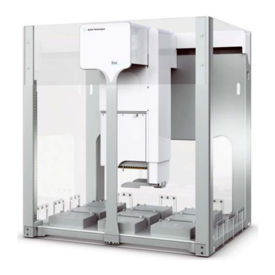
Page 16: Hardware Overview
1 Introduction Hardware overview Hardware overview About this topic This topic describes the Bravo Platform primary hardware components and the axes of motion. Primary hardware components The following figure and table describe the primary Bravo hardware components. Figure Bravo Platform components (front view) - Page 17 (x-axis). For details, see Axes of motion. You can move the head mount manually while the Bravo Platform is turned off. Tie bar The vertical bar at the front of the device that adds structural support to the Bravo head mount.
- Page 18 Bravo Platform primary axes of motion 00232 Bravo Pinch Hazard If the Bravo Platform is fitted with a gripper, the gripper moves with the Bravo head. In addition, the gripper has the following axes of motion: Bravo Platform User Guide...
- Page 19 Laboratory requirements Installation guide for your Bravo model: • G5562A, G5563A Bravo Platform Safety and Installation Guide • Bravo Automated Liquid Handling Platform Safety and Installation Guide AssayMAP Bravo Platform “AssayMAP Bravo Platform” on page 197 Bravo Platform User Guide...
-
Page 20: Connection Panel Description
Connection panel description Connection panel description Bravo rear connection panel The following figure and table describe the connection panel at the rear of the Bravo Platform. Figure Connection panel on back of Bravo Platform 00220 Bravo Back Item Feature Description... - Page 21 Connects the Bravo power cord to an AC outlet with a grounded circuit. Pump I/O port The following figure shows the Pump I/O port on the back of the Bravo Platform. The table below describes the Pump I/O port in detail. Figure...
-
Page 22: Liquid-Handling Heads
“Bravo 96AM Head overview” on page 200. The Bravo Platform can also mount a variety of pin tools for performing low-volume transfers of fixed volumes. Contact your Agilent customer representative for details. Disposable-tip heads Disposable-tip heads allow you to change pipette tips during a run to prevent cross- contamination. - Page 23 • Calibrating volumes • Controlling pipette speed • Enabling tip touching • Enabling dynamic tip extension and retraction Related information For more information about... See... Serial dilution VWorks Automation Control User Guide Bravo Platform User Guide...
-
Page 24: Software Overview
– Deck configuration – Whether the Bravo robot and an external robot can operate on the Bravo deck concurrently • Establish communication with the Bravo device using a Bravo profile. Bravo Platform User Guide... - Page 25 Figure Bravo Diagnostics dialog box Related information For more information about... See... Using Bravo Diagnostics “Using diagnostics software” on page 89 • VWorks software VWorks Automation Control Setup Guide • VWorks Automation Control User Guide Bravo Platform User Guide...
-
Page 26: Setting Up The Bravo Platform
2 Setting up the Bravo Platform This chapter contains the following topics: • “Workflow for setting up the Bravo Platform” on page 16 • “Starting up and shutting down” on page 17 • “Creating or adding a Bravo device” on page 19 •... -
Page 27: Setting Up The Bravo Platform
This topic outlines the procedures to set up the Bravo Platform. If you have an AssayMAP Bravo Platform, see “AssayMAP Bravo Platform” on page 197. Workflow The general workflow for setting up the Bravo Platform is as follows: Step Procedure See… Start up the Bravo Platform. -
Page 28: Starting Up And Shutting Down
Starting up and shutting down About this topic This topic describes how to start up and shut down the Bravo Platform when you are operating it as a standalone device. For instructions on how to turn on and turn off the Bravo Platform when it is integrated into a workstation or system, see the workstation or system user documentation. - Page 29 Turn off any accessories, for example, Pump Module. If using an Auto Filling Reservoir, disconnect the bottles to prevent siphoning. On the side of the Bravo Platform, press the power switch to the off (o) position. If applicable, uninstall the liquid-handling head.
-
Page 30: Creating Or Adding A Bravo Device
Profile to use Creating a device file If you are setting up the Bravo Platform for the first time, you will create a device file. You add the Bravo device and the external devices to the device file. To create a device file: Log in to the VWorks software as an Administrator. - Page 31 2 Setting up the Bravo Platform Creating or adding a Bravo device Adding the Bravo device to a device file Before you begin: • Ensure that any devices are physically networked to the computer. • Turn on the devices. To add devices to a device file: In the VWorks window, verify that the correct device file is open.
- Page 32 2 Setting up the Bravo Platform Creating or adding a Bravo device In the Device File tab, select the Bravo-n icon. Under Bravo Properties, type a Name for the device. By default, the software assigns Bravo-n, and increments the number for each Bravo device that you add.
- Page 33 2 Setting up the Bravo Platform Creating or adding a Bravo device Set the desired values for the following properties. Use the default values for the remaining properties. Property Description Optional. Click if you want to specify labware Allowed/prohibited restrictions for this location. The Allowed/prohibited labware labware dialog box appears.
- Page 34 2 Setting up the Bravo Platform Creating or adding a Bravo device Repeat this step for each deck location. Select File > Save. If you are creating a new device file, the Save As dialog box appears so that you can specify a name and location for your device file.
-
Page 35: Opening Bravo Diagnostics
2 Setting up the Bravo Platform Opening Bravo Diagnostics Opening Bravo Diagnostics About this topic To establish communication between the host computer and the device, you initialize the device. You can initialize the device in the following ways: • Diagnostics. To control the device using the Diagnostics software. - Page 36 2 Setting up the Bravo Platform Opening Bravo Diagnostics Figure Bravo Diagnostics dialog box Related information For information about... See... Profiles “Creating and managing profiles” on page 26 Teachpoints “Setting teachpoints” on page 34 Bravo Diagnostics “Using diagnostics software” on page 89...
-
Page 37: Creating And Managing Profiles
If you have more than one Bravo Platform of the same configuration and you may copy the profile, but you must verify that the teachpoints are correct for each of the platforms. - Page 38 2 Setting up the Bravo Platform Creating and managing profiles For information about device files, see “Creating or adding a Bravo device” on page For a detailed description of the relationships between the device file, profile, and teachpoints, see the VWorks Automation Control User Guide.
- Page 39 2 Setting up the Bravo Platform Creating and managing profiles Note: Unless you login to the VWorks software as an Administrator or Technician, only the Profile name list and the Initialize this profile button are available in the Profile Management area of the Profiles tab.
- Page 40 Jog/Teach tab will be disabled even when the device is initialized. If this check box is cleared, the Bravo Platform will run with any head installed. C AU T I O N Therefore, if the profile specifies a 96-channel head type, but a 384-channel head is installed, the head will crash.
- Page 41 To initiate communication with the Bravo Platform using the new profile, click Initialize this profile. When you initialize the Bravo Platform, the head can move. Keep clear of the Bravo WAR NING head while it is in motion. Do not touch any of the moving parts or attempt to move labware while the Bravo Platform is in operation.
-
Page 42: Initializing The Device
VWorks window. Before you start When you initialize the Bravo Platform, the head and tie bar can move. To prevent WAR NIN G potential injury, keep clear of the device while it is in motion. - Page 43 Initializing the device Verify that the selected Head type matches the installed head. For example, if the 96LT head is installed, the Bravo Platform requires a profile for the 96LT head type. Click the Configuration tab, and verify that the Location Configuration and Accessory Configuration matches the physical layout on the Bravo deck.
- Page 44 2 Setting up the Bravo Platform Initializing the device • If the tips contain fluid. Click Ignore. When the W-axis is not homed message appears, use the tools in the Jog/Teach tab in the Bravo Diagnostics dialog box to home the w-axis over a waste location. Homing the w-axis will empty the tips.
-
Page 45: Setting Teachpoints
You change the teaching tip type in the profile • You add an accessory Using a profile that is associated with teachpoints from a different Bravo Platform C AU T I O N can result in a hardware collision and cause equipment damage. Ensure that you verify the profile and associated teachpoints for each specific Bravo Platform. - Page 46 To avoid potential injury and damage to the device, only personnel trained in how to WAR NIN G teach the Bravo Platform should perform the procedures in this topic. The red Stop motors button in Bravo Diagnostics does not perform an immediate WAR NIN G stop.
- Page 47 2 Setting up the Bravo Platform Setting teachpoints Workflow for a tip box location Pressing pipette tips on the liquid-handling head requires a high degree of precision in the positioning of the head relative to the tip box, especially for 384-well tip boxes. Use the following workflow for deck locations where you plan to place either a tip box.
- Page 48 2 Setting up the Bravo Platform Setting teachpoints Make sure the disposable tip is an Agilent tip and is the same type that you specified C AU T I O N as the Teaching tip type in the profile. Click the Jog/Teach tab.
- Page 49 2 Setting up the Bravo Platform Setting teachpoints To achieve paper-thin z-axis clearance, slide a sheet of paper between the tip and the platepad. Set the z-axis increment to 0.05 mm increments. Jog the head down until the paper is barely pinched, and then jog up by 0.05 mm.
- Page 50 2 Setting up the Bravo Platform Setting teachpoints The VWorks software calculates the teachpoints for the other eight locations, keeping the z-axis coordinate the same and changing the x and y coordinates according to their spacing. Readjust the z-axis height for any positions that are taller than a standard platepad, such as the Orbital Shaking Station.
- Page 51 2 Setting up the Bravo Platform Setting teachpoints To verify the teachpoint accuracy: For disposable-tip heads, make sure you use a full set of tips to verify each C AU T I O N teachpoint. Open Bravo Diagnostics, and click the Jog/Teach tab.
-
Page 52: Verifying The Gripper Setup
Adjusting the gripper y-axis offset. You should check the gripper y-axis offset when you first set up your Bravo Platform. If necessary, you adjust the y-axis offset to ensure that the gripper fingers are centered at a platepad. This y-axis offset is saved with the given profile. - Page 53 2 Setting up the Bravo Platform Verifying the gripper setup Adjusting the gripper y-axis offset Before you adjust the gripper y-axis offset, ensure that the pipettor teachpoints (x-, y-, IMPORTANT and z-axes) have been verified for the given profile and no pipette tips or cartridges are installed on the head.
- Page 54 2 Setting up the Bravo Platform Verifying the gripper setup Visually inspect the spacing between the black rubber gripper pads and the sides of the platepad (y-axis). Make sure that all the gripper pads have clearance so that the gripper can move down without colliding with the platepad.
- Page 55 2 Setting up the Bravo Platform Verifying the gripper setup Click Back -Y or Forward +Y as required to adjust the gripper y-axis position so that the gripper pads will clear the sides of the platepad when you jog down in the next step.
- Page 56 2 Setting up the Bravo Platform Verifying the gripper setup Do not click Close gripper. Otherwise, you must redo the procedure. IMPORTANT In the Jog/Teach tab, set the y-axis increment to 0.2 mm, and then use the Back -Y and Forward +Y buttons to position the gripper so that the fingers are at equal distances around the platepad.
-
Page 57: Configuring External Robot Access
“Reporting problems” on page 87 Configuring external robot access About external robot access options For a Bravo Platform that is integrated in a system with other plate-handling robots, you can configure one of the following features: Bravo Platform User Guide... - Page 58 “Allowing concurrent operations during external robot access” on page 52 Workflow Perform the following steps to configure an external robot’s access on the Bravo deck. This workflow assumes that you have already verified the Bravo Platform teachpoints. Step For this task...
- Page 59 Ensure that you plan the external robot access locations carefully to prevent potential C AU T I O N hardware collisions. A collision between an external robot and the Bravo Platform can damage the Bravo Platform, the external robot, or both robots.
- Page 60 2 Setting up the Bravo Platform Configuring external robot access Physical factors Description External robot Landscape and portrait gripper orientations require different space allocations on the orientation for Bravo deck. Some robots can grip using either orientation. gripping labware: •...
- Page 61 2 Setting up the Bravo Platform Configuring external robot access Software scheduling conflicts The software resolves conflicts, where both the Bravo robot and external robot are scheduled to approach a blocked location, as follows: • If the Bravo robot is at a blocked location when an external robot is scheduled to approach, the Bravo robot will complete the task in progress before moving to a different location.
- Page 62 2 Setting up the Bravo Platform Configuring external robot access • Direct Drive Robot with a portrait grip. Approaches location 3 at the right side of the Bravo deck. To be conservative, location 6 is also reserved for this robot and blocked for access by the Bravo robot.
- Page 63 2 Setting up the Bravo Platform Configuring external robot access In the Move Bravo to this safe location box, select the deck location number where the Bravo head should move for the duration while the external robot is accessing the Bravo deck.
- Page 64 2 Setting up the Bravo Platform Configuring external robot access In the deck image, highlights appear at additional deck locations to be blocked. The Bravo robot cannot access blocked locations while the external robot is accessing the target location. The software proposes the most conservative layout for avoiding potential collisions.
- Page 65 2 Setting up the Bravo Platform Configuring external robot access Related information For information about... See... Profiles “Creating and managing profiles” on page 26 Editing teachpoints “Setting teachpoints” on page 34 Opening diagnostics “Opening Bravo Diagnostics” on page 24 Bravo Platform User Guide...
-
Page 66: Preparing For A Protocol Run
3 Preparing for a protocol run Before you start a protocol run, you should check the Bravo Platform teachpoints and the protocol to ensure optimum operation. This chapter contains the following topics: • “Workflow for preparing a protocol run” on page 56 •... -
Page 67: Workflow For Preparing A Protocol Run
The workflow for preparing a protocol run is as follows: Step For this task... See... • Review how to operate safely and G5562A, G5563A Bravo Platform how to stop in an emergency. Safety and Installation Guide • “Emergency stops” on page 56 Plan for the protocol run. -
Page 68: Planning For The Protocol Run
Before you start a run, make sure you review the protocol and determine the following: • The correct liquid-handling head is installed. To avoid variability problems, use only Agilent Technologies brand tips. • The accessories and labware required for the protocol are where they should be positioned. -
Page 69: About Performing Mock Runs
Related information For information about... See... Stopping the device in an emergency “Emergency stops” on page 56 Writing protocols VWorks Automation Control User Guide Preparing for a run “Workflow for preparing a protocol run” on page 56 Bravo Platform User Guide... -
Page 70: Maintenance And Troubleshooting
Maintenance and troubleshooting This chapter tells you how to keep your Bravo Platform in good working order through cleaning, inspection, and maintenance. It also explains what to do when you encounter a problem. This chapter contains the following topics: •... -
Page 71: Routine Maintenance And Cleaning
Use a clean soft cloth to clean up spills on any part of the device immediately after a protocol run. Clean the Bravo Platform weekly or as needed. Use standard laboratory wipes and a mild detergent or isopropyl alcohol to clean the exterior painted white surfaces and the metal surfaces of dust, grime, chemical deposits, and other debris. - Page 72 Station. Related information For information about... See... Cleaning between protocol runs “Cleaning up after a run” on page 62 Cleaning the Bravo Platform “Routine maintenance and cleaning” on page 60 Setting teachpoints “Setting teachpoints” on page 34 Reporting a problem “Reporting problems”...
-
Page 73: Cleaning Up After A Run
Bravo Platform to the cap connector. Empty the waste container, replace the cap, and attach the fluid line that pumps away from the Bravo Platform to the cap connector. To prime the fluid lines between the pump and reservoirs, use Diagnostics to fill the lines with the appropriate fluid. -
Page 74: Changing The Bravo Head
Uninstalling the liquid-handling head To uninstall the liquid-handling head: Ensure that the Bravo Platform is turned off. Check that the power switch located on the right side is set to off (o) and the status lights on the device front are not lit. - Page 75 ) retainer pin and ( ) head lock Reaching from the left side of the Bravo tie bar, grasp the head firmly as the following figure shows: With your left hand firmly grip the left side of the head. Bravo Platform User Guide...
- Page 76 Carefully place the stand (1) onto the head, guiding the side cutouts onto the two side tabs (2) on the head. Use care to avoid touching the probes. Bravo Platform User Guide...
- Page 77 Installing the liquid-handling head To install a Bravo liquid-handling head: Make sure that the Bravo Platform is turned off and that the Bravo head mount is in its home position, which is centered above deck location 5. Note: If the device it off, you can use your hands to move the head mount gently into position.
- Page 78 Using both hands, carefully lift the stand off of the head while guiding the stand’s side cutouts (1) off the head side tabs (2). Use care to avoid touching the probes. Bravo Platform User Guide...
- Page 79 While supporting the head with your hands, slide the head onto the Bravo head mount. Press the head firmly into place to ensure the head is plugged into the connector receptacle on the head mount. You should hear the click when the retaining pins snap into place. Bravo Platform User Guide...
- Page 80 ) retainer pin and ( ) head lock To lock the head, rotate the head lock clockwise until it reaches its hard stop. This ensures that the head is fully seated and does not shift position during operation. Bravo Platform User Guide...
- Page 81 IMPORTANT profile for the new Bravo head. On the side of the Bravo Platform, press the power switch to the on (I) position. To initialize the Bravo Platform, click Initialize selected devices in the device file. Bravo Platform User Guide...
- Page 82 Changing the Bravo head Open Diagnostics, and in the Jog/Teach tab, make sure that a value is displayed for each axis. This confirms communication between the Bravo Platform and VWorks software. If you opened an existing device file in step...
-
Page 83: Testing The Safety Equipment
Testing the safety equipment Testing the safety equipment The Bravo interlock circuit must be closed for the Bravo Platform to operate. The Light Curtain and the pendant are connected to the Bravo interlock circuit. Use the following procedure to verify that the Bravo motion stops abruptly when you press the emergency-stop button on the pendant or interrupt the Light Curtain. -
Page 84: Replacing The Fuse
A blown fuse can indicate more serious problems. If the new fuse blows after C AU T I O N replacement, contact Agilent Automation Solutions Technical Support. Using an incorrect fuse can damage the Bravo Platform. Ensure that you have the C AU T I O N correct fuse for the device. - Page 85 Replacing the fuse Procedure To replace the fuse in the power switch: Shut down the Bravo Platform, and unplug the power cable from the rear panel connector. At the rear panel power switch enclosure, use a small flat-head screwdriver (2.5 mm) to pry open the tab on the fuse enclosure and open the enclosure cover.
-
Page 86: Retracting Tip Box Stripper Pins
“Hardware overview” on page 5 • Safety guidelines Automation Solutions Products General Safety Guide • Safety and installation guide for your model Bravo Platform, for example, G5562A, G5563A Bravo Platform Safety and Installation Guide How to report a problem “Reporting problems” on page 87... - Page 87 Place the pipette head upside down on a stable surface, so that the barrels are facing up and the front of the pipette head is facing you as the following figure shows. If directional arrows appear on the pins, gently rotate the pins so that the arrows are facing you. Bravo Platform User Guide...
-
Page 88: Manually Moving The Head Or Gripper
This topic describes how to disable the axis servo motors, so that you can move the head manually. For example, you might want to move the head position when changing liquid-handling heads or cleaning the Bravo Platform. Moving the Bravo head or gripper in any of its axes without first disabling the C AU T I O N servo motors can damage the device. - Page 89 IMPORTANT While ensuring that one hand is free to support the labware held by the gripper, use a 2.5-mm flat-blade screwdriver to turn the G-axis lead screw counterclockwise to open the gripper and release the labware. Bravo Platform User Guide...
-
Page 90: Recovering From A Head Collision
This topic describes what to do after a head collision has occurred. Before you start Before you start the inspection of the Bravo Platform, clean up any spills that might have occurred as a result of the collision. Procedure To inspect the Bravo Platform: Inspect the impacted parts for visible signs of damage. - Page 91 If new noises are present or if any axis movement is impaired, contact Agilent Automation Solutions Technical Support. Make sure the Bravo Platform alignment was not compromised: If the liquid-handling head was impacted side-to-side, re-install the head. Attach the correct pipette tip type.
-
Page 92: Troubleshooting Hardware Problems
About this topic This topic lists some potential hardware problems that you might encounter when using the Bravo Platform. If you encounter a problem, locate the problem under one of the following categories, and try the recommended solution to resolve the problem. - Page 93 The location requires a gripper “Setting teachpoints” on page teachpoint adjustment. The head or gripper movement is The Bravo Platform might require Contact Agilent Automation rough or strained, or rubbing or service. Solutions Technical Support. scraping noises are audible during moves.
- Page 94 Technical Support. an O-ring replacement. Liquid fails to pump into or drain The Pump Module tubing has Inspect the tubing and the from an autofilling reservoir. deteriorated or is not connected connections, and replace, if properly. necessary. Bravo Platform User Guide...
- Page 95 Weigh Station. flooding. Related information For information about... See... Laboratory requirements and safety G5562A, G5563A Bravo Platform Safety guidelines and Installation Guide Stopping in an emergency “Emergency stops” on page 56 Reporting a problem “Reporting problems” on page 87...
-
Page 96: Troubleshooting Hardware-Related Error Messages
4 Maintenance and troubleshooting Troubleshooting hardware-related error messages Troubleshooting hardware-related error messages About this topic This topic describes the most common error messages that might be encountered with the Bravo Platform and provides some possible solutions. Troubleshooting table Error message/problem Cause Recommended actions... - Page 97 “Starting up and shutting down” on page 17 Preparing the Bravo for a run “Workflow for preparing a protocol run” on page 56 Hardware components “Hardware overview” on page 5 Connecting Ethernet cables G5562A, G5563A Bravo Platform Safety and Installation Guide Bravo Platform User Guide...
-
Page 98: Reporting Problems
Contacting technical support If you find a problem with the Bravo Platform, contact Agilent Automation Solutions Technical Support. For contact information, go to https://www.agilent.com/en-us/ contact-us/page. - Page 99 81 • “Troubleshooting hardware-related error messages” on page 85 Software error messages VWorks Automation Control User Guide Stopping in an emergency “Emergency stops” on page 56 Shutting down “Starting up and shutting down” on page 17 Bravo Platform User Guide...
-
Page 100: Using Diagnostics Software
This chapter explains how to use the Diagnostics software to control the Bravo Platform. Only administrators and experienced personnel should use the procedures in this chapter to diagnose errors with the Bravo Platform. This chapter contains the following topics: •... -
Page 101: Homing The Liquid-Handling Head
The liquid-handling head has a defined home position for each axis of motion. Homing sends the head to the home position for the axes. Home the liquid-handling head to reset the axes. For example, if you notice the Bravo Platform is not moving to locations or teachpoints accurately, home the head. - Page 102 For information about... See... Opening Diagnostics “Opening Bravo Diagnostics” on page 24 Moving the liquid-handling head “Manually moving the head or gripper” manually on page 77 Changing the liquid-handling head “Changing the Bravo head” on page 63 Bravo Platform User Guide...
-
Page 103: Jogging The Liquid-Handling Head
To avoid potential injury and damage to the device, only personnel trained in how to WAR NING teach the Bravo Platform should use the Jog/Teach tab controls. To perform an emergency stop, press the red button on the emergency-stop pendant. - Page 104 Bravo Pinch Hazard Jogging the liquid-handling head Keep away from the Bravo Platform when the liquid-handling head is moving or WAR NIN G about to move, especially in the z-axis direction. The head’s z-axis motor is particularly powerful. It might not stop immediately in a collision and a pipette tip could pierce your hand.
- Page 105 “Jog/Teach tab quick reference” on page 232 Moving the liquid-handling head “Manually moving the head or gripper” on manually page 77 Setting up the Bravo Platform “Workflow for setting up the Bravo Platform” on page 16 Bravo Platform User Guide...
-
Page 106: Using The Move And Approach Commands
To avoid potential injury and damage to the device, only personnel trained in how to WAR NIN G teach the Bravo Platform should use the Jog/Teach tab controls. The red Stop motors button in Bravo Diagnostics does not perform an immediate WAR NIN G stop. -
Page 107: Using The Gripper Controls
Platform” on page 16 Using the gripper controls About this topic If your Bravo Platform has a gripper, you can use the controls in Diagnostics to move the gripper and troubleshoot problems. “Verifying the gripper setup” on page 41 for instructions on how to: •... - Page 108 To jog the gripper: In the Jog Gripper Axes area, specify the distance (mm) to jog. Click the direction button to move the gripper. In the Zg-Axis and G-Axis areas, check the new distance from the home position. Bravo Platform User Guide...
- Page 109 Homing the gripper is done automatically during startup. However, you might want to home the gripper during troubleshooting processes. To home the gripper: In the Zg-Axis or G-Axis areas, click Home Zg or Home G. The gripper moves to the predefined position on the corresponding axis. Bravo Platform User Guide...
- Page 110 90 • “Jogging the liquid-handling head” on page 92 Moving the liquid-handling head “Manually moving the head or gripper” on manually page 77 Opening Diagnostics “Opening Bravo Diagnostics” on page 24 Bravo Platform User Guide...
-
Page 111: Performing A Task Using Bravo Diagnostics
Initialize the profile in Bravo Diagnostics, and then click the Processes tab. • Verify that the correct labware is positioned on the Bravo deck. Procedure Performing a task requires that you: • Choose a location • Select a task and task parameters Bravo Platform User Guide... - Page 112 Click a representative well in the plate graphic to select the corresponding quadrant of wells. The selection message appears below the plate graphic. In the Command Parameters area: Select the process from the Command to execute list. Set the parameter values for the command. Bravo Platform User Guide...
- Page 113 Alternatively, you may click the emergency-stop button on the pendant to stop the diagnostic process. Related information For information about... See... Bravo task parameters “Processes tab quick reference” on page 243 Setting up the Bravo Platform “Workflow for setting up the Bravo Platform” on page 16 Bravo Platform User Guide...
-
Page 114: Accessories And Platepads
“Installing and configuring the Peltier Thermal Station” on page 166 • “(Bravo SRT only) Setting up an LT tip box location” on page 172 For details on how to set up accessories on the AssayMAP Bravo Platform, see the AssayMAP Bravo Platform Installation Guide. -
Page 115: Bravo Accessories Overview
A Accessories and platepads Bravo accessories overview Bravo accessories overview Description You can add accessories to the Bravo Platform to enhance existing functions and facilitate operation. The accessories and platepads include: Accessory Description See… Alignment Station Positions 1536-well microplates for “Installing and... - Page 116 For information about… See… Pipette heads “Liquid-handling heads” on page 11 AssayMAP Bravo Platform “AssayMAP Bravo Platform” on page 197 Setting up liquid and labware VWorks Automation Control Setup Guide definitions Using an accessory in a protocol VWorks Automation Control User Guide...
-
Page 117: Installing And Setting Up An Orbital Shaking Station
Station” on page 111 Edit the teachpoint using the pipettor “Adjusting the teachpoint using teach plate. Be sure to consider the 10- a teach plate” on page 113 mm thickness of the teach plate when you edit the teachpoint. Bravo Platform User Guide... - Page 118 If the Orbital Shaking Station does not have its own control module, make sure that you have an Inheco Single TEC controller (STC) or Multi TEC controller (MTC). To prevent a potential injury, turn off the Bravo Platform before you install or remove WAR NIN G the accessory.
- Page 119 To connect an Orbital Shaking Station that has its own control module: Route the Orbital Shaking Station cable off the deck and connect it to the control module that contains the power plug. See following figure, item 1. Bravo Platform User Guide...
- Page 120 At the first station, connect the serial cable from the speed control (on the power cord) to the RS-232 port on the speed control of the second station. Repeat this step for each station in the series. Figure Connecting multiple Orbital Shaking Stations Bravo Platform User Guide...
- Page 121 Note: The Serial Port parameter is automatically defined when a USB-to- serial adapter is connected to the computer. You might need to look up the port number assigned to this device in the Microsoft Windows Device Manager. Bravo Platform User Guide...
- Page 122 Ensure that the profile is initialized in Bravo Diagnostics before you perform the following procedure. To test the Orbital Shaking Station: In the Accessory Configuration area, click the Orbital Shaking Station icon, and then click Diagnose accessory. The Bravo Accessory Diagnostics dialog box opens. Bravo Platform User Guide...
- Page 123 In the Bravo Accessory Diagnostics dialog box, click Stop, and then click OK. Related information For information about… See… Bravo Platform hardware components “Hardware overview” on page 5 Adjusting the teachpoint “Using the teach plate to set the teachpoint for an accessory” on page 113...
-
Page 124: Using The Teach Plate To Set The Teachpoint For An Accessory
In the Profiles tab, click Update this profile. Related information For information about… See… Hardware components “Hardware overview” on page 5 Editing teachpoints “Setting teachpoints” on page 34 Using the accessory in a protocol VWorks Automation Control User Guide Bravo Platform User Guide... -
Page 125: Installing And Setting Up A Vacuum Filtration Station
Installing and setting up a Vacuum Filtration Station Installing and setting up a Vacuum Filtration Station About this topic This topic describes how to set up the Vacuum Filtration Station on the Bravo Platform. This topic contains the following information: •... -
Page 126: Component Descriptions And Options
The Vacuum Filtration Station applies vacuum to filter the contents of microplates placed on the station. The station consists of a collar and a manifold base that can be assembled and disassembled automatically. The following figure shows the primary components. Bravo Platform User Guide... - Page 127 Note: Different types of gasket frame inserts are available. See the manufacturer’s user documentation for a detailed description. Bravo Platform User Guide...
-
Page 128: Supported Stacking Configurations
• Configuration B. The filter plate is not part of the station assembly. The robot will move the filter plate to the station during the protocol run after the assembly process is finished. Bravo Platform User Guide... -
Page 129: Installing The Station
– Agilent ME4C NT VARIO Pump For detailed information, see the ME4C NT VARIO Pump manual at https:// www.vacuubrand.com. • Available serial port on the controlling computer Bravo Platform User Guide... - Page 130 Ensure that the base sits level and that the vacuum port faces in the correct orientation for the tubing exit. To secure the base, use a M1.5 hex wrench to tighten the setscrew in the platepad tab. Bravo Platform User Guide...
-
Page 131: Connecting To House Vacuum With The Pinch-Valve Module
(3) to the quick-disconnect fitting on the short arm of the four-way connector. Connect the coupling insert on the end of the vacuum pressure gauge tubing (4) to the quick-disconnect fitting on the long arm of the four-way connector. Bravo Platform User Guide... - Page 132 Helps regulate the vacuum pressure to prevent the valve-and-gauge pinch-valve module tubing from collapsing. assembly Pinch-valve module assembly • 3-way Branches the tubing from the Vacuum Filtration Station connector base to the vent and valve ports on the pinch-valve module. Bravo Platform User Guide...
- Page 133 Connect the tubing between the in-line filter and the vacuum source (5). Connect the power cable (6) from the pinch-valve module to an AC outlet. Connect the communications cable (7) from the pinch-valve module to a com port on the controlling computer. Bravo Platform User Guide...
- Page 134 You may need to massage the tubing slightly to open it up again. Now you are ready to configure the Vacuum Filtration Station in the software. See “Configuring the Vacuum Filtration Station in Bravo Diagnostics” on page 128. Bravo Platform User Guide...
-
Page 135: Connecting And Configuring The Agilent Vario Vacuum Pump
The following figure shows the connections for a Vacuum Filtration Station that uses the ME4C NT VARIO Vacuum Pump. Figure Vacuum Filtration Station connections for ME4C NT VARIO Vacuum Pump Item Name Description Vacuum Contains a vacuum port on that base that connects to Filtration Station the tubing. Bravo Platform User Guide... - Page 136 Connect the power cord (9) from the pump to an AC outlet. Configure the controller communication settings as described in the following procedure. Turn on the controlling computer. At the back of the pump, press the power switch to the on (|) position. Bravo Platform User Guide...
- Page 137 Use the selection knob to move the selection to Back, and press the knob to exit each display until you exit the Configuration display. Ensure that the controller displays Vac control. Bravo Platform User Guide...
-
Page 138: Uninstalling The Vacuum Filtration Station
If applicable, disconnect the pinch-valve module from the vacuum source. Disconnect the tube from the Vacuum Filtration Station. Remove the set screw that is holding the station base to the platepad. Remove the Vacuum Filtration Station from the platepad. Bravo Platform User Guide... -
Page 139: Configuring The Vacuum Filtration Station In Bravo Diagnostics
Select this option if the station is connected to the ME4C NT VARIO Vacuum Pump. If you select ME4CVario, set the Pump Pressure Units to match the unit setting on the VARIO pump controller. The options are mbar, Torr, and hPa. Click Next. Bravo Platform User Guide... - Page 140 Click Finish. Note: If you verified the accuracy of the platepad teachpoint before installing and configuring the Vacuum Filtration Station, no further adjustment to the teachpoint should be required. In the Profiles tab, click Update this profile. Bravo Platform User Guide...
-
Page 141: Testing The Vacuum Filtration Station
In the Accessory Diagnostics dialog box, start the vacuum as follows: Set the Vent valve to Closed. Set the Vacuum valve to Open. Click Execute. Figure Accessory Diagnostics dialog box for the Standard connection To stop the vacuum: Bravo Platform User Guide... - Page 142 Verify that the pre-assembled Vacuum Filtration Station is in place on the target deck location and connected to the VARIO Vacuum Pump. In Diagnostics, click the Configuration tab. In the Accessory Configuration area, highlight Vacuum Filtration Station, and then click Diagnose accessory. The Accessory Diagnostics dialog box opens. Bravo Platform User Guide...
- Page 143 To start the vacuum: Set the Vent valve to Close. Set the Pump to On. Set the Target pressure. Click Execute. To stop the vacuum: Set the Vent valve to Open. Set the Pump to Off. Click Execute. Bravo Platform User Guide...
- Page 144 Vacuum Filtration Station, including specifying the gripper offset The protocol liquid-handling tasks for VWorks Automation Control User Guide the Vacuum Filtration Station Videos that show the Bravo Platform, http://www.agilent.com/en-us/products/ Vacuum Filtration Station, and VWorks automation-solutions/automated-liquid- software handling/bravo-automated-liquid- handling-platform http://www.agilent.com/en-us/products/...
-
Page 145: Setting Up A Trash Or Filter Plate Holder Accessory
The accessory can be installed at Bravo deck locations 4 and 6, which have cutouts for through-deck access. Figure Bravo Platform on deck risers and top view of deck location cutouts The hardware setup requirements vary depending on how the accessory is to be used. •... - Page 146 Filter Plate Holder. If the accessory is used as a location for placing labware, the Bravo Platform does not require deck risers. The cutout in the center of the accessory is sufficient to provide the extra space for the filter plate wells to protrude beyond the bottom edges of the filter plate skirt.
- Page 147 • Click Yes if you plan to reteach this location. The image of the accessory appears at the specified deck location in the Configuration tab, as the following figure shows. Bravo Platform User Guide...
- Page 148 “labware” at the corresponding deck location. In the Bravo Subprocess, use the Tips Off task to eject the pipette tips at the Tip Trash Bin accessory. The following figure shows an example protocol. For more details, see the VWorks Automation Control User Guide. Bravo Platform User Guide...
- Page 149 Figure Example of VWorks protocol with static labware configuration for tip trash at deck location 6 Related information For information about... See... Editing teachpoints “Setting teachpoints” on page 34 Using an accessory in a protocol VWorks Automation Control User Guide Bravo Platform User Guide...
-
Page 150: Configuring A Platepad For Delidding
In the Profiles tab, click Update this profile. Related information For information about... See... Opening Diagnostics “Opening Bravo Diagnostics” on page 24 Editing teachpoints “Setting teachpoints” on page 34 Using an accessory in a protocol VWorks Automation Control User Guide Bravo Platform User Guide... -
Page 151: Installing And Configuring A Platepad Or Alignment Station
The Alignment Station can accommodate 1536-well microplates, small-transfer (ST) tip boxes, and any other microplate requiring precision location. Before you start Make sure you have the following: • Alignment Station or platepad • M5 hex wrench • 1.5-mm hex wrench Bravo Platform User Guide... - Page 152 Figure Crosshairs orientation on the Bravo deck (top view) Installing a platepad or Alignment Station Turn off the Bravo Platform before you install or remove the accessory. C AU T I O N To install a platepad or Alignment Station:...
- Page 153 Standard Platepad. Verify the teachpoint for this location. For instructions, see “Setting teachpoints” on page Related information For information about... See... Bravo Platform hardware components “Hardware overview” on page 5 Editing teachpoints “Setting teachpoints” on page 34 Bravo Platform User Guide...
-
Page 154: Installing And Configuring A Magnetic Bead Accessory
Magnetic Bead Accessory To avoid potential injury and damage to the device, only personnel trained in how to WAR NIN G set up Magnetic Bead Accessory and teach the Bravo Platform should perform the following procedures. Before you start Make sure you have the following: •... - Page 155 When a message appears and asks whether to move the teachpoint to a safe Z height, click No. The image of the accessory appears at the specified deck location in the Configuration tab. In the Profiles tab, click Update this profile. Bravo Platform User Guide...
- Page 156 (1). Ensure that the accessory is fully seated on the platepad. Figure Magnetic Bead accessory on top of a standard platepad Using the 1.5 mm wrench, tighten the set screw in the tab, as shown in preceding figure (2), to secure the base to the platepad. Bravo Platform User Guide...
- Page 157 Verify the this accessory teachpoint for your microplate type using a full set of tips. For IMPORTANT guidance, contact Agilent Automation Solutions Technical Support. Related information For information about... See... Bravo Platform hardware components “Hardware overview” on page 5 Editing teachpoints “Setting teachpoints” on page 34 Bravo Platform User Guide...
-
Page 158: Installing And Setting Up A Nested Rack Insert
You should install the Nested Rack Insert if you are using nestable tip racks on the Bravo Platform. The insert ensures the stability of a nestable tip rack during tips-on and tips-off tasks. Up to five nestable tip racks can be stacked on a single platepad using the Nested Rack Insert. - Page 159 When the configuration message appears, click Yes to initialize the accessory and move the teachpoint to a safe height. Set the teachpoint for the Nested Rack Insert using the same procedure that you would for a platepad. Bravo Platform User Guide...
- Page 160 In the Profiles tab, click Update this profile. To verify the setup, perform a tips-on task. Related information For information about... See... Bravo Platform hardware components “Hardware overview” on page 5 Gripper y-axis offset “Verifying the gripper setup” on page 41 Editing teachpoints “Setting teachpoints”...
-
Page 161: Using The Manual Fill Reservoir
To empty the reservoir, lift it from the deck location and discard the fluid according to applicable regulations. Related information For information about… See… Safety guidelines G5562A, G5563A Bravo Platform Safety and Installation Guide Setting up liquid and labware VWorks Automation Control Setup Guide definitions Using the accessory in a protocol... -
Page 162: Setting Up The Thermal Station (Cooling Pad)
Routing the Thermal Station tubing out the front of the Bravo deck will interfere with WAR NIN G the Bravo Light Curtain. Operating the Bravo Platform without the Light Curtain can expose operators to moving-parts hazards. To prevent potential injury, ensure that no tubing or other accessory parts interfere with the operation of the Bravo Light Curtain. - Page 163 Hex wrenches: M1.5, M2, and M5 • Plumber’s tape • Liquid chilling unit, tubing, and manufacturer user documentation To prevent a potential injury, turn off the Bravo Platform before you install or remove WAR NING the accessory. Procedure To install the Thermal Station: Ensure that the platepad is removed from the target deck location.
- Page 164 Place the thermal pad on top of the adapter pad. Make sure the thermal pad is level and fully seated on the adapter pad. Using an M1.5 hex wrench, tighten the setscrews on the adapter pad tabs as follows: Bravo Platform User Guide...
- Page 165 Watch for the Liquid Level Low message to display on the front panel. Turn off the unit and fill it with 25% EtOH or cooling fluid recommended by manufacturer. Repeat steps a to c. The unit should hold 600 to 700 mL. Bravo Platform User Guide...
- Page 166 Verifying and setting the teachpoint for “Using the teach plate to set the the accessory teachpoint for an accessory” on page 113 • “Setting teachpoints” on page 34 Using the accessory in a protocol VWorks Automation Control User Guide Bravo Platform User Guide...
-
Page 167: Installing A Heating Shaking Station
Heating Shaking Station uses a short adapter pad to attach to the Bravo deck. The station uses the Inheco Single TEC Control (STC) or Multi TEC Control (MTC) to connect to the computer and power source. Figure Heating Shaking Station and adapter pad Figure STC and MTC Controllers Bravo Platform User Guide... - Page 168 A Accessories and platepads Installing a Heating Shaking Station Before you start To prevent potential injury and damage to the device, turn off the Bravo Platform WAR NIN G before you install or remove an accessory. The Heating Shaking Station may be installed at any deck location using the short adapter pad instead of a platepad.
- Page 169 Connect the STC or MTC Controller power and communication cables. See the Inheco user documentation for details on how to connect the STC or MTC. Press the STC or MTC Controller power switch to the on (|) position. Bravo Platform User Guide...
-
Page 170: Setting Up Thermal And Shaking Stations (Inheco Controller)
Teleshake 95 The STC can control a single Inheco device, and the MTC can control multiple Inheco devices. For a detailed description of the Inheco STC or MTC, see the Inheco STC or MTC user documentation. Bravo Platform User Guide... - Page 171 When the configuration message appears, click Yes to initialize the accessory and move the teachpoint to a safe height. In the Profiles tab, click Update this profile. Edit the location’s teachpoint for the accessory. See “Teaching a thermal or thermal shaking station” on page 162. Bravo Platform User Guide...
- Page 172 Note: The software obtains the device name from the STC or MTC, and then the Inheco name of the device appears in the display of the dialog box, for example, CPAC Ultraflat or Teleshake 95. Shaking accessories only. Set the parameters in the Shake area: Bravo Platform User Guide...
- Page 173 The teaching procedure can vary depending on the combination of microplate, plate nest, and adapter. The procedures in this section are for the following configurations on a Bravo Platform with a disposable-tip head: • Peltier Thermal Station with generic plate nest and adapter •...
- Page 174 Automation Solutions Technical Support for guidance on whether your microplate requires a custom plate nest and adapter. Use the following procedure only on a Bravo Platform with a disposable-tip head. C AU T I O N To set the teachpoint for a generic Peltier Thermal Station or Heating Shaking Station: Place the microplate securely in the plate nest of the thermal station.
- Page 175 Make sure that the gripper holds the microplate securely and keeps it level while moving the microplate from location to location. Ensure that the gripper places, but does not drop the microplate at the destination location. Bravo Platform User Guide...
- Page 176 See… Heating Shaking Station “Installing a Heating Shaking Station” on page 156 Peltier Thermal Station “Installing and configuring the Peltier Thermal Station” on page 166 Using the accessory in a protocol VWorks Automation Control User Guide Bravo Platform User Guide...
-
Page 177: Installing And Configuring The Peltier Thermal Station
Ensure that you have the correct plate nest and adapter for the requirements of your IMPORTANT assay. Your microplate must nest in the station correctly to ensure efficient heat transfer. For more information, contact Agilent Automation Solutions Technical Support. Bravo Platform User Guide... - Page 178 Ensure you have the following: • Bravo Platform with risers installed The Peltier Thermal Station is too tall to sit at deck level and must be installed in a deck cutout at deck location 4 or 6, as the following figure shows.
- Page 179 Figure Plastic interface on the top of the Peltier Thermal Station Refer to the following figure, and then place the Peltier Thermal Station assembly into the cutout hole as follows: Bravo Platform User Guide...
- Page 180 Tapping the Peltier Thermal Station bracket in place Ensure that the Peltier Thermal Station sits flush in the cutout and that the bracket is seated on the Bravo deck. Install the four M3 bolts that secure the bracket to the deck. Bravo Platform User Guide...
- Page 181 Install the M3 screw in the center of the plate nest to secure it to the Peltier Thermal Station. Figure Installing the custom plate nest Connect the cables: Connect the cable from the Peltier Thermal Station to the Inheco STC or MTC Controller. Bravo Platform User Guide...
- Page 182 See… Configuring the Peltier Thermal Station “Setting up thermal and shaking stations in the Bravo profile and setting the (Inheco controller)” on page 159 teachpoint Using the accessory in a protocol VWorks Automation Control User Guide Bravo Platform User Guide...
-
Page 183: (Bravo Srt Only) Setting Up An Lt Tip Box Location
Ensure that you have the following: • M5 hex wrench for removing a standard SRT platepad • SRT platepad for 250-µL tip box • Star-head screw and wrench for installing the SRT 250-µL tip box platepad Bravo Platform User Guide... - Page 184 In Bravo Diagnostics, click the Profiles tab, and open the profile for the given Bravo SRT platform. In the Profiles tab, select the This is a Bravo SRT check box. In the Configuration tab, select the Location. Bravo Platform User Guide...
- Page 185 In the Profiles tab, click Update this profile. Related information For information about... See... Starting Diagnostics “Opening Bravo Diagnostics” on page 24 Editing teachpoints “Setting teachpoints” on page 34 Bravo Platform User Guide...
-
Page 186: Autofilling Accessories
“Configuring an autofilling station for the Bravo Platform” on page 177 • “Setting up a Weigh Station” on page 182 For details on how to set up accessories on the AssayMAP Bravo Platform, see the AssayMAP Bravo Platform Installation Guide. -
Page 187: Autofilling Station Overview And Setup Workflow
Autofilling station overview and setup workflow About this topic An autofilling station is a location on the Bravo Platform where a reservoir can be automatically filled with liquid. This topic describes the components and provides the workflow for setting up an autofilling station. -
Page 188: Configuring An Autofilling Station For The Bravo Platform
Connect the Pump Module, Weigh Station, and an Agilent autofilling type reservoir. For details on how to install a basic autofilling station, see the Pump Module User Guide. If you are installing an autofilling station on an AssayMAP Bravo Platform, see the IMPORTANT AssayMAP Bravo Platform Installation Guide. - Page 189 Next. For example, if only one Pump Module is connected to this Bravo Platform, select 1. If two Pump Modules are connected to this Bravo Platform, select 2, and so forth. Note: To make a change, click the number to display a list of options.
- Page 190 B Autofilling accessories Configuring an autofilling station for the Bravo Platform Parameter Settings Empty module Specify the Pump Module that this deck location uses. For example, select 1 if only one Pump Module is connected to this device. One Pump Module can function as both the Fill module and Empty module.
- Page 191 B Autofilling accessories Configuring an autofilling station for the Bravo Platform In the Accessory Diagnostics dialog box, verify the following settings. Control Description Pump on time (s) Specifies the duration that the selected pump on the Pump Module runs when you click Run pumps.
- Page 192 B Autofilling accessories Configuring an autofilling station for the Bravo Platform Control Description Fill pump Specifies which of the two pumps on the Pump Module to use for filling the container, where 1 controls the upper pump. 2 controls the lower pump.
-
Page 193: Setting Up A Weigh Station
Guide. • Verify that the Autofill Station accessory is configured in Bravo Diagnostics. See “Configuring an autofilling station for the Bravo Platform” on page 177. Procedure Before the Weigh Station is ready for use in a protocol, you must calibrate the empty and full settings. - Page 194 Setting up a Weigh Station In the Accessory Diagnostics dialog box, click the second tab. At the Bravo Platform, place the reservoir on the Weigh Station. Make sure the reservoir is empty. In the Accessory Diagnostics dialog box, click Set Tare to configure the empty setting.
- Page 195 Pump Module User Guide Configuring the autofilling “Configuring an autofilling station for the Bravo function Platform” on page 177 Editing teachpoints “Setting teachpoints” on page 34 Using an accessory in a protocol VWorks Automation Control User Guide Bravo Platform User Guide...
-
Page 196: Reader
C Setting up the Barcode Reader This section contains the following topics: • “About setting up the Barcode Reader” on page 186 • “Installing or removing the Barcode Reader” on page 188 • “Creating a profile for the Barcode Reader” on page 189 •... -
Page 197: About Setting Up The Barcode Reader
“Creating a profile for the Barcode and create a profile for the Reader” on page 189 Barcode Reader. Specify the Barcode Reader “Specifying the Barcode Reader location” location in the Bravo device file. on page 191 Bravo Platform User Guide... - Page 198 Related information For information about... See... • Setting up other accessories “Accessories and platepads” on page 103 • “Autofilling accessories” on page 175 Using an accessory in a protocol VWorks Automation Control User Guide Bravo Platform User Guide...
-
Page 199: Installing Or Removing The Barcode Reader
• M4 hex wrench Installing the Barcode Reader Turn off the Bravo Platform before you install or remove the accessory. WAR NING To install the Barcode Reader: If a platepad is already installed at the target installation location, uninstall the platepad. -
Page 200: Creating A Profile For The Barcode Reader
In the Available Devices area, double-click the Microscan Barcode Reader. The Microscan Barcode Reader icon appears in the Devices area. In the Devices area, select the Microscan Barcode Reader icon, and click Device diagnostics. The Barcode Reader Diagnostics dialog box opens. Bravo Platform User Guide... - Page 201 Installing the Barcode Reader “Installing or removing the Barcode Reader” on page 188 Specifying the Barcode Reader location “Specifying the Barcode Reader location” on the Bravo Platform on page 191 Making adjustments and “Testing and optimizing barcode troubleshooting the Barcode Reader scanning”...
-
Page 202: Specifying The Barcode Reader Location
In the location properties table, select the Barcode Reader for one of the following: • BCR on west side • BCR on east side Note: The Bravo Barcode Reader can scan barcode labels on the labware east and west sides only. Bravo Platform User Guide... -
Page 203: Testing And Optimizing Barcode Scanning
“Autofilling accessories” on page 175 Testing and optimizing barcode scanning About this topic This topics describes: • “Using diagnostics to test the barcode scanning (Microscan sensor)” on page 193 • “Adjusting the scan angle” on page 194 Bravo Platform User Guide... - Page 204 Barcode Reader mirror. Open Barcode Reader Diagnostics. In the Profiles tab, select the Barcode Reader profile from the Profile list, and click Initialize this profile. Figure Microscan Barcode Reader Diagnostics Profiles tab Click the Controls tab. Bravo Platform User Guide...
- Page 205 Note: During the calibration process, the scanner attempts various settings to determine the optimum decode rate for the given conditions. Adjusting the scan angle To adjust the scan angle of the Barcode Reader: Loosen the screws on both sides of the Barcode Reader mirror. Bravo Platform User Guide...
- Page 206 Make sure the microplate is sitting level on the Barcode Reader platepad. • Make sure the barcode meets the requirements. See “Barcode label specifications” on page 187. • Repeat the adjustment process using a new spare microplate. Bravo Platform User Guide...
- Page 207 189 Specifying the Barcode Reader location “Specifying the Barcode Reader location” in the device file on page 191 • Setting up other accessories “Accessories and platepads” on page 103 • “Autofilling accessories” on page 175 Bravo Platform User Guide...
-
Page 208: Platform
D AssayMAP Bravo Platform This section describes the AssayMAP Bravo Platform. For instructions on how to install the AssayMAP Bravo Platform and accessories and how to set the teachpoints, see the AssayMAP Bravo Platform Installation Guide. The topics in this section are: •... -
Page 209: Assaymap Bravo Platform Overview
This topic provides an overview of the platform components. Hardware components overview The following figure and table show the components of the AssayMAP Bravo Platform, which is required for running the AssayMAP protocols. Figure AssayMAP Bravo Platform components... - Page 210 The Bravo Platform must include the gripper assembly, which is required for removing the mounted AssayMAP Bravo cartridges and disposable pipette tips from the Bravo 96AM Head. For a detailed description of the Bravo Platform and gripper assembly, see “Hardware overview” on page...
-
Page 211: Bravo 96Am Head Overview
D AssayMAP Bravo Platform Bravo 96AM Head overview For more information about… See… • Bravo 96AM Head “Bravo 96AM Head overview” on page 200 • “Installing and using the Bravo 96AM Head” on page 208 • “Requirements for partial-head liquid handling”... - Page 212 D AssayMAP Bravo Platform Bravo 96AM Head overview Figure Bravo 96AM Head, syringe, and detail of probe tip (cross-section) • Mechanism for removing mounted cartridges and pipette tips. The head has a stripper plate, which is a spring-loaded mechanism that is actuated by the Bravo gripper assembly.
- Page 213 D AssayMAP Bravo Platform Bravo 96AM Head overview Liquid-handling modes The Bravo 96AM Head features include the ability to: • Transfer liquids directly with the bare probes, through AssayMAP Bravo cartridges mounted on the probes, and using mounted 250-µL large-transfer (LT) pipette tips •...
- Page 214 D AssayMAP Bravo Platform Bravo 96AM Head overview Item Mode Description • AssayMAP Maximum volume: 250 µL can be pulled through the cartridge cartridge into the syringe before the syringe is full. • Either all 96 or a subset of the liquid-handling channels are supported.
- Page 215 D AssayMAP Bravo Platform Bravo 96AM Head overview Figure Syringe-and-probe liquid-handling modes (cutaway views) Probe Syringe plunger Cartridge Inlet seal 5 µL bed Cartridge Cartridge Direct Disposable aspirate dispense probe • Cartridge aspirate. A series of different liquids can be pulled up through the cartridge bed in sequence without removing the mounted cartridges and washing out the syringes in between the different aspirate steps.
-
Page 216: Assaymap Cartridge Overview
Each cartridge features a 5-µL bed that is packed with chromatographic resin to support a variety of applications. Liquid can be aspirated or dispensed through the packed resin in the cartridges. The AssayMAP Bravo Platform provides the precision flow-rate control required for aspirating or dispensing the fluid through the packed resin in the cartridges. - Page 217 D AssayMAP Bravo Platform AssayMAP cartridge overview Item Part Description Frits at the top and bottom of the resin bed provide a supports, membrane that retains the resin beads within the bed while upper and allowing a bidirectional flow of fluid to pass through the lower cartridge.
- Page 218 AssayMAP cartridge overview Figure 96AM Cartridge & Tip Seating Station Related information For more information about… See… AssayMAP Bravo Platform “AssayMAP Bravo Platform overview” on page 198 • Bravo 96AM Head “Bravo 96AM Head overview” on page 200 • “Installing and using the Bravo 96AM Head”...
-
Page 219: Installing And Using The Bravo 96Am Head
D AssayMAP Bravo Platform Installing and using the Bravo 96AM Head Installing and using the Bravo 96AM Head This topic addresses the following: • Guidelines for using and storing the Bravo 96AM Head • About the tip box stripper pins •... - Page 220 On the side of the Bravo Platform, press the power switch to the off (o) position. Gently, move the Bravo head manually to position it over deck location 6, which will provide easier access for removing the head.
- Page 221 D AssayMAP Bravo Platform Installing and using the Bravo 96AM Head To unlock the mounted head, refer to the following figure: Pull out and twist the (1) two head-retainer pins one-quarter turn (90°) so that they remain retracted. Note: The straight edge of the retainer pins should be horizontal.
- Page 222 D AssayMAP Bravo Platform Installing and using the Bravo 96AM Head Figure Uninstalling the head Carefully place the head upside down on a clean, stable surface so that the probes are facing up. Figure Bravo 96AM Head upside down Carefully lift the stand onto the head, guiding the stand’s side cutouts (1) onto the head side tabs (2).
- Page 223 D AssayMAP Bravo Platform Installing and using the Bravo 96AM Head Figure Removing or inserting the stand on the head Figure Bravo 96AM Head in storage stand Installing the Bravo 96AM Head To remove the head from the storage stand: Ensure that the top of the head is resting on a clean, stable surface.
- Page 224 D AssayMAP Bravo Platform Installing and using the Bravo 96AM Head Figure Removing or inserting the stand on the Bravo 96AM head Placing the probes of the 96AM Head (bottom of head) on any surface can damage C AU T I O N the probes.
- Page 225 D AssayMAP Bravo Platform Installing and using the Bravo 96AM Head Figure Installing the Bravo 96AM Head in the Bravo head mount Note: If you do not hear the pins snap into place, check that the straight edges of the retainer pins are in the vertical position, as the following figure shows.
-
Page 226: Verifying The Setup In The Protein Sample Prep Workbench
Verifying the setup in the Protein Sample Prep Workbench About this topic Typically, an Agilent representative will set up and verify a new installation of the AssayMAP Bravo Platform. This topic presents the workflow for reference. For detailed instructions, see the AssayMAP Bravo Platform Installation Guide. -
Page 227: Opening The Workbench And Accessing The Utilities
Opening the Workbench and accessing the utilities Before using the Workbench applications and utilities You must set up the AssayMAP Bravo Platform in the VWorks software before you run the protocols in the Protein Sample Prep Workbench. For details, see the... - Page 228 • Shutdown. You should run the Shutdown protocol after every application protocol run, if the AssayMAP Bravo Platform will not be in use for 1 hour or longer, and before shutting down the device overnight. To access the utilities and their corresponding instructions, see the following section.
- Page 229 D AssayMAP Bravo Platform Opening the Workbench and accessing the utilities In the Utility Library, locate the name of the utility you want to use, and then click Utility to open the utility. Figure Utility Library in the Protein Sample Prep Workbench Click Instructions to display the user guide for the corresponding utility.
-
Page 230: Requirements For Partial-Head Liquid Handling
D AssayMAP Bravo Platform Requirements for partial-head liquid handling Alternatively, go to the Protein Sample Prep Workbench section of the VWorks Knowledge Base. Related information For more information about… See… How to access the VWorks “Accessing product user information” on... - Page 231 D AssayMAP Bravo Platform Requirements for partial-head liquid handling Figure Probe for channel A1 in the Bravo 96AM Head When fewer than 96 cartridges are mounted on the head, careful planning of the deck layout and the robot moves is required to prevent potential collisions between the remaining bare probes and the items on the Bravo deck.
- Page 232 D AssayMAP Bravo Platform Requirements for partial-head liquid handling Figure Example of a partial-head horizontal offset from deck location 7 If the head is offset from deep-well labware at the target deck location, the unused C AU T I O N probes can collide with the labware perimeter if the head goes down too far.
- Page 233 D AssayMAP Bravo Platform Requirements for partial-head liquid handling Although the VWorks software considers the geometry of the labware at the target deck location during the task, the software is unaware of the labware height on the adjacent deck location where the head will be offset.
-
Page 234: Reference
E Diagnostics quick reference This appendix contains the following topics: • “Bravo Diagnostics dialog box” on page 224 • “Configuration tab quick reference” on page 225 • “Accessory Diagnostics dialog box” on page 228 • “External Robots tab quick reference” on page 229 •... -
Page 235: Bravo Diagnostics Dialog Box
“Processes tab quick Provides controls for running diagnostic tasks in real reference” on page 243 time. “Profiles tab quick Provides controls for managing and creating profiles reference” on page 239 and changing the liquid-handling head. Bravo Platform User Guide... -
Page 236: Configuration Tab Quick Reference
Graphical display of Bravo An interactive display that provides the following: deck • Alternative way to specify the location that you want to configure. • Visual display of the type of accessory configured for each location. Bravo Platform User Guide... - Page 237 Accessory Configuration area Control or indicator Description Graphical display of Displays icons of the Bravo Platform and any configured accessories configured accessories associated with specific deck locations. Diagnose accessory Displays the Accessory Diagnostics dialog box for the selected accessory.
- Page 238 “Opening Bravo Diagnostics” on page 24 Setting up accessories “Bravo accessories overview” on page 104 • Troubleshooting problems “Troubleshooting hardware problems” on page 81 • “Troubleshooting hardware-related error messages” on page 85 Reporting a problem “Reporting problems” on page 87 Bravo Platform User Guide...
-
Page 239: Accessory Diagnostics Dialog Box
“Opening Bravo Diagnostics” on page 24 Setting up accessories “Bravo accessories overview” on page 104 • Troubleshooting problems “Troubleshooting hardware problems” on page 81 • “Troubleshooting hardware-related error messages” on page 85 Reporting a problem “Reporting problems” on page 87 Bravo Platform User Guide... -
Page 240: External Robots Tab Quick Reference
External Robots tab quick reference About this topic This topic provides a reference for the External Robot tab in Diagnostics. Read this topic if you have a Bravo Platform that is integrated in a system with other plate- handling robots. Procedures The External Robot tab provides the controls for configuring how an external robot can access the Bravo deck. -
Page 241: Io Tab Quick Reference
No head attached message displays. – The installed head does not match the head type specified in the initialized profile. The Incorrect head is attached message displays. Head type Displays the actual head type detected. Bravo Platform User Guide... - Page 242 This indicator lights bright green when the Go button on the pendant is pressed. Plate present in gripper Available only for a Bravo Platform that has a gripper. This indicator lights bright green when the plate presence sensor detects a plate in the gripper.
-
Page 243: Jog/Teach Tab Quick Reference
To avoid potential injury and damage to the device, only personnel trained in how WAR NING to teach the Bravo Platform should use the Jog/Teach tab controls. The red Stop motors button does not perform an immediate stop. The Bravo head WAR NING can continue to move in the same direction at the same speed. - Page 244 Move to a safe height at Moves the liquid-handling head to the z-axis safe current X/Y position position that is specified in the profile. Teach Saves the teachpoint coordinates for the deck location. Bravo Platform User Guide...
- Page 245 Up –Z, Down +Z buttons Enables you to select the incremental distance (mm) to move the liquid-handling head, and then increment (mm) list move the head the specified distance along the axis. Multiple Axes area Bravo Platform User Guide...
- Page 246 “Emergency stops” on page 56 Editing teachpoints “Setting teachpoints” on page 34 • Troubleshooting problems “Troubleshooting hardware problems” on page 81 • “Troubleshooting hardware-related error messages” on page 85 Reporting a problem “Reporting problems” on page 87 Bravo Platform User Guide...
-
Page 247: Gripper Tab Quick Reference
About this topic The Bravo gripper can pick up labware and move it from one location to another on the Bravo deck. If the Bravo Platform includes a gripper, you use the controls on the Gripper tab to configure the gripper movements. - Page 248 Enables or disables the motor for the selected axis. Motor enabled The Motor enabled indicator lights when the motor for the axis is turned on. Related information For information about… See… Opening Diagnostics “Opening Bravo Diagnostics” on page 24 Bravo Platform User Guide...
- Page 249 E Diagnostics quick reference Gripper tab quick reference For information about… See… • Troubleshooting problems “Troubleshooting hardware problems” on page 81 • “Troubleshooting hardware problems” on page 81 Reporting a problem “Reporting problems” on page 87 Bravo Platform User Guide...
-
Page 250: Profiles Tab Quick Reference
To add a profile, see “Creating and managing profiles” on page Create a copy of this profile Creates a copy of the profile selected in the Profiles name list. The new profile name has the prefix, Copy Bravo Platform User Guide... - Page 251 The Modified Variables area displays the unsaved variables until the Update this profile button is activated, which clears the Modified Variables area. Initialize this profile Initiates communication with the Bravo Platform using the selected profile. Connection area The Connection area contains the following controls.
- Page 252 Select this option if you have not specified the labware on the deck. If you do not select this option, the Bravo Platform will automatically determine the safe z-axis point based on the labware specified, thereby optimizing the processing time.
- Page 253 384-channel head is installed, the head will crash. Note: If this check box is cleared, the w-axis controls in the Jog/Teach tab will be disabled even when the device is initialized. Bravo Platform User Guide...
-
Page 254: Processes Tab Quick Reference
“Well Selection and Head Mode area” on page 245 • “Command Parameters area” on page 246 Location area Note: If the selected Command to execute is Disassemble Vacuum, the controls in this area are unavailable. In this case the command controls the location. Bravo Platform User Guide... - Page 255 Visual display of the type of platepad and labware configured for each location. Miscellaneous area Control or indicator Description Open labware editor Opens the Labware Editor. Open pipette technique Opens the Pipette Technique Editor. editor Open liquid library Opens the Liquid Library Editor. Bravo Platform User Guide...
- Page 256 Series III disposable-tip heads and Bravo 96AM Head only. To use one row or column of channels instead of all channels in the head, use the controls in the dialog box to select which channels on the head to use. Bravo Platform User Guide...
- Page 257 Performs the selected task command. Note: To stop a task before it finishes running, click Stop motors. To resume movement of the head, you can use the Enable all motors button on the Jog/ Teach tab. Bravo Platform User Guide...
-
Page 258: Aspirate Task Parameters
Aspirate task. IMPORTANT The labware definition must be accurate and the teachpoint must be precise in order for the system to position the tips at the correct distance from the well bottom.) Bravo Platform User Guide... - Page 259 The side or sides of the well to use during tip touch: North, South, East, West, North/South, West/East, West/East/South/North. Tip touch retract distance The vertical distance for the pipette tips to rise (–20 to 50 mm) before touching the sides of the wells. Bravo Platform User Guide...
- Page 260 “Opening Bravo Diagnostics” on page 24 Editing the labware classes, liquid VWorks Automation Control Setup Guide library, or pipetting techniques Performing a diagnostic task “Performing a task using Bravo Diagnostics” on page 100 Reporting a problem “Reporting problems” on page 87 Bravo Platform User Guide...
-
Page 261: Dispense Task Parameters
If you specify dynamic tip retraction, this is the starting distance. IMPORTANT The labware definition must be accurate and the teachpoint must be precise in order for the system to position the tips at the correct distance from the well bottom. Bravo Platform User Guide... - Page 262 > 0, the tips attempt to move past the well radius, which results in a more forceful tip touch • < 0, the tips move a distance less than the radius of the well, resulting in a lighter tip touch Bravo Platform User Guide...
-
Page 263: Dispense To Waste Task Parameters
Specifies the volume of air to dispense after the main volume has been dispensed while the tips are still in the Tip Wash Station. Liquid class The pipetting speed and accuracy. IMPORTANT To ensure consistent pipetting, always select a liquid class for liquid-handling tasks. Bravo Platform User Guide... - Page 264 If you specify dynamic tip retraction, this is the starting distance. IMPORTANT The labware definition must be accurate and the teachpoint must be precise in order for the system to position the tips at the correct distance from the well bottom. Bravo Platform User Guide...
- Page 265 • < 0, the tips move a distance less than the radius of the well, resulting in a lighter tip touch Related information For information about… See… Opening Diagnostics “Opening Bravo Diagnostics” on page 24 Bravo Platform User Guide...
-
Page 266: Mix Task Parameters
Typically, the blowout volume is the same as the pre-aspirate volume. Liquid class The pipetting speed and accuracy. IMPORTANT To ensure consistent pipetting, always select a liquid class for liquid-handling tasks. Mix cycles ((0–100) The number of times to repeat the aspirate-and- dispense cycle. Bravo Platform User Guide... - Page 267 The pipette location offset you want to use for the Dispense task. The list of pipette techniques are defined in the Pipette Technique Editor. Perform tip touch The option to touch the pipette tip on one or more sides of the well. Bravo Platform User Guide...
- Page 268 “Opening Bravo Diagnostics” on page 24 Editing the labware classes, liquid VWorks Automation Control Setup Guide library, or pipetting techniques Performing a diagnostic task “Performing a task using Bravo Diagnostics” on page 100 Reporting a problem “Reporting problems” on page 87 Bravo Platform User Guide...
-
Page 269: Pump Reagent Parameters
Weigh Station or Weigh Shelf. For example, you can set the stop threshold at 60% so that when the fluid reaches 60% of the full weight, fluid starts to drain or pump out of the reservoir. Bravo Platform User Guide... -
Page 270: Shake Task Parameters
NWSE, NESW, NS, EW, NW/SE, NE/ Time for operation in Timed The length of time, in seconds, you want to leave mode (s) the shaking on. At the end of the period, the shaking will turn off. Bravo Platform User Guide... - Page 271 Setting up the Orbital Shaking Station “Installing and setting up an Orbital Shaking Station” on page 106 Performing a diagnostic task “Performing a task using Bravo Diagnostics” on page 100 Reporting a problem “Reporting problems” on page 87 Bravo Platform User Guide...
-
Page 272: Vacuum Filtration Station Task Parameters
(configuration A) • Base-Collection plate-Collar (configuration B) • Base-Collar (configuration C) For details, see “Installing and setting up a Vacuum Filtration Station” on page 114. Vacuum Filtration base The location of the Vacuum Filtration Station base. Bravo Platform User Guide... - Page 273 Timed. If you plan to time the filtering process, add only one Move and Filter Plate task. The task turns on the vacuum, and then turns off the vacuum automatically at the end of the time period. Bravo Platform User Guide...
- Page 274 ME4C VARIO Vacuum Pump only IMPORTANT The Pump Pressure Units setting in the profile configuration must match the units set at the VARIO pump controller in order for the software to convert the values to different pressure units. Bravo Platform User Guide...
-
Page 275: Wash Tips Task Parameters
The Wash Tips task washes pipette tips using a number of aspirate and dispense actions. This topic describes the task parameters. To run the Wash Tips task, see “Performing a task using Bravo Diagnostics” on page 100. Parameter descriptions The Wash Tips task has the following parameters. Bravo Platform User Guide... - Page 276 Wash Tips task. IMPORTANT The labware definition must be accurate and the teachpoint must be precise in order for the system to position the tips at the correct distance from the well bottom. Bravo Platform User Guide...
- Page 277 Great than 0. Tips attempt to move past the well radius, which results in a more forceful tip touch. • Less than 0. Tips move a distance less than the radius of the well, resulting in a lighter tip touch. Bravo Platform User Guide...
- Page 278 “Opening Bravo Diagnostics” on page 24 Editing the labware classes, liquid VWorks Automation Control Setup Guide library, or pipetting techniques Performing a diagnostic task “Performing a task using Bravo Diagnostics” on page 100 Reporting a problem “Reporting problems” on page 87 Bravo Platform User Guide...
-
Page 279: Pin Tool Task Parameters
To ensure consistent pipetting, always select a liquid class for liquid-handling tasks. Pipette technique The pipette location offset you want to use for the Pin Tool task. The list of pipette techniques are defined in the Pipette Technique Editor. Bravo Platform User Guide... - Page 280 Which sides to use for tip touch The side or sides of the well to use during tip touch: North, South, East, West, North/South, West/East, West/East/South/North. Bravo Platform User Guide...
- Page 281 “Opening Bravo Diagnostics” on page 24 Editing the labware classes, liquid VWorks Automation Control Setup Guide library, or pipetting techniques Performing a diagnostic task “Performing a task using Bravo Diagnostics” on page 100 Reporting a problem “Reporting problems” on page 87 Bravo Platform User Guide...
-
Page 282: Am Aspirate Task Parameters
Override aspirate flow rate The option to override the aspirate velocity in the from liquid class specified liquid class. Selecting this option enables you to specify a value for the aspirate flow rate without changing the liquid class. Bravo Platform User Guide... - Page 283 (µL/s) at run time. If you want an operator to enter the value in microliters per minute (µL/min), you can use scripting to convert the values for the software to use. Bravo Platform User Guide...
- Page 284 IMPORTANT The labware definition must be accurate and the teachpoint must be precise in order for the system to position the tips at the correct distance from the well bottom. Bravo Platform User Guide...
- Page 285 The side or sides of the well to use during tip touch: North, South, East, West, North/South, West/East, West/East/South/North. Tip touch retract distance The vertical distance for the pipette tips to rise (–20 to 50 mm) before touching the sides of the wells. Bravo Platform User Guide...
- Page 286 “Opening Bravo Diagnostics” on page 24 Editing the labware classes, liquid VWorks Automation Control Setup Guide library, or pipetting techniques Performing a diagnostic task “Performing a task using Bravo Diagnostics” on page 100 Reporting a problem “Reporting problems” on page 87 Bravo Platform User Guide...
-
Page 287: Am Dispense Task Parameters
Override dispense flow rate The option to override the dispense velocity in the from liquid class selected liquid class. Selecting this option enables you to specify a value for the dispense flow rate without changing the liquid class. Bravo Platform User Guide... - Page 288 (µL/s) at run time. If you want an operator to enter the value in microliters per minute (µL/min), you can use scripting to convert the values for the software to use. Bravo Platform User Guide...
- Page 289 IMPORTANT The labware definition must be accurate and the teachpoint must be precise in order for the system to position the tips at the correct distance from the well bottom. Bravo Platform User Guide...
- Page 290 > 0, the tips attempt to move past the well radius, which results in a more forceful tip touch • < 0, the tips move a distance less than the radius of the well, resulting in a lighter tip touch Bravo Platform User Guide...
- Page 291 “Opening Bravo Diagnostics” on page 24 Editing the labware classes, liquid VWorks Automation Control Setup Guide library, or pipetting techniques Performing a diagnostic task “Performing a task using Bravo Diagnostics” on page 100 Reporting a problem “Reporting problems” on page 87 Bravo Platform User Guide...
-
Page 292: Am Mix Task Parameters
Override flow rates from The option to override the aspirate and dispense liquid class velocity in the selected liquid class. Selecting this option enables you to specify a value for the flow rate without changing the liquid class. Bravo Platform User Guide... - Page 293 The starting and ending positions can be calculated as follows: * DTE) + Distance aspirated well bottom Note: Instead of a negative aspirated volume, the software automatically moves downward toward the well bottom with each aspirate action. Bravo Platform User Guide...
- Page 294 > 0, the tips attempt to move past the well radius, which results in a more forceful tip touch • < 0, the tips move a distance less than the radius of the well, resulting in a lighter tip touch Bravo Platform User Guide...
- Page 295 “Opening Bravo Diagnostics” on page 24 Editing the labware classes, liquid VWorks Automation Control Setup Guide library, or pipetting techniques Performing a diagnostic task “Performing a task using Bravo Diagnostics” on page 100 Reporting a problem “Reporting problems” on page 87 Bravo Platform User Guide...
- Page 296 In This Guide This guide includes procedures for setup, operation, and maintenance of the Bravo Platform. www.agilent.com © Agilent Technologies, Inc. 2019 January 2019 *G5562-90000* G5562-90000 REVISION D...