Table of Contents
Advertisement
Quick Links
Advertisement
Chapters
Table of Contents

Related Manuals for Agilent Technologies BenchCel


Summary of Contents for Agilent Technologies BenchCel
- Page 1 BenchCel Microplate Handler User Guide Original Instructions...
- Page 2 Agilent Technologies, Inc. as governed by met. with the furnishing, use, or performance of United States and international copyright this document or of any information con- laws.
-
Page 3: Table Of Contents
Connecting the pendant directly to the BenchCel device ....... . . - Page 4 Workflow for operating the BenchCel Microplate Handler ....... . 116...
-
Page 5: Preface
Preface This preface contains the following topics: • “About this guide” on page vi • “Accessing product user information” on page viii... -
Page 6: About This Guide
This guide covers installation, setup, operation, and maintenance. This guide does not provide instructions for the following: • Agilent devices that are integrated with the BenchCel Microplate Handler in a workstation configuration, such as the Bravo Platform, PlateLoc Thermal Microplate Sealer, Microplate Labeler, and Labware MiniHub •... - Page 7 Guide. The quick guide summarizes the instructions in this user guide. • Agilent Technologies device user guides. These guides explain how to set up and use the devices that you integrate with the BenchCel Microplate Handler, such as Bravo Platform User Guide. •...
-
Page 8: Accessing Product User Information
Using the knowledge base, below. • PDF files. The PDF files of the user guides are installed with the VWorks software (C:\Program Files (x86)\Agilent Technologies\VWorks\UserGuides) and are available in the VWorks Knowledge Base. • Website. You can search the online VWorks Knowledge Base or download the latest version of any PDF file from the Agilent website at www.agilent.com/chem/askb. - Page 9 . The pointer changes to . Notice that the different icons or areas are highlighted as you move the pointer over them. Click an icon or area of interest. The relevant topic or document opens. BenchCel Microplate Handler User Guide...
- Page 10 Navigation buttons. Enable you to navigate through the next or previous topics listed in the Contents tab. Toolbar buttons: Enable you to: • Expand or collapse all the sections in a topic that has drop-down headings. • Print the topic. • Send feedback by email for a given topic. BenchCel Microplate Handler User Guide...
-
Page 11: Safety Guidelines
1 Safety guidelines This chapter contains the following topics for the BenchCel Microplate Handler: • “General safety information” on page 2 • “Safety and regulatory compliance” on page 3 • “Emergency stops” on page 5 • “Safety equipment and features” on page 8 •... -
Page 12: General Safety Information
For the general safety precautions, the intended product use statement, and the list of safety labels, see the Automation Solutions Products General Safety Guide. The following figure shows the location of the safety label on the BenchCel Microplate Handler. Figure Safety label location (front view and side view) -
Page 13: Safety And Regulatory Compliance
About this topic This topic lists the compliance regulations and standards for the BenchCel Microplate Handler. Note: Earlier models of the BenchCel Microplate Handler may not comply with all the standards listed in this topic. Compliance information The BenchCel Microplate Handler is considered partly completed machinery as defined by the Machinery Directive of the European Union. - Page 14 CAN/CSA-C22.2 No. 61010-1-04 CAN/CSA-C22.2 No. 61010-2-081-04 ANSI/UL 61010-1:2004 Electromagnetic compatibility If the BenchCel Microplate Handler causes interference with radio or television reception, which can be determined by turning the device off and on, try one or more of the following measures: •...
-
Page 15: Emergency Stops
To avoid potential injury, Agilent recommends that you install a main emergency WAR NIN G stop button (Robot Disable Hub) that will stop the BenchCel robot and all other devices on the safety interlock circuit simultaneously. In addition, all operators must be instructed in the emergency stop procedure. - Page 16 If the robot dropped labware before or during the emergency stop, remove labware that was dropped. Also remove labware at teachpoints or other locations. If the BenchCel robot attempted to place labware at a location that was not free, a collision might have occurred resulting in misalignment of the robot gripper. Check the robot gripper alignment: Move the robot arms so that they are perpendicular to the x-axis.
- Page 17 Home the robot. • Verify teachpoints. For details, see “Diagnostic tools” on page 146. If a physical crash occurred, always start BenchCel Diagnostics to home the robot and verify teachpoints. Related information For information about… See… Pausing and resuming protocol runs...
-
Page 18: Safety Equipment And Features
Shields Make sure the BenchCel device is enclosed in the supplied shield. The shield restricts access to the BenchCel robot while the BenchCel Microplate Handler is operating. Figure... - Page 19 1 Safety guidelines Safety equipment and features To reduce the risk of injury from moving parts, ensure that the BenchCel shield and WAR NIN G the shields for any integrated devices are installed on the workstation. Operating the Bravo Platform or Microplate Centrifuge with Loader without a safety...
-
Page 20: Potential Safety Hazards
“Lifting hazard” on page 12 Moving parts To minimize potential injury, the BenchCel device is designed to stop immediately if the robot head hits an obstacle while it is in operation. However, be aware that the robot moves with considerable force in the vertical or z-axis direction and could pierce your skin with one of its grippers. - Page 21 Each BenchCel stacker head contains seven infrared LEDs that detect the presence of a labware rack, microplates, and microplate notches. The LEDs are capable of dissipating 100 mW of power. Do not stare directly at the LEDs when the BenchCel Microplate Handler is turned on.
- Page 22 1 Safety guidelines Potential safety hazards Static electricity The rack-release button at the top of the stacker head on the BenchCel device is C AU T I O N sensitive to static electricity. Static electricity can cause a potential loss of motor control and loss of communication with the BenchCel device.
-
Page 23: Introduction
2 Introduction This chapter contains the following topics: • “BenchCel Microplate Handler description” on page 14 • “Hardware overview” on page 15 • “Integration options for workstations” on page 25 • “Labware considerations” on page 27 • “Software description” on page 29... -
Page 24: Benchcel Microplate Handler Description
BenchCel 2R has two stackers that support two labware racks • BenchCel 4R has four stackers that support four labware racks • BenchCel 6R has six stackers that support six labware racks The BenchCel Microplate Handler is included in the following standard Agilent workstations: • G5590A BenchCel Workstation •... -
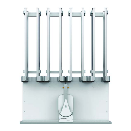
Page 25: Hardware Overview
This topic describes the hardware features of the BenchCel device. Note that the figures in this topic show a BenchCel 2R device with two stackers that support two labware racks. All the major components and functions are the same for the BenchCel 4R (four stackers) and BenchCel 6R (six stackers). - Page 26 For details, see “Adjusting the stacker gripper pressure” on page 158. Safety The clear panel that is installed on the front of the BenchCel shield device to prevent access while it is in operation. BenchCel Microplate Handler User Guide...
- Page 27 Pendant The component that is part of the safety interlock circuit, which must be closed for the BenchCel device to operate. Pressing the raised button on the pendant interrupts the safety circuit and disables the robot motors. Use this method of stopping the robot for emergencies only.
- Page 28 The structures inside the robot arms that close and open to grippers hold and release a microplate. Using the provided software, you can adjust the distance between the grippers to hold a microplate loosely or tightly. Robot grippers Back view BenchCel Microplate Handler User Guide...
- Page 29 Connects the air tubing to the BenchCel device. Compressed fitting air is used to actuate components inside the stacker head. Power Turns on or off the power to the BenchCel device. switch AC power Connects the power cord to the BenchCel device.
- Page 30 Hardware overview Stacker head At the top of the BenchCel device are stacker heads that contain infrared sensors and mechanical components that load and unload microplates during operation. The following table lists and describes the various components inside the stacker head.
- Page 31 Plate-presence sensor Rack-presence Detect the presence of labware racks. Two rack sensors are on sensors the back wall of each stacker head. Rack-presence sensors BenchCel Microplate Handler User Guide...
- Page 32 Compressed air is used to open and close the clamps. 1 2 3 4 5 6 7 8 9 10 11 12 13 14 15 16 17 18 19 20 21 22 23 24 Notches Clamps BenchCel Microplate Handler User Guide...
- Page 33 Shelves Provide leveling surfaces for the microplates, thus ensuring accurate robot gripping, during the downstacking process. Two shelves (four leveling surfaces) are inside each stacker head. Compressed air is used to move the shelves. Shelves BenchCel Microplate Handler User Guide...
- Page 34 A gripper is located on the interior bottom of each tab. The pair of grippers hold a microplate during the labware loading, unloading, downstacking, and upstacking processes. A clamp in the device opens and closes the grippers. BenchCel Microplate Handler User Guide...
-
Page 35: Integration Options For Workstations
You can integrate Agilent devices with the BenchCel Microplate Handler to create a BenchCel Workstation. The BenchCel robot can move labware to and from these devices as specified by the protocol you create. This topic lists some of the devices that can be integrated with the BenchCel Microplate Handler. Agilent devices The following figure shows an example of a BenchCel Workstation. - Page 36 Example of BenchCel Workstation: ( ) computer, ( ) Bravo Platform, ( ) BenchCel with six stackers, and ( ) Labware MiniHub The following Agilent devices can be integrated with the BenchCel Microplate Handler. Item Device Description Bravo Platform Dispenses liquids.
-
Page 37: Labware Considerations
The BenchCel device uses gripping mechanisms to hold microplates securely and repeatably in the labware rack and in the robot arms. The BenchCel device typically holds the microplates halfway between the top of the microplate and the top of the microplate skirt (5 to 10 mm above the bottom of the microplate). - Page 38 BenchCel device. Contact Agilent Technical Support about acceptable tall labware. • Extra long lid. Some microplates that have lids that extend past the microplate skirt tend to pose challenges for the BenchCel device. Contact Agilent Technical Support for guidance. Related information For more information about…...
-
Page 39: Software Description
“Hardware overview” on page 15 Safety information “Safety guidelines” on page 1 Installation requirements “Installing BenchCel Microplate Handler” on page 35 Software description About this topic This topic describes the software that you can use to set up, control, and troubleshoot the BenchCel Microplate Handler. - Page 40 VWorks Plus only. Log audit trails and manage record states • Define labware, liquid classes, and pipetting techniques • Manage labware inventory (storage devices only) • Track experiments, if applicable • Set up devices • Create protocols and forms, and run the protocols BenchCel Microplate Handler User Guide...
- Page 41 VWorks software window BenchCel ActiveX control You can use the BenchCel ActiveX control instead of the VWorks software to control the BenchCel Microplate Handler. The BenchCel ActiveX control enables the BenchCel device to interact with a third-party lab automation system.
- Page 42 Automation Control User Guide. • Set and edit teachpoints. Teachpoints are locations that the BenchCel robot will go to and from during a protocol run. You set teachpoints using the Diagnostics Controls tab when you set up the BenchCel Microplate Handler.
- Page 43 Diagnostics includes a Labware tab on the Controls page, which enables you to adjust the labware definitions. Alternatively, you can use the Labware Editor to update the labware definitions. Figure BenchCel Diagnostics Labware tab BenchCel Microplate Handler User Guide...
- Page 44 • Change general device settings. After diagnosing problems, you can change some of the device settings to repair problems or to optimize operation. Figure BenchCel Diagnostics General Settings tab Related information For more information about... See... Creating and running protocols in...
-
Page 45: Installing Benchcel Microplate Handler
“About integrating devices in a BenchCel Workstation” on page 47 • “Connecting the power source” on page 50 • “Connecting the pendant directly to the BenchCel device” on page 51 • “Connecting the pendant through the Robot Disable Hub” on page 53 •... -
Page 46: Installation Workflow
Installation workflow Installation workflow About this topic. This topic presents the sequence of installation procedures for the BenchCel Microplate Handler. Typically, an integrated BenchCel Workstation will be installed for you. Changing the configuration or components of the installed workstation might WAR NING invalidate the safety compliance and lead to personal injury or equipment damage. -
Page 47: Verifying Laboratory Requirements
• Be fixed in place, for example, casters that lock. • Sufficient clearance on the back side of the BenchCel Microplate Handler to access power, communication, and air tubing connections and for maintenance tasks. • Proper height for any operator to comfortably operate the BenchCel Microplate Handler The table must be level in the direction of the width and the depth of the platform. - Page 48 48.6 kg 64.6 kg *Approximately 30-mm of the rack height sits down inside the BenchCel stacker head. The overall height of a BenchCel device on risers with racks installed is as follows: 82.8 cm (250-mm rack) 126.0 cm (660-mm rack) 1438 cm (860-mm rack) See the following figure.
- Page 49 3 Installing BenchCel Microplate Handler Verifying laboratory requirements Figure Example of BenchCel on risers with six stacks showing height requirements of 250-mm, 660-mm, and 860-mm racks 860 mm 1438 mm 660 mm 1260 mm 250 mm 828 mm Addition of devices...
- Page 50 The supplied computer comes with a serial port and two Ethernet ports. You can connect the computer to the BenchCel Microplate Handler using either the serial port or one of the Ethernet ports. You can use the second Ethernet port to connect the...
- Page 51 If you plan to connect the computer to the BenchCel Microplate Handler and to your company’s LAN, the computer might require two Ethernet cards. Two Ethernet cards allow the BenchCel Microplate Handler to operate on an isolated network.
-
Page 52: Unpacking Benchcel Microplate Handler
Personnel requirements. Make sure two people are available to lift the BenchCel device from the crate. The BenchCel device without labware racks weighs 28 – 51 kg (61.7 – 112.4 lb), WAR NING depending on the configuration. Attempting to lift or move the BenchCel device without assistance could cause personal injury. - Page 53 Inspect the unpacked items. About installing risers The 146-mm tall risers can be installed to the underside of the BenchCel device at each end to lift the device above the table surface. The risers are required for integrating the BenchCel device with certain devices in a workstation. In you are integrating a BenchCel Microplate Handler on risers, the Agilent installer will install the BenchCel risers before mounting the robot head on the BenchCel device.
-
Page 54: Mounting The Robot
Mounting the robot Mounting the robot About this topic Typically, the BenchCel Microplate Handler will be installed for you. However, this topic provides a reference for how to mount the robot on the BenchCel device. Procedure Do not use the robot arms to lift the robot. Doing so could damage the arms. Ensure C AU T I O N that you lift the robot by the base and the head. - Page 55 Figure BenchCel robot with rotated arms to expose screw holes in the base Lift the robot head from the base to expose the remaining two screw holes in the base. While firmly supporting the robot head, install the two 45-mm M6 screws to finish securing the robot base to the x-axis carriage.
- Page 56 3 Installing BenchCel Microplate Handler Mounting the robot Figure BenchCel robot head in up position: ( ) mounting screw holes and ( ) front panel The robot head may not remain in the up position. The robot head can drop, WAR NING potentially pinching your fingers.
-
Page 57: About Integrating Devices In A Benchcel Workstation
Tighten the screws to secure the device on the integration plates. Installing the external device integration plate You can integrate an external device on the left or right side of the BenchCel device. For each external device, you must install the integration plate that is specific to that device. - Page 58 To install the external device and integration plate: Depending on whether you are integrating a device to the left or right of the BenchCel device, loosen the left or right clamp screw using the 3-mm hex wrench. See the following figure.
- Page 59 The two devices should be aligned along the y-axis (front-to-back direction) so that the BenchCel robot can place a microplate on the plate stage accurately. If the devices are not properly aligned, slide the devices along the y-axis until they appear to be correctly aligned.
-
Page 60: Connecting The Power Source
3 Installing BenchCel Microplate Handler Connecting the power source Connecting the power source About this topic This topic explains how to connect the BenchCel Microplate Handler to a grounded power source. Before you start Make sure you have the supplied power cord. -
Page 61: Connecting The Pendant Directly To The Benchcel Device
Connecting the pendant directly to the BenchCel device About this topic If you are integrating the BenchCel Microplate Handler with devices that are not equipped with safety interlock circuitry, for example, the PlateLoc Sealer or the Microplate Labeler, use the procedure in this topic to connect the emergency-stop pendant. - Page 62 Connecting the pendant directly to the BenchCel device Procedure To connect the pendant directly to the BenchCel device: Connect the pendant cable to the pendant port on the back of the BenchCel device. Related information For more information about… See…...
-
Page 63: Connecting The Pendant Through The Robot Disable Hub
Connecting the pendant through the Robot Disable Hub About this topic Read this topic if you are integrating the BenchCel Microplate Handler with other devices that are equipped with safety interlock circuitry, such as the Bravo Platform. This topic describes how to connect the emergency-stop pendants for the integrated devices through the Robot Disable Hub, which provides a main emergency-stop control for the workstation. - Page 64 Any unused Pendants connectors require E-stop jumpers to close the interlock circuit. IMPORTANT Example of connections using Robot Disable Hub The following figure and table provide an example of connecting the BenchCel device and the Bravo Platform through the Robot Disable Hub. 00220...
-
Page 65: Connecting And Disconnecting The Air Source
About this topic Compressed air is used to move parts inside the BenchCel Microplate Handler. This topic explains how to connect the BenchCel Microplate Handler to the air source and check the connections for leaks before use. Before you start Make sure you have the supplied air tubing. - Page 66 3 Installing BenchCel Microplate Handler Connecting and disconnecting the air source Figure Air tubing connection on the back of the BenchCel Microplate Handler To air source (house, cylinder, or pump) Checking the air connections To check the air connections: With the air source turned off, gently tug the air tubing at each connection.
-
Page 67: Connecting The Computer
• Ethernet switch (supplied) for Ethernet connections only Connecting the controlling computer You can connect the computer to the BenchCel Microplate Handler in one of the following ways: • Serial connection. You can use the supplied RS-232 DB9 serial cable to connect the computer to the BenchCel Microplate Handler. - Page 68 Ethernet connection. You can use the supplied Ethernet cable to connect the computer to the BenchCel Microplate Handler. The Agilent configured computer has two Ethernet ports. You can use one port to connect to the BenchCel Microplate Handler and the other to connect to your company network.
- Page 69 Configuring the computer network card (Ethernet connection only) The computer configured by Agilent Technologies is already set up to communicate with the BenchCel Microplate Handler. No change to the network card IP address is required. If you are using a computer that was not configured by Agilent Technologies, make sure the value of the network card IP address and subnet mask are as follows: •...
- Page 70 3 Installing BenchCel Microplate Handler Connecting the computer Related information For more information about… See… The controlling computer requirements “Verifying laboratory requirements” on page 37 The Ethernet switch The Ethernet switch user documentation IP addresses The Microsoft Windows user documentation Installing the BenchCel Microplate “Installation workflow”...
-
Page 71: Installing The Shield
Installing the shield About this topic This topic explains how to install the safety shield on the front of the BenchCel Microplate Handler. Additional shields may be required depending on the workstation configuration. Typically, the BenchCel Microplate Handler and workstation safety equipment will be installed for you. -
Page 72: Setting Up The Benchcel
Safety shield on BenchCel Microplate Handler with two stackers (top view) Top view - back Insert screws Tighten the screws using the M3 hex wrench. Repeat steps 1 to 3 for each pair of stackers on the BenchCel Microplate Handler. Related information For more information about… See…... - Page 73 4 Setting up the BenchCel device This chapter explains how to set up the BenchCel Microplate Handler for operation. This chapter contains the following topics: • “Setup workflow” on page 64 • “Starting up and shutting down” on page 66 •...
-
Page 74: Setup Workflow
The following table presents the steps for setting up the BenchCel Microplate Handler. After setting up the BenchCel Microplate Handler for the first time, you will not likely change any of the settings in the procedure unless you add a device, replace a device, or move the BenchCel Microplate Handler. - Page 75 For this task… See… “Starting up and shutting down” on page 66 Start up the workstation. “Creating BenchCel device in the VWorks software” on page 68 Create a device file and add the BenchCel device in VWorks. “Creating profiles” on page 76 Create a profile.
-
Page 76: Starting Up And Shutting Down
The BenchCel safety interlock circuit must be closed for the device to operate. IMPORTANT To start up the BenchCel Microplate Handler: On the back of the BenchCel Microplate Handler, press the power switch to the on (I) position. Figure Power switch on the BenchCel Microplate Handler (back) Every time you turn on the BenchCel Microplate Handler, the robot homes (the robot is sent to the factory-defined home position for each axis of motion). - Page 77 Turn off the compressed air to the BenchCel Microplate Handler and other devices. Turn off the BenchCel Microplate Handler. To do this, on the back of the device, press the power switch to the off (O) position.
-
Page 78: Creating Benchcel Device In The Vworks Software
If your computer was configured by Agilent Technologies. The correct device configuration is already set up for communication with the BenchCel Microplate Handler. You are not required to create a new BenchCel device in the software unless you want to reference different profiles, integrate additional devices with the workstation, or change the rack size. - Page 79 Creating BenchCel device in the VWorks software Creating a device file If you are setting up the BenchCel Microplate Handler for the first time, you will create a device file. You add the BenchCel device and the external devices to the device file.
- Page 80 On the Device File tab, expand the BenchCel device icon to show the list of stackers, and then click the Stacker 1 icon. The corresponding stacker properties appear.
- Page 81 For example, type 660 if you are using a 660-mm tall rack. Do not change the default value of the Teachpoint for robot BenchCel property. For IMPORTANT example, the stacker 1 teachpoint identity is 1, the identity of stacker 2 is 2, and so forth.
- Page 82 Creating BenchCel device in the VWorks software Specifying BenchCel accessibility at other devices For any device in the workstation that the BenchCel robot will access, use the following procedure to set the Teachpoint for robot Agilent BenchCel property in the device file after you set the BenchCel teachpoint at the given device.
-
Page 83: Opening Benchcel Diagnostics
4 Setting up the BenchCel device Opening BenchCel Diagnostics Related information For information about… See… VWorks software VWorks Automation Control User Guide Setting up BenchCel Microplate “Setup workflow” on page 64 Handler Profiles “Creating profiles” on page 76 Teachpoints “Setting and managing teachpoints” on... - Page 84 4 Setting up the BenchCel device Opening BenchCel Diagnostics The device’s diagnostics dialog box opens. Figure BenchCel Diagnostics window with Profiles page displayed Note: For VWorks 14.0 and later versions, the Profiles page contains log areas. BenchCel Microplate Handler User Guide...
-
Page 85: Creating Profiles
4 Setting up the BenchCel device Opening BenchCel Diagnostics Related information For information about… See… VWorks software VWorks Automation Control User Guide Setting up BenchCel Microplate “Setup workflow” on page 64 Handler Profiles “Creating profiles” on page 76 Teachpoints “Setting and managing teachpoints” on... -
Page 86: Creating Profiles
If you are using a computer other than one configured by Agilent Technologies, you must create a BenchCel profile. This topic describes how to create BenchCel profiles. - Page 87 Select the correct Ethernet adapter for the device connection. A list of devices appear. In the list of devices that appear, select the BenchCel device. If you have multiple BenchCel devices on the network, use the MAC Address to identify the BenchCel device you want.
- Page 88 This option helps to optimize communication over the serial connection. If you want to create a profile for a BenchCel Microplate Handler that has a different number of stacks than the one connected to the controlling computer, set the Number of stacks value.
- Page 89 4 Setting up the BenchCel device Creating profiles Note: The default teachpoint file name is Teachpoints_<profilename>.xml, where <profilename> is the name of the profile. Append the teachpoint file name with the word backup, and then click Save. Note: The Teachpoint File area displays the file storage location.
- Page 90 C AU T I O N teachpoints before using a profile. If you are setting up the BenchCel Microplate Handler for the first time, return to “Creating BenchCel device in the VWorks software” on page 68 and select the profile name (step 5).
- Page 91 4 Setting up the BenchCel device Creating profiles Figure Log area in Profiles tab Related information For information about See... Adding a device in VWorks software “Creating BenchCel device in the VWorks software” on page 68 Setting teachpoints “Setting and managing teachpoints” on...
-
Page 92: Initializing The Device
VWorks window. Before you start Ensure that you have added the BenchCel device to a VWorks device file and that you have a valid BenchCel profile. Initializing the device in Diagnostics To initialize a profile in BenchCel Diagnostics: In the VWorks window, open the device file for the profile that you want to initialize. - Page 93 Open. In the Devices area, highlight the device that you want to establish communication with, and verify that the correct profile is selected in the BenchCel Properties area. Click Initialize selected devices or Initialize all devices.
-
Page 94: Setting And Managing Teachpoints
The location can be on an external device or a platepad. You set, edit, and save teachpoints in BenchCel Diagnostics. The teachpoints are displayed as plus signs ( in the graphical display area in the BenchCel Diagnostics dialog box. - Page 95 4 Setting up the BenchCel device Setting and managing teachpoints You must use one teachpoint file for each BenchCel device. If you integrate a new device with the BenchCel Microplate Handler, you can add the new teachpoints to the existing file. If you have multiple BenchCel devices in a workstation, you must create a teachpoint file for each BenchCel device in the workstation.
-
Page 96: Determining The Teachpoint Coordinates
123. Open BenchCel Diagnostics for the BenchCel device that you are setting up. On the Profiles page, look in the Teachpoint File area to make sure the correct teachpoint file is loaded. You will be adding new teachpoints to this file. - Page 97 In the graphical display area, click Stacker at the top of the rack that contains the spare microplates. In the menu that appears, click Load plates. The BenchCel device moves the stack down and holds the stack in the stacker grippers, or supports the stack on the stacker shelf, as specified in the labware definition.
- Page 98 4 Setting up the BenchCel device Setting and managing teachpoints Click Go Home. The robot head moves to its home position at the center of the BenchCel Microplate Handler. Note: The microplate is still in the robot grippers from step In the Motors Enabled area, clear the check boxes for X and Theta to disable the x-axis and theta-axis motors.
- Page 99 47). • To move the robot head up or down in small, precise increments, open BenchCel Diagnostics. On the Controls page Jog/Teach tab, select the jog increment from the corresponding list, and then click Up ( ) or Down ( Click to select jog increment.
-
Page 100: Locking The Device Positions
Before you record the teachpoint, lock the devices in their positions. To lock the devices in their positions: Tighten the BenchCel integration plate clamp screw using the 3-mm hex wrench. Check the teachpoint coordinates again. See “Determining the teachpoint coordinates”... -
Page 101: Recording The Teachpoint Coordinates
4 Setting up the BenchCel device Setting and managing teachpoints Recording the teachpoint coordinates To record the teachpoint coordinates in BenchCel Diagnostics: Ensure the robot is holding the microplate at the teachpoint location. On the Controls page Jog/Teach tab, click New teachpoint. - Page 102 4 Setting up the BenchCel device Setting and managing teachpoints Set the remaining teachpoint parameters and options in the Teachpoint Details dialog box: Setting Comment Name Type a one-word name for the teachpoint. For example, if the teachpoint is on an integrated Microplate Labeler, you might want to name the teachpoint Labeler.
- Page 103 Use this setting if the teachpoint area is narrower than the robot grippers open position. (To see this value, click Save and exit, and then click the Labware tab in the BenchCel Diagnostics Control tab.) Note: This value is used only at the teachpoint and not during other operations.
- Page 104 Click Save and Exit to save the teachpoint in the teachpoint file and close the Teachpoint Details dialog box. On the Controls page in BenchCel Diagnostics, the new teachpoint appears in the graphical display area as a plus sign (...
- Page 105 After the motors are enabled, the robot head moves to the center of the BenchCel device, and the robot arms are perpendicular to the x-axis. The robot grippers are still holding the spare microplate you used to set the teachpoint.
-
Page 106: Verifying The Teachpoints
119 “Installing and uninstalling the labware racks” on page 123. In BenchCel Diagnostics, click the Controls tab, and select the desired labware definition from the Labware list. In the graphical display area, click the plus sign ( ) at both of the following locations: •... -
Page 107: Editing Existing Teachpoints
Adjust settings on the devices To edit an existing teachpoint: In BenchCel Diagnostics, click the Profiles tab, and verify that the correct teachpoint file is loaded. Click the Controls tab. In the graphical display area, double-click the plus sign ( of the teachpoint you want to edit. - Page 108 Setting and managing teachpoints Deleting teachpoints To delete a teachpoint: In BenchCel Diagnostics, click the Profiles tab, and verify that the correct teachpoint file is loaded. In the graphical display area, double-click the plus sign ( ) of the teachpoint you want to delete.
-
Page 109: Setting Sensor Thresholds
5 Setting sensor thresholds This chapter describes how to set the sensor thresholds correctly for the specific type of labware you are using. This chapter contains the following topics: • “Overview for setting sensor thresholds” on page 100 • “Calculating the Plate presence threshold” on page 102 •... -
Page 110: Overview For Setting Sensor Thresholds
For example, the thresholds must be accurate to ensure proper upstacking and downstacking of the labware. You must set the thresholds for the labware type before using the labware in a BenchCel protocol run. - Page 111 Workflow for setting sensor thresholds Before you start Make sure you have three spare microplates for each BenchCel stacker head. For example, if the BenchCel Microplate Handler has six stacker heads, you should have 18 microplates. Make a copy of the provided “Worksheet for setting sensor thresholds”...
-
Page 112: Calculating The Plate Presence Threshold
Install a labware rack at each stacker head, and place three microplates in each labware rack. The microplates should rest on top of the stacker grippers. (See “Filling and emptying the labware racks” on page 119.) Do not click Load All in BenchCel Diagnostics. IMPORTANT BenchCel Microplate Handler User Guide... - Page 113 5 Setting sensor thresholds Calculating the Plate presence threshold In BenchCel Diagnostics on the Controls page, click the Labware tab. In the Sensors area, set the initial values as follows: • Plate presence threshold at 225 units. • Intensity at 100%.
- Page 114 The Plate presence reading can vary depending on the Stack Holding Method, which is IMPORTANT specified in the Labware Editor. For greater precision, use the stacker grippers for the Stack Holding Method. On the Controls page, click Load All. BenchCel Microplate Handler User Guide...
- Page 115 Plate presence threshold = (P unloaded loaded In the following example, the calculated threshold is 91. unloaded loaded Plate presence threshold On the Jog/Teach tab, type the calculated Plate presence threshold, and then click Apply & save. BenchCel Microplate Handler User Guide...
- Page 116 Worksheet for sensor thresholds “Worksheet for setting sensor thresholds” on page 113 Labware definitions and the Labware VWorks Automation Control Setup Guide Editor Filling and emptying the labware racks “Filling and emptying the labware racks” on page 119 BenchCel Microplate Handler User Guide...
-
Page 117: Determining The Optimum Orientation Sensor Offset
Determine the midpoint height (mm) of the microplate. To do this, measure from the top of the microplate skirt to the top of the microplate and divide by 2. Measure the height (mm) of the microplate skirt. Add the values from step a and step b. BenchCel Microplate Handler User Guide... - Page 118 In the following example, the Notch Sensors values indicate that the microplate has two notches (3 and 7) and two corners (76 and 63). BenchCel Microplate Handler User Guide...
- Page 119 Move to sensor. Check the Notch Sensors readings on the Jog/Teach tab. The notches should have much lower readings than the corners. In addition, the difference between the notch readings and corner readings should be at a maximum. BenchCel Microplate Handler User Guide...
- Page 120 Worksheet for sensor thresholds “Worksheet for setting sensor thresholds” on page 113 Previous step in this workflow “Calculating the Plate presence threshold” on page 102 Next step in this workflow “Calculating the Orientation threshold” on page 111 BenchCel Microplate Handler User Guide...
-
Page 121: Calculating The Orientation Threshold
At each stacker, determine the highest reading for the notch and lowest reading for the corner as follows: In BenchCel Diagnostics, click the Controls tab. In the graphical display area click Stacker 1, and then click Move to sensors. On the Jog/Teach tab in the Stacker Sensors area, select stack 1 from the list. - Page 122 Previous steps in this workflow “Calculating the Plate presence threshold” on page 102 • “Determining the optimum Orientation sensor offset” on page 107 Worksheet for sensor thresholds “Worksheet for setting sensor thresholds” on page 113 BenchCel Microplate Handler User Guide...
-
Page 123: Worksheet For Setting Sensor Thresholds
Highest reading among all the stacks (P ): _________________ unloaded Determine the Plate presence readings when the microplates are loaded After loading the microplates at each stack (Load All in BenchCel Diagnostics), record the Plate presence readings for each stack. Stack 1 Stack 2... - Page 124 Record the lowest corner reading for each stack. Stack 1 Stack 2 Stack 3 Stack 4 Stack 5 Stack 6 Lowest reading among all stacks (Corner ): ____________ lowest Orientation threshold Orientation threshold = (Notch + Corner )/2 = __________ highest lowest BenchCel Microplate Handler User Guide...
-
Page 125: Preparing For A Run
6 Preparing for a run This chapter describes how to prepare for a protocol run on the BenchCel Microplate Handler. All of the procedures in this chapter can be performed by someone with operator privileges. This chapter contains the following topics: •... -
Page 126: Workflow For Operating The Benchcel Microplate Handler
6 Preparing for a run Workflow for operating the BenchCel Microplate Handler Workflow for operating the BenchCel Microplate Handler About this topic This topic presents the workflow for operating the BenchCel Microplate Handler. Before you start Make sure that you have: •... -
Page 127: Handling The Labware Racks
A rack that is fully loaded with labware can be heavy. Grasp the rack handle firmly to C AU T I O N prevent the rack from slipping or tilting. To carry a rack, firmly grasp the rack by the handle as the following figure shows. Figure Carrying a front-load rack BenchCel Microplate Handler User Guide... - Page 128 119 Mounting the labware racks onto the “Installing and uninstalling the labware device and removing the racks from racks” on page 123 the device Labware definitions and the Labware VWorks Automation Control Setup Guide Editor BenchCel Microplate Handler User Guide...
-
Page 129: Filling And Emptying The Labware Racks
Front-load racks. The rack can be mounted on the BenchCel Microplate Handler or placed on a flat, level surface. For details on how to mount the racks or remove the racks from the BenchCel Microplate Handler, see “Installing and uninstalling the labware racks” on page 123. - Page 130 Ensure that the bottom labware in the stack rests on the rack stacker grippers. To remove labware from a standard or top-load rack: If possible, remove the rack from the device, and place the rack on a flat, level surface. BenchCel Microplate Handler User Guide...
- Page 131 Stacker gripper To place labware into a front-load rack: If the rack is mounted on the BenchCel device, verify that the stack is in the unloaded state. To unload the stack, open BenchCel Diagnostics. On the Control page, click Stacker, and then choose Unload Plates.
- Page 132 To close the doors, press the thumb tabs inward until the doors snap shut. To remove labware from a front-load rack: If the rack is mounted on the BenchCel device, verify that the stack is in the unloaded state. To unload the stack, open BenchCel Diagnostics. On the Control page, click Stacker, and then choose Unload Plates.
-
Page 133: Installing And Uninstalling The Labware Racks
Rack Stacker head Before you start Make sure the BenchCel power and compressed air are turned on before you install or IMPORTANT uninstall a labware rack. When lifting the labware rack onto and off of the stacker head, use both hands to grasp the rack securely around the four corners near the base. - Page 134 Figure Safely lifting a labware rack The rack-release button at the top of the stacker head on the BenchCel device is C AU T I O N sensitive to static electricity. Static electricity can cause a potential loss of motor control and loss of communication with the BenchCel device.
- Page 135 Installing a labware rack on the stacker head (closeup view without labware) Uninstalling labware racks Before you can remove a mounted rack, you must first unlock the rack. When you unlock the rack, two pins in the stacker head retract, as the following figure shows. BenchCel Microplate Handler User Guide...
- Page 136 At the BenchCel Microplate Handler, verify that the stack is unloaded. To unload the stack, open BenchCel Diagnostics. On the Controls page in the graphical display area, click Stacker at the top of the rack that you want to remove, and then choose Unload Plates.
- Page 137 Installing and uninstalling the labware racks • In BenchCel Diagnostics, click the Controls tab. In the graphical display area, at the top of the rack that you want to unlock, click Stacker, and then choose Unlock rack. A click sounds as the locks retract.
-
Page 138: Performing Pre-Run Checks
Performing pre-run checks Performing pre-run checks About this topic Before you start a protocol run, you should check the BenchCel Microplate Handler to ensure optimum operation. Perform the following procedure before each protocol run. Procedure To check that the BenchCel and integrated devices are ready for a run: Ensure the labware racks are filled with the correct labware. -
Page 139: Maintenance And
7 Maintenance and troubleshooting This chapter describes how to maintain the BenchCel Microplate Handler and provides troubleshooting information. This chapter contains the following topics: • “Routine maintenance” on page 130 • “Cleaning up after a protocol run” on page 132 •... -
Page 140: Routine Maintenance
Use a clean soft cloth or laboratory wipes to clean up spills on any part of the device immediately after a protocol run. Clean the BenchCel device weekly or as needed. Use standard laboratory wipes and a mild detergent or isopropyl alcohol to clean the exterior painted white surfaces and the metal surfaces of dust, grime, chemical deposits, and other debris. - Page 141 • Stacker gripper pressure. Make sure the pressure is set correctly. On the Controls page in BenchCel Diagnostics, click the Jog/Teach tab, and check the Air reading. Integrated device For routine maintenance of the devices integrated with the BenchCel device, see the user documentation for the corresponding device.
-
Page 142: Cleaning Up After A Protocol Run
Procedure Make sure you clean up spilled liquids immediately. Do not use harsh abrasives, C AU T I O N corrosive cleaning agents, or metal brushes to clean any BenchCel component or accessory. To clean up after a run: Follow the VWorks prompts for post-run software procedures, such as unloading the microplates. - Page 143 VWorks software run logs and VWorks Automation Control User Guide protocols Logging in and out of the VWorks VWorks Automation Control User Guide software Shutting down the BenchCel “Shutting down the BenchCel Microplate Microplate Handler Handler” on page 67 BenchCel Microplate Handler User Guide...
-
Page 144: Replacing The Fuse
Use only the specified fuse type: 5 A, 250 V, 5 mm x 20 mm, fast acting. You can order fuses from Agilent Technologies. On the BenchCel control panel, verify the power rating (120 V or 230 V) for your region matches the display on the fuse enclosure. -
Page 145: Replacing The Fuse
Fuse cartridge (A) Right side with correctly installed fuse, B) Left side with spare fuse Ensure the fuse is installed correctly in the cartridge. Otherwise, the device might not IMPORTANT turn on. Slide the fuse cartridge back into the fuse enclosure. BenchCel Microplate Handler User Guide... - Page 146 Ensure that the cartridge is pushed in all the way, and press the enclosure cover securely into the closed position. Plug in the power cable at the rear panel connector, and then start up the BenchCel Microplate Handler. Related information For information about...
-
Page 147: Hardware Problems
About this topic This topic lists possible hardware problems, the causes of the problems, and ways to resolve the problems. If you are still experiencing problems with the BenchCel Microplate Handler after trying the solutions, contact Agilent Technical Support. Hardware problems... - Page 148 The rack-release The stack of microplates are still In BenchCel Diagnostics, click the Controls button does not turn loaded. tab. In the graphical display area at the top of green and the labware...
-
Page 149: Software Error Messages
About this topic This topic lists possible software error messages, the causes of the errors, and ways to resolve the errors. If you are still experiencing problems with the BenchCel Microplate Handler after trying the solutions, contact Agilent Technical Support. - Page 150 The device was not The BenchCel device is not To connect the device: found connected to the controlling Turn off the BenchCel Microplate Handler computer, or the incorrect profile is and exit the VWorks software. used. Ensure the BenchCel Microplate Handler is connected to the controlling computer.
- Page 151 The Robot gripper offset parameter Correct the Robot gripper offset value in the value is incorrect. Labware Editor or in BenchCel Diagnostics. An 8-mm offset works for most labware. No microplate is available at the Make sure you load or place labware at the pickup location.
- Page 152 The microplate is loaded in the Check the microplate orientation (notch wrong orientation. selections) in the Labware Editor or in BenchCel Diagnostics. Make sure you load the microplates in the rack accordingly. Notch selection is incorrect in the Verify the notch selection in the Labware labware definition.
- Page 153 123 for the procedure. The rack-presence sensor is not In the BenchCel Diagnostics, click the General able to detect the rack because one Settings tab, and adjust the value in the Rack of the following: sensor threshold box.
- Page 154 Home the robot, and then move the robot in respond as expected. the same axis. If the robot moves, continue If the robot does not move, quit the VWorks software and restart the BenchCel Microplate Handler. If the problem persists, contact Agilent Technical Support.
- Page 155 Wrong plate type The microplate in the stack is Check the labware selected in the Labware different from the labware selected Editor or in the BenchCel Diagnostics Controls in the software. tab. The microplate is loaded in the Check the microplate orientation (notch wrong orientation.
-
Page 156: Diagnostic Tools
Sending the robot to the home position The home position is where the robot head is at the center of the BenchCel Microplate Handler and the robot arms are perpendicular to the x-axis. You send the robot to the home position if you want the robot out of the way in a safe position. -
Page 157: Disabling And Enabling The Robot Motors
Note: If a labware definition is selected when you click Home motors, the robot grippers return to the Gripper open position defined for the selected labware. To home the robot: On the BenchCel Diagnostics Controls page, click the Jog/Teach tab. Click Home motors. Disabling and enabling the robot motors Disabling the robot motors allows you to move the robot by hand, making it easier to set and edit teachpoints. -
Page 158: Jogging The Robot
You can jog the robot to fine-tune its position when creating and editing teachpoints. To jog the robot: On the BenchCel Diagnostics Controls page, click the Jog/Teach tab. Enable the robot motors. See “Disabling and enabling the robot motors” on page 147. -
Page 159: Changing The Robot Speed
Diagnostic tools Changing the robot speed The speed you select in BenchCel Diagnostics applies only to the robot commands in BenchCel Diagnostics (Jog, Move, Transfer, and so on). If the robot is holding a microplate, the slower of the following will be applied: the speed you selected in the Labware Editor or the speed you selected in BenchCel Diagnostics. - Page 160 Note: The factory speed settings for all three axes are Slow 20%, Medium 40%, Fast 80%. Note: The speed settings apply to the speeds you select in BenchCel Diagnostics, Labware Editor, and the VWorks Options dialog box. Click OK to save the changes.
-
Page 161: Moving Plates Between Teachpoints
To move plates between teachpoints: Manually place a microplate at one of the two teachpoints. In BenchCel Diagnostics, click the Controls tab, and then select the Slow speed. In the graphical display area, click the plus sign ( ) at either of the following: •... -
Page 162: Opening And Closing Clamps
The clamps close and open the stacker grippers automatically during the loading, unloading, downstacking, and stacking procedures. When diagnosing problems or after an aborted run, you can use the commands in BenchCel Diagnostics to open or close the clamps (stacker grippers). For example, you might want to open the clamps (stacker grippers) to remove a microplate. -
Page 163: Extending And Retracting Shelves
The shelves extend and retract automatically during the downstacking and upstacking processes. When diagnosing problems or after an aborted run, you can use the commands in BenchCel Diagnostics to extend or retract the shelves. Retracting the shelves might cause the microplate or stack of microplates to drop. -
Page 164: Changing Labware Parameters
Labware Editor. For example, you can change the stacking thickness, gripper offsets, notch specification, and lid specifications. Note: Changes you make to the labware parameters in BenchCel Diagnostics are also updated in the Labware Editor. Before you start Calculate the values for the labware sensor thresholds. - Page 165 On the Controls page, select the labware definition from the Labware list. Click the Labware tab and make your changes to the labware parameters. • Plate Dimensions. See “BenchCel Diagnostics - Labware tab” on page 173. • Sensors. See “Setting sensor thresholds” on page •...
-
Page 166: Changing The General Settings
C AU T I O N protocols. The changes are stored in the BenchCel flash memory. The changes you make to the C AU T I O N general settings will take affect any time you are using this BenchCel device regardless of profile, protocol file, or device file. - Page 167 VWorks Plus only. If an audit trail is being logged, the Audit Comment dialog box opens. Select or type the audit comment, and then click OK. Related information For more information about… See… How to open BenchCel Diagnostics “Opening BenchCel Diagnostics” on page 73 How to report a problem “Reporting problems” on page 162...
-
Page 168: Adjusting The Stacker Gripper Pressure
Although the required air pressure from your lab is 0.65 to 0.69 MPa (95 to 100 psi), the BenchCel Microplate Handler down-regulates the pressure inside the device. Typically, no adjustment is required for the internal air pressure. You might want to adjust the pressure when troubleshooting Load Plate problems or when you want to load different labware on the same BenchCel Microplate Handler. - Page 169 Adjusting the stacker gripper pressure Adjusting the internal air pressure To adjust the internal air pressure: At the front of the BenchCel Microplate Handler, lift the magnetic circular cover to gain access to the air-pressure regulator. Figure Accessing the BenchCel air-pressure regulator...
- Page 170 On the Jog/Teach tab, check the air pressure value. A valid air pressure value displays only when the stacker grippers are closed. Figure Jog/Teach tab At the front of the BenchCel Microplate Handler, turn the lock nut clockwise to lock the air-pressure regulator knob. This prevents accidental adjustments. Figure Locking the air-pressure regulator Turn clockwise to lock.
- Page 171 Related information For information about… See… Air pressure requirements “Compressed air requirements” on page 39 How to open BenchCel Diagnostics “Opening BenchCel Diagnostics” on page 73 How to report a problem “Reporting problems” on page 162 Hardware problems “Hardware problems” on page 137 Software error messages “Software error messages”...
-
Page 172: Reporting Problems
Contacting technical support If you find a problem with the BenchCel Microplate Handler, contact Agilent Technical Support. For contact information, go to https://www.agilent.com/en-us/contact-us/ page. - Page 173 7 Maintenance and troubleshooting Reporting problems Figure BenchCel device front and back views Reporting software problems When you contact Agilent Technical Support, make sure you provide the following: • Short description of the problem • Software version number • Error message text (or screen capture of the error message dialog box) •...
- Page 174 For more information about… See… Resolving hardware problems “Hardware problems” on page 137 Resolving software errors “Software error messages” on page 139 Safety information “Safety guidelines” on page 1 Hardware description “Hardware overview” on page 15 BenchCel Microplate Handler User Guide...
-
Page 175: Reference
“BenchCel Diagnostics - Jog/Teach tab” on page 170 • “BenchCel Diagnostics - Labware tab” on page 173 • “BenchCel Diagnostics - General Settings tab” on page 178 • “BenchCel Diagnostics - Profiles tab” on page 179 • “Teachpoint Details dialog box” on page 182... -
Page 176: Rack-Release Button Indicator Light
Color of indicator light Meaning Green The labware rack is installed correctly on the BenchCel Microplate Handler and the stack of microplates are unloaded. • The stack of microplates are ready for processing. •... -
Page 177: Benchcel Diagnostics - Controls Tab
BenchCel Diagnostics - Controls tab The Controls tab contains the following areas: • “Graphical display area” on page 167 • “BenchCel Diagnostics - Jog/Teach tab” on page 170 • “BenchCel Diagnostics - Labware tab” on page 173 Graphical display area Table... - Page 178 Specifies the relative speed at which the robot head and arms moves: Fast, Medium, and Slow. “Changing the robot speed” on page 149 This speed control applies only in BenchCel Diagnostics. Load All Places all the stacks of labware on the shelves in preparation for a protocol run.
- Page 179 A Quick reference BenchCel Diagnostics - Controls tab Control or command Description Pick from <teachpoint> Picks up the plate from the selected teachpoint, and then the robot backs away from the teachpoint into the safe zone. Place at <teachpoint> Moves the robot from its current position and places the plate at the selected teachpoint.
-
Page 180: Benchcel Diagnostics - Jog/Teach Tab
A Quick reference BenchCel Diagnostics - Jog/Teach tab BenchCel Diagnostics - Jog/Teach tab You use the Jog/Teach tab for the following procedures: • “Setting and managing teachpoints” on page 84 • “Setting sensor thresholds” on page 99 • “Sending the robot to the home position” on page 146 •... - Page 181 Go Home Moves the robot head to the home position, which is at the center of the BenchCel Microplate Handler, and the robot arms are perpendicular to the x-axis. You send the robot to the home position if you want the robot out of the way in a safe position.
- Page 182 A Quick reference BenchCel Diagnostics - Jog/Teach tab Command Description Home Motors Sends the robot to the factory-defined home position for each axis of motion. The homing process recalibrates the robot position along each axis. Home the robot if you notice that the robot is not accurately picking up or placing plates.
-
Page 183: Benchcel Diagnostics - Labware Tab
A Quick reference BenchCel Diagnostics - Labware tab BenchCel Diagnostics - Labware tab You can use the Labware tab to perform the following procedures: • “Setting sensor thresholds” on page 99 • “Changing labware parameters” on page 154 The settings in the Labware tab are also available in the Labware Editor. - Page 184 A Quick reference BenchCel Diagnostics - Labware tab Parameters Description Stacking thickness The thickness (mm) of two stacked plates minus the thickness of one plate. For example: Thickness of two stacked plates (x) = 23.14 mm Thickness of one plate = 14.14 mm Stacking thickness: 23.14 mm - 14.14 mm = 9.00 mm...
- Page 185 A Quick reference BenchCel Diagnostics - Labware tab Plate Offsets (mm) area Parameters Description Robot gripper offset The distance (mm) from the bottom of a microplate to where the robot grippers will hold the microplate. Stacker gripper offset The distance (mm) from the bottom of a microplate to where the stacker grippers will hold the microplate.
- Page 186 A Quick reference BenchCel Diagnostics - Labware tab Options Description Plate check boxes Indicates that the plate A1 corner has a notch. Clear the check box if the A1 corner does not have a notch. Upper right corner Indicates that the plate upper right corner has a notch.
- Page 187 A Quick reference BenchCel Diagnostics - Labware tab Parameters Description Lid departure height The height (mm) above the bottom of the plate to which the lid is lifted. Gripper holding lid position The distance (mm) the grippers move inward from home position when holding a microplate lid.
-
Page 188: Benchcel Diagnostics - General Settings Tab
Home robot after protocol The option to return the robot to its home position run finishes after the protocol run is finished. This option applies to all BenchCel devices that are controlled by the same computer running the VWorks software. Speed settings... -
Page 189: Benchcel Diagnostics - Profiles Tab
A Quick reference BenchCel Diagnostics - Profiles tab Parameters Description Apply The command that applies the changes so that the new values are used. BenchCel Diagnostics - Profiles tab You use the Profiles tab to create and initialize profiles. See “Creating profiles”... - Page 190 Specifies which COM port on the computer is connected to the device. Use flow control Allows the BenchCel device to stop the flow of data from the computer before it overruns the device communication buffer. Select this option to optimize communication via the serial connection.
- Page 191 BenchCel Diagnostics - Profiles tab Selections and commands Description Number of stacks Enables you to create a profile for a BenchCel device that has a different number of stacks than the one connected to the controlling computer. IMPORTANT During initialization, the software automatically detects the actual number of stacks on the BenchCel Microplate Handler.
-
Page 192: Teachpoint Details Dialog Box
The angle that the robot arms are from their home position, in degrees. A positive value moves the arms counterclockwise from the home position. A negative value moves the arms clockwise from the home position. The range of movement is from -115° to 115°. BenchCel Microplate Handler User Guide... - Page 193 Note: This value applies when the robot is holding a microplate. When it is not holding a microplate, the robot will approach the teachpoint at the height of the teachpoint, unless you select the Respect approach height when not holding a plate option. BenchCel Microplate Handler User Guide...
- Page 194 CAUTION If you want to clear this check box, verify that the grippers will not run into the locating tabs of the stage. Otherwise, clearing this check box can result in a crash. BenchCel Microplate Handler User Guide...
- Page 195 For example, when moving labware to and from a multi-shelf device such as the Vertical Pipetting Station, this option prevents the robot from colliding with the shelf above the target teachpoint. BenchCel Microplate Handler User Guide...
- Page 196 In this guide This guide describes the BenchCel Microplate Handler R-Series models. This guide covers: • Safety • Installation • Setup and operation • Troubleshooting and maintenance. www.agilent.com © Agilent Technologies, Inc. 2020 November 2020 *G5580-90000* G5580-90000 Revision B...