
Subscribe to Our Youtube Channel
Related Manuals for Planet WGSD-1022


Summary of Contents for Planet WGSD-1022
- Page 1 8-Port 10/100Mbps + 2 Gigabit TP/SFP combo Managed Ethernet Switch WGSD-1022 User's Manual...
-
Page 3: Fcc Warning
Disclaimer PLANET Technology does not warrant that the hardware will work properly in all environments and applications, and makes no warranty and representation, either implied or expressed, with respect to the quality, performance, merchantability, or fitness for a particular purpose. - Page 4 Revision PLANET 8-Port 10/100Mbps + 2 Gigabit TP/SFP combo Managed Ethernet Switch User's Manual MODEL: WGSD-1022 ISION: 1.0 (AUGUST.2006) Part No. 2081-A34030-000...
-
Page 5: Table Of Contents
TABLE OF CONTENTS 1. INTRO DUCTION ..........................16 ket Contents..........................16 to Use This Manual........................16 Product Feature ..........................17 Prod uct Specification ........................18 2. INSTA LLATION ........................... 20 Product Description........................20 2.1.1 Product Overview ......................20 2.1.2 Switch Front Panel......................21 2.1.3 LED Indications........................ - Page 6 4.4.2 Port setting........................48 4.4.3 Ports to VLAN ........................49 4.4.4 VLAN to Ports ........................50 4.4.5 GVRP ..........................51 4.5 Statistics............................. 54 4.5.1 RMON Statisti ........................54 4.5.2 RMON History........................56 4.5.3 RMON Alarm........................58 4.5.4 RMON Events........................61 4.5.5 Port Utilization........................
- Page 7 4.10 Multicast..........................110 4.10.1 IGMP Snooping ......................110 4.10.2 Bridge Multicast ......................111 4.10.3 Bridge Multicast Forward All ..................114 4.11 SNMP............................. 115 4.11.1 Global Parameters ....................... 115 4.11.2 Views ........................... 116 4.11.3 Group Profile........................ 118 4.11.4 Group Membership ...................... 119 4.11.5 Communities ........................
- Page 8 5.3.6 ip https authentication ....................156 5.3.7 show authentication methods ..................157 5.3.8 password ........................158 5.3.9 enable password......................159 5.3.10 username........................159 5.3.11 show users accounts....................160 5.4 A ddress Table Commands ....................... 161 5.4.1 bridge address ....................... 161 5.4.2 bridge multicast filtering ....................
- Page 9 5.5.13 sntp unicast client poll....................185 5.5.14 sntp server ........................185 5.5.15 show clock ........................186 5.5.16 show sntp configuration ....................187 5.5.17 show sntp status ......................188 5.6 C onfiguration and Image Files ....................189 5.6.1 copy ..........................189 5.6.4 show startup-config......................193 5.7 E thernet Configuration Commands..................
- Page 10 5.8.9 show gvrp statistics......................218 5.8.10 show gvrp error-statistics ..................... 219 5.9 IGMP Snooping Commands ....................220 5.9.1 ip igmp snooping (Global) ....................220 5.9.2 ip igmp snooping (Interface) ..................221 5.9.3 ip igmp snooping mrouter ....................222 5.9.4 ip igmp snooping host-time-out..................222 5.9.5 ip igmp snooping mrouter-time-out ................
- Page 11 User Guidelines ........................244 5.13.6 show management access-class ................. 244 5.14 PHY Diagnostics Commands....................245 5.14.1 test copper-port tdr ...................... 245 5.14.2 show copper-ports tdr ....................246 5.14.3 show copper-ports cable-length................... 246 5.14.4 show fiber-ports optical-transceiver ................247 5.15 Port Channel Commands....................... 249 5.15.1 interface port-channel ....................
- Page 12 5.19.2 rmon collection history ....................275 5.19.3 show rmon collection history..................276 5.19.4 show rmon history......................277 5.19.5 rmon alarm........................280 5.19.6 show rmon alarm-table ....................282 5.19.7 show rmon alarm ......................282 5.19.8 rmon event........................284 5.19.9 show rmon events......................285 5.19.10 show rmon log ......................
- Page 13 5.22.4 crypto key generate rsa ....................309 5.22.5 ip ssh pubkey-auth....................... 310 5.22.6 crypto key pubkey-chain ssh..................310 5.22.7 user-key ........................311 5.22.8 key-string ........................312 5.22.9 show ip ssh ........................313 5.22.10 show crypto key mypubkey..................314 5.22.11 show crypto key pubkey-chain ssh ................314 5.23 System Management ......................
- Page 14 5.26.1 enable .......................... 341 5.26.2 disable ......................... 342 5.26.3 configure ........................342 5.26.4 login ..........................343 5.26.5 exit(configuration) ......................343 5.26.6 exit(EXEC) ........................344 5.26.7 end..........................345 5.26.8 help ..........................345 5.26.9 history .......................... 346 5.26.10 history size......................... 346 5.26.12 show history....................... 347 5.26.13 show privilege ......................
- Page 15 5.28.4 ip https port ........................366 5.28.5 crypto certificate generate ................... 367 5.28.6 show ip http........................367 5.28.7 show ip https........................ 368 5.29 802.1x Commands......................... 369 5.29.1 aaa authentication dot1x....................369 5.29.2 dot1x system-auth-control.................... 370 5.29.3 dot1x port-control......................370 5.29.4 dot1x re-authentication ....................
-
Page 16: Introduction
Switch. • A pp ndex A The section contains cable information of the Switch. In the following section, terms "SWITCH" with upper case denotes the WGSD-1022 Managed Ethernet switch. Terms with lower case "switch" means other Ethernet switch devices. -
Page 17: Product Feature
duct Feature eneric Features Complies with the IEEE 802.3, IEEE 802.3u, IEEE 802.3ab, IEEE 802.3z Gigabit Ethernet standard 8-Port 10/100Mbps TP interfaces with auto-negotiation. 2 10/100/1000Mbps TP ports and 2 SFP shared combo inte rfaces Supports auto-negotiation and Ha lf-Duplex / Full-Duplex modes for all 10Base-T/100Base-TX and 1000Base-T ports. -
Page 18: Prod Uct Specification
Copper Links EMI standards comply with FCC, CE class A,WEEE RoHS Product Specificatio WGSD-1022 Product 8-Port 10/100Mbps + 2 Gigabit TP / SFP combo Managed Ethernet Switch Hardware Specification 8 10/ 100Base-TX RJ-45 Auto... - Page 19 IP Packet IGMP Snooping Allow to disable or enable. Standards Conformance Regulation Compliance FCC Part 15 Class A, CE IEEE802.3 10BASE-T IEEE802.3u 100BASE-TX/100BASE-FX IEEE802.3z Gigabit SX/LX IEE802.3ab Gi gabit 1000T IEEE802.3x Flow Control and Back pressure Standards Compliance IEEE802.3ad Port trunk with LACP IEEE802.1d Spanning tree protocol IIEEE802.1w Rapid spanning tree protocol IEEE802.1p Class of service...
-
Page 20: Installation
Basic knowledge of networking is assumed. Please read this chapter completely before continuing. 2.1 Product Descrip tion The PLA NET WGSD-1022 is a 8-Port 10/100Mbps with 2 shared SFP/copper GbE interface Gigabit Ethernet Switch . It boasts a hig... -
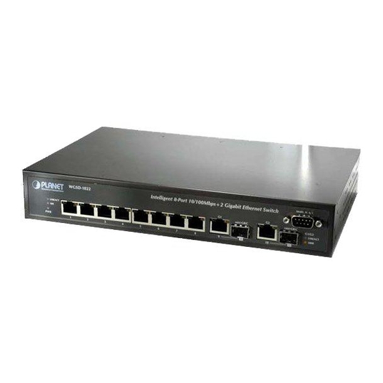
Page 21: Switch Front Panel
38400, N, 8, 1 Intelligent 8-Port 10/100Mbps+2 Gigabit Ethernet Switch LNK/ACT mini-GBIC mini-GBIC G1/G2 LNK/ACT 1000 Figure 2-1 WGSD-1022 front panel. 2.1.3 LED Indications System Color Function Green Lights to indicate that the Switch has power. Per 10/100Mbps port Color... -
Page 22: Install The Switch
The device is a power-required device, it means, it will not work till it is powered. If your networks should active all the time, please consider using UPS (Uninterrupted Power Supply) for your device. It will prevent you from network data loss or network downtime. In some area, installing a surge suppression device may also help to protect your switch from being damaged by unregulated surge or current to the Switch or the power adapter. -
Page 23: Rack Mounting
2.2.2 Rack Mounting To install the switch in a 19-inch standard rack, please follows the instructions described below. Step1: Place the switch on a hard flat surface, with the front panel positioned towards the front side. ep2: Attach the rack-mount bracket to each side of the s witch with supplied screws attached to the package. -
Page 24: Installing The Sfp Transceiver
Figu re 2-7 Plug-in the SFP transceiver Approved PLANET SFP Transceivers PLANET WGSD-1022 support both single mode and multi mode SFP transceiver. The following list of approved PLANET SFP transceivers is correct at the time of publication: SFP (1000BASE-SX SFP transceiver ) ■MGB-SX... - Page 25 Connect the other end of the cable to a device – switches with SFP installed, fiber NIC on a workstation or a Media Converter.. Chec k the LN K/ACT LED of the SFP slot on the front of e Switch. Ensure that the SFP transce iver is op erating...
-
Page 26: Configuration
3. CONFIGURATION This chapter explains the methods that you can use to configure management access to the switch . It describes the types of management applicati ons and the communication and management protocols that deliver data between your management device (work-station or personal computer) and the system. It also c ontains information about port connection options. -
Page 27: Administration Console
‧Most visually appealing ‧May encounter lag times on poor connections ‧Communicates with switch functions at ‧Requires SNMP manager software SNMP ‧Least visually appealing of all three Agent the MIB level ‧Based on open standards methods ‧Some settings require calculations ‧Security can be compromised (hackers need only know the community name) Table 3-1 Management Methods Comparison... -
Page 28: Web Management
No parity 1 stop bit You can change these settings, if desired, after yo u log on. This management method is often preferred because you can remain connected and monitor the system during system reboots. Also, certain error messages are sent to the serial port, regardless of the interface through which the associated action was initiated. -
Page 29: Snmp Protocol
you must have at least one IP address configured on the switch before you can establish access to it with a virtual terminal protocol. Terminal emulation differs from a virtual terminal protocol in that you must connect a Note terminal directly to the console (serial) port. 3.4.2 SNMP Protocol Simple Network Management Protocol (SNMP) is the standard management protocol for multi-vendor IP networks. -
Page 30: Web Configuration
4. Web Configuration The W GSD-1022 can be configured through an Ethernet connection, make sure the manager PC must be se t on same the IP sub net address with the switch. For example, if you have changed the default IP addre ss of the Switch to 192.1 68.1.1 with subnet mask 255.255.255.0 via console, then the manager PC... - Page 31 Figure 4-3 Web Main Screen of WGSD-1022 Now, you can use the Web management interface to continue the switch management or manage the switch by console interface. It is recommended to use Internet Explore 6.0 or above to access WGSD-1022. Note:...
-
Page 32: Main Screen
Description Figure 4-1 Save Config Via the We b-Management, the administrator can setup the WGSD-1022 by select the functions those listed in the Main Function. The screen in Figure 4-2 appears. Figu re 4-2 WGSD-1022 Main Funcrions Menu The follow... -
Page 33: S Etup
SNMP Admin 4.2 S etup The Setup menus include the tree sub-menus: Summary Network Settings Time 4.2.1 Summ The summary screen provides Device and System Information about the Switch. Figure 4-3 System Summary screen The page contains the fol lowing formations: Device Info rmation... -
Page 34: Network Settings
Display the current default gateway setting • Default Gateway Show the IP Address mode of the system – By Static or Dynamic • Address Mode (DHCP) he MAC address of the Switch displays here • Base MAC Address System Information The unique box serial number for this switch •... - Page 35 Figure 4-4 Network Setting screen he page includes the following fields: Iden fication: • Syste Type your system name m Name • System Location Type where the Switch is located • System Contact Enter the administrative contact person • System Object ID Tthe system object identifier is in this field •...
-
Page 36: Time
Enter the IP address when you want to use a static address. • IP Address The default IP Address is 192.168.1.254 Enter the IP subnet mask for the interface. • Subnet Mask The factory default value is 255.255.255.0 Enter the default gateway for the IP interface. •... - Page 37 Local time settings. • Use SNTP Time Specifies that the system time is set via an SNTP server Local Time Defines the system time. The field format is HH:MM:SS, for exam ple, • Hours / Minu ntes / 21:15:03. Seconds Defines the system date.
- Page 38 are: • Date -- The date at which DST ends. The possible field range is 1-31. • Month -- The month of the year in which DST ends. The possible field range is Jan-Dec. • Year-- The year in which the configured DST ends. •...
-
Page 39: Port Configuration
client, and cannot provide time services to other systems. 4.3 Port Configuration In this field, you can see these parts, such as port settings, Link aggregation, LACP. 4.3.1 Port settings To use the port settings screen for setting up each of the switch’s ports. It shows these parts: port, description, admin status, link status, speed, duplex, MDI/MDIX, Flow control, type, LAG, PVE (see Figure 4-6): Figure 4-6 Port Settings screen... - Page 40 Admiinistrator when you choose the Down button • Speed Shows the connection speed of the port and the speed can be configured only when auto-negotiation is disabled on that port • Duplex The port duplex mode, Full (transmission occurs in both directions simultaneously) or Half (transmission occurs in only one direction at a time).
- Page 41 Figure 4-7 Per Port Configuration detail screen The Port Configuration screen contains the following fields: • Port Indicates the number of the port • Description Where can be entered by clicking on the Detail button • Port Type This is the port type •...
- Page 42 • Admin Duplex Change the duplex mode here • Current Duplex Tthis is the duplex mode of the port Mode • Auto Negotiation You can enable or disable the port’s Auto Negotiation feature. If using an SFP module, Auto Negotiation for th e specific port should be set to disable •...
-
Page 43: Link Aggregation
• Current MDI/MDIX This is the current MDI/MDIX status of the port • PVE For Gigabit Eth ernet switches ONLY. When a port is a Private VLAN Edge (PVE) port, it bypasses the Forwarding Database and forwards all unicast, multicast, and broadcast traffic to an upl ink. - Page 44 • Speed Shows th e connection speed of the port and the speed can be configured only when auto-negotiation is disabled on that port • Duplex The port duplex mode, Full (transmission occurs in both directions simultaneously) or Half (transmission occurs in only one direction at a time).
-
Page 45: Lacp
4.3.3 LACP Aggregated Links can be manually setu p or automatically established on the relevant links by enabling Link Aggr egation Co ntrol Protocol (LACP). Aggregat e ports can be linked into link-aggregation port-groups. Each group is comprised of ports with the same speed, set to full-duplex operation. -
Page 46: Vlan Configuration
Layer 2 switch . However, all the network devices are still plug into the same switch physically. The WGSD-1022 supports 802.1Q (tagged-based) and GVRP Dynamic VLAN setting in web manageme nt page. In the def ault configuration, VLAN support is “802.1Q”. -
Page 47: Create Vlan
4.4.1 Create VLAN In this table, the informati on a nd gl obal parameters for configuring and working with VLAN s will be provided (see figure 4-10). Figure 4-10 Create VLAN screen The page contains the following fields: Single VLAN You can configure the ID number of the VLAN by this item. -
Page 48: Port Setting
4.4.2 Port setting In this port setting screen (refer to figure 4-11), the parameters managing ports that are part of a VLAN will be provided, and you ca n set the default VLAN ID (PVID). All untagged packets arriving to the device are tagged by the ports PVID. -
Page 49: Ports To Vlan
pped • Ingress Filtering nables or disables Ingress filtering on the port. Ingress filtering cards packets which do not include an ingress port • LAG Indicates the LAG to which the VLAN is defined Port Mode VLAN Membership Frame Leave Untagged Access Belo... -
Page 50: Vlan To Ports
The page contains the following fi elds: Where means the VLAN number • VLAN Indicates the port belongs to a single untagged VLAN. When a port is • Access Access mode, the packet types which are accepted on the port cannot be designated. -
Page 51: Gvrp
The page contains the following fields: Displays the interface number • Port By which indicates the port to VLAN mode. Possible field values are: • Mode • General - By which indicates the port belongs to VLANs, and each VLAN is user-defined as tagged or untagged (full 802.1Q mode). - Page 52 membership information among V LAN-aware bridges. GVRP allows VLAN-aware bridges to automatic ally learn VLA Ns to bridge ports mapping, without having to individually configure each bridge and register VLAN membership. The Global System LAG informati on displays the same field information as the po rts, but represent the LAG GVRP information.
- Page 53 enabled on the device.. The Update button adds the configured GVRP setting to the table at • Update the bottom of the screen...
-
Page 54: Statistics
4.5 Statistics The Statistic of the switch This field includes these parts as below: 4.5.1 RMON Statisti The RMON Statistics screen (refer to figure 4-16) contains fields for viewing information about device utilization and errors that occurred on the device. Figure 4-16 RMON Statistics screen The page contains the following fi elds:... - Page 55 every 30 seconds. • 60 Sec, which indicates t hat the RMON statistics are refreshed every 60 seconds. • Drop Events which displays the number of dropped events that have occurred on the interface since the device was last refreshed •...
-
Page 56: Rmon History
Refresh Now button, which use this option to refresh the statistics. 4.5.2 RMON History The RMON History contains information about samples of data taken from ports. For example, the samples may include interface definitions or polling periods. The RMON History Control screen is divided into RMON History and Log Table. Log Table includes the following parts (see figure 4-17) igure 4-17 RMON History screen The page contains the following fields:... - Page 57 • Sampling Requested Disp lays the number of samples to be saved. The field range is 1-65 535. The default value is 50 • Current Number of Displays the current number of samples taken. View History button. This button opens the RMON History screen Samples •...
-
Page 58: Rmon Alarm
• Received Packets Displays the number of packets received on the interface since the device was last refreshed, including bad packets, Multicast and Broadcast packets • Broadcast Packets Displays the number of good Broadcast packets received on the interface since the device was last refreshed. This number does not include Multicast packets •... - Page 59 Figure 4-19 RMON Alarm screen The page contains the following fields: • larm Entry Indicates a specific alarm • Source Interface Displays the interface for which RMON statistics are displayed. The possible field values are: • Port, displays the selected port of the RMON statistics. •...
- Page 60 • Rising Event Displays the mechanism in which the alarms are reported. The possible field values are: • LOG. Indicates there is not a saving mechanism for either the device or in the management system. If the device is not reset, the entry remains in the Log Table.
-
Page 61: Rmon Events
4.5.4 RMON Events The RMON Events screen (see figure 4-20) contains fields for defining RMON events. Figure 4-20 RMON Event screen The page contains the following fiel Add Event: • Event Entry isplays the event • Community where displays the community to which the event belongs •... - Page 62 The Event Table area contains th e following additional field: Where displays the time that the event occurred • Time RMON Event Log Press the tton to display the log store in the flash. Only the Event type is L og or Log and Trap, then the entries app ear.
-
Page 63: Port Utilization
4.5.5 Port Utilization The Port Utilization screen (see figure 4-22) indicates the amount of resources each interface is currently consuming. Ports in green are functioning normally, while ports in red are currently transmitting an excessive amount of network traffic. Figure 4-22 Port Utilization screen The page includes the following fields: •... -
Page 64: Statistic
4.5.6 802.1x Statist The 802.1X Statistic screen (see figure 4-23) contains information about EAP packets received on a specific p ort. Figure 4-23 802.1x Statistics screen The page includes the following fields: • Port Indicates the port, which is polled for statistics •... -
Page 65: Gvrp Statistics
4.5.7 GVRP Statistics The GVRP Statistics screen (see figure 4-24) contains device statistics for GVRP. The GVRP Statistics screen is divided into two areas, GVRP Statistics Table and GVRP Error Statistics Table. igure 4-24 GVRP Statistics screen The following fields are relevant for both tables: Specifies the interface type for which the statistics are displayed •... - Page 66 Displays the device GVRP Empty statistics • Empty By which displays the device GVRP Leave Empty statistics • Leave Empty By which displays the device GVRP Join In statistics • Join In By which displays the device GVRP Leave in statistics •...
-
Page 67: Acl
4.6 ACL An ACL consists of a set of rules w hich are matched sequentially against a packet. When a packet meets the match criteria of a rule, the sp ecified rule action (Permit/Deny) is tak en and the additional rules are not check ed for a match . - Page 68 • New ACL Name Defines a new user-defined IP based ACL • Delete ACL By which deletes the selected ACL • Action Indicates the action assigned to the packet matching the ACL. Packets are forwarded or dropped. In addition, the port can be shutdown, a trap can be sent to the network administrator, or a packet assigned rate limiting restrictions for forwarding.
- Page 69 influence the packet filtering process. The TCP Flags that can be selected are: • Urg, indicates the packet is urgent. • Ack, indicates the packet is acknowledged. • Psh, indicates the packet is pushed. • Rst, indicates the connection is dropped. •...
-
Page 70: Mac Based Acl
The possible field range is 0-7 Add to List Use the button when you add the configured IP Based ACLs to the IP Based ACL Table at the bottom of the screen. 4.6.2 MAC Based ACL The MAC Based ACL screen (see figure 4-27) allows a MAC based ACL to be defined. ACEs can be added only if the ACL is not bound to an interface. - Page 71 • Shutdown, where drops packet that meet the ACL criteria, and disables the port to which the packet was addressed. • Source MAC Matches the source MAC address to which packets are addressed to the ACE. Address • Wildcard Mask Defines the source IP address wildca rd mask.
-
Page 72: Security
4.7 Security This section is to control the security access of the switch, includes the user access and management control. The Security function contains links to the following topics: • ACL Binding • RADIUS • TACACS+ • 802.1x Settings • Port Security •... -
Page 73: Radius
Indicates the ACL which is bound to the interface. The selection • ACL Name includes: • IP Based ACL • MAC Based ACL Add to List Use the button to add the ACL Binding configuration to the ACL Binding Table at the bottom of the screen. - Page 74 is the highest value. The RADIUS Server priority is used to configure e server query order • Authentication Port Identifies the authentication port. The authentication port is used to verify the RADIUS server authentication. The authenticated port default is 1812 Defines the number of transmitted requ ests sent to RADIUS server •...
-
Page 75: Tacacs
4.7.3 TACACS+ The device provides Terminal Access Controller Access Control System (TACACS+) client support. TACACS+ provides centralized security for validation of users accessing the device. TACACS+ provides a centralized user management system, while still retaining consistency with RADIUS and other authentication processes. - Page 76 • The T imeout for This displays the amount of time that passes before the connection between the device and the TACACS+ server times out. Reply The field range is 1-30 seconds. • Status Displays the connection status between the device and the TACAC server.
-
Page 77: Settings
4.7.4 802.1x settings Port based authen tication enables authenticating system users on a per-port basis via an external erver. Only authenticated and approved system users can transmit and receive data. Ports are authenticated via the RADIUS server using the Extensible Authentication Protocol (EAP). Refer to figure 4-30. - Page 78 Permits immediate port re-authentication. The Setting Timer button • Enable Periodic opens the Setting Tim er screen to configure ports for 802.1x Re-authentication functionality. Setting T imer On this screen, it includes port, re -authentication, resend ing EAP …. (Refer to figure 4-31) Figu re 4-31 Setting Timer parameter scre The Page contains the following fields:...
-
Page 79: Port Security
4.7.5 Port Security Work security screen (see figure 4-32) can be increased by limiting access on a specific port only to users with specific MAC addresses. MAC addresses can be dynamically learned or statically configured. Locked port security monitors both received and learned packets that are received on specific ports. - Page 80 • Learni ng Mode Where defines the locked port type. The Learning Mode field is enabled only if Locked is selected in the Interface Status field. The possible field values are: • Classic Lock, by which locks the port using the classic lock mechanism.
-
Page 81: Multiple Hosts
4.7.6 Multiple Hosts The Multiple Hosts screen (see figure 4-33) allows network managers to configure advanced port-based authentication settings for specific ports and VLANs. Figure 4-33 M ultiple Hosts screen The Page contains the following fields: • Port Displays the port number for which advanced port-based authentication is enabled. -
Page 82: Storm Control
Frequency (1-1000000) field can be defined only if multiple hosts are disabled. The default is 10 seconds. • Status Where indicates the host status. 4.7.7 Storm control A BroadcastStorm is a result of an excessive amount of broadcast messages simultaneously transmitted across a network by a single port. - Page 83 Multicast, and Broadcast traffic. • Multicast & Broadcast, counts Broadcast and Multicast traffic together. • Broadcast Only, counts only Broadcast traffic. Where the maximum rate (packets per second) at which unknown • Rate Threshold packets are forwarded. The range is 70 -100000. The default value is 3500.
-
Page 84: Qos
4.8 QoS Network traffic is usually unpredictable, and the only basic assurance that can be offered is best effort traffic delivery. To overcome this challenge, Quality of Service (QoS) is applied throughout the network. This ensures that network traffic is prioritized according to specified criteria, and that specific traffic receives preferential treatment. - Page 85 Figure 4-35 CoS Settings screen The Page contains the following fields: This indicates if QoS is enabled on the interface. The possible values • CoS Mode are: • Disable, disables QoS on the interface. • Basic, enables QoS on the interface. •...
-
Page 86: Queue Setting
Default: The Table contain s the following fi elds: Interface to which the CoS configuration applies • Interface Determines the default CoS value for incoming packets for which • Defaul t CoS VLAN tag is not defined. The possible field values are 0- The default CoS is 0 Restores the device factory defaults for mapping CoS values to a •... -
Page 87: Dscp Settings
hich displays the WRR weights to queues • WRR Weight Default Rate 1:2:4:8 Displays the amount of bandwidth assigned to the queue. • % of WRR These values are fixed and are not user- defined. Bandwidth • 6.67% • 13.33% •... -
Page 88: Bandwidth
4.8.4 Bandwidth The Bandwidth screen (refer to figure 4-38) allows network managers to define the bandwidth settings for a specified egress interface. Modifying queue scheduling affects the queue settings globally. The Bandwidth screen is no t used with the Service mode, as bandwidth settings are based on services. Figure 4-38 Bandwidth screen Queue shaping can be based per queue and/or per interface. -
Page 89: Basic Mode
Rate on Selected Port • Committed Defines CIR as the queue shaping type. Information Rate The possible field value is 64 - 1,000,000 Kbps. (CIR) 4.8.5 Basic Mode The Basic Mode screen (see figure 4-39) contains the following fields: Figure 4-39 Basic Mode screen The page contains the following fields: •... -
Page 90: Advanced Mode
4.8.6 Advanced Mod Advance d QoS mode (see figure 4-40) provides rules for specifying flow classification and assigning rule actions that relate to bandwidth m anagement. The rules are based on the Access Control Lists (see Access Control Tab) Figure 4-40 Advance Mode screen AC ACLs and IP ACLs can be grouped together in more complex structures, called policies. - Page 91 Figure 4-41 Out of Profile DSCP Assignments screen The page contains the following fi elds: This displays the D SCP In value. • DSCP In The value is form 0-63. This displays the current DSCP out value. A new value can be •...
- Page 92 Figure 4-42 Policy Settings screen The page contains the following fields: defines a new Policy name • Policy Name this button will add the policy to the Policy Name table • Add to List which selects an existing Policy by name •...
- Page 93 Class Map setting New Class Map, by which the New Class Map button opens the New Class Map screen (see figure 4-33) Figure 4-43 Class Map Settings screen The page contains the following fields: • Class Map Name defines a new Class Map name •...
- Page 94 • MAC ACL Matches packets to MAC based ACLs and to IP based ACLs ggregate Policer, where user-defined aggregate policers. The Aggregate Policer button opens the New Aggregate Policer screen. Aggregate Policer Setting New Aggr egate Policer scree n (se e figure 4-44): Figure 4-44 Aggregate Policer Settings screen The page contains the following fields:...
- Page 95 Action assigned to incoming packets exceeding the CIR. • Exceed Action This field is only relevant when the Police value is Single. Possible values are: • Drop, which drops packets exce eding the defined CIR value. • Remark DSCP, where remarks packet’s DSCP values exceed the defined CIR value.
-
Page 96: Spanning Tree
4.9. S panning T Spanning Tree Protocol (STP) provides tree topography for any arrangement of bridges. STP also provide s one path between end station s on a network, eliminating loops. Loops occur when alternate routes exist between hosts. Loops in an exte nded network can cause bridges to forward traffic indefinitely, resulting in increased traffic and reducing network efficiency. - Page 97 instance ID. Where indicates the port number that offers the lowest cost path from • Root Port this bridge to the Root Bridge. It is significant when the Bridge is not the Root. The default is zero. Where the cost of the path from this bridge to the root. •...
-
Page 98: The Global Stp
4.9.2 The Global The Global STP screen (see figur e 4-46) contains parameters for enabling STP on the device. Global Setting Spanning Tree Stat e, which indicates if STP is enabled on the d evice. Figure 4-46 Global STP screen The page contains the following fields: Global Setting •... -
Page 99: Stp Port Settings
to the selected method. Bridge Settings Specifies the bridge priority value. When switches or bridges are • Priority running STP, each is assigned a priority. After exchanging BPDUs, the device with the lowest priority value becomes the Root B ridge. The port priority value is provided in increm ents of 4096. - Page 100 Figure 4-47 STP Port Settings screen The page contains the following fields: • Interface Indicates the port or LAG on which STP is enabled • STP which indicates if STP is enabled on the port • Port Fast Indicates if Fast Link is enabled on the port. If Fast Link mode is enabled for a port, the Port State is automatically placed in the Forwarding state when the port link is up.
- Page 101 • Speed Indicates the speed at which the port is operating • Path Cost Indic ates the p ort contribution to the root path cost. The path cost is adjusted to a higher or lower value, and is used to forward traffic en a path being rerouted.
-
Page 102: Rstp Port Settings
Figure 4-48 STP Port status screen 4.9.4 RSTP Port set tings While the classic spanning tree prevents Layer 2 forwarding loops in a general network topology, convergence can take between 30-60 seconds. This time may delay detecting possible loops, and pro agating status topol ogy changes. - Page 103 The page contains the following fields: Where displays the port or LAG on which Rapid STP is enabled. • Interface Where indicates the port role assigned by the STP algorithm in order • Role to provide to STP paths. The possible field values are: •...
-
Page 104: Mstp Properties
To estab lish communications over a point-to-point link, t he originating PPP first sends Link Control Protocol (LCP) packets to configure and test the data link. After a Note link is established and optional facilities are negotiated as needed by the LCP, the originating PPP sends Network Control Protocols (NCP) packets to select and nfigure one or more network layer protocols. -
Page 105: Mstp Instance Settings
ich indicates the total number of hops that occur in a specific • Max Hops ion before the BPDU is discarded. Once the BPDU is discarded, the port information is aged out. The possible field range is 1-40. The field default is 20 hops Where identifies the S panning Tree Master instance. - Page 106 MST Inst ance at the VL AN Instat nce Configuration page. The screen in Figure 4-52 appears. Figure 4- 52 MSTP VLAN Instance Configuration screen Defines the VLAN group to which the interface is assigned. • Instance ID Included VLANs re maps the selected VLAN to the selected instance.
-
Page 107: Mstp Interface Settings
Indicates the number of hops remaining to the next destination. • Remaining Hops 4.9.7 MSTP Interfac e Settings Network Administrators can assig n MSTP Interface settings using the MSTP Interface Settin gs screen (see figure 4-53). Figure 4-53 MSTP Interfance Settings screen The MSTP Interface Settings screen contains the following fields: •... - Page 108 • Master Port, where provides connectivity from a MSTP region to the outlying CIST root. • Internal, in dicates the port is an internal port. • Role Indicates the port role assigned by the STP algorithm in order to provide to STP paths. The possible field values are: •...
- Page 109 Figure 4-54 MSTP Interfance configuration screen...
-
Page 110: Multicast
4.10 Multicast The Multicast of the switch On this field, included IGMP Snooping, Bridge Multicast, Forward All… 4.10.1 IGMP Snooping When IGMP Snooping (see figure 4-55) is enabled globally, all IGMP packets are forwarded to the CPU. The CPU analyzes the incoming packets and determines which ports want to join which Multicast groups, which ports have Multicast routers generating IGMP queries, which routing protocols are forwarding packets and Multicast traffic. -
Page 111: Bridge Multicast
Specifies the VLAN ID. • VLAN ID Indicates if IGMP snooping is enabled on the VLAN. • IGMP Status Indicates if Auto L earn is enabled on the device. If Auto Learn is • Auto Learn enabled, the devi ce automatically learns where other Multicast groups are located. - Page 112 Figure 4-56 Bridge Multicast screen The Pag e contains t he following fi elds: Configure Multicast The check box allows to enable Bridge Multicast Filtering function. • Enable Bridge Multicast F iltering This identifies a VLAN to be configured to a Multicast service. •...
- Page 113 Multicast Table Figure 4-57 Bridge Multicast screen Example: Adding Bridge Multicast Addresses Click the check box to enable the Bridge Multicast Filtering. Define the VLAN ID and New Bridge Multicast Address fields. Check a port to Static to join the port to the selected Multicast group. Click “Add to List”...
-
Page 114: Bridge Multicast Forward All
4.10. 3 Bridge Multi ast Forward All The Bridge Multicast Forward All S creen contains fields for attaching ports or LAGs to a device attached to a neighboring Multicast router/switch. Once IGMP Snooping is enabled, Multicast packets are forwarded to the appropriate port or VLAN. Refer to figure 4-58. Figure 4-58 Multicast Bridge Forward All screen The Bridge Multicast Forward All Scree... -
Page 115: Snmp
4.11 SNMP Simple N etwork Managem ent P rotocol (SNMP) provides a method for managing network devices. Devices supporting SNMP run a lo cal software (agent). The SNM P agents maintain a list of variables, which are used to manage the device. The variables ar defined in the Management Informa tion Base ( MIB). -
Page 116: Views
Uses the device generated Engine ID. It’s defined per standard as: • Use Default First 4 octets — first bit = 1, the rest is IANA Enterprise number. To locate the IANA Enterprise number by referring to the Vendor website, or use the show SNMP command using a CLI interface. - Page 117 The page contains the following fields: Indicates the user-defined views. The options are as follows: • View Name • Defau lt - which displays the default SNMP view for read and read/write views. • DefaultSuper - indicates the default SNMP view for administrator views.
-
Page 118: Group Profile
4.11.3 Group Profile The Group Profile screen (see figure 4-61) provides information for creating SNMP groups and ass igning SNMP access control privileges to SNMP groups. Groups allow network managers to assign acces rights to specific device features, or features aspects. ure 4-61 Group Profile screen he page contains the following fields: Displays the user-defined group to which access control rules are... -
Page 119: Group Membership
Defines the group access rights. The possible field values are: • Operation • Read. The management access is restricted to read-only, and changes cannot be made to the assigned SNMP view. • Write. The management access is read-write and changes can be made to the assigned SNMP view. - Page 120 • Remote - Indicates that the user is connected to a remote SNMP entity. If the Engine ID is defined, remote devices receive inform messages Contains a list of user-defined SNMP groups. SNMP groups are • Group Name defined in the SNMP Group Profile page. Indicates the Authentication method used.
-
Page 121: Communities
4.11.5 Communities The Communities screen contains three areas • Communities • Basic Table • Advanced Table he screens in Figure 4-63 and 4-64 sppears Communities Figu re 4-63 Communities configuration screen The page contains the following fields: • SNMP Management Defines the management station IP address for which the advanced SNMP community is defined. - Page 122 options, as well as permissions to modify the community. View Name - contains a list of user-defined SNMP views. • Advanced Enables SNMP Advanced Mode for a selected community and contains the following fields: Group Name - defines advanced SNMP communities group names. Use the button when you want to add the Communities configuration to the respective Table at the bott...
-
Page 123: Notification Filter
Advanced Table Displays the management station IP address for which the basic • Management Station SNMP community is defined. Community String, which displays the password used to authenticate the management station to the device. Displays advanced SNMP communities group name •... -
Page 124: Notification Recipient
Displays the OID for which notifications are sent or blocked. If a filter • New Object is attached to an OID, traps or informs are generated and sent to the Identifier Subtree trap recipients. Object IDs are selected from either the Select from List or the Object ID Li st. - Page 125 Which indicates the IP address to whom the traps are sent. • Recipient IP Defines the notification sent. The possible field values are: • Notification Type Traps, indicates traps are sent. Informs, indicates informs are sent. Enables SNMP v1.2 as the Notification Recipient. Either SNMP v1.2 •...
- Page 126 Figure 4-67 Notification Recipient...
-
Page 127: Admin
4.12 Admin The Admin section provides information for devini ng system parameters including User account and file anagement, device software. Under Admin the folling topics are provided to devine and view the system informatin: User Authentication Static Address Dynamic Address Logging Port Mirroting Cable Test... -
Page 128: Static Address
• Authentication Type Defines the user authentication methods. Also you can choose combinations of all the authentication methods. The possible field values are: • Local, authenticates the user at the device level. The device checks the user name and password for authentication. •... - Page 129 The page contains the following fields: Displays the interface to which the entry refers: • Interface • Port, to which the specific port number the forwarding database parameters refer. • LAG, to which the specific LAG number the forwarding database parameters refer.
-
Page 130: Dynamic Address
4.12 .3 Dynamic Address The Dy namic Address Table contains the MAC addresses learned by monitoring the source address for traf fic entering the switch. When the destination address for inbound traffic is found in the database, the packet s intended for that address are forwarded directly to the associated port. Otherwise, the traffic is flooded to all ports. -
Page 131: Logging
Specifies the interface for which the table is queried. There are two • Port interface types from which to select: • Port - displays the specific port number • LAG - displays the specific LAG number. Specifies the MAC address for which the table is queried •... - Page 132 he page co ntains the following fields: Indicates if device global logs for Cache, File, and Server Logs are • Logging enabled. Console logs are enabled by default. The system is not functioning. • Emerge The system needs immediate attention •...
-
Page 133: Port Mirroring
4.12.5 Port Mirroring Port mirroring monitors and mirrors network traffic by forwarding copies of incoming and outgoing packets from one port to a monitoring port. Port mirroring can be used as diagnostic tool and/or a ebugging fe ature. Por mirroring also enables switch performance monitoring (refer to figure 4-72). Network administrators configure port mirroring by selecting a specific port to copy all packets, and ifferent ports from ch the packets are copied. -
Page 134: Cable Test
.12.6 Cable T The Cable Test screen (see figure 4-73) shows you results from performance tests on copper cables. The maximum cable length that can be tested is 120 meters. Cables are tested when the ports ar e in the own state , except for the Approximate Cable Length test. -
Page 135: Save Configuration
4.12.7 Save Configuration On this screen, you can choose two methods to save the configuration: Via TFTP Upgrade and Via HTTP. ee figur e 4-74 Figure 4-74 Save Configuration via TFTP The page contains the follow ing fields: Via TFTP Select this option to upgrade the switch from a file located on a T •... -
Page 136: Firmware Upgrade
Figure 4-75 Save Configuration via HTTP Select this option to upgrade the switch from a file on the local hard • Upgrade drive. This is used to backup the configuration to the local hard drive. • Back Type in the name and path of the file or Browse to locate the upgrade •... - Page 137 The page contains the following fields: Via TFTP Defines the upgrade through a TFTP Server. • Via TFTP Select file type to be upgraded through a TFTP Server. The possible • File Type field values are : • Softwa re Image •...
-
Page 138: Reboot
4.12.9 Reboot The Reboot screen (see figure 4-78) resets th e device whose configuration is automatically saved before the device is rebooted. Figure 4-78 Reboot screen There is a known issue. Sometimes after the “Reboot” button be pressed, it costs lot Note time to stop the curent tasks. -
Page 139: Server Logs
4.12.11 Server Logs The Global Log Parameters page contains fields for enabling logs globally, and fields for defining log parameters. The Severity log message s are listed from the highest severity to the lowest. Event messages have a unique format, as per the SYSLOG RFC recommended message format for all error reporting. - Page 140 Figure 4-80 Server Logs screen here are five items, as below: Specifies the server to whic h logs can be sent. • Server Defines the UDP port to which the server logs are sent. The possible • UDP Port (1-65535) range is 1 to 65535.
-
Page 141: Memory Logs
4.12.12 Memory Logs he Memory Log screen (see figure 4- 81) contains all system logs in a chronological order that are saved RAM (Cache), Log Index w hich shows the log number, Log Time at which the log was generated, everity which shows the log seve rity, and the description that shows log message text. - Page 142 Figure 4-82 Flash Logs screen...
-
Page 143: Command Structure
5. COMMAND STRUCTURE The WGSD-1022 is a managed Ethernet Switc h that can be controlled by the RS-232 console interface, telnet interface, and W eb interface. This chapter describer how to configure the Switch through these interfaces. hen you are ready to configure the smart functions of th... -
Page 144: Using The Cli
5.2 Using the CLI 5.2.1 CLI Command Modes The Command Line Interface (CLI) syntax, conventions and terminology are described in this sec tion. Each CLI command is illustrated using the structure outlined below. Introduction To assist in configuring devices, the CLI comma nd-line interface is divided into different command modes. -
Page 145: Global Configuration Mode
protected to prevent unauthorized use. The password is not displayed on the screen and is case sensitive. Privileged users are entered directly into the Privileged EXEC mode. To enter the Privileged EXEC mode commands from the User EXEC mode p erform the following: At the prompt enter the command enable and press <E nter>. - Page 146 ret rn from Global Configuration mode to Privileged EXEC mode, the user can use one of the followin g commands: exit Ctrl+Z The following example illustrates ho w to access Global Configuration mode and teturn back to the Privileged EXEC mode: console # console # configure console(config) # exit...
-
Page 147: Starting The Cli
Configuration mode command interface port-channel is used to enter the port-channel Interf Configuration mode. SSH Public Key-chain—Contains commands to manually specify other device SSH public keys. The Global Configuration mode command crypto key pubkey-ch ain ssh is used to enter the SSH Public Key-chain Configur ation mode. -
Page 148: Editing Features
5.2.3 Editing Features Entering Commands A CLI command is a series of keywords and arguments. Keywords identify a command, and arguments specify configuration parameters. For example, in the command "show interfaces status ethernet e5 ," show, in terfaces and status are keywords, ethernet is an argument that specifies the interface type, and e5 specifies the port. - Page 149 Keyword Source or destination Up-arrow key Recalls command s in the history buffer, beginning with the most recent command. Ctrl+P Repeats the key sequence to recall successively older comm ands. Down-arrow Returns to more recent commands in the history buffer after recalling commands with the up-arrow key.
-
Page 150: Keyboard Shortcuts
Keyboard Shortcuts The CLI has a range of keyboard shortcuts to assist in editing the CLI commands. The following table describes the CLI shortcuts. Keyboard Key Description Up-arrow key Recalls commands in the history buffer, beginning with the most recent command. -
Page 151: Aaa Commands
Ctrl+F4 Any combination keys pressed simultaneously on the keyboard. Screen Indicates system messages and prompts appearing on the console. Displ When a parameter is required to define a range of ports or parameters and all is an option, the default for the command is all when no parameters are defined. For e xample, the command interface range port-channel has the option of eithe... -
Page 152: Aaa Authentication Enable
radius Uses the list of all RADIUS servers for authentication. Uses username tacacs Uses the list of all TACACS servers for authentication. Uses username Default Configuration The local us er database is checked. This has the same effect as the command aaa authentication login listname local. -
Page 153: Default Configuration
methods,when using higher privilege levels. list-name — Character string used to name the list of authentication methods activated, when using accesshigher privilege levels. method1 [method2...]—Specify at least on e from the following table: Keyword Source or destination Enable Uses the enable password for authentication. Line Uses the line password for authentication None... -
Page 154: Login Authentication
Example The following example sets authentication when accessing higher privilege levels. console (config) # aaa authentication enable default enable 5.3.3 login authentication he login authentication line configuration c ommand specifies the login authentication method list for a emote telnet or console . -
Page 155: Ip Http Authentication
yntax nable authentication {default | list-name} n enable authentication default — Uses the default list created with the authentication enable comm and. list-name — Uses the indicated list created with the authentication enable co mmand. efault Configuration ses the default set with the command authentication enable. Comman d Mode e Configuration mode... -
Page 156: Ip Https Authentication
tacacs Uses the list of all TACACS servers for authentication Default Configuration The local use r database is checked. This has the same effect as the command ip http authentication local. mmand Mode Global Confi guration mode Us r e Guidelines The d a ditional methods of authentication are used only if the previous method returns an error, not if it fails. -
Page 157: Show Authentication Methods
efault Configuration he local user database is checked. This has the sa me effect as the command ip https authentication ocal. ommand Mode Global Configuration mode User Guidelines The additional methods of authentication are used only if the previous method returns an error, not if it fails. -
Page 158: Password
Console_Login: Line, None Enable Authentication Method Lists ----------------------------------- Default: Radius, Enable Console_Enable: Enable, None Login Method Li Enable Method List ---- ------------------ ---------------------- ------------------ ----------------------------------- Cons Console_Login nsole_Enable Te et Default efault Default Default HTTP: Radius, local HTTPS: Radius, local 802.1x: Radius 5.3.8 password The password line configuration command specifies a password on a line. -
Page 159: Enable Password
5.3.9 enable password The enable password global configuration command sets a local password to control access to normal and privilege levels. To remove the password requirement, use the no form of this command. Syntax enable passw ord [level level] password [encrypted] no enable password [level level] password —... -
Page 160: Show Users Accounts
Command Mode Global Configuration mode User Guidelines Up to 30 users can be d efined on the device. Example The following example configures user "bob" with the password "lee" and user level 15 to the system. console (config)# username bob password lee level 15 .3.11 show users accounts The show users accounts privilege d EXEC command displays information about the local user... -
Page 161: Address Table Commands
5.4 Address Table Commands 5.4.1 bridge address The bridge address VLAN interface con figuration command adds a static MAC-layer station source address to the bridge table. To delete the MAC address, use the no form of the bridge address command (us ing the no form of the command without specifying a MAC address deletes all static MAC addresses belonging to this VLAN). -
Page 162: Bridge Multicast Filtering
5.4.2 bridge multicast filtering The bridge multicast filtering global configuration command enables filtering of multicast addresses . To disable filtering of multicast addresses, use the no form of the bridge multicast filtering command. Syntax bridge multic ast filtering no b ridge multicast filtering Default Configuration Disab... -
Page 163: Bridge Multicast Forbidden Address
interface-list — Separate nonconsecutive Ethernet ports with a comma and no spaces; a hyphen is used to designate a range of ports. port-channel-number -list — Separate nonconsecutive port-channels with a comma and no spaces; a hyphen is used to desi gnate a range of ports. -
Page 164: Bridge Multicast Forward-Unregistered
interface-list — Separate non consecutive valid Ethernet ports with a comma and no spaces; hyphen is used to designate a range of ports. port-channel-number-list — Separate non consecutive valid port-channels with a comma and no spaces; a hyphen is used to designa te a range of port-channels. -
Page 165: Bridge Multicast Forbidden Forward-Unregistered
Command Modes Interface configuration (VLA N) mode User Guidelines If routers exist on the VLAN, do not change the u nregistered multicast addresses state to drop on the routers ports. Examp his example enables forwarding unregistered multicast ad dresses within VLAN 8. console (config)# interface vlan 8 console (config-if)# bridge multicast forward-unregistered add ethernet 1- 9 5.4.6... -
Page 166: Bridge Multicast Forward-All
Examples This example forbids port 1 to be a Forwarding-unregistered-multicast-addresses port within VLAN 8. console (config)# interface vlan 8 console (config-if)# bridge multicast forward-unregistered add ethernet 1 5.4.7 bridge multicast forwa rd-all The bridge multicast forward-all inte rface configuration command enables forwarding of all multicast packets on a port. -
Page 167: Bridge Multicast Forbidden Forward-All
5.4.8 bridge multicast forbidden forward-all The bridge multicast forbidden forward-all interface configuration command forbids a port to be a forward-allmulticast port. To restore the default, use the no form of the bridge multicast forward-all command. Syntax bridge multicast forbidden forward-all {add | remove} {ethernet interface-list | port-channel port-channel-number-list} o bridge multicast forward-all add —... -
Page 168: Clear Bridge
Syntax bridge aging-time seconds no bridge aging-time seconds — Time is number of seconds. (Range: 10 - 630 seconds) Default Configuration 300 seconds Command Mode Global Configuration mode User Guidelines There are no user guidelines for this c ommand. xample In this example the bridge aging time is set to 250. -
Page 169: Port Security
5.4.11 port security port security interface configuration command locks the port. By locking the port, new ad dresses are not le arned on the port. To enable new address learning, use the no form of the port security command. Syntax port security [forward | discard | discard-shutdown] [trap seconds] no port security forward —... -
Page 170: Show Bridge Address-Table
Syntax port security routed secure-address mac-address no port security routed se cure-address mac-address mac-address — Specify a MAC address. Default Co nfiguration No addresses are defined. Comman d Mode Interface configuration (Ethernet, port-channel). Cannot be configured for a range of interfaces (range context). -
Page 171: Show Bridge Address-Table Static
Command Mode rivileged EXEC mode User Guidelines There are no user guidelines for this command. xample n this example, all classes of entries in the bridge-forwa rding database are displayed. console# show bridge address-table Aging time is 250 sec vlan mac address port type... -
Page 172: Show Bridge Address-Table Count
console# show bridge address-table static Aging time is 300 sec vlan mac address port type ------ -------------------- ------ ------- 0060.704C.73FF permanent 0060.708C.73FF delete-on-timeout 0010.0D48.37FF delete-on-reset 5.4.15 show bridge address-table count show bridge address-t able count privileged EXEC command displays the number of addresses present in all VLANs or at a specific VLAN. -
Page 173: Show Bridge Multicast Address-Table
5.4.16 show bridge multicast address-table he show bridg multicast address-table privileged EXEC command d isplays multicast MAC address table information. Syntax show bridge mult icast address-table [vlan vlan-id] [address mac-multicast-address | ip-multicast-addres s] [format ip | mac] vlan_id — A VLAN ID value. -
Page 174: Show Bridge Multicast Filtering
Vlan IP Address Ports ------ --------------- ---------- 224-239.130|2.2.3 224-239.130|2.2.8 5.4.17 show bridge multicast filtering The show bridge multicast filtering privileged EXEC command di splays the multicast filtering configuration. Syntax show bridge multicast filtering vlan-id vlan_id — A valid VLAN ID value. Default Configuration This command has no default configuration. -
Page 175: Show Ports Security
5.4.18 show ports security The show ports security privileged EXEC command displays the port-lock status. Syntax show ports security [ethernet interface | port-channel port-channel-number] interface — A valid Ethernet port. port-channel-number — A valid port-channel number. Default Configuration This command has no default configuration. Command Mode Privileged EXEC mode User Guidelines... -
Page 176: Clock Commands
.5 Clock Commands 5.5.1 clock set The clock set privileged EXEC command manually sets the system clock. yntax lock set h h:mm:ss day month year lock set hh:mm:ss month day year hh:mm:ss — Current time in h ours (military format), minutes, and seconds (0 - 23, mm: 0 - 59, ss: 0 - 59). -
Page 177: Clock Timezone
Default Configuration o external clock so urce ommand Mod rivileged EXEC mode User Guidelines There are no user guidelines for this command. xamples he following example configures an external time source for the system clock. console# clock source sntp 5.5.3 clock timezone The clock timezone global configuration command sets the time zone for display purposes. -
Page 178: Clock Summer-Time
5.5.4 clock summer-time The clock summer-time global configuration command configures the system to automatically switch to summer time (daylight saving time),. To co nfigure the software to not automatically switch to summer time, use the no form of this command. Syntax clock summe r-time recurring {usa | eu | {week day month hh:mm week day month hh:mm}} [offset... -
Page 179: Sntp Authentication-Key
User Guidelines In both the date and recurring forms of the command, the first part of the command specifies when summer time begins, and the second part specifies when it ends. All times are relative to the local time zone. The start time is relativ e to standard time. -
Page 180: Sntp Authenticate
Command Mode Global Configuration mode ser Guidelines here are no user guidelines for this command. xamples The following example defines the authentication key for SNTP. cnsole(config)# sntp authentication-key 8 md5 ClkKey console(config)# sntp trusted-key 8 console(config)# sntp authenticate 5.6 sntp authenticate The sntp authenticate global configuration command grants authentication for received Network Time Protocol (NTP) traffic from servers,. -
Page 181: Sntp Trusted-Key
5.7 sntp trusted-key sntp trusted-key global configuration com mand authenticates the identity of a system to which Sim e pl Network Time Protocol (SNTP) will synchro nize. To disable authentication of the identity of the system, use the no form of this command. Syntax sntp trusted-key key-number no sntp trusted-key key-number... -
Page 182: Sntp Broadcast Client Enable
Command Mode Global configuration mode User Guidelines There are no user guidelines for this command. Examples The following example sets the polling time for the Simple Network Time Protocol (SNTP) client to 120 econds. Console(config)# sntp client poll timer 120 5.5.9 sntp broadcast client enable The sntp broadcast client enable global configuration command enables the Simple Network Time Protocol... -
Page 183: Sntp Anycast Client Enable
5.5.10 sntp anycast client enable The sntp anycast client enable global configuration command enables anycast client. To disable the polling for SNTP broadcast client, use the no form of th is command. Syntax sntp anycast client enable no sntp anycast clien t enable s c mmand has no arguments or keywords. -
Page 184: Sntp Unicast Client Enable
User Guidelines Use the sntp clien t enable global configuration command to enable broadcast clients globally. Use the sn tp anycast client enable global configuration command to enable anycast clients globally. Examples The ol f lowing example enable s the SNTP client on the interface. console (config)# sntp client enable 5.5.12 sntp unicast client enable The sntp unicast client enab... -
Page 185: Sntp Unicast Client Poll
5.5.13 sntp unicast client poll The sntp unicast client poll global configuration comm and enables polling for the Simple Network Time Protocol (SNTP) predefined unicast clients. To disable the polling for SNTP client, use the no form of this command. Syntax sntp unicast client poll no sntp unicast client poll... -
Page 186: Show Clock
ip-address — IP address of the server. An out-of-band IP address can be specified as described in the usage guidelines hostname — Hostname of the se rver. (Range: 1 - 160 characters) poll — Enable polling. key keyed — Authentication ke y to use when sending packets to this peer. -
Page 187: Show Sntp Configuration
Command Mode User EXEC mode User Guidelines There are no user guidelines for this command. Example The following example displays the time and date from the system clock. Console# show clock 15:29:03 Jun 17 2005 5.5.16 show sntp configuration The show sntp configuration Privileged EXEC command shows the configuration of the Simple Network Time Protocol (SNTP), use Syntax show sntp configuration... -
Page 188: Show Sntp Status
Unicast Clients Polling: Enabled. Server Polling Encryption Key ----------- ----------- ---------------------- 176.1.1.8 Enabled 176.1.8.179 Disabled Disabled Broadcast Clients: Enabled Broadcast Clients Poll: Enabled Broadcast Interfaces: 1/1, 1/3 OOB SNTP servers Server Polling Encryption Key ----------- ------------ ---------------------- 10.1.1.91 Enabled Broadcast Clients: Enabled Broadcast Clients Poll: Enabled Broadcast Interfaces: 1/1, 1/3 5.5.17 show sntp status... -
Page 189: Configuration And Image Files
Console# show sntp status Clock is synchronized, stratum 4, reference is 176.1.1.8 Reference time is AFE2525E.70597B34 (00:10:22.438 PDT Jul 5 1993) Unicast servers: Server Preference Status Last response Offset Delay [mSec] [mSec] ----------- ----------------- ----------- ---------------------- ----------- ------------ 176.1.1.8 Primary AFE252C1.6DBDDFF2 7.33 117.79... -
Page 190: Command Mode
startup-config Represents the startup configuration file. backup-config Represents the backup configuration file. Image The image is executable code which is decompressed during system startup, into the switching and routing software that manages the device. There are always two images stored in the device flash known as "image-1" and "image-2". The images do not necessarily have to contain the same versions of the software. - Page 191 File download from a TFTP server may take a long time, and therefore fail, if there are many Quality of Service elements (ACLs, policers, etc.) present. In this case, it is recommended to copy the TFTP file to the backup configuration file, and then copy the backup file to the running / startup configuration file. When using tftp to copy files, it is recommended to set the tftp server timeout to 10-20 second.
- Page 192 Use the copy source-url boot command to copy a boot file from a server to Flash memory. Copying a Configuration File from a Server to the Running Configuration Use the copy source-url running-config command to load a "configuration file" from a network server to the device "running configuration".
-
Page 193: Show Startup-Config
Accessing file 'file1' on 172.16.101.101... Loading file1 from 172.16.101.101: !!!!!!!!!!!!!!!!!!!!!!!!!!!!!!!!!!!!!!!!!!!!!!!!!!!!!!!!!!!!! !!!!!!!!!!!!!!!!!!!!!!!!!!!!!!!!!!!!!!!!!!!!!!!!!!!!!!!!!!!!!!!!!!!!!!!!!! !!!!!!!!!!!!!!!!!!!!!!!!!!!!!!!!!!!!!!!!!!!!!!!!!!!!!!!!!!!!!!!!!!!!!!!!!! !!!!! [OK] Copy took 0:01:11 [hh:mm:ss] Accessing file 'configfile' on oob/172.16.1.1... Loading file1 from oob/172.16.1.1: !!!!!!!!!!!!!!!!!!!!!!!!!!!!!!!!!!!!!!!!!!!!!!!!!!!!!!!!!!!!! !!!!!!!!!!!!!!!!!!!!!!!!!!!!!!!!!!!!!!!!!!!!!!!!!!!!!!!!!!!!!!!!!!!!!!!!!! !!!!!!!!!!!!!!!!!!!!!!!!!!!!!!!!!!!!!!!!!!!!!!!!!!!!!!!!!!!!!!!!!!!!!!!!!! !!!!! [OK] Copy took 0:0:23 [hh:mm:ss] 5.6.4 show startup-config The show startup-config privileged EXEC command displays the startup configuration file contents. Syntax show startup-config Default Configuration... - Page 194 software version 1.1 hostname device interface ethernet 1/1 ip address 176.242.100.100 255.255.255.0 duplex full speed 1000 interface ethernet 1/2 ip address 176.243.100.100 255.255.255.0 duplex full speed 1000...
-
Page 195: Ethernet Configuration Commands
5.7 Ethernet Configuration Commands 5.7.1 interface ethernet The interface ethernet global configuration command enters the interface configuration mode to configure an Ethernet type interface. Syntax interface ethernet interface interface — Valid Ethernet port. Default Configuration This command has no default configuration. Command Mode Global Configuration mode User Guidelines... -
Page 196: Shutdown
Command Mode Global Configuration mode User Guidelines Commands under the interface range context are executed independently on each active interface in the range. If the command returns an error on one of the active interfaces, it does not stop executing commands on other active interfaces. -
Page 197: Description
The following example re-enables Ethernet port e5. Console(config)# interface ethernet e5 Console(config-if)# no shutdown 5.7.4 description The description interface configuration command adds a description to an interface. To remove the description use the no form of this command. Syntax description string no description string—Comment or a description of the port up to 64 characters. -
Page 198: Duplex
10—Configures the port to 10 Mbps. 100—Configures the port to 100 Mbps. 1000—Configures the port to 1000 Mbps. Default Configuration Maximum port capability. Command Mode Interface Configuration (Ethernet, port-channel, out-of-band Ethernet) mode User Guidelines The command "no speed" in port-channel context returns each port in the port-channel to its maximum capability. -
Page 199: Negotiation
User Guidelines Before attempting to force a particular duplex mode on the port operating at 10/100 Mbps, disable the auto-negotiation on that port. Half duplex mode can be set only for ports operating at 10 Mbps or 100 Mbps. Example The following example configures the duplex operation of Ethernet e5 to force full duplex operation. -
Page 200: Flowcontrol
5.7.8 flowcontrol The flowcontrol interface configuration command configures the Flow Control on a given interface. To restore the default, use the no form of this command. Syntax flowcontrol {auto | on | off | rx | tx} no flowcontrol auto—Enables auto-negotiation of Flow Control. on—Enables Flow Control. -
Page 201: Back-Pressure
Syntax mdix {on | auto} no mdix on—Manual mdix auto—Auto mdi/mdix Default Configuration Automatic crossover is enabled Command Mode Interface Configuration (Ethernet) mode User Guidelines Mdix Auto : All possibilities to connect a PC with cross OR normal cables are supported and are automatically detected. -
Page 202: Port Jumbo-Frame
Command Mode Interface Configuration (Ethernet, port-channel) mode User Guidelines Back Pressure will operate only if duplex mode is set to half. Example In the following example Back Pressure is enabled on e5. Console(config)# interface ethernet e5 Console(config-if)# back-pressure 5.7.11 port jumbo-frame The port jumbo-frame global configuration command enables jumbo frames for the device. -
Page 203: Set Interface Active
Syntax clear counters [ethernet interface | port-channel port-channel-number] Interface — Valid Ethernet port. port-channel-number — Valid port-channel trunk index. Default Configuration This command has no default configuration. Command Mode User EXEC mode User Guidelines There are no user guidelines for this command. Example In the following example, the counters for interface g1 are cleared. -
Page 204: Show Interfaces Configuration
console# set interface active ethernet e5 5.7.14 show interfaces configuration The show interfaces configuration Privilege EXEC mode command displays the configuration for all configured interfaces. Syntax show interfaces configuration [ethernet interface | port-channel port-channel-number | ] Interface — Valid Ethernet port. port-channel-number —... -
Page 205: Show Interfaces Status
Enabled Off Enabled Off Enabled Off Enabled Off Enabled Off Enabled Off The displayed port configuration information includes the following: Port—The port number. Port Type—The port designated IEEE shorthand identifier. For example 1000Base-T refers to 1000 Mbps baseband signaling inluding both Tx and Rx transmissions. Duplex—Displays the port Duplex status. -
Page 206: Show Interfaces Description
User Guidelines There are no user guidelines for this command. Example The following example displays the status for all configured interfaces. Console# show interfaces status Port Type Duplex Speed Flow Link Back Mdix Control State Pressure Mode ----- -------- ------------ ----------- ------------ ----------- ---------- ------------ -----------... -
Page 207: Show Interfaces Counters
Interface — Valid Ethernet port. port-channel-number — A valid port-channel trunk index. oob-interface — Out-of-band Ethernet port number. Default Configuration This command has no default configuration. Command Modes Privilege EXEC mode User Guidelines There are no user guidelines for this command. Example The following example displays the description for the interface g1. -
Page 208: Command Modes
Default Configuration This command has no default configuration. Command Modes Privilege EXEC mode User Guidelines There are no user guidelines for this command. Examples The following example displays traffic seen by the physical interface: Console# show interfaces counters Port InOctets InUcastPkts InMcastPkts InBcastPkts... - Page 209 Console# show interfaces counters ethernet g1 Port OutOctets OutUcastPkts OutMcastPkts OutBcastPkts ------ ------------- ------------------- ------------------- ------------------ 183892 1289 Port OutOctets OutUcastPkts OutMcastPkts OutBcastPkts ------ ------------- ------------------- ------------------- ------------------ 9188 FCS Errors: 8 Single Collision Frames: 0 Multiple Collision Frames: 0 SQE Test Errors: 0 Deferred Transmissions: 0 Late Collisions: 0...
-
Page 210: Show Ports Jumbo-Frame
OutBcastPkts Counted transmitted broadcast packets. FCS Errors Counted frames received that are an integral number of octets in length but do not pass the FCS check. Single Collision Counted frames that are involved in a single collision, and are subsequently Frames transmitted successfully. -
Page 211: Port Storm-Control Broadcast Enable
Console# show ports jumbo-frame Jumbo frames are disabled Jumbo frames will be enabled after reset 5.7.20 port storm-control broadcast enable The port storm-control broadcast enable interface configuration command enables broadcast storm control. To disable broadcast storm control, use the no form of this command. Syntax port storm-control broadcast enable no port storm-control broadcast enable... -
Page 212: Show Ports Storm-Control
port storm-control broadcast rate rate no port storm-control broadcast rate rate—Maximum of kilobytes per second of broadcast and multicast traffic on a port. (Rate: 70 - 100000) Default Configuration The default storm control broadcast rate is 12000. Command Mode Interface Configuration (Ethernet) User Guidelines Use the port storm-control broadcast enable interface configuration command to enable broadcast storm control. -
Page 213: Gvrp Commands
User Guidelines There are no user guidelines for this command. Example The following example displays the storm control configuration. Console# show ports storm-control Port Broadcast Storm control [kbyes/sec] ----- ------------------------------------------------- 8000 Disabled Disabled 5.8 GVRP Commands 5.8.1 gvrp enable (global) GVRP, or GARP VLAN Registration Protocol, is an industry-standard protocol designed to propagate VLAN information from device to device. -
Page 214: Gvrp Enable (Interface)
Example The following example globally enables GVRP on the device. Console (config)# gvrp enable 5.8.2 gvrp enable (interface) The gvrp enable interface configuration command enables GVRP on an interface. To disable GVRP on an interface, use the no form of this command. Syntax gvrp enable no gvrp enable... -
Page 215: Gvrp Vlan-Creation-Forbid
GARP state. The Leave Time is activated by a Leave All Time message sent/received, and cancelled by the Join message. (Range: 10-2147483640) leaveall — Used to confirm the port within the VLAN. The time in milliseconds between messages sent. (Range: 10-2147483640) timer_value —... -
Page 216: Gvrp Registration-Forbid
Syntax gvrp vlan-creation-forbid no gvrp vlan-creation-forbid Default Configuration By default, dynamic VLAN creation is enabled. Command Mode Interface Configuration (Ethernet, port-channel) mode User Guidelines This command forbids dynamic VLAN creation from the interface. The creation or modification of dynamic VLAN registration entries as a result of the GVRP exchanges on an interface are restricted only to those VLANs for which static VLAN registration exists. -
Page 217: Clear Gvrp Statistics
Example The following example shows how default dynamic registering and deregistering is forbidden for each VLAN on port e8. Console (config)# interface ethernet e8 Console (config-if)# gvrp registration-forbid 5.8.7 clear gvrp statistics The clear gvrp statistics privileged EXEC command clears all the GVRP statistics information. Syntax clear gvrp statistics [ethernet interface | port-channel port-channel-number] •... -
Page 218: Show Gvrp Statistics
Default Configuration This command has no default configuration. Command Mode User EXEC mode User Guidelines There are no user guidelines for this command. Example The following example shows how to display GVRP configuration information: Console# show gvrp configuration GVRP Feature is currently enabled on the switch. Maximum VLANs: 255, Port(s) GVRP... -
Page 219: Show Gvrp Error-Statistics
User Guidelines There are no user guidelines for this command. Example The following example shows GVRP statistics information: Console# show gvrp statistics GVRP statistics: ----------------------- rJE : Join Empty Received rJIn : Join In Received rEmp : Empty Received rLIn : Leave In Received rLE : Leave Empty Received rLA : Leave All Received sJE : Join Empty Sent... -
Page 220: Igmp Snooping Commands
Command Mode User EXEC mode User Guidelines There are no user guidelines for this command. Example The following example displays GVRP statistics information. Console# show gvrp-error statistics GVRP error statistics: ----------------------------- Legend: INVPROT : Invalid Protocol Id INVPLEN : Invalid PDU Length INVATYP : Invalid Attribute Type INVALEN : Invalid Attribute Length INVAVAL : Invalid Attribute Value... -
Page 221: Ip Igmp Snooping (Interface)
Default Configuration IGMP snooping is disabled. Command Mode Global Configuration mode User Guidelines There are no user guidelines for this command. Example The following example enables IGMP snooping. Console (config)# ip igmp snooping 5.9.2 ip igmp snooping (Interface) The ip igmp snooping interface configuration command enables Internet Group Management Protocol (IGMP) snooping on a specific VLAN. -
Page 222: Ip Igmp Snooping Mrouter
5.9.3 ip igmp snooping mrouter The ip igmp snooping mrouter interface configuration command enables automatic learning of multicast router ports in the context of a specific VLAN. To remove automatic learning of multicast router ports, use the no form of this command. Syntax ip igmp snooping mrouter learn-pim-dvmrp no ip igmp snooping mrouter learn-pim-dvmrp... -
Page 223: Ip Igmp Snooping Mrouter-Time-Out
User Guidelines The timeout should be at least greater than 2*query_interval+max_response_time of the IGMP router. Example The following example configures the host timeout to 300 seconds. Console (config)# interface vlan 2 Console (config-if)# ip igmp snooping host-time-out 300 5.9.5 ip igmp snooping mrouter-time-out The ip igmp snooping mrouter-time-out interface configuration command configures the mrouter-time-out. -
Page 224: Ip Igmp Snooping Leave-Time-Out
5.9.6 ip igmp snooping leave-time-out The ip igmp snooping leave-time-out command configures the leave-time-out. If an IGMP report for a multicast group is not received within the leave-time-out period after an IGMP leave was received from a specific port, the current port is deleted from the member list of that multicast group. To configure the default leave-time-out, use the no form of this command. -
Page 225: Show Ip Igmp Snooping Interface
Default Configuration This command has no default configuration. Command Mode User EXEC mode User Guidelines There are no user guidelines for this command. Example The following example shows IGMP snooping mrouter information. Console # show ip igmp snooping mrouter VLAN Ports --------- -----------... -
Page 226: Show Ip Igmp Snooping Groups
IGMP Snooping is disabled on VLAN 1 IGMP host timeout is 260 sec IGMP Immediate leave is disabled. IGMP leave timeout is 60 sec IGMP mrouter timeout is 300 sec Automatic learning of multicast router ports is enabled 5.9.9 show ip igmp snooping groups The show ip igmp snooping groups user EXEC command displays the multicast groups learned by IGMP snooping. -
Page 227: Ip Addressing Commands
5.10 IP Addressing Commands 5.10.1 ip address The ip address interface configuration command sets an IP address. To remove an IP address, use the no form of this command. Syntax ip address ip-address {mask | prefix-length} no ip address [ip-address] ip-address —... - Page 228 Syntax ip address dhcp [hostname host-name] no ip address dhcp hostname — Specifies the host name. host-name — DHCP host name. This name need not be the same as the host name entered in global configuration mode. Default Configuration This command has no default configuration. Command Mode Interface configuration (Ethernet, VLAN, port-channel, out-of-band Ethernet) User Guidelines...
-
Page 229: Ip Default-Gateway
Console (config-if)# ip address dhcp 5.10.3 ip default-gateway The ip default-gateway command defines a default gateway (router). To remove the default gateway use the no form of this command. Syntax ip default-gateway ip-address no ip default-gateway ip-address — Valid IP address that specifies the IP address of the default gateway. Default Configuration No default gateway is defined. -
Page 230: Arp
Default Configuration This command has no default configuration. Command Mode User EXEC mode User Guidelines There are no user guidelines for this command. Example The following example displays VLAN 1 configuration. Console# show ip interface vlan 1 5.10.5 arp The arp global configuration command adds a permanent entry in the Address Resolution Protocol (ARP) cache. -
Page 231: Arp Timeout
Example The following example adds the IP address 198.133.219.232 and MAC address 00-00-0c-40-0f-bc to the ARP table. Console (config)# arp 198.133.219.232 0000.0c40.0fbc ethernet e8 5.10.6 arp timeout The arp timeout global configuration command configures how long an entry remains in the ARP cache. To restore the default value, use the no form of this command. -
Page 232: Clear Arp-Cache
5.10.7 clear arp-cache The clear arp-cache privileged EXEC command deletes all dynamic entries from the ARP cache. Syntax clear arp-cache Default Configuration This command has no default configuration. Command Mode Privileged EXEC mode User Guidelines There are no user guidelines for this command. Example The following example deletes all dynamic entries from the ARP cache. -
Page 233: Lacp Commands
Interface IP address HW address status ------------ ------------------------ ------------------ -------- 10.7.1.102 00:10:B5:04:DB:4B Dynamic 10.7.1.135 00:50:22:00:2A:A4 Static 5.11 LACP Commands 5.11.1 lacp system-priority The lacp system-priority global configuration command configures the system priority. To reset to default, use the no form of this command. Syntax lacp system-priority value no lacp system-priority... -
Page 234: Lacp Port-Priority
5.11.2 lacp port-priority The lacp port-priority interface configuration command configures the priority value for physical ports. To reset to default priority value, use the no form of this command. Syntax lacp port-priority value no lacp port-priority value — Port priority value. (Range: 1 - 65535) Default Configuration The default port priority value is 1. -
Page 235: Show Lacp Ethernet
Command Mode Interface Configuration (Ethernet) mode User Guidelines There are no user guidelines for this command. Example The following example assigns an administrative LACP timeout for port e8 to a long timeout value. Console (config)# interface ethernet e8 Console (config-if)# lacp timeout long 5.11.4 show lacp ethernet The show lacp ethernet privilege EXEC command displays LACP information for Ethernet ports. -
Page 236: Show Lacp Port-Channel
5.11.5 show lacp port-channel The show lacp port-channel privileged EXEC command displays LACP information for a port-channel. Syntax show lacp port-channel [port_channel_number] port_channel_number — The port-channel number. Default Configuration This command has no default configuration. Command Mode Privileged EXEC mode User Guidelines There are no user guidelines for this command. -
Page 237: Speed
Syntax line {console | telnet | ssh} console — Console terminal line. telnet — Virtual terminal for remote console access (Telnet). ssh — Virtual terminal for secured remote console access (SSH). Default Configuration This command has no default configuration. Command Mode Global Configuration mode User Guidelines There are no user guidelines for this command. -
Page 238: Exec-Timeout
Console (config)# line console Console(config-line)# speed 19200 5.12.3 exec-timeout The exec-timeout line configuration command sets the interval that the system waits until user input is detected. To restore the default setting, use the no form of this command. Syntax exec-timeout minutes [seconds] no exec-timeout minutes —... - Page 239 telnet — Virtual terminal for remote console access (Telnet). ssh — Virtual terminal for secured remote console access (SSH). Default Configuration This command has no default configuration. Command Mode User EXEC mode User Guidelines There are no user guidelines for this command. Examples The following example displays the line configuration.
-
Page 240: Management Acl Commands
5.13 Management ACL Commands 5.13.1 management access-list The management access-list configuration command defines an access-list for management, and enters the access-list for configuration. Once in the access-list configuration mode, the denied or permitted access conditions are configured with the deny and permit commands. To remove an access list, use the no form of this command. -
Page 241: Permit (Management)
Console (config)# management access-list mlist Console (config-macl)# deny ethernet g1 Console (config-macl)# deny ethernet g2 Console (config-macl)# permit Console (config-macl)# exit Console (config)# management access-class mlist 5.13.2 permit (management) The permit management access-list configuration command defines a permit rule. Syntax permit [ethernet interface-number | vlan vlan-id | port-channel number | out-of-band-eth oob-interface] [service service] permit ip-source ip-address [mask mask | prefix-length] [ethernet interface-number | vlan vlan-id |... -
Page 242: Deny (Management)
Example The following example shows how all ports are permitted in the access-list called "mlist". Console (config)# management access-list mlist Console (config-macl)# permit 5.13.3 deny (management) The deny management access-list configuration command defines a deny rule. Syntax deny [ethernet interface-number | vlan vlan-id | port-channel number ] [service service] deny ip-source ip-address [mask mask | prefix-length] [ethernet interface-number | vlan vlan-id | port-channel number | out-of-band-eth oob-interface] ] [service service] ethernet interface-number —... -
Page 243: Management Access-Class
5.13.4 management access-class The management access-class global configuration command defines which management access-list is used. To disable restriction, use the no form of this command. Syntax management access-class {console-only | name} no management access-class name — Name of the access list. If unspecified, defaults to an empty access-list.(Range: Valid name) console-only —... -
Page 244: User Guidelines
Command Mode Privileged EXEC mode User Guidelines There are no user guidelines for this command. Example The following example displays the active management access-list. Console# show management access-list mlist ------- permit ethernet g1 permit ethernet g9 ! (Note: all other access implicitly denied) 5.13.6 show management access-class The show management access-class privileged EXEC command displays the active management access-list. -
Page 245: Phy Diagnostics Commands
Management access-class is enabled, using access list mlist 5.14 PHY Diagnostics Commands 5.14.1 test copper-port tdr The test copper-port tdr privileged EXEC command diagnoses with TDR (Time Domain Reflectometry) technology the quality and characteristics of a copper cable attached to a port. Syntax test copper-port tdr interface interface —... -
Page 246: Show Copper-Ports Tdr
5.14.2 show copper-ports tdr The show copper-ports tdr privileged EXEC command display the last TDR (Time Domain Reflectometry) tests on specified ports. Syntax show copper-ports tdr [interface] interface — A valid Ethernet port. Default Configuration This command has no default configuration. Command Mode Privileged EXEC mode User Guidelines... -
Page 247: Show Fiber-Ports Optical-Transceiver
Command Mode Privileged EXEC mode User Guidelines This feature works only on 1-Gbps ports. Example The following example displays the estimated copper cable length attached to all ports. Console# show copper-ports cable-length Port Length [meters] ------ --------------------- < 50 Giga link not active 110-140 Fiber 5.14.4 show fiber-ports optical-transceiver... - Page 248 console# show fiber-ports optical-transceiver Port Temp Voltage Current Output Input Power Power Power ------ -------- ------------ ------------ ----------- ---------- --------- Copper Temp – Internally measured transceiver temperature. Voltage - Internally measured supply voltage. Current – Measured TX bias current. Output Power – Measured TX output power. Input Power –...
-
Page 249: Port Channel Commands
Current – Measured TX bias current. Output Power – Measured TX output power. Input Power – Measured RX received power. Tx Fault – Transmitter fault LOS – Loss of signal Data ready – Indicates transceiver has achieved power up and data is ready. N/A - Not Available, N/S - Not Supported, W - Warning, E - Error 5.15 Port Channel Commands 5.15.1 interface port-channel... -
Page 250: Interface Range Port-Channel
5.15.2 interface range port-channel The interface range port-channel global configuration command enters the interface configuration mode to configure multiple port-channels. Syntax interface range port-channel {port-channel-range | all} port-channel-range — List of port-channels to configure. Separate non-consecutive port-channels with a comma and no spaces. A hyphen designates a range of port-channels. all —... -
Page 251: Show Interfaces Port-Channel
auto — Allows the port to join a channel as a result of an LACP operation. Default Configuration The port is not assigned to any port-channel. Command Mode Interface Configuration (Ethernet) mode User Guidelines Turning off auto-negotiation on an aggregate link may, under some circumstances make it non operational. -
Page 252: Port Monitor Commands
User Guidelines There are no user guidelines for this command. Example The following example shows how all port-channel information is displayed. Console (config)# show interfaces port-channel Channel Ports ------------ ----------------- Active: g2 Active: e3, e7 Inactive: g1 Active: e4, e8 5.16 Port Monitor Commands 5.16.1 port monitor The port monitor interface configuration command starts a port monitoring session. -
Page 253: Show Ports Monitor
The following restrictions apply to ports configured to be destination ports: The port cannot be already configured as a source port. The port cannot be a member in a port-channel. An IP interface is not configured on the port. GVRP is not enabled on the port. The port is not a member in any VLAN, except for the default VLAN (will automatically be removed from the default VLAN). - Page 254 Default Configuration This command has no default configuration. Command Mode User EXEC mode User Guidelines There are no user guidelines for this command. Example The following example shows how the port copy status is displayed. Console#show ports monitor Source Port Destination Port Type Status...
-
Page 255: Qos Commands
5.17 QoS Commands 5.17.1 qos The qos global configuration command enables quality of service (QoS) on the device and enters QoS basic or advanced mode. Use the no form of this command to disable the QoS features on the device. Syntax qos [advanced] no qos... -
Page 256: Wrr-Queue Cos-Map
User Guidelines There are no user guidelines for this command. Example The following example displays a device where basic mode is supported. Console# show qos Qos: basic Basic trust: dscp 5.17.3 wrr-queue cos-map The wrr-queue cos-map global configuration command maps assigned CoS values to select one of the egress queues. -
Page 257: Wrr-Queue Bandwidth
You enable the expedite queues by using the priority-queue out interface configuration command wrr-queue cos-map. It is recommended to specifically map a single VPT to a queue, rather than mapping multiple VPTs to a single queue Example The following example maps CoS 3 to queue 7. Console (config)# wrr-queue cos-map 7 3 5.17.4 wrr-queue bandwidth The wrr-queue bandwidth interface configuration command assigns Weighted Round Robin (WRR) -
Page 258: Priority-Queue Out Num-Of-Queues
All eight queues are participating excluding the queues that are assigned as expedite queues. The weights of these queues are ignored in the ratio calculation. All eight queues participate in the WRR exclude the expedite queues, in which case the corresponded weight is ignored (not used in the ratio calculation). -
Page 259: Show Qos Interface
Command Mode Global Configuration mode User Guidelines When configuring the priority-queue out num-of-queues command, the weighted round robin (WRR) weight ratios are affected because there are fewer queues participating in WRR. Example The following example sets queue 7, 8 to be an EF queue. Console (config)# priority-queue out num-of-queues 2 5.17.6 show qos interface The show qos interface user EXEC command displays interface QoS data. - Page 260 Command Mode User EXEC mode User Guidelines There are no user guidelines for this command. Examples The following example displays output from the show qos interface ethernet e1 buffers command. Console# show qos interface ethernet e1 buffers Ethernet e1 Notify Q depth: Size Threshold qid MinDP0 MaxDP0 ProbDP0 MinDP1 MaxDP1 ProbDP1 MinDP2 MaxDP2 ProbDP2...
- Page 261 Cos-queue map: The following example displays output from the show qos interface g1 shapers command. Console# show qos interface g1 shapers Ethernet g1 Port shaper: enable Committed rate: 192000 bps Committed rate: 192000 bps Committed burst: 9600 bytes status Target Committed Target Committed Burst Rate [bps] [bytes]...
-
Page 262: Qos Map Dscp-Queue
Class map: C Policer type: none Committed rate: N/A Committed burst: N/A Exceed-action: N/A 5.17.7 qos map dscp-queue The qos map dscp-queue global configuration command modifies the DSCP to queue map. To return to the default map, use the no form of this command. Syntax qos map dscp-queue dscp-list to queue-id no qos map dscp-queue... -
Page 263: Qos Trust (Global)
5.17.8 qos trust (Global) The qos trust global configuration command can be used in basic mode to configure the system to "trust" state. To return to the default state, use the no form of this command. Syntax qos trust {cos | dscp | tcp-udp-port}} no qos trust cos —... -
Page 264: Qos Trust (Interface)
5.17.9 qos trust (Interface) The qos trust interface configuration command enables each port trust state while the system is in basic mode. To disable the trust state on each port, use the no form of this command. Syntax qos trust no qos trust Default Configuration Each port is enabled while the system is in basic mode. -
Page 265: Qos Cos Override
Default Configuration Port CoS is 0. Command Mode Interface Configuration (Ethernet, port-channel) command User Guidelines There are no user guidelines for this command. Example The following example configures port e5 default CoS value to 3. Console (config)# interface ethernet e5 Console (config-if) qos cos 3 5.17.11 qos cos override The qos cos override interface configuration command overrides the CoS of incoming packets. -
Page 266: Show Qos Map
5.17.12 show qos map The show qos map user EXEC command displays all the QoS maps. Syntax show qos map [dscp-queue | policed-dscp | dscp-mutation] dscp-queue — Displays the DSCP to queue map. policed-dscp — Displays the DSCP to DSCP remark table. dscp-mutation —... -
Page 267: Radius Commands
The following example displays the DSCP-dscp mutation map. Dscp-dscp mutation map: d1 : d2 0 ---- ------- ---- ---- ----- ---- ---- ----- ---- ---- ---- 5.18 Radius Commands 5.18.1 radius-server host The radius-server host global configuration command specifies a RADIUS server host. To delete the specified RADIUS host, use the no form of this command. - Page 268 ip-address — IP address of the RADIUS server host. An out-of-band IP address can be specified as described in the usage guidelines. timeout — Specifies the timeout value in seconds. If no timeout value is specified, the global value is used. (Range: 1 - 30) retransmit —...
-
Page 269: Radius-Server Key
Console (config)# radius-server host 192.168.10.1 auth-port 20 timeout 20 5.18.2 radius-server key The radius-server key global configuration command sets the authentication and encryption key for all RADIUS communications between the router and the RADIUS daemon. To reset to the default, use the no form of this command. -
Page 270: Radius-Server Source-Ip
Syntax radius-server retransmit retries no radius-server retransmit Default Configuration The default is 3 attempts. Command Mode Global Configuration mode User Guidelines There are no user guidelines for this command. Example The following example configures the number of times the software searches the list of RADIUS server hosts to 5 attempts. -
Page 271: Radius-Server Timeout
10.1.1.1. Console (config)# radius-server source-ip 10.1.1.1 5.18.5 radius-server timeout The radius-server timeout global configuration command sets the interval for which a router waits for a server host to reply. To restore the default, use the no form of this command. Syntax radius-server timeout timeout no radius-server timeout... -
Page 272: Show Radius-Servers
deadtime — Length of time in minutes, for which a RADIUS server is skipped over by transaction requests. (Range: 0 - 2000) Default Configuration The default dead time is 0 minutes. Command Mode Global Configuration mode User Guidelines There are no user guidelines for this command. Example The following example sets a dead time where a RADIUS server is skipped over by transaction requests for this period, to 10 minutes. -
Page 273: Rmon Commands
--------------- -------- ------- -------------- ---------------- --------------- --------------- ---------- --------- 172.16.1.1 1645 1646 Global Global Global Global 172.16.1.2 1645 1646 Global Global OOB RADIUS servers Port IP address Auth Acct TimeOut Retransmit Deadtime Source IP Priority ---------------- ------- -------- -------------- ------------------ ------------- --------------- ----------- 176.16.8.9 1645 1646... - Page 274 Console# show rmon statistics ethernet g1 Port g1 Dropped: 8 Octets: 878128 Packets: 978 Broadcast: 7 Multicast: 1 CRC Align Errors: 0 Collisions: 0 Undersize Pkts: 0 Oversize Pkts: 0 Fragments: 0 Jabbers: 0 64 Octets: 98 65 to 127 Octets: 0 128 to 255 Octets: 0 256 to 511 Octets: 0 512 to 1023 Octets: 491 1024 to 1518 Octets: 389 The following table describes the significant fields shown in the display:...
-
Page 275: Rmon Collection History
The total number of packets received longer than 1518 octets (excluding framing Jabbers bits, but including FCS octets), and either a bad Frame Check Sequence (FCS) with an integral number of octets (FCS Error) or a bad FCS with a non-integral number of octets (Alignment Error). -
Page 276: Show Rmon Collection History
interval seconds — The number of seconds in each polling cycle. If unspecified, defaults to 1800. (Range: 1 - 3600) Default Configuration This command has no default configuration. Command Mode Interface Configuration (Ethernet, port-channel) mode User Guidelines This command cannot be executed on multiple ports using the interface range ethernet command. Example The following example enables a Remote Monitoring (RMON) MIB history statistics group on port e8 with the index number "1"... -
Page 277: Show Rmon History
Example The following example displays all RMON group statistics. Console# show rmon collection history Index Interface Interval Requested Granted Owner Samples Sample ------- ---------- ----------- --------------- ------------ --------- 1000 The following table describes the significant fields shown in the display: Field Description Index... - Page 278 Command Mode User EXEC mode User Guidelines There are no user guidelines for this command. Examples The following example displays RMON Ethernet Statistics history for "throughput" on index number 5. Console# show rmon history 5 throughput Sample Set: 1 Owner: CLI Interface: g1 Interval: 1800 Requested samples: 50 Granted samples: 50 Maximum table size: 500...
- Page 279 Console# show rmon history 5 other Sample Set: 1 Owner: CLI Interface: 1/g1 Interval: 1800 Requested samples: 50 Granted samples: 50 Maximum table size: 500 Time Dropped Collisions ------------------------------- -------------- -------------- Jan 18 2002 21:57:00 Jan 18 2002 21:57:30 The following table describes the significant fields shown in the display: Field Description Time...
-
Page 280: Rmon Alarm
Oversize The number of packets received during this sampling interval that were longer than 1518 octets (excluding framing bits but including FCS octets) but were otherwise well formed. etherHistoryFragments to increment because it counts both runts (which are normal occurrences due to collisions) and noise hits. Fragments The total number of packets received during this sampling interval that were less than 64 octets in length (excluding framing bits but including FCS octets) had either a bad... - Page 281 revent — The Event index used when a rising threshold is crossed .(Range: 0 - 65535) fevent — The Event index used when a falling threshold is crossed. (Range: 0 - 65535) type type — The sampling method for the selected variable and calculating the value to be compared against the thresholds.
-
Page 282: Show Rmon Alarm-Table
5.19.6 show rmon alarm-table The show rmon alarm-table user EXEC command displays the alarms summary table. Syntax show rmon alarm-table Default Configuration This command has no default configuration. Command Mode User EXEC mode User Guidelines There are no user guidelines for this command. Example The following example displays the alarms summary table. - Page 283 Syntax show rmon alarm number number — Alarm index. (Range: 1 - 65535) Default Configuration This command has no default configuration. Command Mode User EXEC mode User Guidelines There are no user guidelines for this command. Example The following example displays RMON 1 alarms. Console# show rmon alarm 1 Alarm 1 -----------...
-
Page 284: Rmon Event
Alarm Alarm index. Owner The entity that configured this entry. Interval The interval in seconds over which the data is sampled and compared with the rising and falling thresholds. Sample Type The method of sampling the variable and calculating the value compared against the thresholds. -
Page 285: Show Rmon Events
Syntax rmon event index type [community text] [description text] [owner name] no rmon event index index — The event index. (Range: 1 - 65535) type — The type of notification that the device generates about this event. Can have the following values: none, log, trap, log-trap. -
Page 286: Show Rmon Log
User Guidelines There are no user guidelines for this command. Example The following example displays the RMON event table. Console# show rmon events Index Description Type Community Owner Last time sent --------- ----------------- -------- ----------------- ------------ -------------------- Errors Jan 18 2002 23:58:17 High Broadcast Log-Trap router Manager... - Page 287 Syntax show rmon log [event] event — Event index. (Range: 0 - 65535) Default Configuration This command has no default configuration. Command Mode User EXEC mode User Guidelines There are no user guidelines for this command. Example The following example displays the RMON logging table. Console# show rmon log Maximum table size: 500 Event...
-
Page 288: Rmon Table-Size
5.19.11 rmon table-size The rmon table-size global configuration command configures the maximum RMON tables sizes. To return to the default configuration, use the no form of this command. Syntax rmon table-size {history entries | log entries} no rmon table-size {history | log} history entries —... - Page 289 community — Character string that acts like a password and permits access to the SNMP protocol. (Range: 1 - 20 characters) ro — Specifies read-only access. rw — Specifies read-write access. su — Specifies SNMP administrator access. ip-address — Management station IP address. Default is all IP addresses. An out-of-band IP address can be specified as described in the usage guidelines.
-
Page 290: Snmp-Server Contact
Command Mode Global Configuration mode User Guidelines There are no user guidelines for this command. Examples The following example sets up the community access string "public" to permit administrative access to SNMP protocol, at an administrative station with the IP address 192.168.1.20. Console (config)# snmp-server community public su 192.168.1.20 The following examples set up the community access string "public"... -
Page 291: Snmp-Server Location
5.20.3 snmp-server location The snmp-server location global configuration command sets up information on where the device is located. To remove the location string use, the no form of this command. Syntax snmp-server location text no snmp-server location text — Character string, up to 160 characters, describing the system location. Default Configuration This command has no default configuration. -
Page 292: Snmp-Server Trap Authentication
Examples The following example displays the command to enable SNMP traps. Console (config)# snmp-server enable traps 5.20.5 snmp-server trap authentication The snmp-server trap authentication global configuration command enables the switch to send Simple Network Management Protocol traps when authentication fails. To disable SNMP authentication failed traps, use the no form of this command. - Page 293 Syntax snmp-server host host-addr community-string [1 | 2] no snmp-server host host-addr host-address — Internet address of the host (the targeted recipient). An out-of-band IP address can be specified as described in the User Guidelines. community-string — Password-like community string sent with the notification operation. (R ange: 1 - 20 characters) 1 —...
-
Page 294: Snmp-Server Set
5.20.7 snmp-server set The snmp-server set global configuration command sets SNMP MIB value by the CLI. Syntax snmp-server set variable-name name1 value1 [name2 value2 …] variable-name — MIB variable name. name value... — List of name and value pairs. In case of scalar MIBs there is only a single pair of name values. - Page 295 Syntax show snmp Default Configuration This command has no default configuration. Command Mode Privileged EXEC mode User Guidelines There are no user guidelines for this command. Example The following example displays the SNMP communications status. Console# show snmp Community-String Community-Access IP address ------------------------- ----------------------------...
-
Page 296: Spanning-Tree Commands
5.21 Spanning-Tree Commands 5.21.1 spanning-tree The spanning-tree global configuration command enables spanning-tree functionality. To disable spanning-tree functionality, use the no form of this command. Syntax spanning-tree no spanning-tree Default Configuration Spanning-tree is enabled. Command Modes Global Configuration mode User Guidelines There are no user guidelines for this command. -
Page 297: Spanning-Tree Forward-Time
Command Modes Global Configuration mode User Guidelines There are no user guidelines for this command. Example The following example configures the spanning-tree protocol to RSTP. Console(config)# spanning-tree mode rstp 5.21.3 spanning-tree forward-time The spanning-tree forward-time global configuration command configures the spanning-tree bridge forward time, which is the amount of time a port remains in the listening and learning states before entering the forwarding state. -
Page 298: Spanning-Tree Hello-Time
5.21.4 spanning-tree hello-time The spanning-tree hello-time global configuration command configures the spanning-tree bridge hello time, which is how often the switch broadcasts hello messages to other switches.To reset the default hello time, use the no form of this command. Syntax spanning-tree hello-time seconds no spanning-tree hello-time seconds —... -
Page 299: Spanning-Tree Priority
Command Modes Global Configuration mode User Guidelines There are no user guidelines for this command. Example The following example configures the spanning-tree bridge maximum-age to 10 seconds. Console(config)# spanning-tree max-age 10 5.21.6 spanning-tree priority The spanning-tree priority global configuration command configures the spanning-tree priority. The priority value is used to determine which bridge is elected as the root bridge. -
Page 300: Spanning-Tree Disable
5.21.7 spanning-tree disable The spanning-tree disable interface configuration command disables spanning-tree on a specific port. To enable spanning-tree on a port use, the no form of this command. Syntax spanning-tree disable no spanning-tree disable Default Configuration By default, all ports are enabled for spanning-tree. Command Modes Interface Configuration (Ethernet, port-channel) mode User Guidelines... -
Page 301: Spanning-Tree Port-Priority
Command Modes Interface Configuration (Ethernet, port-channel) mode User Guidelines The method used (long or short) is set by using the spanning-tree pathcost method command. Example The following example configures the spanning-tree cost on e5 to 35000. Console(config)# interface ethernet e5 Console(config-if)# spanning-tree cost 35000 5.21.9 spanning-tree port-priority The spanning-tree port-priority interface configuration command configures port priority. -
Page 302: Spanning-Tree Portfast
5.21.10 spanning-tree portfast The spanning-tree portfast interface configuration command enables PortFast mode. In PortFast mode, the interface is immediately put into the forwarding state upon linkup, without waiting for the timer to expire. To disable PortFast mode, use the no form of this command. Syntax spanning-tree portfast no spanning-tree portfast... - Page 303 Command Modes Interface Configuration (Ethernet, port-channel) mode User Guidelines There are no user guidelines for this command. Example The following example enables shared spanning-tree on e5. Console(config)# interface ethernet e5 Console(config-if)# spanning-tree link-type shared 5.21.12 spanning-tree pathcost method The spanning-tree pathcost method command sets the default path cost method. To revert to the default setting, use the no form of this command.
-
Page 304: Spanning-Tree Bpdu
5.21.13 spanning-tree bpdu The spanning-tree bpdu global configuration command defines BPDU handling when spanning-tree is disabled on an interface. Syntax spanning-tree bpdu {filtering | flooding} filtering — Filter BPDU packets when spanning-tree is disabled on an interface. flooding — Flood BPDU packets when spanning-tree is disabled on an interface. Default Configuration The default definition is flooding. -
Page 305: Show Spanning-Tree
Command Modes Privileged EXEC mode User Guidelines This feature should be used only when working in RSTP mode. Example The following example restarts the protocol migration process (forces the renegotiation with neighboring switches) on g1. Console# clear spanning-tree detected-protocols ethernet g1 5.21.15 show spanning-tree The show spanning-tree privileged EXEC command displays spanning-tree configuration. - Page 306 Console# show spanning-tree Spanning tree enabled mode RSTP Default port cost method: short Root ID Priority 32768 Address 0001.4297.e000 Cost Port g Hello Time 2 sec Max Age 20 sec Forward Delay 15 sec Bridge ID Priority 32768 Address 0002.4b29.7a00 Hello Time 2 sec Max Age 20 sec Forward Delay 15 sec Number of topology changes 2 last change occurred 2d18h ago Times:...
-
Page 307: Ssh And Slogin Commands
Type: point-to-point (configured: auto) Port Fast: no (configured: no) Number of transitions to forwarding state: 1 BPDU: sent 2, received 120638 5.22 SSH and SLOGIN Commands 5.22.1 ip ssh port The ip ssh port global configuration command specifies the port to be used by the SSH server. To use the default port, use the no form of this command. -
Page 308: Ip Ssh Server
5.22.2 ip ssh server The ip ssh server global configuration command enables the device to be configured from a SSH server. To disable this function, use the no form of this command. Syntax ip ssh server no ip ssh server Default Configuration This default is SSH is disabled. -
Page 309: Crypto Key Generate Rsa
The maximum supported size for the DSA key is 1,024. This command is not saved in the startup configuration; however, the keys generated by this command are saved in the running configuration, which is never displayed to the user or backed up to another device. -
Page 310: Ip Ssh Pubkey-Auth
5.22.5 ip ssh pubkey-auth The ip ssh pubkey-auth global configuration command enables public key authentication for incoming SSH sessions. To disable this function, use the no form of this command. Syntax ip ssh pubkey-auth no ip ssh pubkey-auth Default Configuration The function is disabled. -
Page 311: User-Key
Example The following example enters the SSH Public Key-chain configuration mode. Console(config)# crypto key pubkey-chain ssh Console(config-pubkey-chain)# 5.22.7 user-key The user-key SSH public key chain configuration command specifies which SSH public key is manually configured and enters the SSH public key-string configuration command. To remove a SSH public key, use the no form of this command. -
Page 312: Key-String
5.22.8 key-string The key-string SSH public key-string configuration command manually specifies a SSH public key. Syntax key-string text text — Authentication string that must be sentand received in the packets, using the routing protocol being authenticated. The string can contain from 1 to 16 uppercase and lowercase alphanumeric characters. -
Page 313: Show Ip Ssh
5.22.9 show ip ssh The show ip ssh privileged EXEC command displays the SSH server configuration. Syntax show ip ssh Default Configuration This command has no default configuration. Command Mode Privileged EXEC mode User Guidelines There are no user guidelines for this command. Example The following example displays the SSH server configuration. -
Page 314: Show Crypto Key Mypubkey
5.22.10 show crypto key mypubkey The show crypto key mypubkey privileged EXEC command displays the SSH public keys on the device. Syntax show crypto key mypubkey [rsa | dsa] rsa—RSA key. dsa—DSA key. Default Configuration This command has no default configuration. Command Mode Privileged EXEC mode User Guidelines... -
Page 315: System Management
username — Specifies the remote SSH client username. bubble-babble — Fingerprints in Bubble Babble format. hex — Fingerprint in Hex format. If fingerprint is unspecified, it defaults to Hex format. Default Configuration This command has no default configuration. Command Mode Privileged EXEC mode User Guidelines There are no user guidelines for this command. - Page 316 hostname — hostname to ping (Range: 1 - 160 characters) packet_size — Number of bytes in a packet. The actual packet size is eight bytes larger than the size specified because the switch adds header information.(Range: 57 - 1472 bytes) packet_count —...
-
Page 317: Traceroute
5.23.2 traceroute The traceroute User EXEC command discovers the routes that packets will actually take when traveling to their destination. Syntax traceroute ip-address |hostnme [size packet_size] [ttl max-ttl] [count packet_count] [timeout time_out] [source ip-address] [tos tos] ip-address — IP address of the destination host. An out-of-band IP address can be specified as described in the usage guidelines. - Page 318 discarded the probe. A "destination unreachable" error message indicates that the destination node has received the probe and discarded it because it could not deliver the packet. If the timer goes off before a response comes in, the traceroute command prints an asterisk (*). The traceroute command terminates when the destination responds, when the maximum TTL is exceeded, or when the user interrupts the trace with Esc.
-
Page 319: Telnet
Unknown packet type. Administratively unreachable. Usually, this output indicates that an access list is blocking traffic. Host unreachable. Network unreachable. Protocol unreachable. Source quench. Port unreachable. 5.23.3 telnet The telnet User EXEC command is used to log in to a host that supports Telnet. Syntax telnet ip-address | hostname [port] [keyword1..] ip-address —... - Page 320 Ctrl-shift-6 b Break Ctrl-shift-6 c Interrupt Process (IP) Ctrl-shift-6 h Erase Character (EC) Ctrl-shift-6 o Abort Output (AO) Ctrl-shift-6 t Are You There? (AYT) Ctrl-shift-6 u Erase Line (EL) At any time during an active Telnet session, the Telnet commands can be listed by pressing the Ctrl-shift-6 key, followed by a question mark at the system prompt: Ctrl-shift-6 ? A sample of this list follows.
- Page 321 be appropriate for connections to ports running UNIX-to-UNIX Copy Program (UUCP) and other non-Telnet protocols. Ports Table Keyword Description Port number Border Gateway Protocol chargen Character generator Remote commands daytime Daytime discard Discard domain Domain Name Service echo Echo exec Exec finger Finger...
-
Page 322: Resume
talk Talk telnet Telnet time Time uucp Unix-to-Unix Copy Program whois Nickname World Wide Web Example Console> telnet 176.213.10.50 Esc U sends telnet EL 5.23.4 resume The resume command in EXEC mode is used to switch to another open Telnet session. Syntax resume [connection] connection —... -
Page 323: Reload
5.23.5 reload The reload privileged EXEC command reloads the operating system. Syntax reload Default Configuration This command has no default configuration. Command Mode Privileged EXEC mode User Guidelines Caution should be exercised when resetting the device, to ensure that no other activity is being performed. -
Page 324: Show Users
ser Guidelines here are no user guidelines f or this command. Example The following example specifies the device host name. Console (config)# hostname abc 5.23.7 show users The show users user EXEC command displays information about the active users. Syntax show users Default Configuration This command has no default configuration. -
Page 325: Show System
Syntax show sessions This command has no arguments or keywords. Default Configuration There is no default configuration for this command. Command Mode EXEC mode User Guidelines There are no user guidelines for this command. Examples The following table describes the significant fields shown in the display: Console>... - Page 326 Command Mode User EXEC mode User Guidelines There are no user guidelines for this command. Example The following example displays the system information. console# show system System Description: System Up Time (days,hour:min:sec): 01,02:48:20 System Contact: System Name: System Location: System MAC Address: 00:03:6d:30:57:00 System Object ID: 1.3.6.1.4.1.89.1.1...
-
Page 327: Show Version
5.23.10 show version The show version user EXEC command displays the system version information. Syntax show version Default Configuration This command has no default configuration. Command Mode User EXEC mode User Guidelines There are no user guidelines for this command. Example The following example displays a system version (this version number is only for demonstration purposes). -
Page 328: Logging
Command Mode Global Configuration mode User Guidelines The logging process controls the distribution of logging messages to the various destinations, such as the logging buffer, logging file, or syslog server. Logging on and off for these destinations can be individually configured using the logging buffered, logging file, and logging global configuration commands. -
Page 329: Logging Console
Command Mode Global Configuration mode User Guidelines Multiple syslog servers can be used. If no specific severity level is specified, the global values apply to each server. To define a logging server on the out-of-band port, use the out-of-band IP address format —oob/ip-address. -
Page 330: Logging Buffered
Console (config)# logging console errors 5.24.4 logging buffered The logging buffered global configuration command limits syslog messages displayed from an internal buffer based on severity. To cancel the buffer use, use the no form of this command. Syntax logging buffered level no logging buffered level —... -
Page 331: Clear Logging
Syntax logging buffered size number no logging buffered size number — Numeric value indicating the maximum number of messages stored in the history table. (Range: 20 - 400) Default Configuration The default number of messages is 200. Command Mode Global Configuration mode User Guidelines There are no user guidelines for this command. -
Page 332: Logging File
Console# clear logging Clear logging buffer [y/n] y 5.24.7 logging file The logging file global configuration command limits syslog messages sent to the logging file based on severity. To cancel the buffer, use the no form of this command. 23.7.1 Syntax logging file level no logging file level —... -
Page 333: Show Logging
Default Configuration This command has no default configuration. Command Mode Privileged EXEC mode User Guidelines There are no user guidelines for this command. Example The following example clears messages from the logging file. Console# clear logging file Clear Logging File [y/n] y 5.24.9 show logging The show logging privileged EXEC command displays the state of logging and the syslog messages stored in the internal buffer. -
Page 334: Show Logging File
File logging: level notifications. File Messages: 0 Dropped (severity). Syslog server 192.180.2.27 logging: errors. Messages: 6 Dropped (severity). Syslog server 192.180.2.28 logging: errors. Messages: 6 Dropped (severity). OOB Syslog server 176.16.8.9 logging: errors. Messages: 6 Dropped (severity). 2 messages were not logged (resources) Buffer log: 11-Aug-2002 15:41:43: %LINK-3-UPDOWN: Interface FastEthernet g0, changed state to up 11-Aug-2002 15:41:43: %LINK-3-UPDOWN: Interface Ethernet g0, changed state to up... -
Page 335: Show Syslog-Servers
User Guidelines There are no user guidelines for this command. Example The following example displays the state of logging and the syslog messages stored in the logging file. Console # show logging file Logging is enabled. Console logging: level debugging. Console Messages: 0 Dropped (severity). Buffer logging: level debugging. -
Page 336: Tacacs Commands
Syntax show syslog-servers Default Configuration This command has no default configuration. Command Mode Privileged EXEC mode User Guidelines There are no user guidelines for this command. Example The following example displays the syslog server settings. Console# show syslog-servers IP address Port Severity Facility... -
Page 337: Tacacs-Server Key
single-connection — Specify single-connection. Rather than have the device open and close a TCP connection to the daemon each time it must communicate, the single-connection option maintains a single open connection between the device and the daemon. port-number — Specify a server port number. If unspecified, the port number defaults to 49. (Range: 0 - 65535) timeout—Specifies the timeout value in seconds. -
Page 338: Tacacs-Server Timeout
key, use the no form of this command. Syntax tacacs-server key key-string no tacacs-server key key-string — Specifies the authentication and encryption key for all TACAS communications between the router and the TACACS server. This key must match the encryption used on the TACACS daemon. -
Page 339: Tacacs-Server Source-Ip
User Guidelines There are no user guidelines for this command. Examples The following example sets the timeout value as 300. Console (config)# tacacs-server timeout 300 5.25.4 tacacs-server source-ip The tacacs-server source-ip command in global configuration mode specifies the source IP address that will be used for the communication with TACACS servers. -
Page 340: Show Tacacs
5.25.5 show tacacs The show tacacs command in Privileged EXEC mode displays configuration and statistics for a TACACS+ server. Syntax show tacacs [ip-address] ip-address — Name or IP address of the host. Default Configuration This command has no default configuration. Command Mode Privileged EXEC mode User Guidelines... -
Page 341: User Interface Commands
172.16.1.1 Connected Global Global Global values -------------- TimeOut: 3 Source IP: 172.16.8.1 OOB Source IP: 176.16.8.1 5.26 User Interface Commands 5.26.1 enable The enable user EXEC command enters the privileged EXEC mode. Syntax enable [privilege-level] privilege-level — Privilege level to enter the system. (Range: 1 - 15) Default Configuration The default privilege level is 15. -
Page 342: Disable
5.26.2 disable The disable privileged EXEC command returns to User EXEC mode. Syntax disable [privilege-level] privilege-level — Privilege level to enter the system. (Range: 1 - 15) Default Configuration The default privilege level is 1. Command Mode Privileged EXEC mode User Guidelines There are no user guidelines for this command. -
Page 343: Login
Example In the following example, because no keyword is entered, a prompt is displayed. After the keyword is selected, a message confirming the command entry method is displayed. Console# configure Console (config)# 5.26.4 login The login user EXEC command changes a login username. Syntax login Default Configuration... -
Page 344: Exit(Exec)
Syntax exit Default Configuration This command has no default configuration. Command Mode All command modes User Guidelines There are no user guidelines for this command. Example The following example changes the configuration mode from Interface Configuration mode to User EXEC mode. -
Page 345: End
5.26.7 end The end global configuration command ends the current configuration session and returns to the privileged command mode. Syntax Default Configuration This command has no default configuration. Command Mode All Command modes User Guidelines There are no user guidelines for this command. Example The following example ends the current configuration session and returns to the previous command mode. -
Page 346: History
5.26.9 history The history line configuration command enables the command history function. To disable the command history feature, use the no form of this command. Syntax history no history Default Configuration The history function is enabled. Command Mode Line Configuration mode User Guidelines There are no user guidelines for this command. -
Page 347: Show History
Command Mode Line Configuration mode User Guidelines There are no user guidelines for this command. Example The following example changes the command history buffer size to 100 entries for a particular line. Console (config-line)# history size 100 5.26.12 show history The show history user EXEC command lists the commands entered in the current session. -
Page 348: Show Privilege
5.26.13 show privilege The show privilege user EXEC command displays the current privilege level. Syntax show privilege Default Configuration This command has no default configuration. Command Mode User EXEC command mode User Guidelines There are no user guidelines for this command. Example The following example displays the current privilege level. -
Page 349: Vlan
Example The following example enters the VLAN database mode. Console (config)# vlan database Console (config-vlan)# 5.27.2 vlan Use the vlan interface configuration (VLAN) command to create a VLAN. To delete a VLAN, use the no form of this command. Syntax vlan {vlan-range} no vlan {vlan-range} vlan-range —... -
Page 350: Default-Vlan Disable
5.27.3 default-vlan disable The default-vlan disable VLAN configuration command disables the default VLAN functionality. Use the no form of this command to enable the default VLAN functionality. Syntax default-vlan disable no default-vlan disable This command has no keywords or arguments. Default Configuration Enabled Command Modes... -
Page 351: Interface Range Vlan
User Guidelines There are no user guidelines for this command. Example The following example configures the VLAN 1 IP address of 131.108.1.27 and subnet mask 255.255.255.0. Console (config)# interface vlan 1 Console (config-if)# ip address 131.108.1.27 255.255.255.0 5.27.5 interface range vlan The interface range vlan global configuration command enters the interface configuration mode to configure multiple VLANs. -
Page 352: Name
5.27.6 name The name interface configuration command adds a name to a VLAN. To remove the VLAN name use the no form of this command. Syntax name string no name string — Unique name, up to 32 characters in length, to be associated with this VLAN. Default Configuration No name is defined. -
Page 353: Switchport Access Vlan
Default Configuration All ports are in access mode, and belong to the default VLAN (whose VID=1). Command Mode Interface Configuration (Ethernet, port-channel) mode User Guidelines There are no user guidelines for this command. Example The following example configures e8 as an untagged layer 2 VLAN interface. Console (config)# interface ethernet e8 Console (config-if)# switchport mode access 5.27.8 switchport access vlan... -
Page 354: Switchport Trunk Allowed Vlan
Console (config-if)# switchport access vlan 23 5.27.9 switchport trunk allowed vlan The switchport trunk allowed vlan interface configuration command adds or removes VLANs from a trunk port. Syntax switchport trunk allowed vlan {add vlan-list | remove vlan-list} add vlan-list — List of VLAN IDs to add. Separate non consecutive VLAN IDs with a comma and no spaces. -
Page 355: Switchport General Allowed Vlan
Syntax switchport trunk native vlan vlan-id no switchport trunk native vlan vlan-id — Valid VLAN ID of the active VLAN. Default Configuration VLAN ID=1 Command Mode Interface Configuration (Ethernet, port-channel) mode User Guidelines This command has the following consequences: incoming untagged frames are assigned to this VLAN and outgoing traffic in this VLAN on this port is sent untagged (despite the normal situation where traffic sent from a trunkmode port is all tagged). -
Page 356: Switchport General Pvid
tagged — Sets the port to transmit tagged packets for the VLANs. If the port is added to a VLAN without specifying tagged or untagged the default is tagged. untagged — Sets the port to transmit untagged packets for the VLANs. Default Configuration This command has no default configuration. -
Page 357: Switchport General Ingress-Filtering Disable
Example The following example shows how to configure the PVID for e8, when the interface is in general mode. Console (config)# interface ethernet e8 Console (config-if)# switchport general pvid 234 5.27.13 switchport general ingress-filtering disable The switchport general ingress-filtering disable interface configuration command disables port ingress filtering. -
Page 358: Switchport Forbidden Vlan
command. Syntax switchport general acceptable-frame-type tagged-only no switchport general acceptable-frame-type tagged-only Default Configuration All frame types are accepted at ingress. Command Mode Interface Configuration (Ethernet, port-channel) mode User Guidelines There are no user guidelines for this command. Example The following example configures e8 to discard untagged frames at ingress. Console (config)# interface ethernet e8 Console (config-if)# switchport general acceptable-frame-type tagged-only 5.27.15 switchport forbidden vlan... -
Page 359: Map Protocol Protocols-Group
Command Mode Interface Configuration (Ethernet, port-channel) mode User Guidelines There are no user guidelines for this command. Example The following example forbids adding VLANs number 234 till 256, to e8. Console (config)# interface ethernet e8 Console (config-if)# switchport forbidden vlan add 234-256 5.27.16 map protocol protocols-group The map protocol protocols-group VLAN database command adds a special protocol to a named group of protocols, which may be used for protocol-based VLAN assignment. -
Page 360: Switchport General Map Protocols-Group Vlan
Example The following example maps protocol ip-arp to the group named "213". Console (config)# vlan database Console (config-vlan)# map protocol ip-arp protocols-group 213 5.27.17 switchport general map protocols-group vlan The switchport general map protocols-group vlan interface configuration command sets a protocol-based classification rule. -
Page 361: Ip Internal-Usage-Vlan
5.27.18 ip internal-usage-vlan The ip internal-usage-vlan interface configuration command reserves a VLAN as the internal usage VLAN of an interface. Use the no form of this command to reset to default. Syntax ip internal-usage-vlan vlan-id no ip internal-usage-vlan vlan-id — VLAN ID of the internal usage VLAN.(Range: Valid VLAN) Default Configuration This command has no default configuration. -
Page 362: Show Vlan Internal Usage
Default Configuration This command has no default configuration. Command Mode Privileged EXEC mode User Guidelines There are no user guidelines for this command. Example The following example displays all VLAN information. console# show vlan Vlan Name Ports Type Authorization ---- ----------------- --------------------------- -----------... -
Page 363: Show Interfaces Switchport
Console# show vlan internal usage VLAN Usage IP Address Reserved -------- --------- ----------------- ----------------- 1007 Active 1008 Inactive 1009 Active 5.27.22 show interfaces switchport The show interfaces switchport privileged EXEC command displays switchport configuration. Syntax show interfaces switchport {ethernet interface | port-channel port-channel-number} interface —... -
Page 364: Web Server Commands
Vlan Name Egress rule Type ------- ---------- ----------------- --------- default untagged System VLAN008 tagged Dynamic VLAN011 tagged Static Forbidden VLANS: VLAN Name -------- --------- Classification rules: Group ID VLAN ------------ --------- 5.28 Web Server Commands 5.28.1 ip http server The ip http server global configuration command enables the device to be configured from a browser. To disable this function use the no form of this command. -
Page 365: Ip Http Port
User Guidelines There are no user guidelines for this command. Example The following example enables the device to be configured from a browser. Console (enable)# ip http server 5.28.2 ip http port The ip http port global configuration command specifies the TCP port for use by a web browser to configure the device. -
Page 366: Ip Https Port
browser. To disable this function, use the no form of this command. Syntax ip https server no ip https server Default Configuration The default for the device is disabled. Command Mode Global Configuration mode User Guidelines You must use the crypto certificate generate command to generate the HTTPS certificate. Example The following example enables the device to be configured from a browser. -
Page 367: Crypto Certificate Generate
Example The following example configures the https port number to 100. Console (enable)# ip https port 100 5.28.5 crypto certificate generate The crypto certificate generate global configuration command generates a HTTPS certificate. Syntax crypto certificate generate [key-generate [length]] key-generate — Regenerate SSL RSA key. length —... -
Page 368: Show Ip Https
Syntax show ip http Default Configuration This command has no default configuration. Command Mode Privileged EXEC command User Guidelines There are no user guidelines for this command. Example The following example displays the HTTP server configuration. Console # show ip http HTTP server enable. -
Page 369: Commands
Certificate was generated. 5.29 802.1x Commands 5.29.1 aaa authentication dot1x The aaa authentication dot1x global configuration command specifies one or more authentication, authorization, and accounting (AAA) methods for use on interfaces running IEEE 802.1X. Use the no form of this command to return to default. Syntax aaa authentication dot1x default method1 [method2...] no aaa authentication dot1x default... -
Page 370: Dot1X System-Auth-Control
5.29.2 dot1x system-auth-control The dot1x system-auto-control command enables 802.1x globally. Use the no form of this command to disable 802.1x globally. dot1x system-auto-control no dot1x system-auto-control Syntax This command has no arguments or keywords. Default Configuration Disabled Command Modes Global configuration mode User Guidelines There are no user guidelines for this command. -
Page 371: Dot1X Re-Authentication
force-unauthorized — Deny all access through this interface by forcing the port to transition to the unauthorized state, ignoring all attempts by the client to authenticate. The switch cannot provide authentication services to the client through the interface. Default Configuration force-authorized Command Mode Interface configuration (Ethernet) -
Page 372: Dot1X Timeout Re-Authperiod
Examples The following example enables periodic re-authentication of the client. Console (config)# interface ethernet e8 Console (config-if)# dot1x re-authentication 5.29.5 dot1x timeout re-authperiod The dot1x timeout re-authperiod interface configuration command sets the number of seconds between reauthentication attempts. Use the no form of this command to return to the default setting. Syntax dot1x timeout re-authperiod seconds no dot1x timeout re-authperiod... -
Page 373: Dot1X Timeout Quiet-Period
dot1x re-authenticate [ethernet interface] interface — The full syntax is: unit/port. Default Configuration This command has no default configuration. Command Mode Privileged EXEC mode User Guidelines There are no user guidelines for this command. Examples The following command manually initiates a re-authentication of the 802.1X-enabled port. Console (config)# dot1x re-authenticate ethernet e8 5.29.7 dot1x timeout quiet-period The dot1x timeout quiet-period interface configuration command sets the number of seconds that the... -
Page 374: Dot1X Timeout Tx-Period
unreliable links or specific behavioral problems with certain clients and authentication servers. If it is necessary to provide a faster response time to the user, a smaller number than the default should be entered. Examples The following example sets the number of seconds that the switch remains in the quiet state following a failed authentication exchange, to 3600. -
Page 375: Dot1X Max-Req
5.29.9 dot1x max-req The dot1x max-req interface configuration command sets the maximum number of times that the switch sends an Extensible Authentication Protocol (EAP) - request/identity frame (assuming that no response is received) to the client, before restarting the authentication process. Use the no form of this command to return to the default setting. -
Page 376: Dot1X Timeout Server-Timeout
no dot1x timeout supp-timeout seconds — Time in seconds that the switch should wait for a response to an EAP-request frame from the client before resending the request. (Range: 1 - 65535 seconds) Default Configuration Command Mode Interface configuration (Ethernet) mode User Guidelines The default value of this command should be changed only to adjust to unusual circumstances, such as unreliable links or specific behavioral problems with certain clients and authentication servers. -
Page 377: Show Dot1X
Examples The following example sets the time for the retransmission of packets to the authentication server, to 3600 seconds. console config-if(Config-VLAN)# dot1x timeout supp-timeout 3600 5.29.12 show dot1x The show dot1x privileged EXEC command displays 802.1X status for the switch or for the specified interface. - Page 378 Force Authorized Authorized Disabled 3600 Force Authorized Authorized* Disabled 3600 Force Authorized Authorized* Disabled 3600 Force Authorized Authorized* Disabled 3600 Force Authorized Authorized* Disabled 3600 Force Authorized Authorized* Disabled 3600 * Port is down or not present Console# show dot1x ethernet e3 Interface Admin Mode Oper Mode...
-
Page 379: Show Dot1X Users
Username The User-Name representing the identity of the Supplicant. State The current value of the Authenticator PAE state machine. Quiet period The number of seconds that the switch remains in the quiet state following a failed authentication exchange (for example, the client provided an invalid password). -
Page 380: Show Dot1X Statistics
Interface --------------- -------------------- --------------- ------------------ --------------------- -------------- 1d3h Remote 0008.3b79.8787 John 8h19m None 0008.3b89.3127 The following table describes the significant fields shown in the display: Field Description Username The User-Name representing the identity of the Supplicant. Login Time How long the user is logged in. Last Authentication Time since last authentication. - Page 381 User Guidelines There are no user guidelines for this command. Examples The following example displays 802.1X statistics for the specified interface. Switch# show dot1x statistics ethernet g1 EapolFramesRx: 11 EapolFramesTx: 12 EapolStartFramesRx: 1 EapolLogoffFramesRx: 1 EapolRespIdFramesRx: 3 EapolRespFramesRx: 6 EapolReqIdFramesTx: 3 EapolReqFramesTx: 6 InvalidEapolFramesRx: 0 EapLengthErrorFramesRx: 0...
-
Page 382: Dot1X Auth-Not-Req
Authenticator. EapolReqFramesTx The number of EAP Request frames (other than Rq/Id frames) that have been transmitted by this Authenticator. InvalidEapolFramesRx The number of EAPOL frames that have been received by this Authenticator in which the frame type is not recognized. EapLengthErrorFramesRx The number of EAPOL frames that have been received by this Authenticator in which the Packet Body Length field is invalid. -
Page 383: Dot1X Multiple-Hosts
5.29.17 dot1x multiple-hosts The dot1x multiple-hosts interface configuration command allows multiple hosts (clients) on an 802.1X-authorized port, that has the dot1x port-control interface configuration command set to auto. Use the no form of this command to return to the default setting. dot1x multiple-hosts no dot1x multiple-hosts This command has no arguments or keywords. -
Page 384: Show Dot1X Advanced
forward — Forward frames with source addresses not the supplicant address, but do not learn the address. discard — Discard frames with source addresses not the supplicant address. discard-shutdown — Discard frames with source addresses not the supplicant address. The port is also shutdown. - Page 385 User Guidelines There are no user guidelines for this command. Examples The following example displays 802.1X advanced features for the switch. Switch# show dot1x advanced Guest VLAN: 3978 Unauthenticated VLANs: 91, 92 Use user attributes from Authentication Server: Enabled User VLAN not created: Create Interface Multiple Hosts...
-
Page 386: Trouble Shooting
TROUBLE SHOOTING This chapter contains information to help you solve problems. If the Switch is not functioning properly, make sure the Ethernet Switch was set up according to instructions in this manual. The Link LED is not lit Solution: Check the cable connection and remove duplex mode of the Switch. Some stations cannot talk to other stations located on the other port Solution: Please check the VLAN, port trunking function that may introduce this kind of problem. -
Page 387: Appendex A
APPENDEX A A.1 Switch's RJ-45 Pin Assignments When connecting your 10/100Mbps Ethernet Switch to another switch, a bridge or a hub, a straight or crossover cable is necessary. Each port of the Switch supports auto-MDI/MDI-X detection. That means you can directly connect the Switch to any Ethernet devices without making a crossover cable. The following table and diagram show the standard RJ-45 receptacle/ connector and their pin assignments: 10/100Mbps, 10/100Base-TX RJ-45 Connector pin assignment... -
Page 388: Cable Pin Assignment
A.2 RJ-45 cable pin assignment The standard cable, RJ-45 pin assignment The standard RJ-45 receptacle/connector There are 8 wires on a standard UTP/STP cable and each wire is color-coded. The following shows the pin allocation and color of straight cable and crossover cable connection: Straight Cable SIDE 1 SIDE2... -
Page 389: Available Modules
A.3 Available Modules The following list the available Modules for WGSD-1022 SFP-port 1000Base-T Module MGB-GT SFP-port 1000Base-SX mini-GBIC module MGB-SX MGB-LX SFP-port 1000Base-LX mini-GBIC module MGB-L50 SFP-port 1000Base-LX mini-GBIC module-50KM MGB-L70 SFP-port 1000Base-LX mini-GBIC module-70KM MGB-L120 SFP-port 1000Base-LX mini-GBIC module-120KM...
Need help?
Do you have a question about the WGSD-1022 and is the answer not in the manual?
Questions and answers