Planet WGS-4215-8P2S Quick Installation Manual
Industrial wall-mount managed ethernet switch
Hide thumbs
Also See for WGS-4215-8P2S:
- User manual (373 pages) ,
- Quick installation manual (30 pages) ,
- Quick installation manual (22 pages)

Related Manuals for Planet WGS-4215-8P2S


Summary of Contents for Planet WGS-4215-8P2S
- Page 1 Industrial Wall-mount Managed Gigabit Ethernet Switch WGS-804HPT WGS-4215-8T/WGS-4215-8T2S/WGS-4215-8P2S WGS-4215-16P2S Quick Installation Guide...
-
Page 2: Table Of Contents
Table of Contents 1. Package Contents ..................3 2. Requirements ..................... 4 3. Wiring the Power Inputs ................5 3.1 Terminal Block Connector Pinout ............6 3.2 DC Power Jack ..................6 4. Hardware Installation .................. 7 4.1 Wall Mount Installation ................. 7 4.2 Magnet Installation ................ -
Page 3: Package Contents
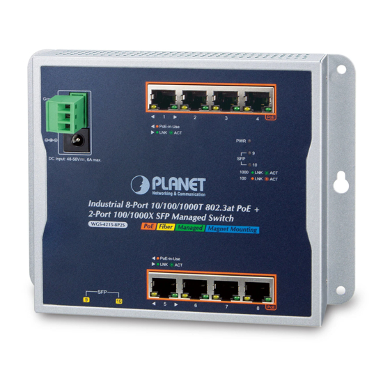
1. Package Contents Thank you for purchasing PLANET Industrial Wall-mount Managed Gigabit Switch, WGS-804HPT and WGS-4215 series. The table below shows the models with the number of ports: 10/100/1000T 802.3at PoE 100/1000 SFP Fiber Model Name Copper Ports Ports Optical Interface WGS-4215-8T –... -
Page 4: Requirements
2. Requirements z Workstations running Windows XP/2003/Vista/7/8/2008/10, MAC OS X or later, Linux, UNIX, or other platforms are compatible with TCP/IP protocols. z Workstations are installed with Ethernet NIC (Network Interface Card) z Ethernet Port Connection Network cables -- Use standard network (UTP) cables with RJ45 connectors. The above PC is installed with Web browser and JAVA runtime environment plug-in. -
Page 5: Wiring The Power Inputs
Model WGS-4215-8T 12~48V DC, 24V AC 12~48V DC, 24V AC WGS-4215-8T2S 12~48V DC, 24V AC 12~48V DC WGS-804HPT 48~56V DC 48~56V DC WGS-4215-8P2S 48~56V DC 48~56V DC WGS-4215-16P2S 48~56V DC 48~56V DC Max power requirement also rely on the real site application. Note 10/100/1000BASE-T RJ45 Port 3-pin Terminal Block... -
Page 6: Terminal Block Connector Pinout
Wall-mount Managed switch. 1. The wire gauge should be in the range from 12 to 24 AWG. 2. The device must be grounded. Note 3.2 DC Power Jack WGS-804HPT/WGS-4215-8P2S/WGS-4215-16P2S requires 48V~56V power input and WGS-4215-8T/WGS-4215-8T2S requires DC 12~48V power input. Should you have the issue of power connection, please contact your local sales representative. -
Page 7: Hardware Installation
Step 1: It is required 4 holes with 8mm diameter on the wall; the distance between the 2 holes is 133mm (WGS-804HPT/WGS-4215-8T), 163mm (WGS-4215-8T2S/WGS-4215-8P2S), 230 mm (WGS-4215-16P2S) and the line through them must be horizontal. Step 2: Install a conductor pipe inside the board hole and flush the edge of the conductor pipe with the wall surface. -
Page 8: Magnet Installation
4.2 Magnet Installation To install the Wall-mount Managed Switch on a magnetic surface, simply follow the following diagram: 4.2.1 Magnet Installation of WGS-4215-16P2S Step 1: There are six holes in front, using six sets of magnets to install. Please refer to the following. Step 2: Turn the switch to the back, then screw the magnet to the middle hole. -
Page 9: Din-Rail Mount Installation
As the magnetic mounting does not fix completely, when deploying the switch please be aware that the equipment will not fall or break due to vibration or dragging. Warnin g Please use the screw from the Magnet kit to avoid breaking the device. Note 4.3 DIN-rail Mount Installation The DIN-rail kit is included in the package. When the wall-mount application for the Wall-mount Managed Switch needs to be replaced with DIN-rail application, please refer to the following figures to screw the DIN-rail on the Wall-mount Managed Switch. To hang up the Wall-mount Managed Switch, follow the steps below:... - Page 10 Step 2: Lightly insert the DIN-rail into the track. Push Click Step 3: Check whether the DIN-rail is tightly on the track.
-
Page 11: Web Login
5. Web Login 5.1 Starting Web Management The following shows how to start up the Web Management of the Wall-mount Managed Switch. Note the Wall-mount Managed Switch is configured through an Ethernet connection. Please make sure the manager PC must be set to the same IP subnet address. - Page 12 2. When the following dialog box appears, please enter “admin” in both the default user name and password fields. The login screen in Figure 5-2 appears. Default IP Address: 192.168.0.100 Default Username: admin Default Password: admin Figure 5-2: Web Login Screen 3. After entering the password, the main screen appears as Figure 5-3 shows. The following web screen is based on the WGS-4215-8T2S. The display of the WGS-4215-8T2S is the same as those of the WGS- 804HPT and WGS-4215-8T/WGS-4215-8P2S/WGS-4215-16P2S. Note...
- Page 13 Figure 5-3: Web Main Screen of Wall-mount Managed Switch The Switch Menu on the left of the Web page lets you access all the commands and statistics the Wall-mount Managed Switch provides. Figure 5-4: Switch Menu Now, you can use the Web management interface to continue the Switch management.
-
Page 14: Saving Configuration Via The Web
5.2 Saving Configuration via the Web In the Wall-mount Managed Switch, the running configuration file stores in the RAM. In the current version, the running configuration sequence of running- config can be saved from the RAM to FLASH by “Save Configurations to FLASH” function, so that the running configuration sequence becomes the startup configuration file, which is called configuration save. -
Page 15: Telnet Login
6. Telnet Login The Wall-mount Managed Switch also supports Telnet for remote management. The switch asks for user name and password for remote login when using Telnet; please use “admin” for both username and password. Default IP address: 192.168.0.100 Username: admin Password: admin Figure 6-1: Wall-mount Managed Switch Telnet Login Screen The user can now enter commands to manage the Wall-mount Managed Switch. -
Page 16: Configuring Ip Address
2. The screen displays the current IP address shown in Figure 6-2. Figure 6-2: IP Information Screen Configuration of the IP Address 3. At the “#” prompt, enter the following command and press <Enter> as shown in Figure 6-3. WGS-4215-8P2S# configure terminal WGS-4215-8P2S (config)# ip address 192.168.1.100 mask 255.255.255.0 WGS-4215-8P2S (config)# ip default gateway 192.168.1.254... -
Page 17: Storing The Current Switch Configuration
The previous command would apply the following settings for the Wall-mount Managed Switch. IP Address: 192.168.1.100 Subnet Mask: 255.255.255.0 Gateway: 192.168.1.254 Figure 6-3: Configuring IP Address Screen 4. Repeat step 1 to check if the IP address has changed. 6.2 Storing the Current Switch Configuration At the “#” prompt, enter the following command and press <Enter>. # copy running-config startup-config Figure 6-4: Saving Current Configuration Command Screen If the IP is successfully configured, the Wall-mount Managed Switch will apply the... -
Page 18: Recovering Back To Default Configuration
5 seconds. After the device is rebooted, you can log in the Web interface management within the same subnet of 192.168.0.xx. Figure 7-1: WGS-804HPT/WGS-4215-8T Reset Button Figure 7-2: WGS-4215-8T2S/WGS-4215-8P2S Reset Button 100/1000X Reset Figure 7-3: WGS-4215-16P2S Reset Button... -
Page 19: Customer Support
Switch support team email address: support@planet.com.tw WGS-804HPT/WGS-4215-8T/WGS-4215-8T2S/WGS-4215-8P2S/WGS-4215-16P2S User’s Manual: https://www.planet.com.tw/en/support/downloads?&method=keyword&keyword=W GS&view=3#list Copyright © PLANET Technology Corp. 2018. Contents are subject to revision without prior notice. PLANET is a registered trademark of PLANET Technology Corp. All other trademarks belong to their respective owners.
Need help?
Do you have a question about the WGS-4215-8P2S and is the answer not in the manual?
Questions and answers