
Subscribe to Our Youtube Channel
Related Manuals for Planet Networking & Communication FGSD-1008HPS


Summary of Contents for Planet Networking & Communication FGSD-1008HPS
- Page 1 User’s Manual of FGSW-Series 8/16/24-Port 10/100Mbps 802.3at PoE + 2-Port Gigabit TP/SFP Combo Managed PoE+ Switch FGSD-1008HPS / FGSW-1816HPS FGSW-2624HPS / FGSW-2624HPS4...
- Page 2 Do not dispose of WEEE as unsorted municipal waste and have to collect such WEEE separately. Revision PLANET 8/16/24-Port 10/100Mbps 802.3at PoE + 2-Port Gigabit TP/SFP Combo Managed PoE+ Switch User's Manual FOR MODELS: FGSD-1008HPS/FGSW-1816HPS/FGSW-2624HPS/FGSW-2624HPS4 REVISION: 3.0 (October, 2020) Part No: EM-FGSW-Series_v3.0...
-
Page 3: Table Of Contents
User’s Manual of FGSW-Series TABLE OF CONETNTS 1. INTRODUCTION ........................8 1.1 Packet Contents ............................8 1.2 Product Description ............................. 9 1.3 How to Use This Manual ..........................13 1.4 Product Features ............................14 1.5 Product Specifications ..........................17 2. INSTALLATION ........................23 2.1 Hardware Description .......................... - Page 4 User’s Manual of FGSW-Series 4.2.3.1 IPv4 ................................51 4.2.3.2 IPv6 ................................51 4.2.4 SNMP Settings ..............................52 4.2.4.1 SNMP View Table ............................53 4.2.4.2 SNMP Group Table ............................ 54 4.2.4.3 SNMP User Table ............................55 4.2.4.4 SNMP Community Table..........................56 4.2.4.5 SNMP Host Table ............................
- Page 5 User’s Manual of FGSW-Series 4.6.2 QoS Group Member ............................100 4.6.3 QoS Mode Set ..............................101 4.6.4 QoS Out Queue Aging ............................102 4.6.5 QoS Remap ............................... 103 4.6.6 Class of Service ..............................104 4.6.7 802.1p-based QoS ............................105 4.6.8 DSCP-based Priority ............................106 4.6.9 TCP/UDP Port-based QoS ..........................
- Page 6 User’s Manual of FGSW-Series 4.9.3.2 IGMP Snooping Router Ports Settings ....................156 4.9.3.3 IGMP Snooping Groups .......................... 157 4.9.3.4 IGMP Snooping Ports ..........................158 4.9.4 MLD Snooping ..............................159 4.9.4.1 MLD Snooping Settings ........................... 159 4.9.4.2 MLD Snooping Router Ports Settings ...................... 160 4.9.4.3 MLD Snooping Groups ..........................
- Page 7 User’s Manual of FGSW-Series 6.5 Delete Command ............................191 6.6 Disable Command ............................ 191 6.7 Enable Command ............................. 192 6.8 Exit Command ............................192 6.9 Reboot Command ............................ 192 6.10 Restart Command ..........................193 6.11 Save Command ............................193 6.12 Show Command ............................. 193 7.
-
Page 8: Introduction
PLANET 8/16/24-port 10/100Mbps 802.3at PoE + 2-port Gigabit TP/SFP Combo Managed PoE+ Switch Series, FGSD-1008HPS, FGSW-1816HPS, FGSW-2624HPS and FGSW-2624HPS4, comes with the multi-port Fast Ethernet Switch and SFP fiber optic connectibility and robust Layer 2 features. The descriptions of this series are shown below: FGSD-1008HPS 8-Port 10/100TX 802.3at PoE + 2-Port Gigabit TP/SFP Combo Managed Ethernet Switch (120W) -
Page 9: Product Description
User’s Manual of FGSW-Series 1.2 Product Description PLANET’s newly-revised Layer 2 Managed PoE+ Switch series is designed for enterprises and industries where a network of PDs can be centrally managed. The Switch’s management functions have been enhanced to include intelligent PoE management, IPv6 management, ACL, GVRP, and more. - Page 10 User’s Manual of FGSW-Series Built-in Unique PoE Functions for Surveillance Management As the managed PoE+ Switch for surveillance network, it features the following intelligent PoE management functions: PD Alive Check PoE Port Sequence PoE Schedule Intelligent Powered Device Alive Check The Managed PoE+ Switch can be configured to monitor a connected PD status in real time via ping action.
- Page 11 User’s Manual of FGSW-Series PoE Port Sequence To prevent all the PoE ports of the Managed PoE+ Switch from being active at the same time when the Switch has booted up, the PoE ports of the Managed PoE+ Switch can be configured to allow each port to be activated at an interval time. In addition, the “Delay”...
- Page 12 User’s Manual of FGSW-Series Managed PoE+ Switch can be managed via any standard management software. For text-based management, the switch can be accessed via Telnet. Moreover, the Managed PoE+ Switch offers secure remote management by supporting SNMPv3 connections which encrypt the packet content at each session. Flexible and Extendable Uplink Solution The Managed PoE+ Switch provides 2 extra Gigabit TP/SFP combo interfaces supporting 10/100/1000BASE-T RJ45 copper to connect with surveillance network devices such as NVR, Video Streaming Server or NAS to facilitate surveillance...
-
Page 13: How To Use This Manual
User’s Manual of FGSW-Series 1.3 How to Use This Manual This User’s Manual is structured as follows: Section 2, INSTALLATION The section explains the functions of the Managed PoE+ Switch and how to physically install the Managed PoE+ Switch. Section 3, SWITCH MANAGEMENT The section contains the information about the software function of the Managed PoE+ Switch. -
Page 14: Product Features
User’s Manual of FGSW-Series 1.4 Product Features Physical Port ■ 8/16/24 10/100BASE-TX RJ45 copper ports with IEEE 802.3at/af PoE+ injector function ■ 2 10/100/1000BASE-T Gigabit RJ45 copper ports (Combo Interface) ■ 2 1000BASE-X mini-GBIC/SFP slots (Combo Interface) ■ RJ45 console interface for switch basic management and setup ■... - Page 15 User’s Manual of FGSW-Series Protocol VLAN Provider Bridging (VLAN Q-in-Q) support (IEEE 802.1ad) GVRP Voice VLAN ■ Supports Spanning Tree Protocol STP (IEEE 802.1D Spanning Tree Protocol) RSTP (IEEE 802.1w Rapid Spanning Tree Protocol) MSTP (IEEE 802.1s Multiple Spanning Tree Protocol) STP BPDU filtering, BPDU Guard ■...
- Page 16 User’s Manual of FGSW-Series Management ■ IPv4 and IPv6 dual stack management ■ Switch management interface RJ45 Console local management Web switch management Telnet command line interface SNMP v1, v2c and v3 ■ BOOTP and DHCP for IP address assignment ■...
-
Page 17: Product Specifications
User’s Manual of FGSW-Series 1.5 Product Specifications Product FGSD-1008HPS Hardware Specifications Copper Ports 8 10/100BASE-TX RJ45 Auto-MDI/MDI-X ports PoE Injector Port 8 802.3af/802.3at PoE+ injector ports Gigabit Copper Ports 2 10/100/1000BASE-T RJ45 auto-MDI/MDI-X ports SFP/mini-GBIC Slots 2 1000BASE-X SFP interfaces, shared with Port-9 to Port-10 <... - Page 18 User’s Manual of FGSW-Series Provider Bridging (VLAN Q-in-Q) support (IEEE 802.1ad) GVRP Voice VLAN IEEE 802.3ad LACP supports one 2-port trunk group; static trunk supports one 2-port Link Aggregation trunk group IEEE 802.1D Spanning Tree Protocol (STP) IEEE 802.1w Rapid Spanning Tree Protocol (RSTP) Spanning Tree Protocol IEEE 802.1s Multiple Spanning Tree Protocol (MSTP) STP BPDU filtering, BPDU Guard...
- Page 19 User’s Manual of FGSW-Series IEEE 802.1w Rapid Spanning Tree Protocol IEEE 802.1s Multiple Spanning Tree Protocol IEEE 802.1p Class of Service IEEE 802.1Q VLAN tagging IEEE 802.1ab LLDP IEEE 802.3af Power over Ethernet IEEE 802.3at Power over Ethernet Plus RFC 2068 HTTP RFC 1112 IGMP version 1 RFC 2236 IGMP version 2 RFC 3376 IGMP version 3...
- Page 20 User’s Manual of FGSW-Series Product FGSW-1816HPS FGSW-2624HPS FGSW-2624HPS4 Hardware Specifications 16 10/100BASE-TX RJ45 Copper Ports 24 10/100BASE-TX RJ45 Auto-MDI/MDI-X ports Auto-MDI/MDI-X ports 16 802.3af/802.3at PoE+ PoE Injector Port 24 802.3af/802.3at PoE+ injector ports injector ports Gigabit Copper Ports 2 10/100/1000BASE-T RJ45 auto-MDI/MDI-X ports SFP/mini-GBIC Slots 2 1000BASE-X SFP interfaces, shared with Gigabit copper ports Console...
- Page 21 User’s Manual of FGSW-Series Layer 2 Functions TX/RX/both Port Mirroring Many-to-1 monitor Port-based VLAN, up to 18 VLAN groups IEEE 802.1Q tagged VLAN Port-based VLAN, up to 26 VLAN groups - Up to 256 VLAN groups, IEEE 802.1Q tagged VLAN - Up to 256 VLAN groups, out of 4094 VLAN IDs out of 4094 VLAN IDs VLAN...
- Page 22 User’s Manual of FGSW-Series PLANET smart discovery utility Secure Management Interfaces SNMP v3, SSHv2, TLS v1.2 Standards Conformance Regulatory Compliance FCC Part 15 Class A, CE IEEE 802.3 10BASE-T IEEE 802.3u 100BASE-TX IEEE 802.3z Gigabit SX/LX IEEE 802.3ab Gigabit 1000T IEEE 802.3x flow control and back pressure IEEE 802.3ad port trunk with LACP IEEE 802.1D Spanning Tree Protocol...
-
Page 23: Installation
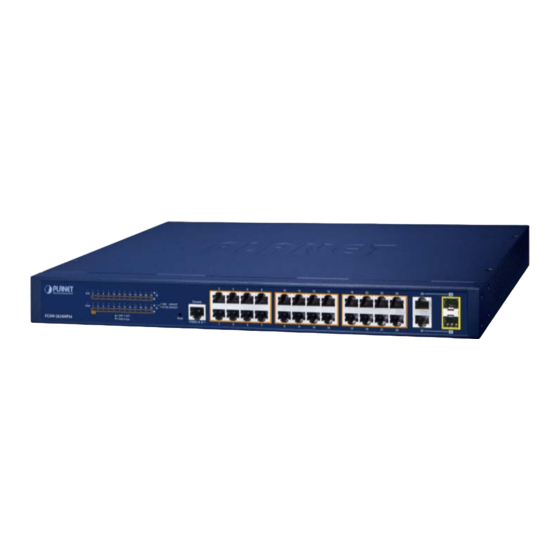
The front panel provides a simple interface monitoring the Managed PoE+ Switch. Figure 2-1 shows the front panels of the Managed PoE+ Switches. FGSD-1008HPS Front Panel FGSW-1816HPS Front Panel FGSW-2624HPS Front Panel FGSW-2624HPS4 Front Panel Figure 2-1: Front Panels of Managed PoE+ Switch Series Model ■... - Page 24 User’s Manual of FGSW-Series Reset Button Pressed and Released Function < 5 sec: System Reboot Reboot the Managed PoE+ Switch. Reset the Managed PoE+ Switch to Factory Default configuration. The Managed PoE+ Switch will then reboot and load the default settings as below: 。...
-
Page 25: Led Indications
The front panel LEDs indicates instant status of power and system status, fan status, port links / PoE in-use and data activity; helps monitor and troubleshoot when needed. Figure 2-2 shows the LED indications of the Managed PoE+ Switches. FGSD-1008HPS LED Indication System Color... - Page 26 User’s Manual of FGSW-Series FGSW-1816HPS LED Indication System Color Function Green Lights to indicate the Switch has power. Lights to indicate the system is working. Green Off to indicate the system is booting. Per 10/100Mbps Port with PoE Interfaces (Port1 to Port16) Color Function Lights...
- Page 27 User’s Manual of FGSW-Series FGSW-2624HPS and FGSW-2624HPS4 LED Indication Figure 2-2: Managed PoE+ Switch Series LEDs on Front Panel System Color Function Green Lights to indicate the Switch has power. Lights to indicate the system is working. Green Off to indicate the system is booting. ...
-
Page 28: Switch Rear Panel
The rear panel of the Managed PoE+ Switch indicates an AC inlet power socket, which accepts input power from 100 to 240V AC, 50-60Hz. Figure 2-3 shows the rear panel of the Managed PoE+ Switch. FGSD-1008HPS Rear Panel FGSW-1816HPS Rear Panel FGSW-2624HPS Rear Panel FGSW-2624HPS 4 Rear Panel Figure 2-3: Rear Panels of Managed PoE+ Switch Series ■... -
Page 29: Install The Switch
User’s Manual of FGSW-Series 2.2 Install the Switch This section describes how to install your Managed PoE+ Switch and make connections to the Managed PoE+ Switch. Please read the following topics and perform the procedures in the order being presented. To install your Managed PoE+ Switch on a desktop or shelf, simply complete the following steps. -
Page 30: Rack Mounting
User’s Manual of FGSW-Series Step5: Supply power to the Managed PoE+ Switch. Connect one end of the power cable to the Managed PoE+ Switch. Connect the power plug of the power cable to a standard wall outlet. When the Managed PoE+ Switch receives power, the Power LED should remain solid Green. 2.2.2 Rack Mounting To install the Managed PoE+ Switch in a 19-inch standard rack, please follow the instructions described below. -
Page 31: Installing The Sfp Transceiver
User’s Manual of FGSW-Series Step6: Proceeds with the steps 4 and 5 of session 2.2.1 Desktop Installation to connect the network cabling and supply power to the Managed PoE+ Switch. 2.2.3 Installing the SFP Transceiver The sections describe how to insert an SFP transceiver into an SFP slot. The SFP transceivers are hot-pluggable and hot-swappable. - Page 32 User’s Manual of FGSW-Series Approved PLANET SFP Transceivers PLANET Managed PoE+ Switch supports both Single mode and Multi-mode SFP transceiver. The following list of approved PLANET SFP transceivers is correct at the time of publication: Gigabit SFP Transceiver Modules MGB-GT SFP-Port 1000BASE-T Module MGB-SX...
- Page 33 User’s Manual of FGSW-Series Connect the Fiber Cable Insert the duplex LC connector into the SFP transceiver. Connect the other end of the cable to a device with SFP transceiver installed. Check the LNK/ACT LED of the SFP slot on the front of the Managed PoE+ Switch. Ensure that the SFP transceiver is operating correctly.
-
Page 34: Switch Management
User’s Manual of FGSW-Series 3. SWITCH MANAGEMENT This chapter explains the methods that you can use to configure management access to the Managed PoE+ Switch. It describes the types of management applications and the communication and management protocols that deliver data between your management device (workstation or personal computer) and the system. -
Page 35: Management Access Overview
User’s Manual of FGSW-Series 3.2 Management Access Overview The Managed PoE+ Switch gives you the flexibility to access and manage it using any or all of the following methods: An administration console Web browser interface An external SNMP-based network management application The administration console and Web browser interface support are embedded in the Managed PoE+ Switch software and are available for immediate use. -
Page 36: Administration Console
User’s Manual of FGSW-Series 3.3 Administration Console The administration console is an internal, character-oriented, and command line user interface for performing system administration such as displaying statistics or changing option settings. Using this method, you can view the administration console from a terminal, personal computer, Apple Macintosh, or workstation connected to the Managed PoE+ Switch 's RJ45 console (serial) port. - Page 37 User’s Manual of FGSW-Series ♦ Baud: 115200 ♦ Data bits: 8 ♦ Parity: None ♦ Stop bits: 1 ♦ Flow control: None Figure 3-2: COM Port Configuration This management method is often preferred because you can remain connected and monitor the system during system reboots. Also, certain error messages are sent to the serial port, regardless of the interface through which the associated action was initiated.
-
Page 38: Web Management
Microsoft Internet Explorer 8.0 or later. The following web screen is based on the FGSW-2624HPS4; the display of the FGSW-2624HPS4 is the same as that of the FGSD-1008HPS, FGSW- 1816HPS and FGSW-2624HPS. Figure 3-4: Web Main Screen of Managed PoE+ Switch... -
Page 39: Snmp-Based Network Management
User’s Manual of FGSW-Series 3.5 SNMP-Based Network Management You can use an external SNMP-based application to configure and manage the Managed PoE+ Switch, such as SNMP Network Manager, HP Openview Network Node Management (NNM) or What’s Up Gold. This management method requires the SNMP agent on the Managed PoE+ Switch and the SNMP Network Management Station to use the same community string. -
Page 40: Planet Smart Discovery Utility
User’s Manual of FGSW-Series 3.6 PLANET Smart Discovery Utility For easily listing the Managed PoE+ Switch in your Ethernet environment, the PLANET Smart Discovery Utility is an ideal solution. The following installation instructions are to guide you to running the PLANET Smart Discovery Utility. Deposit the PLANET Smart Discovery Utility in administrator PC. - Page 41 User’s Manual of FGSW-Series This utility shows all necessary information from the devices, such as MAC Address, Device Name, firmware version, and Device IP Subnet address. It can also assign new password, IP Subnet address and description for the devices. After setup is completed, press “Update Device”, “Update Multi”...
-
Page 42: Web Configuration
User’s Manual of FGSW-Series 4. WEB CONFIGURATION This section introduces the configuration and functions of the Web-based management from Managed PoE+ Switch. About Web-based Management The Managed PoE+ Switch offers management features that allow users to manage the Managed PoE+ Switch from anywhere on the network through a standard browser such as Microsoft Internet Explorer or Google Chrome. - Page 43 User’s Manual of FGSW-Series Logging on the Managed PoE+ Switch Use Internet Explorer 8.0 or above Web browser. Enter the factory-default IP address to access the Web interface. The factory-default IP Address is shown as follows: http://192.168.0.100 When the following login screen appears, please enter the default username "admin" with password “admin” (or the username/password you have changed via console) to login the main screen of Managed PoE+ Switch.
- Page 44 User’s Manual of FGSW-Series Figure 4-1-3: Web Main Page Now, you can use the Web management interface to continue the switch management or manage the Managed PoE+ Switch by Web interface. The Switch Menu on the left of the web Page let you access all the commands and statistics the Managed PoE+ Switch provides.
-
Page 45: Main Web Page
User’s Manual of FGSW-Series 4.1 Main Web Page The Managed PoE+ Switch provides a Web-based browser interface for configuring and managing it. This interface allows you to access the Managed PoE+ Switch using the Web browser of your choice. This chapter describes how to use the Managed PoE+ Switch’s Web browser interface to configure and manage it. - Page 46 User’s Manual of FGSW-Series System Hot Key Icons The system hot keys icons are in the right side of the Managed PoE+ Switch’s web page, from left to right side is System Up Time, refresh button, save config button, reboot button and logout button. Main Menu Using the onboard web agent, you can define system parameters, manage and control the Managed PoE+ Switch, and all its ports, or monitor network conditions.
- Page 47 User’s Manual of FGSW-Series Device Information Item Description Device Type Display the device type information. Device Name Display the device name information. Location Display the device location information. Contact Display the device contact information. MAC Address Display the device MAC address information. IP Address Display the device IP address information.
-
Page 48: System
User’s Manual of FGSW-Series 4.2 System Use the system menu items to display and configure basic administrative details of the Managed PoE+ Switch. Under the system the following topics are provided to configure and view the system information. This section has the following items: Access system web page, you can view system functions of the Managed PoE+ Switch, the screen in Figure 4-2-1 appears and... -
Page 49: System Information
User’s Manual of FGSW-Series 4.2.1 System Information The System Infomation Page provides information for the current device information. System Information Page helps a switch administrator to identify the hardware MAC address, firmware version and system uptime and also config the device name, comment, location and contact information. -
Page 50: User Configuration
User’s Manual of FGSW-Series 4.2.2 User Configuration The User configuration includes the User Name,Password and Confirm Password. The configured column is used to view or change the User Name and Password. The screen in Figure 4-2-3 appears. Figure 4-2-3: User Configuration Page Screenshot The Current column is used to show the user configuration. -
Page 51: Ip Configuration
User’s Manual of FGSW-Series 4.2.3 IP Configuration The IP configuration includes the IPv4 subnet address setting and IPv6 subnet address setting, the configured column is used to view or change the IP configuration. 4.2.3.1 IPv4 The IPv4 configuration includes the IPv4 Address, Subnet Mask, Default Gateway and DNS Server, also the DHCPv4 Client Enable function. -
Page 52: Snmp Settings
User’s Manual of FGSW-Series 4.2.4 SNMP Settings The Simple Network Management Protocol (SNMP) is an application layer protocol that facilitates the exchange of management information between network devices. It is part of the Transmission Control Protocol/Internet Protocol (TCP/IP) protocol suite. SNMP enables network administrators to manage network performance, find and solve network problems, and plan for network growth. -
Page 53: Snmp View Table
User’s Manual of FGSW-Series 4.2.4.1 SNMP View Table The SNMP View Table provide to set view rules for allow or deny access to certain MIB objects, the configured column is used to input the view name, subtree OID and change the view type. The screen in Figure 4-2-6 appears. -
Page 54: Snmp Group Table
User’s Manual of FGSW-Series 4.2.4.2 SNMP Group Table The SNMP View Table provide to set SNMP Group settings, the configured column is used to input the group name, change the Read, Write, Notify view type and Security Model /Level. The screen in Figure 4-2-7 appears. -
Page 55: Snmp User Table
User’s Manual of FGSW-Series Buttons : press this button to take affect. : press this button to delete. The SNMP group needs to create the view before group create. 4.2.4.3 SNMP User Table The SNMP User Table provide to set SNMP user settings, the configured column is used to input the user name, select the group name and input the password for Auth-Protocol MD5 /Priv-Protocol DES. -
Page 56: Snmp Community Table
User’s Manual of FGSW-Series 4.2.4.4 SNMP Community Table The SNMP User Table provides to set SNMP community settings; the configured column is used to input the community name, and select the group name for access group as the screen in Figure 4-2-9 appears. -
Page 57: Snmp Host Table
User’s Manual of FGSW-Series 4.2.4.5 SNMP Host Table The SNMP Host Table provides to set SNMP host settings. The configured column is used to input the host IP address, and select the security model, security level and community string for SNMPv3 user as the screen in Figure 4-2-10 appears. -
Page 58: Snmp Configuration
User’s Manual of FGSW-Series 4.2.4.6 SNMP Configuration The SNMP Host Table provides to set SNMP settings; the configured column is used to input the selected operation modes of SNMP State, SNMP Trap and SNMP Link Change Traps as the screen in Figure 4-2-11 appears. -
Page 59: Ntp Settings
User’s Manual of FGSW-Series 4.2.5 NTP Settings On this page. NTP, an acronym for Network Time Protocol, is for synchronizing the clocks of computer systems. NTP uses UDP (data grams) as transport layer. You can specify NTP Servers and set GMT time zone. The NTP configuration screen in Figure 4-2-12 appears. -
Page 60: Syslog Settings
User’s Manual of FGSW-Series 4.2.6 Syslog Settings The Syslog settings provide to set system log settings, the configured column is used to select the related settings of Syslog settings as the screen in Figure 4-2-13 appears. Figure 4-2-13: Syslog Settings Configuration Page Screenshot The page includes the following fields: Object Description... -
Page 61: Factory Default
User’s Manual of FGSW-Series 4.2.7 Factory Default You can reset the configuration of the Managed PoE+ Switch on this page. Only the IP configuration is retained. The new configuration is available immediately, which means that no restart is necessary. The Factory Default screen in Figure 4-2-14 appears. -
Page 62: Configuration
User’s Manual of FGSW-Series 4.2.8 Configuration The configuration includes backup and reload the current configuration of the Managed PoE+ Switch to/from the local management station. 4.2.8.1 Backup The backup configuration provides downloading the Managed PoE+ Switch configuration file (Current.tar.gz) to local management station as the screen in Figure 4-2-15 appears. -
Page 63: Firmware Update
User’s Manual of FGSW-Series 4.2.9 Firmware Update This page facilitates an update on the firmware controlling the switch as the Web Firmware Upgrade screen in Figure 4-2-17 appears. Figure 4-2-17: Web Firmware Update Page Screenshot To open Firmware Upgrade screen, perform the following: Click System ->... -
Page 64: Poe Configuration
User’s Manual of FGSW-Series 4.3 PoE Configuration On the Access PoE configuration web page, you can view PoE function information of the Managed PoE+ Switch as the screen Figure 4-3-1 appears. Figure 4-3-1: Managed PoE+ Switch PoE Configuration Web Page PoE Configuration Item Description... -
Page 65: Poe Port Settings
User’s Manual of FGSW-Series 4.3.1 PoE Port Settings This page provides configuration for all PoE ports as the PoE Port settings screen in Figure 4-3-3 appears. Figure 4-3-3: PoE Port Settings Configuration Page Screenshot The page includes the following fields: Object Description •... -
Page 66: Poe Alive Check
User’s Manual of FGSW-Series Buttons : press this button to take effect. : press this button to refresh information. 4.3.2 PoE Alive Check The Managed PoE+ Switch can be configured to monitor connected PD’s status in real-time via ping action. Once the PD stops working and without response, Managed PoE+ Switch is going to restart PoE port port power, and bring the PD back to work. - Page 67 User’s Manual of FGSW-Series System is going to check the PD again according to the reboot time. If ou can not make sure precisely booting time, we suggest you to set it longer. Port Settings • Port Select specific PoE port for further configuration and list all ports on this page. •...
-
Page 68: Poe Port Sequential
User’s Manual of FGSW-Series 4.3.3 PoE Port Sequential This page allows the user to configure the PoE Ports started up interval time as the PoE Port Sequential configuration screen in Figure 4-3-5 appears. Figure 4-3-5: PoE Port Sequential Configuration Page Screenshot The page includes the following fields: Object Description... -
Page 69: Poe Schedule
User’s Manual of FGSW-Series 4.3.4 PoE Schedule This page allows the user to define PoE schedule and schedule power recycle. PoE Schedule Besides being used as an IP Surveillance, the Managed PoE+ Switch is certainly applicable to constructing any PoE network including VoIP and Wireless LAN. - Page 70 User’s Manual of FGSW-Series Object Description • Port Selection Select specific PoE port for further configuration. • Port List all PoE Port for configure PoE schedule function. • State: xxxxx change to This column allows user to configure the PoE Port Start Up interval time. Delay time range is from 1 seconds to 300 seconds.
-
Page 71: Basic Configuration
User’s Manual of FGSW-Series 4.4 Basic Configuration On the Access Basic configuration web page, you can view Port management function informations of the Managed PoE+ Switch as the screen in Figure 4-4-1 appears. Figure 4-4-1: Managed PoE+ Switch Basic Configuration Web Page Basic Configuration Item Description... -
Page 72: Port Configuration
User’s Manual of FGSW-Series 4.4.1 Port Configuration This page displays current port configurations and each port can also be configured here as the Port configuration screen in Figure 4-4-2 appears. Figure 4-4-2 : Port Configuration Page Screenshot The page includes the following fields: Object Description •... - Page 73 User’s Manual of FGSW-Series • Auto Nego. Display per port current auto negotiation setting mode. • Flow Control Display per port current flow control setting mode. Status • Learning Display per port current learning setting mode. • Speed/Duplex Display per port current speed/duplex mode. •...
-
Page 74: Port Mirroring
User’s Manual of FGSW-Series 4.4.2 Port Mirroring On this page, port mirroring provides monitoring network traffic that forwards a copy of each incoming or outgoing packet from one port of a Managed PoE+ Switch to another port where the packet can be studied. It enables the manager to keep close track of switch performance and alter it if necessary. - Page 75 User’s Manual of FGSW-Series The page includes the following fields: Object Description • Source Port Selection Select specific port for monitoring incoming and outgoing flow from the port. • Destination Port Selection Select the specific port for copy flow data from source ports and then forward to message analyzer to analyze message, and finally analysis of message forward to destination port.
-
Page 76: Broadcast Storm Control
User’s Manual of FGSW-Series 4.4.3 Broadcast Storm Control Storm control for the switch is configured on this page. There are a broadcast storm rate control, multicast storm rate control, and unicast storm rate control. These only affect flooded frames, i.e. frames with a (VLAN ID, DMAC) pair not present on the MAC Address table. - Page 77 User’s Manual of FGSW-Series Set reception period and the available options are shown below: • Period for (Giga/100/10) 200us/2ms/20ms 1ms/10ms/100ms 10ms/10ms/10ms 100ms/100ms/100ms Storm Control State Select specific port for further configuration. • Port Selection • Enable or disable the broadcast storm control function. Broadcast •...
-
Page 78: Bandwidth Control
User’s Manual of FGSW-Series 4.4.4 Bandwidth Control This page allows you to configure the incoming and outgoing bandwidth control settings for all switch ports as the bandwidth control screen in Figure 4-4-6 appears. Figure 4-4-6: Bandwidth Control Configuration Page Screenshot The page includes the following fields: Object Description... -
Page 79: Vlan Configuration
User’s Manual of FGSW-Series 4.5 VLAN Configuration 4.5.1 VLAN Overview A Virtual Local Area Network (VLAN) is a network topology configured according to a logical scheme rather than the physical layout. VLAN can be used to combine any collection of LAN segments into an autonomous user group that appears as a single LAN. - Page 80 User’s Manual of FGSW-Series VLAN Configuration Item Description VLAN Mode Configure VLAN Mode configuration settings on this web page. VLAN Group-based Entry Config Display and configure VLAN Group-based Entry Config function on this web page. VLAN Tag-based Entry Config Display and configure VLAN Tag-based Entry Config function on this web page. VLAN Port Config Display and configure VLAN Port Config function on this web page.
-
Page 81: Ieee 802.1Q Vlan
User’s Manual of FGSW-Series 4.5.2 IEEE 802.1Q VLAN In large networks, routers are used to isolate broadcast traffic for each subnet into separate domains. This Managed PoE+ Switch provides a similar service at Layer 2 by using VLANs to organize any group of network nodes into separate broadcast domains. - Page 82 User’s Manual of FGSW-Series ■ 802.1Q VLAN Tags The figure below shows the 802.1Q VLAN tag. There are four additional octets inserted after the source MAC address. Their presence is indicated by a value of 0x8100 in the Ether Type field. When a packet's Ether Type field is equal to 0x8100, the packet carries the IEEE 802.1Q/802.1p tag.
- Page 83 User’s Manual of FGSW-Series ■ Port VLAN ID Packets that are tagged (are carrying the 802.1Q VID information) can be transmitted from one 802.1Q compliant network device to another with the VLAN information intact. This allows 802.1Q VLAN to span network devices (and indeed, the entire network –...
- Page 84 User’s Manual of FGSW-Series ■ VLAN Classification When the switch receives a frame, it classifies the frame in one of two ways. If the frame is untagged, the switch assigns the frame to an associated VLAN (based on the default VLAN ID of the receiving port). But if the frame is tagged, the switch uses the tagged VLAN ID to identify the port broadcast domain of the frame.
-
Page 85: Vlan Mode
User’s Manual of FGSW-Series 4.5.3 VLAN Mode The VLAN Mode Page provide VLAN Mode configuration supported by the Managed PoE+ Switch as the VLAN Mode screen in Figure 4-5-2 appears. Figure 4-5-2: VLAN Mode Configuration Page Screenshot The Page includes the following fields: Object Description •... -
Page 86: Vlan Group-Based Entry Config
User’s Manual of FGSW-Series 4.5.4 VLAN Group-based Entry Config Adding Static Members to VLANs (VLAN Index) Use the VLAN Group Member Port to configure port members for the selected VLAN index. The VLAN Group-based Entry Config configuration can be monitored and modified here. Up to 26 VLANs are supported. This page allows for adding and deleting VLANs as well as adding and deleting port members of each VLAN as the VLAN Group-based Entry Config screen in Figure 4-5-3 appears. -
Page 87: Vlan Tag-Based Entry Config
User’s Manual of FGSW-Series Buttons : press this button to create a new specific VLAN group. : press this button to modify a specific VLAN group. : press this button to edit specific VLAN group. : press this button to delete specific VLAN group. 4.5.5 VLAN Tag-based Entry Config Use the VLAN Tag-based entry config to configure port members function for the selected VLAN index. - Page 88 User’s Manual of FGSW-Series • Priority Display the Priority state of specific VLAN group. • GVRP Forward Display the GVRP Forward state of specific VLAN group. • Action : press this button to edit specific VLAN group. : press this button to delete specific VLAN group. Buttons : press this button to create a new specific VLAN group.
- Page 89 User’s Manual of FGSW-Series • Port Display per port list of Managed PoE+ Switch. • Don’t care As a VLAN member of specific VLAN group without any action. • Add As a VLAN member, add the Tag action to the packet sent out by this port. •...
-
Page 90: Vlan Port Config
User’s Manual of FGSW-Series 4.5.6 VLAN Port Config This page is used for configuring the Managed PoE+ Switch port VLAN. The VLAN per port configuration page contains fields for managing ports that are part of a VLAN. The port default VLAN ID (PVID) is configured on the VLAN port configuration page. All untagged packets arriving to the device are tagged by the ports PVID. - Page 91 User’s Manual of FGSW-Series The VLAN Port configuration screen in Figure 4-5-6 is shown below. Figure 4-5-6 : VLAN Port Config Configuration Page Screenshot The page includes the following fields: Object Description • Port Selection Select specific port for VLAN settings. •...
- Page 92 User’s Manual of FGSW-Series • Port Display per port list. • PVID Display per port PVID information. • Tagging Display per port Tagging information. • Force VLAN Display per port Force VLAN Group information. Group • Uplink Display per port Uplink information. •...
-
Page 93: Protocol Vlan Config
User’s Manual of FGSW-Series 4.5.7 Protocol VLAN Config This page is used for configuring the Managed PoE+ Switch Protocol VLAN Config as the Protocol VLAN Config screen in Figure 4-5-7 appears. Figure 4-5-7 : Protocol VLAN Config Configuration Page Screenshot The page includes the following fields: Object Description... -
Page 94: Q-In-Q Port Config
User’s Manual of FGSW-Series 4.5.8 Q-in-Q Port Config This page is used for configuring the Managed PoE+ Switch Q-in-Q port VLAN function; the Q-in-Q port VLAN function configuration page contains fields for managing ports that are part of Q-in-Q VLAN. Understanding Nomenclature of the Switch ■... - Page 95 User’s Manual of FGSW-Series Q-in-Q Port Configuration The Q-in-Q Port configuration screen in Figure 4-5-8 is shown below. Figure 4-5-8 : Q-in-Q Port Configuration Page Screenshot The page includes the following fields: Object Description • Port Selection/Port Select specific port for Q-in-Q Port configuration./ List per port numbers. •...
-
Page 96: Q-In-Q Index Config
User’s Manual of FGSW-Series 4.5.9 Q-in-Q Index Config This page is used for configuring the Managed PoE+ Switch Q-in-Q port VLAN function; the Q-in-Q port VLAN function configuration page contains fields for managing ports that are part of Q-in-Q VLAN. Understanding Nomenclature of the Switch ■... - Page 97 User’s Manual of FGSW-Series Q-in-Q Index Configuration The Q-in-Q Index configuration screen in Figure 4-5-9 appears. Figure 4-5-9 : Q-in-Q Index Configuration Page Screenshot The page includes the following fields: Object Description • Type Set the type value of service Tag. •...
-
Page 98: Qos Configuration
User’s Manual of FGSW-Series 4.6 QoS Configuration 4.6.1 Understanding QoS Quality of Service (QoS) is an advanced traffic prioritization feature that allows you to establish control over network traffic. QoS enables you to assign various grades of network service to different types of traffic, such as multi-media, video, protocol-specific, time critical, and file-backup traffic. - Page 99 User’s Manual of FGSW-Series On the Access QoS configuration web page, you can view QoS management function informations of the Managed PoE+ Switch as the screen in Figure 4-6-1 appears. Figure 4-6-1: Managed PoE+ Switch QoS Configuration Web Page QoS Configuration Item Description QoS Group Member...
-
Page 100: Qos Group Member
User’s Manual of FGSW-Series 4.6.2 QoS Group Member This page allows you to configure the QoS group member for all switch ports as the QoS group member screen in Figure 4-6-2 appears. Figure 4-6-2: QoS Group Member Configuration Page Screenshot The page includes the following fields: Object Description... -
Page 101: Qos Mode Set
User’s Manual of FGSW-Series 4.6.3 QoS Mode Set This page allows you to configure the QoS mode settings for Managed PoE+ Switch as the QoS mode settings screen in Figure 4-6-3 appears. Figure 4-6-3 : QoS Mode Set Configuration Page Screenshot The page includes the following fields: Object Description... -
Page 102: Qos Out Queue Aging
User’s Manual of FGSW-Series 4.6.4 QoS Out Queue Aging This page allows you to configure the QoS Out Queue Aging settings for all switch ports as the QoS Out Queue Aging screen in Figure 4-6-4 appears. Figure 4-6-4: QoS Out Queue Aging Configuration Page Screenshot The page includes the following fields: Object Description... -
Page 103: Qos Remap
User’s Manual of FGSW-Series 4.6.5 QoS Remap This page allows you to configure the QoS Remap settings for all switch ports as the QoS Remap screen in Figure 4-6-5 appears. Figure 4-6-5: QoS Remap Configuration Page Screenshot The page includes the following fields: Object Description •... -
Page 104: Class Of Service
User’s Manual of FGSW-Series 4.6.6 Class of Service This page allows you to configure the QoS Class of Service settings for all switch ports as the QoS Class of Servic screen in Figure 4-6-6 appears. Figure 4-6-6: QoS Class of Service Configuration Page Screenshot The page includes the following fields: Object Description... -
Page 105: P-Based Qos
User’s Manual of FGSW-Series Button : press this button to take effect. 4.6.7 802.1p-based QoS This page allows you to configure the 802.1p-based QoS settings for Managed PoE+ Switch as the 802.1p-based QoS screen Figure 4-6-7 appears. Figure 4-6-7: 802.1p-based QoS Configuration Page Screenshot The page includes the following fields: Object Description... -
Page 106: Dscp-Based Priority
User’s Manual of FGSW-Series 4.6.8 DSCP-based Priority This page allows you to configure the DSCP-based Priority settings for Managed PoE+ Switch as the DSCP-based Priority screen in Figure 4-6-8 appears. Figure 4-6-8: DSCP-based Priority Configuration Page Screenshot The page includes the following fields: Object Description •... -
Page 107: Tcp/Udp Port-Based Qos
User’s Manual of FGSW-Series 4.6.9 TCP/UDP Port-based QoS This page allows you to configure the TCP/UDP Port-based QoS settings for Managed PoE+ Switch as the TCP/UDP Port-based QoS screen in Figure 4-6-9 appears. Figure 4-6-9: TCP/UDP Port-based QoS Configuration Page Screenshot The page includes the following fields: Object Description... -
Page 108: Acl Configuration
User’s Manual of FGSW-Series 4.7 ACL Configuration 4.7.1 Understanding ACL ACL is an acronym for Access Control List. It is the list table of ACEs, containing access control entries that specify individual users or groups permitted or denied to specific traffic objects, such as a process or a program. Each accessible traffic object contains an identifier to its ACL. -
Page 109: Acl Profile List
User’s Manual of FGSW-Series 4.7.2 ACL Profile List This page allows you to configure the ACL Profile List settings for Managed PoE+ Switch as the ACL Profile List screen in Figure 4-7-2 appears. Figure 4-7-2: ACL Profile List Configuration Page Screenshot The page includes the following fields: Object Description... - Page 110 User’s Manual of FGSW-Series : press this button to delete the specific ACL Profile. Buttons : press this button to complete the add ACL Profile procedure. : press this button to edit the specific ACL Profile. : press this button to delete the specific ACL Profile.
-
Page 111: Mac
User’s Manual of FGSW-Series 4.7.2.1 MAC The Access Control List configuration includes the function that is based on MAC address as the screen in Figure 4-7-3 appears. Figure 4-7-3: ACL Profile List-MAC Configuration Page Screenshot The page includes the following fields: Object Description •... - Page 112 User’s Manual of FGSW-Series 4.7.2.2 IP The Access Control List configuration includes the function that is based on IP address as the screen in Figure 4-7-4 appears. Figure 4-7-4: ACL Profile List-IP Configuration Page Screenshot The page includes the following fields: Object Description •...
-
Page 113: Ip_Ext
User’s Manual of FGSW-Series 4.7.2.3 IP_EXT The Access Control List configuration includes the function that is based on IP address extension as the screen in Figure 4-7-5 appears. Figure 4-7-5: ACL Profile List-IP Address Extension Configuration Page Screenshot The page includes the following fields: Object Description •... - Page 114 User’s Manual of FGSW-Series 255:255:255:0 255:255:240:0 255.255:0:0 255.0.0.0 240.0.0.0 • Source Port Configure the Source Port of Low and High. • Destination Port Configure the Destination Port of Low and High. • VID Configure the VID and the available range is 1-4094. •...
-
Page 115: Ipv6
User’s Manual of FGSW-Series 4.7.2.4 IPv6 The Access Control List configuration includes the function that is based on IPv6 address as the screen in Figure 4-7-6 appears. Figure 4-7-6: ACL Profile List-IPv6 Configuration Page Screenshot The page includes the following fields: Object Description •... -
Page 116: Advanced
User’s Manual of FGSW-Series 4.7.2.5 Advanced The Access Control List configuration includes the function that is based on IPv6 address as the screen in Figure 4-7-7appears. Figure 4-7-7: ACL Profile List-IPv6 Configuration Page Screenshot The page includes the following fields: Object Description •... - Page 117 User’s Manual of FGSW-Series • Source IP Address Configure the Source IP Address. • Source IP Mask Configure the Source IP Mask and the available options are shown below: 255:255:255:255 255:255:255:240 255:255:255:0 255:255:240:0 255.255:0:0 255.0.0.0 240.0.0.0 • Destination IP Address Configure the Destination IP Address.
-
Page 118: Acl Ctag Settings
User’s Manual of FGSW-Series 4.7.3 ACL Ctag Settings This page allows you to configure the ACL Ctag settings for Managed PoE+ Switch as the ACL Ctag settings configuration screen in Figure 4-7-8 appears. Figure 4-7-8: ACL Ctag Settings Configuration Page Screenshot The page includes the following fields: Object Description... -
Page 119: Acl Stag Settings
User’s Manual of FGSW-Series 4.7.4 ACL Stag Settings This page allows you to configure the ACL Stag settings for Managed PoE+ Switch as the ACL Stag settings configuration screen in Figure 4-7-9 appears. Figure 4-7-9: ACL Stag Settings Configuration Page Screenshot The page includes the following fields: Object Description... -
Page 120: Acl Vlan Settings
User’s Manual of FGSW-Series 4.7.5 ACL VLAN Settings This page allows you to configure the ACL VLAN settings for Managed PoE+ Switch as the ACL VLAN settings configuration screen in Figure 4-7-10 appears. Figure 4-7-10: ACL VLAN Settings Configuration Page Screenshot The page includes the following fields: Object Description... -
Page 121: Acl Bandwidth Settings
User’s Manual of FGSW-Series 4.7.6 ACL Bandwidth Settings This page allows you to configure the ACL bandiwdth settings for Managed PoE+ Switch as the ACL bandiwdth settings configuration screen in Figure 4-7-11 appears. Figure 4-7-11: ACL Bandwidth Settings Configuration Page Screenshot The page includes the following fields: Object Description... -
Page 122: Acl Dscp Settings
User’s Manual of FGSW-Series 4.7.7 ACL DSCP Settings This page allows you to configure the ACL DSCP settings for Managed PoE+ Switch as the ACL DSCP settings configuration screen in Figure 4-7-12 appears. Figure 4-7-12: ACL DSCP Settings Configuration Page Screenshot The page includes the following fields: Object Description... -
Page 123: Security
User’s Manual of FGSW-Series 4.8 Security On the Access Security configuration web page, you can view and configure Security functions of the Managed PoE+ Switch as the screen in Figure 4-8-1 appears: Figure 4-8-1: Managed PoE+ Switch Security Configuration Web Page Security Configuration Item Description... -
Page 124: Access Security
User’s Manual of FGSW-Series 4.8.1 Access Security This page allows you to configure the Access Security settings for Managed PoE+ Switch as the Access Security configuration screen in Figure 4-8-2 appears. Figure 4-8-2: Access Security Configuration Page Screenshot The page includes the following fields: Object Description •... -
Page 125: Port-Mac-Ip Binding
User’s Manual of FGSW-Series 4.8.2 Port-MAC-IP Binding The Port-MAC-IP Binding configuration provides the IPv4/IPv6 for basic security protection and filtering by checking the source IP address of the packet. Each port can be configured on the page to check whether the source IP address and the source port match. - Page 126 User’s Manual of FGSW-Series The page includes the following fields: Object Description • Port Selection Select specific port for Port-MAC-IP Port settings. • Status Configure enable or disable the Port-MAC-IP Port setting and default mode is disable. • Max. Learning Configure maximum number of dynamic binding groups for each port, the available Entry range is 1 to 3.
-
Page 127: Port-Mac-Ip Entry Setting
User’s Manual of FGSW-Series 4.8.2.2 Port-MAC-IP Entry Setting This page allows you to configure the Port-MAC-IP Entry settings for Managed PoE+ Switch as the screen in Figure 4-8-4 appears. Figure 4-8-4: Port-MAC-IP Entry Setting Configuration Screen Page Screenshot The page includes the following fields: Object Description Create IMP Entry... - Page 128 User’s Manual of FGSW-Series • Port Display the port information. • MAC Display the MAC information. • Action Display the Action status. • Priority Display the priority status. • Action : press this button to edit specific Port-MAC-IP Entry setting. : press this button to delete Port-MAC-IP Entry setting.
-
Page 129: Dhcp Snooping Entry Setting
User’s Manual of FGSW-Series 4.8.2.3 DHCP Snooping Entry Setting This page allows you to configure the DHCP Snooping Entry settings for Managed PoE+ Switch as the screen in Figure 4-8-5 appears. Figure 4-8-5: DHCP Snooping Entry Setting Configuration Screen Page Screenshot The page includes the following fields: Object Description... -
Page 130: Mac Address Binding
User’s Manual of FGSW-Series 4.8.3 MAC Address Binding The MAC Address Binding configuration provides MAC address-based security function. When this function is enabled, the port will discard packet which does not conform to the MAC table or discard a specific MAC address, mirror forwarding and sampling to the CPU port and other activities. - Page 131 User’s Manual of FGSW-Series The page includes the following fields: Object Description MAC Table Binding • Port Selection Select specific port for MAC Address Binding settings. • Binding Enable Click to enable the MAC Binding function. • Aging Time This column provides configuring the Aging time for MAC address table refresh; the default aging time is 300 seconds and available range is 1 to 1800000 seconds.
- Page 132 User’s Manual of FGSW-Series Buttons : press this button to select all ports. : press this button to clear all ports selection. : press this button to re-dynamic. : press this button to take effect.
-
Page 133: Advanced Features
User’s Manual of FGSW-Series 4.9 Advanced Features On the Access Advanced Features configuration web page, you can view and configure Advanced Features functions of the Managed PoE+ Switch as the screen in Figure 4-9-1 appears. Figure 4-9-1: Managed PoE+ Switch Advanced Features Configuration Web Page Advanced Features Configuration Item Description... -
Page 134: Spanning Tree Protocol
User’s Manual of FGSW-Series 4.9.1 Spanning Tree Protocol Theory The Spanning Tree protocol can be used to detect and disable network loops, and to provide backup links between switches, bridges or routers. This allows the switch to interact with other bridging devices in your network to ensure that only one route exists between any two stations on the network, and provide backup links which automatically take over when a primary link goes down. - Page 135 User’s Manual of FGSW-Series The communication between switches via BPDUs results in the following: One switch is elected as the root switch The shortest distance to the root switch is calculated for each switch A designated switch is selected. This is the switch closest to the root switch through which packets will be forwarded to the root.
- Page 136 User’s Manual of FGSW-Series Figure 4-9-2: STP Port State Transitions You can modify each port state by using management software. When you enable STP, every port on every switch in the network goes through the blocking state and then transitions through the states of listening and learning at power up. If properly configured, each port stabilizes to the forwarding or blocking state.
- Page 137 User’s Manual of FGSW-Series 2. STP Parameters STP Operation Levels The Switch allows for two levels of operation: the switch level and the port level. The switch level forms a spanning tree consisting of links between one or more switches. The port level constructs a spanning tree consisting of groups of one or more ports.
- Page 138 User’s Manual of FGSW-Series Default Spanning-Tree Configuration Feature Default Value Enable state STP disabled for all ports Port priority Port cost Bridge Priority 32,768 User-Changeable STA Parameters The Switch’s factory default setting should cover the majority of installations. However, it is advisable to keep the default settings as set at the factory;...
- Page 139 User’s Manual of FGSW-Series 3. Illustration of STP A simple illustration of three switches connected in a loop is depicted in the below diagram. In this example, you can anticipate some major network problems if the STP assistance is not applied. If switch A broadcasts a packet to switch B, switch B will broadcast it to switch C, and switch C will broadcast it to back to switch A and so on.
- Page 140 User’s Manual of FGSW-Series In this example, only the default STP values are used. Figure 4-9-4: After Applying the STA Rules The switch with the lowest Bridge ID (switch C) was elected the root bridge, and the ports were selected to give a high port cost between switches B and C.
-
Page 141: Stp Global Settings
User’s Manual of FGSW-Series 4.9.1.1 STP Global Settings This page allows you to configure the STP Global settings for Managed PoE+ Switch as the screen in Figure 4-9-5 appears. Figure 4-9-5: STP Global Settings Configuration Page Screenshot The page includes the following fields: Object Description •... -
Page 142: Stp Port Settings
User’s Manual of FGSW-Series 4.9.1.2 STP Port Settings This page allows you to configure the STP Port settings for Managed PoE+ Switch as the screen in Figure 4-9-6 appears. Figure 4-9-6: STP Port Settings Configuration Page Screenshot The page includes the following fields: Object Description •... - Page 143 User’s Manual of FGSW-Series Buttons : press this button to take effect. : press this button to refresh current status.
-
Page 144: Mst Configuration Identification
User’s Manual of FGSW-Series 4.9.1.3 MST Configuration Identification This page allows you to configure the MST Configuration Identification settings for Managed PoE+ Switch as the screen in Figure 4-9-7 appears. Figure 4-9-7: MST Configuration Identification Configuration Page Screenshot The page includes the following fields: Object Description MST Configuration Identification Settings... -
Page 145: Stp Instance Settings
User’s Manual of FGSW-Series 4.9.1.4 STP Instance Settings This page allows you to configure the STP Instance settings for Managed PoE+ Switch as the screen in Figure 4-9-8 appears. Figure 4-9-8: STP Instance Settings Configuration Page Screenshot The page includes the following fields: Object Description •... -
Page 146: Mstp Port Information
User’s Manual of FGSW-Series 4.9.1.5 MSTP Port Information This page allows you to configure the MSTP Port Information settings for Managed PoE+ Switch as the screen in Figure 4-9-9 appears. Figure 4-9-9: MSTP Port Information Configuration Page Screenshot The page includes the following fields: Object Description •... -
Page 147: Stp Loop Detect Settings
User’s Manual of FGSW-Series 4.9.1.6 STP Loop Detect Settings This page allows you to configure the STP Loop Detect settings for Managed PoE+ Switch as the screen in Figure 4-9-10 appears. Figure 4-9-10: STP Loop Detect Settings Configuration Page Screenshot The page includes the following fields: Object Description... -
Page 148: Trunk & Link Aggregation
User’s Manual of FGSW-Series 4.9.2 Trunk & Link Aggregation Theory Port Aggregation optimizes port usage by linking a group of ports together to form a single Link Aggregated Groups (LAGs). Port Aggregation multiplies the bandwidth between the devices, increases port flexibility, and provides link redundancy. Each LAG is composed of ports of the same speed, set to full-duplex operations. - Page 149 User’s Manual of FGSW-Series The Link Aggregation Control Protocol (LACP) provides a standardized means for exchanging information between Partner Systems that require high speed redundant links. Link aggregation lets you group up to eight consecutive ports into a single dedicated connection. This feature can expand bandwidth to a device on the network. LACP operation requires full-duplex mode, more detail information refer to the IEEE 802.3ad standard.
- Page 150 User’s Manual of FGSW-Series This page allows you to configure the Trunk & Link Aggregation settings for Managed PoE+ Switch as the screen in Figure 4-9-12 appears. Figure 4-9-12: Trunk & Link Aggregation Configuration Page Screenshot The page includes the following fields: Object Description •...
-
Page 151: Igmp Snooping
User’s Manual of FGSW-Series 4.9.3 IGMP Snooping Theory The Internet Group Management Protocol (IGMP) lets host and routers share information about multicast groups memberships. IGMP snooping is a switch feature that monitors the exchange of IGMP messages and copies them to the CPU for feature processing. - Page 152 User’s Manual of FGSW-Series Figure 4-9-14: Multicast Flooding Figure 4-9-15: IGMP Snooping Multicast Stream Control...
- Page 153 User’s Manual of FGSW-Series IGMP Versions 1 and 2 Multicast groups allow members to join or leave at any time. IGMP provides the method for members and multicast routers to communicate when joining or leaving a multicast group. IGMP version 1 is defined in RFC 1112. It has a fixed packet size and no optional data. The format of an IGMP packet is shown below: IGMP Message Format Octets...
- Page 154 User’s Manual of FGSW-Series The Time-to-Live (TTL) field of query messages is set to 1 so that the queries will not be forwarded to other sub networks. IGMP version 2 introduces some enhancements such as a method to elect a multicast queried for each LAN, an explicit leave message, and query messages that are specific to a given group.
-
Page 155: Igmp Snooping Settings
User’s Manual of FGSW-Series 4.9.3.1 IGMP Snooping Settings This page allows you to configure the IGMP Snooping settings for Managed PoE+ Switch as the screen in Figure 4-9-17 appears. Figure 4-9-17: IGMP Snooping Settings Configuration Page Screenshot The page includes the following fields: Object Description •... -
Page 156: Igmp Snooping Router Ports Settings
User’s Manual of FGSW-Series 4.9.3.2 IGMP Snooping Router Ports Settings This page allows you to configure the IGMP Snooping Router Ports settings for Managed PoE+ Switch as the screen in Figure 4-9-18 appears. Figure 4-9-18: IGMP Snooping Router Ports Settings Configuration Page Screenshot The page includes the following fields: Object Description... -
Page 157: Igmp Snooping Groups
User’s Manual of FGSW-Series 4.9.3.3 IGMP Snooping Groups This page allows you to configure the IGMP Snooping Groups settings for Managed PoE+ Switch as the screen in Figure 4-9-19 appears. Figure 4-9-19: IGMP Snooping Groups Settings Configuration Page Screenshot The page includes the following fields: Object Description IGMP Snooping Static Group Configuration... -
Page 158: Igmp Snooping Ports
User’s Manual of FGSW-Series 4.9.3.4 IGMP Snooping Ports This page allows you to configure the IGMP Snooping Groups settings for Managed PoE+ Switch as the screen in Figure 4-9-20 appears. Figure 4-9-20: IGMP Snooping Groups Settings Configuration Page Screenshot The page includes the following fields: Object Description IGMP Snooping Port Information... -
Page 159: Mld Snooping
User’s Manual of FGSW-Series 4.9.4 MLD Snooping 4.9.4.1 MLD Snooping Settings This page allows you to configure the MLD Snooping settings for Managed PoE+ Switch as the screen in Figure 4-9-21 appears. Figure 4-9-21: MLD Snooping Settings Configuration Page Screenshot The page includes the following fields: Object Description... -
Page 160: Mld Snooping Router Ports Settings
User’s Manual of FGSW-Series 4.9.4.2 MLD Snooping Router Ports Settings This page allows you to configure the MLD Snooping Router Ports settings for Managed PoE+ Switch as the screen in Figure 4-9-22 appears. Figure 4-9-22: MLD Snooping Router Ports Settings Configuration Page Screenshot The page includes the following fields: Object Description... -
Page 161: Mld Snooping Groups
User’s Manual of FGSW-Series 4.9.4.3 MLD Snooping Groups This page allows you to configure the MLD Snooping Groups settings for Managed PoE+ Switch; the screen in Figure 4-9-23 appears. Figure 4-9-23: MLD Snooping Groups Settings Configuration Page Screenshot The page includes the following fields: Object Description MLD Snooping Static Group Configuration... -
Page 162: Mld Snooping Ports
User’s Manual of FGSW-Series 4.9.4.4 MLD Snooping Ports This page allows you to configure the MLD Snooping Groups settings for Managed PoE+ Switch as the screen in Figure 4-9-24 appears. Figure 4-9-24: MLD Snooping Groups Settings Configuration Page Screenshot The page includes the following fields: Object Description MLD Snooping Port Information... -
Page 163: Dhcp Relay Agent
User’s Manual of FGSW-Series 4.9.5 DHCP Relay Agent Configure DHCP Relay on this page. DHCP Relay is used to forward and transfer DHCP messages between the clients and the server when they are not on the same subnet domain. The DHCP option 82 enables a DHCP relay agent to insert specific information into a DHCP request packets when forwarding client DHCP packets to a DHCP server and remove the specific information from a DHCP reply packets when forwarding server DHCP packets to a DHCP client. - Page 164 User’s Manual of FGSW-Series The page includes the following fields: Object Description Global Setting • DHCP Relay Agent State Click to enable or disable the DHCP Relay Agent function. DHCPv4 Setting • Hops Limit This column provides configuring Hops Lmit settings, limit the number of times DHCP packets can be forwarded and the available range is 1 to 16.
-
Page 165: Loop Detect
User’s Manual of FGSW-Series 4.9.6 Loop Detect Configure Loop Detect on this page. Loop Detect is used to detects the loop connection generated on Managed PoE+ Switch, once detect the loop connection will block port to prevent loop connection affect Managed PoE+ Switch operation performance. The Loop Detect Configuration screen in Figure 4-9-26 appears. - Page 166 User’s Manual of FGSW-Series Loop Detect Port State • Port Display per port list. • State Display per port Loop Detect Port State. Button : press this button to take effect.
-
Page 167: Gvrp
User’s Manual of FGSW-Series 4.9.7 GVRP On this page. GVRP (GARP VLAN Registration Protocol or Generic VLAN Registration Protocol) is a protocol that facilitates control of virtual local area networks (VLANs) within a larger network. The GVRP Configuration screen in Figure 4-9-27 appears. -
Page 168: Neighbor Mac Id Settings
User’s Manual of FGSW-Series 4.9.8 Neighbor MAC ID Settings On this page. Neighbor MAC ID Settings is used for searching for switch MAC Address ID from each port of Managed PoE+ Switch, according to send period setting for sending out the neighbor information packets. The Managed PoE+ Switch will add or update the MAC Address ID when receiving the neighbor information packets;... -
Page 169: Voice Vlan Setting
User’s Manual of FGSW-Series 4.9.9 Voice VLAN Setting On this page. Voice VLAN Setting is enabled for voice traffic forwarding on the Voice VLAN. The Managed PoE+ Switch can classify and schedule network traffic. It is recommended that there be two VLANs on a port -- one for voice and one for data. Before connecting the IP device to the switch, the IP phone should configure the voice VLAN ID correctly. -
Page 170: Voice Vlan Port Setting
User’s Manual of FGSW-Series 4.9.9.2 Voice VLAN Port Setting This page allows you to configure the Voice VLAN Port settings for Managed PoE+ Switch as the screen in Figure 4-9-30 appears. Figure 4-9-30: Voice VLAN Port Settings Configuration Page Screenshot The page includes the following fields: Object Description... -
Page 171: Oui List
User’s Manual of FGSW-Series 4.9.9.3 OUI List This page allows you to configure the Voice VLAN OUI settings for Managed PoE+ Switch as the screen in Figure 4-9-31 appears. Figure 4-9-31: Voice VLAN OUI Settings Configuration Page Screenshot The page includes the following fields: Object Description •... -
Page 172: Lldp
User’s Manual of FGSW-Series 4.9.10 LLDP On this page, Link Layer Discovery Protocol (LLDP) is used to discover basic information about neighboring devices on the local broadcast domain. LLDP is a Layer 2 protocol that uses periodic broadcasts to advertise information about the sending device. - Page 173 User’s Manual of FGSW-Series Therefore, the default TTL is 4*30 = 120 seconds. • Re-lnit Delay (1-10) This column provides configuring Re-lnit Delay settings; the default value is 2 and the available range is 1 to 10. Unit is second. When a port is disabled, LLDP is disabled or the Managed PoE+ Switch is rebooted a LLDP shutdown frame is transmitted to the neighboring units, signaling that the LLDP information isn't valid anymore.
-
Page 174: Lldp Port Setting
User’s Manual of FGSW-Series 4.9.10.2 LLDP Port Setting This page allows you to configure the LLDP Port settings for Managed PoE+ Switch as the screen in Figure 4-9-33 appears. Figure 4-9-33: LLDP Port Settings Configuration Page Screenshot The page includes the following fields: Object Description •... - Page 175 User’s Manual of FGSW-Series • System Name This column provides displaying and configuring enable or disable the System Name function. When enabling the "System Name", the LLDP information will be transmitted. • System Description This column provides displaying and configuring enable or disable the System Description function.
-
Page 176: Monitoring
User’s Manual of FGSW-Series 4.10 Monitoring On the Access Monitoring configuration web page, you can view and configure Monitoring functions of the Managed PoE+ Switch as the screen in Figure 4-10-1 appears. Figure 4-10-1: Managed PoE+ Switch Monitoring Configuration Web Page Monitoring Configuration Item Description... -
Page 177: Mib Counter
User’s Manual of FGSW-Series 4.10.1 MIB Counter This page allows you to configure the MIB Counter settings for Managed PoE+ Switch as the screen in Figure 4-10-2 appears. Figure 4-10-2: MIB Counter Configuration Page Screenshot The page includes the following fields: Object Description •... - Page 178 User’s Manual of FGSW-Series Press “Detail” from MIB Counter web page, which allows you to view advanced per port MIB counter information as the screen Figure 4-10-3 appears Figure 4-10-3: Per Port Detail MIB Counter Page Screenshot The page includes the following fields: Object Description •...
- Page 179 User’s Manual of FGSW-Series Alignment Runt Frag Jabber Symbol error ACL1 ACL2 Single Col Multiple Col Late Col Defered tx Excessive Col Port X Counter (X= Port Number) • Receive This column displays the counters of per port traffic receive with various packet lengths and types .
-
Page 180: Scan Mac Id Lookup Table
User’s Manual of FGSW-Series 4.10.2 Scan MAC ID Lookup Table This page allows you to configure the Scan MAC ID Lookup Table settings for Managed PoE+ Switch as the screen in Figure 4-10-4 appears. Figure 4-10-4: Scan MAC ID Lookup Table Page Screenshot The page includes the following fields: Object Description... - Page 181 User’s Manual of FGSW-Series : press this button to take effect. : press this button to refresh current Scan MAC ID Lookup Table information.
-
Page 182: Lldp Remote Mib
User’s Manual of FGSW-Series 4.10.3 LLDP Remote MIB This page allows you to configure the LLDP Remote MIB settings for Managed PoE+ Switch as the screen in Figure 4-10-5 appears. Figure 4-10-5: LLDP Remote MIB Page Screenshot The page includes the following fields: Object Description •... -
Page 183: Syslog
User’s Manual of FGSW-Series 4.10.4 Syslog This page allows you to view the Syslog for Managed PoE+ Switch as the screen in Figure 4-10-6 appears. Figure 4-10-6: Syslog Page Screenshot The page includes the following fields: Object Description • Index This column provides displaying per index list. -
Page 184: Cpu Resource Utilization
User’s Manual of FGSW-Series 4.10.5 CPU Resource Utilization This page allows you to view the CPU resource utilization of Managed PoE+ Switch as the screen in Figure 4-10-7 appears. Figure 4-10-7: CPU Resource Utilization Page Screenshot The page includes the following fields: Object Description •... -
Page 185: Command Line Interface
User’s Manual of FGSW-Series 5. COMMAND LINE INTERFACE 5.1 Accessing the CLI When accessing the management interface for the Managed PoE+ Switch over a direct connection to the server’s console port, or via a Telnet connection, the Managed PoE+ Switch can be managed by entering command keywords and parameters at the prompt. - Page 186 User’s Manual of FGSW-Series Configuring IP Address At the “>” prompt, enter the following command and press <Enter> as shown in Figure 5-3. > config ip address 192.168.1.100 > config ip submask 255.255.255.0 Figure 5-3: Configuring IP Address Screen The previous command would apply the following settings for the Managed PoE+ Switch.
-
Page 187: Telnet Login
User’s Manual of FGSW-Series 5.2 Telnet Login The Managed PoE+ Switch also supports telnet for remote management. The Managed PoE+ Switch asks for user name and password for remote login when using telnet. Use “admin” for username and password as the login screen in Figure 5-4 appears. -
Page 188: Command Line Mode
User’s Manual of FGSW-Series 6. Command Line Mode The CLI groups all the commands in appropriate modes according to the nature of the command. A sample of the CLI command modes are described below. Each of the command modes supports specific software commands. Command Groups: clear clear command, key in '?' to show the list... -
Page 189: Clear Command
User’s Manual of FGSW-Series 6.1 Clear Command Command Lists: clear clear command, key in '?' to show the list. Used to clear ACL table. igmp_snooping Used to clear entries of IGMP snooping. Used to clear IPv4 settings. ipv6 Used to clear IPv6 settings. mac_table Used to clear dynamic entries of MAC-table function by port. -
Page 190: Create Command
User’s Manual of FGSW-Series neighbor Used to config neighbor MACID information. Used to config the attributes of ntp. Used to config poe. ports Used to config the attributes of ports. qosaging Used to config Qos aging. qosmode Used to config Qos function. qosremap Used to config Qos remap function. -
Page 191: Delete Command
User’s Manual of FGSW-Series 6.5 Delete Command Command Lists: delete delete command, key in '?' to show the list Used to delete ACL profile . igmp_snooping Used to delete an entry of IGMP snooping . imp_table Used to delete an entry of IMP-table. mac_table Used to delete an entry of MAC-table. -
Page 192: Enable Command
User’s Manual of FGSW-Series 6.7 Enable Command Command Lists: enable enable command, key in '?' to show the list DHCP_arp_inspection Used to enable DHCP Dynamic ARP Inspection function. DHCP_mac_verification Used to enable DHCP MAC verification function. DHCP_snooping Used to enable DHCP Snooping function. dhcprelay Used to enable dhcprelay function. -
Page 193: Restart Command
User’s Manual of FGSW-Series 6.10 Restart Command Command List: restart re-start command, key in '?' to show the list igmp_snooping Used to restart IGMP process. link_aggregation Used to restart link aggregation process. Used to restart MCP process. mld_snooping Used to restart MLD process. Used to restart STP process syslog Used to restart syslog function. - Page 194 User’s Manual of FGSW-Series mac_table Used to show information of MAC-table. mib_counter Used to show information of MIB counter. mirror Used to show the information of mirror. mld_snooping Used to show information of MLD snooping. neighbor Used to show the neighbor MACID Information. Used to show the attributes of ntp.
-
Page 195: Switch Operation
User’s Manual of FGSW-Series 7. SWITCH OPERATION 7.1 Address Table The Managed PoE+ Switch is implemented with an address table. This address table is composed of many entries. Each entry is used to store the address information of some node in network, including MAC address, port no., etc. This information comes from the learning process of Managed PoE+ Switch. -
Page 196: Auto-Negotiation
User’s Manual of FGSW-Series 7.5 Auto-Negotiation The STP ports on the Switch have built-in "Auto-negotiation". This technology automatically sets the best possible bandwidth when a connection is established with another network device (usually at Power On or Reset). This is done by detecting the modes and speeds at the second of both devices is connected and capable of. -
Page 197: Power Over Ethernet Overview
User’s Manual of FGSW-Series 8. Power over Ethernet Overview What is PoE? The PoE is an abbreviation of Power over Ethernet; the PoE technology means a system to pass electrical power safely, along with data on Ethernet UTP cable. The IEEE standard for PoE technology requires Category 5 cable or higher for high power PoE levels, but can operate with category 3 cable for low power levels. - Page 198 User’s Manual of FGSW-Series Figure 8-1: Power Supplied over the Spare Pins The data pairs are used. Since Ethernet pairs are transformer coupled at each end, it is possible to apply DC power to the center tap of the isolation transformer without upsetting the data transfer. In this mode of operation the pair on pins 3 and 6 and the pair on pins 1 and 2 can be of either polarity.
-
Page 199: Troubleshooting
User’s Manual of WGSW-20160HP 9. TROUBLESHOOTING This chapter contains information to help you solve issues. If the Managed PoE+ Switch is not functioning properly, make sure the Managed PoE+ Switch was set up according to instructions in this manual. ■ The Link LED is not lit Solution: Check the cable connection and remove duplex mode of the Managed PoE+ Switch ■... - Page 200 5 seconds. After the device is rebooted, you can log in to the management Web interface within the same subnet of 192.168.0.xx. Figure 9-1: FGSD-1008HPS Reset Button Figure 9-2: FGSW-1816HPS Reset Button...
-
Page 201: Appendex A: Networking Connection
User’s Manual of WGSW-20160HP APPENDEX A: Networking Connection A.1 PoE RJ45 Port Pin Assignments PIN NO RJ45 POWER ASSIGNMENT • Power + • Power + • Power - • Power - A.2 Switch's Data RJ45 Pin Assignments -- 1000Mbps, 1000BASE-T PIN NO MDI-X BI_DA+... - Page 202 User’s Manual of WGSW-20160HP The standard cable, RJ45 pin assignment The standard RJ45 receptacle/connector There are 8 wires on a standard UTP/STP cable and each wire is color-coded. The following shows the pin allocation and color of straight cable and crossover cable connection: Straight Cable SIDE 1 SIDE2...
-
Page 203: Appendix B: Glossary
User’s Manual of FGSW-Series APPENDIX B: GLOSSARY ACE is an acronym for Access Control Entry. It describes access permission associated with a particular ACE ID. There are three ACE frame types (Ethernet Type, ARP, and IPv4) and two ACE actions (permit and deny). The ACE also contains many detailed, different parameter options that are available for individual application. - Page 204 User’s Manual of FGSW-Series AES is an acronym for Advanced Encryption Standard. The encryption key protocol is applied in 802.1i standard to improve WLAN security. It is an encryption standard by the U.S. government, which will replace DES and 3DES. AES has a fixed block size of 128 bits and a key size of 128, 192, or 256 bits.
- Page 205 User’s Manual of FGSW-Series CC is an acronym for Continuity Check. It is a MEP functionality that is able to detect loss of continuity in a network by transmitting CCM frames to a peer MEP. CCM is an acronym for Continuity Check Message. It is a OAM frame transmitted from a MEP to it's peer MEP and used to implement CC functionality.
- Page 206 User’s Manual of FGSW-Series Dynamic addressing simplifies network administration because the software keeps track of IP addresses rather than requiring an administrator to manage the task. This means that a new computer can be added to a network without the hassle of manually assigning it a unique IP address.
- Page 207 User’s Manual of FGSW-Series DSCP DSCP is an acronym for Differentiated Services Code Point. It is a field in the header of IP packets for packet classification purposes. EEE is an abbreviation for Energy Efficient Ethernet defined in IEEE 802.3az. EPS is an abbreviation for Ethernet Protection Switching defined in ITU/T G.8031.
- Page 208 User’s Manual of FGSW-Series connection to a particular port on a remote host (port 80 by default). An HTTP server listening on that port waits for the client to send a request message. HTTPS HTTPS is an acronym for Hypertext Transfer Protocol over Secure Socket Layer. It is used to indicate a secure HTTP connection.
- Page 209 User’s Manual of FGSW-Series from a mail server. IMAP is the protocol that IMAP clients use to communicate with the servers, and SMTP is the protocol used to transport mail to an IMAP server. The current version of the Internet Message Access Protocol is IMAP4. It is similar to Post Office Protocol version 3 (POP3), but offers additional and more complex features.
- Page 210 User’s Manual of FGSW-Series LACP LACP is an IEEE 802.3ad standard protocol. The Link Aggregation Control Protocol, allows bundling several physical ports together to form a single logical port. LLDP LLDP is an IEEE 802.1ab standard protocol. The Link Layer Discovery Protocol(LLDP) specified in this standard allows stations attached to an IEEE 802 LAN to advertise, to other stations attached to the same IEEE 802 LAN, the major capabilities provided by the system incorporating that station, the management address or addresses of the entity or entities that provide management of those capabilities, and the identification of the stations point of attachment to the IEEE 802 LAN required by those...
- Page 211 User’s Manual of FGSW-Series MD5 is an acronym for Message-Digest algorithm 5. MD5 is a message digest algorithm, used cryptographic hash function with a 128-bit hash value. It was designed by Ron Rivest in 1991. MD5 is officially defined in RFC 1321 - The MD5 Message-Digest Algorithm.
- Page 212 User’s Manual of FGSW-Series though they are local file systems. NFS allows the system administrator to store resources in a central location on the network, providing authorized users continuous access to them, which means NFS supports sharing of files, printers, and other resources as persistent storage over a computer network.
- Page 213 User’s Manual of FGSW-Series PCP is an acronym for Priority Code Point. It is a 3-bit field storing the priority level for the 802.1Q frame. It is also known as User Priority. PD is an acronym for Powered Device. In a PoE> system the power is delivered from a PSE ( power sourcing equipment ) to a remote device.
- Page 214 User’s Manual of FGSW-Series using POP or IMAP. IMAP4 and POP3 are the two most prevalent Internet standard protocols for e-mail retrieval. Virtually all modern e-mail clients and servers support both. PPPoE PPPoE is an acronym for Point-to-Point Protocol over Ethernet. It is a network protocol for encapsulating Point-to-Point Protocol (PPP) frames inside Ethernet frames.
- Page 215 User’s Manual of FGSW-Series Achieving the required QoS becomes the secret to a successful end-to-end business solution. Therefore, QoS is the set of techniques to manage network resources. QoS class Every incoming frame is classified to a QoS class, which is used throughout the device for providing queuing, scheduling and congestion control guarantees to the frame according to what was configured for that specific QoS class.
- Page 216 User’s Manual of FGSW-Series Samba can also register itself with the master browser on the network so that it would appear in the listing of hosts in Microsoft Windows "Neighborhood Network". SHA is an acronym for Secure Hash Algorithm. It designed by the National Security Agency (NSA) and published by the NIST as a U.S.
- Page 217 User’s Manual of FGSW-Series SSH is an acronym for Secure SHell. It is a network protocol that allows data to be exchanged using a secure channel between two networked devices. The encryption used by SSH provides confidentiality and integrity of data over an insecure network.
- Page 218 User’s Manual of FGSW-Series TELNET TELNET is an acronym for TELetype NETwork. It is a terminal emulation protocol that uses the Transmission Control Protocol (TCP) and provides a virtual connection between TELNET server and TELNET client. TELNET enables the client to control the server and communicate with other servers on the network. To start a Telnet session, the client user must log in to a server by entering a valid username and password.
- Page 219 User’s Manual of FGSW-Series Common network applications that use UDP include the Domain Name System (DNS), streaming media applications such as IPTV, Voice over IP (VoIP), and Trivial File Transfer Protocol (TFTP). UPnP UPnP is an acronym for Universal Plug and Play. The goals of UPnP are to allow devices to connect seamlessly and to simplify the implementation of networks in the home (data sharing, communications, and entertainment) and in corporate environments for simplified installation of computer components User Priority...
- Page 220 User’s Manual of FGSW-Series WEP is an acronym for Wired Equivalent Privacy. WEP is a deprecated algorithm to secure IEEE 802.11 wireless networks. Wireless networks broadcast messages using radio, so are more susceptible to eavesdropping than wired networks. When introduced in 1999, WEP was intended to provide confidentiality comparable to that of a traditional wired network (Wikipedia).
- Page 221 User’s Manual of FGSW-Series WRES WRED is an acronym for Weighted Random Early Detection. It is an active queue management mechanism that provides preferential treatment of higher priority frames when traffic builds up within a queue. A frame's DP level is used as input to WRED.
Need help?
Do you have a question about the FGSD-1008HPS and is the answer not in the manual?
Questions and answers