
Related Manuals for Planet Networking & Communication IGS-10020HPT


Summary of Contents for Planet Networking & Communication IGS-10020HPT
- Page 1 User’s Manual Industrial L2+ Multi-port Gigabit PoE+ Managed Ethernet Switch IGS-10020HPT/IGS-10020PT/ IGS-20160HPT www.PLANET.com.tw...
- Page 2 User’s Manual of IGS PoE series Trademarks Copyright © PLANET Technology Corp. 2019. Contents are subject to revision without prior notice. PLANET is a registered trademark of PLANET Technology Corp. All other trademarks belong to their respective owners. Disclaimer PLANET Technology does not warrant that the hardware will work properly in all environments and applications, and makes no warranty and representation, either implied or expressed, with respect to the quality, performance, merchantability, or fitness for a particular purpose.
-
Page 3: Table Of Contents
User’s Manual of IGS PoE series TABLE OF CONTENTS 1. INTRODUCTION........................10 1.1 Packet Contents ..............................10 1.2 Product Description ............................11 1.3 How to Use This Manual ..........................15 1.4 Product Features .............................. 16 1.5 Product Specifications ............................. 20 2. - Page 4 User’s Manual of IGS PoE series 4.2.1.4 Users Configuration ........................... 66 4.2.1.5 Privilege Levels ............................69 4.2.1.6 NTP Configuration ............................. 71 4.2.1.6.1 System Time Correction Manually ......................72 4.2.1.7 Time Configuration ............................ 73 4.2.1.8 UPnP ................................. 74 4.2.1.9 DHCP Relay .............................. 76 4.2.1.10 DHCP Relay Statistics ..........................
- Page 5 User’s Manual of IGS PoE series 4.2.4.7 DHCP Detail Statistics ..........................116 4.2.5 Industrial Protocol .............................. 118 4.2.5.1 Protocol Configuration ..........................118 4.3 Switching ................................. 119 4.3.1 Port Management .............................. 119 4.3.1.1 Port Configuration............................ 119 4.3.1.2 Port Statistics Overview ........................... 121 4.3.1.3 Port Statistics Details ..........................
- Page 6 User’s Manual of IGS PoE series 4.3.4.8 Port Status ............................... 182 4.3.4.9 Port Statistics ............................183 4.3.5 Multicast ................................184 4.3.5.1 IGMP Snooping ............................184 4.3.5.2 Profile Table ............................. 187 4.3.5.3 Address Entry ............................189 4.3.5.4 IGMP Snooping Configuration ......................... 190 4.3.5.5 IGMP Snooping VLAN Configuration .......................
- Page 7 User’s Manual of IGS PoE series 4.3.12.2 GVRP Port Configuration ........................240 4.3.13 PTP.................................. 242 4.3.13.1 PTP Configuration ..........................242 4.4 Quality of Service ............................247 4.4.1 General ................................247 4.4.1.1 QoS Port Classification ..........................248 4.4.1.2 Queue Policing ............................249 4.4.1.3 Port Tag Remarking ..........................
- Page 8 User’s Manual of IGS PoE series 4.5.3.2 Network Access Overview ........................302 4.5.3.3 Network Access Statistics ........................304 4.5.4 Port Security ..............................309 4.5.4.1 Port Limit Control ............................. 309 4.5.4.2 Port Security Status ..........................312 4.5.4.3 Port Security Detail ..........................314 4.5.5 Access Control Lists ............................
- Page 9 User’s Manual of IGS PoE series 4.7.1.6 Ring Wizard Example ..........................369 4.8 ONVIF ................................372 4.8.1 ONVIF................................372 4.8.1.1 ONVIF Device Search ..........................372 4.8.1.2 ONVIF Device List ........................... 373 4.8.1.3 Map Upload / Edit ............................ 374 4.8.1.4 Floor Map ..............................375 4.9 Maintenance ..............................
-
Page 10: Introduction
L2+ Industrial 8-Port 10/100/1000T 802.3at PoE + 2-Port 100/1000X SFP Managed Switch IGS-10020PT L2+ Industrial 8-Port 10/100/1000T 802.3at PoE + 2-Port 100/1000X SFP Managed Switch IGS-10020HPT L2+ Industrial 16-Port 10/100/1000T 802.3at PoE + 2-Port 10/100/1000T + 2-Port 100/1000X IGS-20160HPT SFP Managed Switch... -
Page 11: Product Description
User’s Manual of IGS PoE series 1.2 Product Description PLANET Industrial Managed PoE+ Switch is specially designed to build a full Gigabit backbone to transmit reliable and high-speed data in heavy industrial demanding environments and forward data to remote network through fiber optic cabling. It comes with an IP30 rugged case and redundant power system. - Page 12 User’s Manual of IGS PoE series Digital Input and Digital Output for External Alarm The Industrial Managed PoE+ Switch supports Digital Input and Digital Output on its upper panel. The external alarm enables users to use Digital Input to detect external device’s status (such as door intrusion detector), and send event alarm to the administrators.
- Page 13 User’s Manual of IGS PoE series PoE Schedule for Energy Saving Under the trend of energy saving worldwide and contributing to environment protection on the Earth, the Industrial Managed PoE Switch can effectively control the power supply along with its capability of giving high watts power over Ethernet. The “PoE schedule”...
- Page 14 User’s Manual of IGS PoE series User-friendly Management Interfaces For efficient management, the Industrial Managed PoE+ Switch is equipped with console, Web and SNMP management interfaces. With the built-in web-based management interface, the Industrial Managed PoE+ Switch offers an easy-to-use, platform independent management and configuration facility.
-
Page 15: How To Use This Manual
User’s Manual of IGS PoE series 1.3 How to Use This Manual This User’s Manual is structured as follows: Section 2, INSTALLATION The section explains the functions of the Industrial Managed PoE+ Switch and how to physically install the Industrial Managed PoE+ Switch. -
Page 16: Product Features
100/1000BASE-X mini-GBIC/SFP slots, SFP type auto detection Console interface for basic management and setup Power over Ethernet (IGS-10020PT/IGS-10020HPT) Complies with IEEE 802.3at Power over Ethernet Plus/end-span PSE Up to 8 IEEE 802.3af/802.3at devices powered Supports PoE power up to 36 watts for each PoE port ... - Page 17 User’s Manual of IGS PoE series Industrial Protocol Modbus TCP for real-time monitoring in a SCADA system IEEE 1588v2 PTP (Precision Time Protocol) Industrial Case and Installation IP30 aluminum case DIN-rail and wall-mount design −...
- Page 18 User’s Manual of IGS PoE series − 802.3ad Link Aggregation Control Protocol (LACP) − Cisco ether-channel (static trunk) − Maximum 2 trunk groups with 2 ports per trunk group − Up to 4Gbps bandwidth (duplex mode) Provides port mirror (many-to-1) ...
- Page 19 User’s Manual of IGS PoE series IP-based Access Control List (ACL) − − MAC-based Access Control List Source MAC/IP address binding DHCP snooping to filter distrusted DHCP messages Dynamic ARP Inspection discards ARP packets with invalid MAC address to IP address binding ...
-
Page 20: Product Specifications
User’s Manual of IGS PoE series 1.5 Product Specifications IGS-10020HPT IGS-20160HPT Product IGS-10020PT Hardware Specifications Version 18 10/100/1000BASE-T 8 10/100/1000BASE-T RJ45 auto-MDI/MDI-X ports Copper Ports RJ45 auto-MDI/MDI-X ports 2 1000BASE-SX/LX/BX 2 1000BASE-SX/LX/BX SFP interfaces (Port-9 and SFP interfaces (Port-19 and... - Page 21 User’s Manual of IGS PoE series Power Over Ethernet IEEE 802.3at Power over Ethernet Plus/PSE PoE Standard End-span PoE Power Supply Type Per port 54V DC, 350mA; max. 15.4 watts (IEEE 802.3af) PoE Power Output Per port 54V DC, 590mA; max. 36 watts (IEEE 802.3at) 1/2(+), 3/6(-) Power Pin Assignment DC 48V Power input...
- Page 22 User’s Manual of IGS PoE series IP-based ACL/MAC-based ACL Access Control List Up to 123 entries Per port bandwidth control Ingress: 500Kb~1000Mbps Bandwidth Control Egress: 500Kb~1000Mbps Layer 3 Function Max. 8 VLAN interfaces IP Interfaces Max. 32 routing entries Routing Table IPv4 software static routing Routing Protocols IPv6 software static routing...
- Page 23 User’s Manual of IGS PoE series RFC 793 TFTP RFC 791 IP RFC 792 ICMP RFC 2068 HTTP RFC 1112 IGMP v1 RFC 2236 IGMP v2 ITU G.8032 ERPS Ring Environment -40 ~ 75 degrees C Operating Temperature -40 ~ 85 degrees C Storage Temperature 5 ~ 95% (non-condensing) Humidity...
-
Page 24: Installation
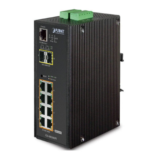
User’s Manual of IGS PoE series 2. INSTALLATION 2.1 Hardware Description The Industrial Managed PoE+ Switch provides three different running speeds – 10Mbps, 100Mbps and 1000Mbps and automatically distinguishes the speed of incoming connection. This section describes the hardware features of Industrial Managed PoE+ Switch. For easier management and control of the Industrial Managed PoE+ Switch, familiarize yourself with its display indicators and ports. - Page 25 User’s Manual of IGS PoE series IGS-10020HPT IGS-10020HPT Dimensions (W x D x H) : 72 x 107 x 152mm ...
- Page 26 User’s Manual of IGS PoE series IGS-20160HPT IGS-20160HPT Dimensions (W x D x H) : 84 x 107 x 152 mm ...
-
Page 27: Front Panel
User’s Manual of IGS PoE series 2.1.2 Front Panel IGS-10020PT IGS-10020HPT IGS-20160HPT Figure 2-1: IGS-10020PT Figure 2-2: IGS-10020HPT Figure 2-3:IGS-20160HPT Switch Front Panel Switch Front Panel Switch Front Panel ■ Gigabit TP Interface 10/100/1000BASE-T Copper, RJ45 Twisted-pair: Up to 100 meters. - Page 28 On the upper left side of the front panel, the reset button is designed for rebooting the Industrial Managed PoE+ Switch without turning off and on the power. The following is the summary table of reset button functions: IGS-10020PT/IGS-10020HPT IGS-20160HPT Figure 2-4:...
-
Page 29: Led Indications
User’s Manual of IGS PoE series 2.1.3 LED Indications IGS-10020PT IGS-10020HPT System Color Function Lights to indicate that the Switch has power. Green Lights to indicate that the Switch has power. Green Lights to indicate power failure. Fault Green Lights to indicate that the ERPS Ring has been created successfully. - Page 30 User’s Manual of IGS PoE series SFP 100/1000Mbps (Port-9, Port-10 mini-GBIC) Color Function Lights To indicate the link through that port is successfully established. LNK / ACT Green Blinks To indicate that the Switch is actively sending or receiving data over that port. Lights To indicate that the port is successfully connecting to the network at 1000Mbps.
- Page 31 User’s Manual of IGS PoE series IGS-20160HPT ■ System Color Function Lights to indicate power 1 has power. Green Lights to indicate power 2 has power. Green Lights to indicate power or port failure FAULT Green Lights to indicate that the ERPS Ring has been created successfully Ring Green Lights to indicate the switch has been enabled to Ring Owner...
- Page 32 User’s Manual of IGS PoE series ■ 10/100/1000BASE-T Interfaces (Port-17 to Port-18) Color Function Lights: To indicate the link through that port is successfully established at 1000Mbps. 1000 Green Blinks: To indicate that the switch is actively sending or receiving data over that port. LNK/ACT Lights: To indicate the link through that port is successfully established at 10/100Mbps.
-
Page 33: Switch Upper Panel
6 contacts. Please follow the steps below to insert the power wire. Insert positive/negative DC power wires into Contacts 1 and 2 for Power 1, or Contacts 5 and 6 for Power 2. IGS-10020PT: 48V~56V DC Figure 2-11: IGS-10020PT Upper Panel IGS-10020HPT: DC 12~48V Figure 2-12: IGS-10020HPT Upper Panel... - Page 34 Tighten the wire-clamp screws for preventing the wires from loosening. Power 1 Power 2 Positive (+) Pin Negative (-) Pin IGS-10020PT IGS-10020HPT Pin 1 / 5 Pin 2 / 6 IGS0-20160HPT The wire gauge for the terminal block should be in the range from 12 to 24 AWG.
-
Page 35: Wiring The Fault Alarm Contact
User’s Manual of IGS PoE series 2.1.5 Wiring the Fault Alarm Contact The fault alarm contacts are in the middle (3 & 4) of the terminal block connector as the picture shows below. Inserting the wires, the Industrial Managed PoE+ Switch will detect the fault status of the power failure, or port link failure (available for managed model). - Page 36 User’s Manual of IGS PoE series Tighten the wire-clamp screws for preventing the wires from loosening. DI1 DO0 DO1 GND GND Figure 2-15: 6-pin Terminal Block for DI and DO Wiring Input There are two Digital Input groups for you to monitor two different devices. The following topology shows how to wire DI0 and DI1.
- Page 37 User’s Manual of IGS PoE series Figure 2-17: Wiring DO0 and DO1 to Open Detector...
-
Page 38: Installing The Industrial Managed Poe+ Switch
User’s Manual of IGS PoE series 2.2 Installing the Industrial Managed PoE+ Switch This section describes how to install your Industrial Managed PoE+ Switch and make connections to the Industrial Managed PoE+ Switch. Please read the following topics and perform the procedures in the order being presented. To install your Industrial Managed PoE+ Switch on a desktop or shelf, simply complete the following steps. -
Page 39: Din-Rail Mounting
User’s Manual of IGS PoE series 2.2.2 DIN-rail Mounting This section describes how to install the Industrial Managed PoE+ Switch. There are two methods to install the Industrial Managed PoE+ Switch -- DIN-rail mounting and wall-mount plate mounting. Please read the following topics and perform the procedures in the order being presented. - Page 40 User’s Manual of IGS PoE series Step 3: Check whether the DIN-rail is tightly on the track. Please refer to the following procedures to remove the Industrial Managed PoE+ Switch from the track. Step 4: Lightly remove the DIN-rail from the track.
-
Page 41: Wall Mount Plate Mounting
User’s Manual of IGS PoE series 2.2.3 Wall Mount Plate Mounting To install the Industrial Managed PoE+ Switch on the wall, please follow the instructions below. Follow all the DIN-rail installation steps as shown in the example. Step 1: Remove the DIN-rail from the Industrial Managed PoE+ Switch. Use the screwdriver to loosen the screws to remove the DIN-rail. -
Page 42: Cabling
User’s Manual of IGS PoE series 2.3 Cabling 10/100/1000BASE-T All 10/100/1000BASE-T ports come with auto-negotiation capability. They automatically support 1000BASE-T, 100BASE-TX and 10BASE-T networks. Users only need to plug a working network device into one of the 10/100/1000BASE-T ports, and then turn on the Industrial Managed PoE+ Switch. The port will automatically run at 10Mbps, 20Mbps, 100Mbps or 200Mbps and 1000Mbps or 2000Mbps after negotiating with the connected device. -
Page 43: Installing The Sfp Transceiver
User’s Manual of IGS PoE series 2.3.1 Installing the SFP Transceiver The sections describe how to insert an SFP/SFP+ transceiver into an SFP/SFP+ slot. The SFP/SFP+ transceivers are hot-pluggable and hot-swappable. You can plug in and out the transceiver to/from any SFP/SFP+ port without having to power down the Industrial Managed PoE+ Switch as Figure 2-18 appears. - Page 44 User’s Manual of IGS PoE series Fast Ethernet Transceiver (100BASE-BX, Single Fiber Bi-directional SFP) Connector Model Speed (Mbps) Fiber Mode Distance Wavelength (TX) Wavelength (RX) Operating Temp. Interface 0 ~ 60 ℃ WDM(LC) Single Mode 20km 1310nm 1550nm MFB-FA20 MFB-FB20 0 ~ 60 ℃...
- Page 45 User’s Manual of IGS PoE series -40 ~ 75 ℃ MGB-TLA10(V2) 1000 WDM(LC) Single Mode 10km 1310nm 1550nm MGB-TLB10(V2) -40 ~ 75 ℃ 1000 WDM(LC) Single Mode 10km 1550nm 1310nm -40 ~ 75 ℃ MGB-TLA20 1000 WDM(LC) Single Mode 20km 1310nm 1550nm MGB-TLB20...
-
Page 46: Removing The Sfp/Sfp+ Transceiver
User’s Manual of IGS PoE series 2.3.2 Removing the SFP/SFP+ Transceiver Make sure there is no network activity by consulting or checking with the network administrator. Or through the management interface of the switch/converter (if available) to disable the port in advance. Remove the fiber optic cable gently. -
Page 47: Switch Management
User’s Manual of IGS PoE series 3. SWITCH MANAGEMENT This chapter explains the methods that you can use to configure management access to the Industrial Managed PoE+ Switch. It describes the types of management applications and the communication and management protocols that deliver data between your management device (workstation or personal computer) and the system. -
Page 48: Management Access Overview
User’s Manual of IGS PoE series 3.2 Management Access Overview The Industrial Managed PoE+ Switch gives you the flexibility to access and manage it using any or all of the following methods: Remote Telnet Interface Web browser Interface An external SNMP-based network management application ... -
Page 49: Cli Mode Management
Ethernet environment as long as you know the current IP address of the Industrial Managed PoE+ Switch. Note: 1. The following console screen is based on the IGS-10020HPT; the display of the IGS-10020HPT is the same as that of the IGS-10020PT/IGS-10020HPT/IGS-20160HPT. Direct Access... - Page 50 User’s Manual of IGS PoE series You can change these settings, if desired, after you log on. This management method is often preferred because you can remain connected and monitor the system during system reboots. Also, certain error messages are sent to the serial port, regardless of the interface through which the associated action was initiated.
-
Page 51: Web Management
Figure 3-3: Web Management Note: 1. The following console screen is based on the IGS-10020HPT; the display of the IGS-10020HPT is the same as that of the IGS-10020PT/IGS-10020HPT/IGS-20160HPT. You can then use your Web browser to list and manage the Industrial Managed PoE+ Switch configuration parameters from one central location;... -
Page 52: Snmp-Based Network Management
User’s Manual of IGS PoE series 3.5 SNMP-based Network Management You can use an external SNMP-based application to configure and manage the Industrial Managed PoE+ Switch, such as SNMP Network Manager, HP Openview Network Node Management (NNM) or What’s Up Gold. This management method requires the SNMP agent on the Industrial Managed PoE+ Switch and the SNMP Network Management Station to use the same community string. -
Page 53: Planet Smart Discovery Utility
User’s Manual of IGS PoE series 3.6 PLANET Smart Discovery Utility To easily list the Industrial Managed PoE+ Switch in your Ethernet environment, the Planet Smart Discovery Utility from user’s manual CD-ROM is an ideal solution. The following install instructions guide you to running the Planet Smart Discovery Utility. Open the Planet Smart Discovery Utility in administrator PC. - Page 54 User’s Manual of IGS PoE series This utility shows all the necessary information from the devices, such as MAC Address, Device Name, firmware version and Device IP Subnet address. A new password, IP Subnet address and description can be assigned to the devices. After setup is completed, press the “Update Device”, “Update Multi”...
-
Page 55: Web Configuration
User’s Manual of IGS PoE series 4. WEB CONFIGURATION This section introduces the configuration and functions of the Web-based management. About Web-based Management The Industrial Managed PoE+ Switch offers management features that allow users to manage the Industrial Managed PoE+ Switch from anywhere on the network through a standard browser such as Microsoft Internet Explorer. - Page 56 User’s Manual of IGS PoE series When the following login screen appears, please enter the default username "admin" with password “admin” (or the username/password you have changed via console) to login the main screen of Industrial Managed PoE+ Switch. The login screen in Figure 4-1-2 appears.
- Page 57 User’s Manual of IGS PoE series It is recommended to use Internet Explore 8.0 or above to access Industrial Managed PoE+ Switch. The changed IP address takes effect immediately after clicking on the Save button. From now on, you need to use the new IP address to access the Internet. For security reason, please change and memorize the new password after this first setup.
-
Page 58: Main Web Page
User’s Manual of IGS PoE series 4.1 Main Web page The Industrial Managed PoE+ Switch provides a Web-based browser interface for configuring and managing it. This interface allows you to access the Industrial Managed PoE+ Switch using the Web browser of your choice. This chapter describes how to use the Industrial Managed PoE+ Switch’s Web browser interface to configure and manage it. - Page 59 User’s Manual of IGS PoE series Main Menu Using the onboard web agent, you can define system parameters, manage and control the Industrial Managed PoE+ Switch, and all its ports, or monitor network conditions. Via the Web-Management, the administrator can set up the Industrial Managed PoE+ Switch by selecting the functions those listed in the Main Function.
-
Page 60: System
User’s Manual of IGS PoE series 4.2 System Use the System menu items to display and configure basic administrative details of the Industrial Managed PoE+ Switch. Under the System, the following topics are provided to configure and view the system information. This section has the following items: The Industrial Managed PoE+ Switch system information is provided here. -
Page 61: Management
User’s Manual of IGS PoE series 4.2.1 Management 4.2.1.1 System Information The System Infomation page provides information for the current device information. System Information page helps a switch administrator to identify the hardware MAC address, software version and system uptime. The screen in Figure 4-2-1 appears. -
Page 62: Ip Configuration
User’s Manual of IGS PoE series : Click to refresh the page; any changes made locally will be undone. 4.2.1.2 IP Configuration The IP Configuration includes the IP Configuration, IP Interface and IP Routes. The configured column is used to view or change the IP configuration. The maximum number of interfaces supported is 128 and the maximum number of routes is 32. - Page 63 User’s Manual of IGS PoE series reachable (e.g. via PING) for activating DNS service. Configured IPv6 Explicitly provide the valid IPv6 unicast (except linklocal) address of the DNS Server. Make sure the configured DNS server could be reachable (e.g. via PING6) for activating DNS service. ...
- Page 64 User’s Manual of IGS PoE series DHCP fallback address is desired. The IPv4 network mask, in number of bits (prefix length). Valid values Mask Length are between 0 and 30 bits for a IPv4 address. If DHCP is enabled, this field configures the fallback address network mask.
-
Page 65: Ip Status
User’s Manual of IGS PoE series notation or a valid IPv6 notation. Gateway and Network must be of the same type. The VLAN ID (VID) of the specific IPv6 interface associated with the Next Hop VLAN gateway. The given VID ranges from 1 to 4095 and will be effective only when the corresponding IPv6 interface is valid. -
Page 66: Users Configuration
User’s Manual of IGS PoE series The page includes the following fields: Object Description The name of the interface. • IP Interfaces Interface The address type of the entry. This may be LINK or IPv4. Type The current address of the interface (of the given type). Address The status flags of the interface (and/or address). - Page 67 User’s Manual of IGS PoE series By default setting, most groups privilege level 5 has the read-only access and privilege level 10 has the read-write access. And the system maintenance (software upload, factory defaults and etc.) needs user privilege level 15. Generally, the privilege level 15 can be used for an administrator account, privilege level 10 for a standard user account and privilege level 5 for a guest account.
- Page 68 User’s Manual of IGS PoE series By default setting, most groups privilege level 5 has the read-only access and privilege level 10 has the read-write access. And the system maintenance (software upload, factory defaults and etc.) needs user privilege level 15. Generally, the privilege level 15 can be used for an administrator account, privilege level 10 for a standard user account and privilege level 5 for a guest account.
-
Page 69: Privilege Levels
User’s Manual of IGS PoE series 4.2.1.5 Privilege Levels This page provides an overview of the privilege levels. After setup is completed, please press the “Apply” button to take effect. Please login web interface with new user name and password and the screen in Figure 4-2-7 appears. - Page 70 User’s Manual of IGS PoE series Security: Authentication, System Access Management, Port (contains Dot1x port, MAC based and the MAC Address Limit), ACL, HTTPS, SSH, ARP Inspection and IP source guard. IP: Everything except 'ping'. Port: Everything except 'VeriPHY'. ...
-
Page 71: Ntp Configuration
User’s Manual of IGS PoE series 4.2.1.6 NTP Configuration Configure NTP on this page. NTP is an acronym for Network Time Protocol, a network protocol for synchronizing the clocks of computer systems. NTP uses UDP (data grams) as transport layer. You can specify NTP Servers. The NTP Configuration screen in Figure 4-2-8 appears. -
Page 72: System Time Correction Manually
User’s Manual of IGS PoE series 4.2.1.6.1 System Time Correction Manually Configure NTP on this page. NTP is an acronym for Network Time Protocol, a network protocol for synchronizing the clocks of computer systems. NTP uses UDP (data grams) as transport layer. You can specify NTP Servers. The NTP Configuration screen in Figure 4-2-9 appears. -
Page 73: Time Configuration
User’s Manual of IGS PoE series 4.2.1.7 Time Configuration Configure Time Zone on this page. A Time Zone is a region that has a uniform standard time for legal, commercial, and social purposes. It is convenient for areas in close commercial or other communication to keep the same time, so time zones tend to follow the boundaries of countries and their subdivisions. -
Page 74: Upnp
User’s Manual of IGS PoE series Enter the number of minutes to add during Daylight Saving Time. ( Range: 1 to • Offset Settings 1440 ) Buttons : Click to apply changes. : Click to undo any changes made locally and revert to previously saved values. 4.2.1.8 UPnP Configure UPnP on this page. - Page 75 User’s Manual of IGS PoE series done at less than one-half of the advertising duration. In the implementation, the switch sends SSDP messages periodically at the interval one-half of the advertising duration minus 30 seconds. Valid values are in the range 100 to 86400.
-
Page 76: Dhcp Relay
User’s Manual of IGS PoE series 4.2.1.9 DHCP Relay Configure DHCP Relay on this page. DHCP Relay is used to forward and transfer DHCP messages between the clients and the server when they are not on the same subnet domain. The DHCP option 82 enables a DHCP relay agent to insert specific information into a DHCP request packets when forwarding client DHCP packets to a DHCP server and remove the specific information from a DHCP reply packets when forwarding server DHCP packets to a DHCP client. - Page 77 User’s Manual of IGS PoE series Indicates the DHCP relay information mode option operation. Possible modes • Relay Information are: Mode Enabled: Enable DHCP relay information mode operation. When enabling DHCP relay information mode operation, the agent inserts specific information (option82) into a DHCP message when forwarding to DHCP server and removing it from a DHCP message when transferring to DHCP client.
-
Page 78: Dhcp Relay Statistics
User’s Manual of IGS PoE series 4.2.1.10 DHCP Relay Statistics This page provides statistics for DHCP relay. The DHCP Relay Statistics screen in Figure 4-2-13 appears. Figure 4-2-13: DHCP Relay Statistics Page Screenshot The page includes the following fields: Server Statistics Object Description The packets number that relayed from client to server. - Page 79 User’s Manual of IGS PoE series Client Statistics Object Description The packets number that relayed packets from server to client. • Transmit to Client The packets number that erroneously sent packets to servers. • Transmit Error The packets number that received packets from server. •...
-
Page 80: Cpu Load
User’s Manual of IGS PoE series 4.2.1.11 CPU Load This page displays the CPU load, using an SVG graph. The load is measured as average over the last 100ms, 1 sec and 10 seconds intervals. The last 120 samples are graphed, and the last numbers are displayed as text as well. In order to display the SVG graph, your browser must support the SVG format. -
Page 81: System Log
User’s Manual of IGS PoE series 4.2.1.12 System Log The Industrial Managed PoE+ Switch system log information is provided here. The System Log screen in Figure 4-2-15 appears. Figure 4-2-15: System Log Page Screenshot The page includes the following fields: Object Description The ID (>= 1) of the system log entry. -
Page 82: Detailed Log
User’s Manual of IGS PoE series : Updates the system log entries, starting from the first available entry ID. : Updates the system log entries, ending at the last entry currently displayed. : Updates the system log entries, starting from the last entry currently displayed. : Updates the system log entries, ending at the last available entry ID. -
Page 83: Remote Syslog
User’s Manual of IGS PoE series 4.2.1.14 Remote Syslog Configure remote syslog on this page. The Remote Syslog screen in Figure 4-2-17 appears. Figure 4-2-17: Remote Syslog Page Screenshot The page includes the following fields: Object Description Indicates the server mode operation. When the mode operation is enabled, the •... -
Page 84: Smtp Configuration
User’s Manual of IGS PoE series 4.2.1.15 SMTP Configuration This page facilitates an SMTP Configuration on the switch. The SMTP Configure screen in Figure 4-2-18 appears. Figure 4-2-18: SMTP Configuration Page Screenshot The page includes the following fields: Object Description Controls whether SMTP is enabled on this switch. -
Page 85: Fault Alarm
User’s Manual of IGS PoE series Buttons : Send a test mail to mail server to check whether this account is available or not. : Click to save changes. : Click to undo any changes made locally and revert to previously saved values. 4.2.1.16 Fault Alarm This page facilitates an update of the firmware controlling the switch. -
Page 86: Digital Input/Output
User’s Manual of IGS PoE series 4.2.1.17 Digital Input/Output Digital Input allows user to log external device (such as industrial cooler) dead or alive or something else. System will log a user customized message into system log and syslog, and issue SNMP trap or issue an alarm E-mail. Digital Output allows user to monitor the switch port and power, and let system issue a high or low signal to an external device (such as alarm) when the monitor port or power has failed. - Page 87 User’s Manual of IGS PoE series Allows user to record alarm message to System log, syslog or issues out via SNMP Trap or SMTP. As default SNMP Trap and SMTP are disabled, please enable them first if you want to issue alarm message via them. As Digital Output: Allows user to monitor an alarm from port failure, power failure, Digital Input 0 (DI 0) and Digital Input 1(DI 1) which means if Digital Output has detected...
-
Page 88: Simple Network Management Protocol
User’s Manual of IGS PoE series 4.2.2 Simple Network Management Protocol 4.2.2.1 SNMP Overview The Simple Network Management Protocol (SNMP) is an application layer protocol that facilitates the exchange of management information between network devices. It is part of the Transmission Control Protocol/Internet Protocol (TCP/IP) protocol suite. SNMP enables network administrators to manage network performance, find and solve network problems, and plan for network growth. -
Page 89: Snmp System Configuration
User’s Manual of IGS PoE series Write = private 。 Read = public 。 Use the SNMP Menu to display or configure the Industrial Managed PoE+ Switch 's SNMP function. This section has the following items: Configure SNMP on this page. ... - Page 90 User’s Manual of IGS PoE series The allowed string length is 0 to 255, and the allowed content is the ASCII characters from 33 to 126. The field is applicable only when SNMP version is SNMPv1 or SNMPv2c. If SNMP version is SNMPv3, the community string will be associated with SNMPv3 communities table.
-
Page 91: Snmp Trap Configuration
User’s Manual of IGS PoE series 4.2.2.3 SNMP Trap Configuration Configure SNMP trap on this page. The SNMP Trap Configuration screen in Figure 4-2-2-3 appears. Figure 4-2-2-3: SNMP Trap Configuration Page Screenshot The page includes the following fields: Object Description Indicates which trap Configuration's name for configuring. - Page 92 User’s Manual of IGS PoE series Indicates the SNMP trap inform mode operation. Possible modes are: • Trap Inform Mode Enabled: Enable SNMP trap authentication failure. Disabled: Disable SNMP trap authentication failure. Indicates the SNMP trap inform timeout. •...
-
Page 93: Snmp System Information
User’s Manual of IGS PoE series 4.2.2.4 SNMP System Information The switch system information is provided here. The SNMP System Information screen in Figure 4-2-2-4 appears. Figure 4-2-2-4: System Information Configuration Page Screenshot The page includes the following fields: Object Description The textual identification of the contact person for this managed node, together •... - Page 94 User’s Manual of IGS PoE series The page includes the following fields: Object Description Check to delete the entry. It will be deleted during the next save. • Delete Indicates the community access string to permit access to SNMPv3 agent. The •...
-
Page 95: Snmpv3 Users
User’s Manual of IGS PoE series 4.2.2.6 SNMPv3 Users Configure SNMPv3 users table on this page. The entry index keys are Engine ID and User Name. The SNMPv3 Users screen in Figure 4-2-2-6 appears. Figure 4-2-2-6: SNMPv3 Users Configuration Page Screenshot The page includes the following fields: Object Description... -
Page 96: Snmpv3 Groups
User’s Manual of IGS PoE series protocol. SHA: An optional flag to indicate that this user using SHA authentication protocol. The value of security level cannot be modified if entry already exist. That means must first ensure that the value is set correctly. A string identifying the authentication pass phrase. -
Page 97: Snmpv3 Views
User’s Manual of IGS PoE series The page includes the following fields: Object Description Check to delete the entry. It will be deleted during the next save. • Delete Indicates the security model that this entry should belong to. Possible security •... -
Page 98: Snmpv3 Access
User’s Manual of IGS PoE series The page includes the following fields: Object Description Check to delete the entry. It will be deleted during the next save. • Delete A string identifying the view name that this entry should belong to. The allowed •... - Page 99 User’s Manual of IGS PoE series The page includes the following fields: Object Description Check to delete the entry. It will be deleted during the next save. • Delete A string identifying the group name that this entry should belong to. The allowed •...
-
Page 100: Rmon
User’s Manual of IGS PoE series 4.2.3 RMON RMON is the most important expansion of the standard SNMP. RMON is a set of MIB definitions, used to define standard network monitor functions and interfaces, enabling the communication between SNMP management terminals and remote monitors. - Page 101 User’s Manual of IGS PoE series protocol. InNUcastPkts: The number of broadcast and multi-cast packets delivered to a higher-layer protocol. InDiscards: The number of inbound packets that are discarded even the packets are normal. InErrors: The number of inbound packets that contains errors preventing ...
-
Page 102: Rmon Alarm Status
User’s Manual of IGS PoE series Click to undo any changes made locally and revert to previously saved values. 4.2.3.2 RMON Alarm Status This page provides an overview of RMON Alarm entries. Each page shows up to 99 entries from the Alarm table, default being 20, selected through the "entries per page"... -
Page 103: Rmon Event Configuration
User’s Manual of IGS PoE series : Updates the table, starting with the entry after the last entry currently displayed. 4.2.3.3 RMON Event Configuration Configure RMON Event table on this page. The entry index key is ID; screen in Figure 4-2-3-3 appears. -
Page 104: Rmon Event Status
User’s Manual of IGS PoE series 4.2.3.4 RMON Event Status This page provides an overview of RMON Event table entries. Each page shows up to 99 entries from the Event table, default being 20, selected through the "entries per page" input field. When first visited, the web page will show the first 20 entries from the beginning of the Event table. -
Page 105: Rmon History Configuration
User’s Manual of IGS PoE series 4.2.3.5 RMON History Configuration Configure RMON History table on this page. The entry index key is ID; screen in Figure 4-2-3-5 appears. Figure 4-2-3-5: RMON History Configuration Page Screenshot The page includes the following fields: Object Description Check to delete the entry. -
Page 106: Rmon History Status
User’s Manual of IGS PoE series 4.2.3.6 RMON History Status This page provides an detail of RMON history entries; screen in Figure 4-2-3-6 appears. Figure 4-2-3-6: RMON History Overview Page Screenshot The page includes the following fields: Object Description • History Index Indicates the index of History control entry. -
Page 107: Rmon Statistics Configuration
User’s Manual of IGS PoE series The best estimate of the mean physical layer network utilization on this interface • Utilization during this sampling interval, in hundredths of a percent. Buttons : Click to refresh the page immediately. Auto-refresh Check this box to refresh the page automatically. Automatic refresh occurs every 3 seconds. Updates the table, starting from the first entry in the History table, i.e., the entry with the lowest History Index and Sample Index : Updates the table, starting with the entry after the last entry currently displayed. -
Page 108: Rmon Statistics Status
User’s Manual of IGS PoE series 4.2.3.8 RMON Statistics Status This page provides an overview of RMON Statistics entries. Each page shows up to 99 entries from the Statistics table, default being 20, selected through the "entries per page" input field. When first visited, the web page will show the first 20 entries from the beginning of the Statistics table. - Page 109 User’s Manual of IGS PoE series The total number of packets (including bad packets) received that were 64 octets • 64 Bytes in length. The total number of packets (including bad packets) received that were between • 65~127 65 to 127 octets in length. The total number of packets (including bad packets) received that were between •...
-
Page 110: Dhcp Server
User’s Manual of IGS PoE series 4.2.4 DHCP server 4.2.4.1 DHCP Server Mode Configuration Configure DHCP server mode on this page. The entry index key is ID.; screen in Figure 4-2-4-1 appears. Figure 4-2-4-1: DHCP server mode Page Screenshot The page includes the following fields: Object Description Configure the operation mode per system. -
Page 111: Dhcp Server Excluded Ip Configuration
User’s Manual of IGS PoE series • Mode Indicate the operation mode per VLAN. Possible modes are: Enabled: Enable DHCP server per VLAN. Disabled: Disable DHCP server pre VLAN. Buttons : Click to add a new VLAN range. : Click to apply changes Click to undo any changes made locally and revert to previously saved values. -
Page 112: Dhcp Server Pool Configuration
User’s Manual of IGS PoE series 4.2.4.3 DHCP Server pool Configuration This page manages DHCP pools. According to the DHCP pool, DHCP server will allocate IP address and deliver configuration parameters to DHCP client. screen in Figure 4-2-4-3 appears. Figure 4-2-4-3: DHCP server pool Page Screenshot The page includes the following fields: Object Description... -
Page 113: Dhcp Server Pool Configuration
User’s Manual of IGS PoE series Click to undo any changes made locally and revert to previously saved values. 4.2.4.4 DHCP Server pool Configuration This page displays the database counters and the number of DHCP messages sent and received by DHCP server. screen in Figure 4-2-4-4 appears. -
Page 114: Dhcp Server Binding Ip Configuration
User’s Manual of IGS PoE series the pool is of host type. Number of bindings that their lease time expired or they are cleared from • Expired Binding Automatic/Manual type bindings. DHCP message Received Counters Object Description Number of DHCP DISCOVER messages received. •... -
Page 115: Dhcp Server Declined Ip
User’s Manual of IGS PoE series The page includes the following fields: Object Description Display IP address allocated to DHCP client. • IP Display type of binding. Possible types are Automatic, Manual, Expired. • Type Display state of binding. Possible states are Committed, Allocated, Expired •... -
Page 116: Dhcp Detail Statistics
User’s Manual of IGS PoE series The page includes the following fields: Object Description Display List of IP addresses declined. • Delined IP Buttons : Check this box to refresh the page automatically Click to refresh the page immediately. 4.2.4.7 DHCP Detail Statistics This page provides statistics for DHCP snooping. - Page 117 User’s Manual of IGS PoE series The page includes the following fields: Object Description Display the number of discover (option 53 with value 1) packets received and • Rx and Tx Discover transmitted. Display the number of offer (option 53 with value 2) packets received and •...
-
Page 118: Industrial Protocol
User’s Manual of IGS PoE series 4.2.5 Industrial Protocol With the supported Modbus TCP/IP protocol, the IGS-5225 series can easily integrate with SCADA systems, HMI systems and other data acquisition systems in factory floors. It enable administrators to remotely monitor the industrial Ethernet switch’s operating information, port information and communication status, thus easily achieving enhanced monitoring and maintenance of the entire factory. -
Page 119: Switching
User’s Manual of IGS PoE series 4.3 Switching 4.3.1 Port Management Use the Port Menu to display or configure the Industrial Managed PoE+ Switch's ports. This section has the following items: Configures port connection settings Port Configuration Lists Ethernet and RMON port statistics ... - Page 120 User’s Manual of IGS PoE series Select any available link speed for the given switch port. Draw the menu bar to • Configured Link Speed select the mode. Auto – Set up Auto negotiation for copper interface. 10Mbps HDX - Force sets 10Mbps/Half-Duplex mode. ...
-
Page 121: Port Statistics Overview
User’s Manual of IGS PoE series 4.3.1.2 Port Statistics Overview This page provides an overview of general traffic statistics for all switch ports. The Port Statistics Overview screen in Figure 4-3-1-2 appears. Figure 4-3-1-2: Port Statistics Overview Page Screenshot The displayed counters are: Object Description The logical port for the settings contained in the same row. - Page 122 User’s Manual of IGS PoE series error counters for receive and transmit. The Detailed Port Statistics screen in Figure 4-3-1-3 appears. Figure 4-3-1-3: Detailed Port Statistics Port 1 Page Screenshot The page includes the following fields: Receive Total and Transmit Total Object Description The number of received and transmitted (good and bad) packets...
-
Page 123: Sfp Module Information
User’s Manual of IGS PoE series Receive and Transmit Queue Counters The number of received and transmitted packets per input and output queue. Receive Error Counters Object Description The number of frames dropped due to lack of receive buffers or egress •... - Page 124 User’s Manual of IGS PoE series power, temperature, laser bias current and transceiver supply voltage in real time. You can also use the hyperlink of port no. to check the statistics on a specific interface. The SFP Module Information screen in Figure 4-3-1-4 appears.
-
Page 125: Port Mirror
User’s Manual of IGS PoE series from the SFP DDM module. – SFP DDM Module Only Buttons SFP Monitor Event Alert: send trap Warning Temperature: degrees C Check SFP Monitor Event Alert box; it will be in accordance with your warning temperature setting and allows users to record message out via SNMP Trap. - Page 126 User’s Manual of IGS PoE series The traffic to be copied to the mirror port is selected as follows: All frames received on a given port (also known as ingress or source mirroring). • All frames transmitted on a given port (also known as egress or destination mirroring). •...
- Page 127 User’s Manual of IGS PoE series The page includes the following fields: Object Description Select session id to configure. • Session To Enabled/Disabled the mirror or Remote Mirroring function • Mode • Type Mirror The switch is running on mirror mode. source port(s) destination port are located on this switch.
- Page 128 User’s Manual of IGS PoE series The destination port is a switched port that you receive a copy of traffic from the source port. For a given port, a frame is only transmitted once. It is therefore not possible to mirror Tx frames on the mirror port.
-
Page 129: Link Aggregation
User’s Manual of IGS PoE series 4.3.2 Link Aggregation Port Aggregation optimizes port usage by linking a group of ports together to form a single Link Aggregated Groups (LAGs). Port Aggregation multiplies the bandwidth between the devices, increases port flexibility, and provides link redundancy. Each LAG is composed of ports of the same speed, set to full-duplex operations. - Page 130 User’s Manual of IGS PoE series The Link Aggregation Control Protocol (LACP) provides a standardized means for exchanging information between Partner Systems that require high speed redundant links. Link aggregation lets you group up to eight consecutive ports into a single dedicated connection.
-
Page 131: Static Aggregation
User’s Manual of IGS PoE series 4.3.2.1 Static Aggregation This page is used to configure the Aggregation hash mode and the aggregation group. The aggregation hash mode settings are global. Hash Code Contributors The Static Aggregation screen in Figure 4-3-2-2 appears. -
Page 132: Static Aggregation Status
User’s Manual of IGS PoE series Figure 4-3-2-3: Aggregation Group Configuration Page Screenshot The page includes the following fields: .Object Description Indicates the group ID for the settings contained in the same row. Group ID • Group ID "Normal" indicates there is no aggregation. Only one group ID is valid per port. Each switch port is listed for each group ID. -
Page 133: Lacp Configuration
User’s Manual of IGS PoE series The page includes the following fields: Object Description Display the Aggregation ID associated with this aggregation instance. • Aggr ID Display the Name of the Aggregation group ID. • Name Display the type of the Aggregation group(Static or LACP). •... - Page 134 User’s Manual of IGS PoE series Figure 4-3-2-5 : LACP Port Configuration Page Screenshot The page includes the following fields: Object Description The switch port number. • Port • Controls whether LACP is enabled on this switch port. LACP will form an LACP Enabled aggregation when 2 or more ports are connected to the same partner.
-
Page 135: Lacp System Status
User’s Manual of IGS PoE series LACP packet. The Priority controls the priority of the port. If the LACP partner wants to form a • Priority larger group than is supported by this device then this parameter will control which ports will be active and which ports will be in a backup role. Lower number means greater priority. -
Page 136: Lacp Port Status
User’s Manual of IGS PoE series 4.3.2.5 LACP Port Status This page provides a status overview of LACP status for all ports. The LACP Port Status screen in Figure 4-5-2-7 appears. Figure 4-3-2-7: LACP Status Page Screenshot The page includes the following fields: Object Description The switch port number. -
Page 137: Lacp Port Statistics
User’s Manual of IGS PoE series 4.3.2.6 LACP Port Statistics This page provides an overview for LACP statistics for all ports. The LACP Port Status screen in Figure 4-5-2-8 appears. Figure 4-3-2-8: LACP Port Statistics Page Screenshot The page includes the following fields: Object Description The switch port number. -
Page 138: Vlan
User’s Manual of IGS PoE series 4.3.3 VLAN 4.3.3.1 VLAN Overview A Virtual Local Area Network (VLAN) is a network topology configured according to a logical scheme rather than the physical layout. VLAN can be used to combine any collection of LAN segments into an autonomous user group that appears as a single LAN. -
Page 139: Ieee 802.1Q Vlan
User’s Manual of IGS PoE series 4.3.3.2 IEEE 802.1Q VLAN In large networks, routers are used to isolate broadcast traffic for each subnet into separate domains. This Industrial Managed PoE+ Switch provides a similar service at Layer 2 by using VLANs to organize any group of network nodes into separate broadcast domains. - Page 140 User’s Manual of IGS PoE series ■ 802.1Q VLAN Tags The figure below shows the 802.1Q VLAN tag. There are four additional octets inserted after the source MAC address. Their presence is indicated by a value of 0x8100 in the Ether Type field. When a packet's Ether Type field is equal to 0x8100, the packet carries the IEEE 802.1Q/802.1p tag.
- Page 141 User’s Manual of IGS PoE series Every physical port on a switch has a PVID. 802.1Q ports are also assigned a PVID, for use within the switch. If no VLAN are defined on the switch, all ports are then assigned to a default VLAN with a PVID equal to 1. Untagged packets are assigned the PVID of the port on which they were received.
-
Page 142: Vlan Port Configuration
User’s Manual of IGS PoE series ■ Port Overlapping Port overlapping can be used to allow access to commonly shared network resources among different VLAN groups, such as file servers or printers. Note that if you implement VLANs which do not overlap, but still need to communicate, you can connect them by enabled routing on this switch. - Page 143 User’s Manual of IGS PoE series ■ IEEE 802.1Q Tunneling (Q-in-Q) IEEE 802.1Q Tunneling (Q-in-Q) is designed for service providers carrying traffic for multiple customers across their networks. Q-in-Q tunneling is used to maintain customer-specific VLAN and Layer 2 protocol configurations even when different customers use the same internal VLAN IDs.
- Page 144 User’s Manual of IGS PoE series Global VLAN Configuration The Global VLAN Configuration screen in Figure 4-3-3-1 appears. Figure 4-3-3-1 : Global VLAN Configuration Screenshot The page includes the following fields: Object Description This field shows the allowed Access VLANs, it only affects ports configured as •...
- Page 145 User’s Manual of IGS PoE series The page includes the following fields: Object Description This is the logical port number for this row. • Port Access ports are normally used to connect to end stations. Dynamic features like • Mode Access Voice VLAN may add the port to more VLANs behind the scenes.
- Page 146 User’s Manual of IGS PoE series The Port VLAN is called an "Access VLAN" for ports in Access mode and Native VLAN for ports in Trunk or Hybrid mode. Ports in hybrid mode allow for changing the port type, that is, whether a frame's •...
-
Page 147: Vlan Membership Status
User’s Manual of IGS PoE series Only untagged frames are accepted on ingress. Tagged frames are discarded. This option is only available for ports in Hybrid mode. Ports in Trunk and Hybrid Egress Tagging mode may control the tagging of frames on egress. ■... - Page 148 User’s Manual of IGS PoE series Figure 4-3-3-3: VLAN Membership Status for Static User Page Screenshot The page includes the following fields: Object Description A VLAN User is a module that uses services of the VLAN management • VLAN User functionality to configure VLAN memberships and VLAN port configuration such as PVID, UVID.
-
Page 149: Vlan Port Status
User’s Manual of IGS PoE series Buttons : Select VLAN Users from this drop down list. Auto-refresh : Check this box to refresh the page automatically. Automatic refresh occurs every 3 seconds. : Click to refresh the page immediately. : Updates the table starting from the first entry in the VLAN Table, i.e. the entry with the lowest VLAN ID. : Updates the table, starting with the entry after the last entry currently displayed. -
Page 150: Private Vlan
User’s Manual of IGS PoE series the classified VLAN of the frame, the frame is discarded. Shows whether the port accepts all frames or only tagged frames. This • Frame Type parameter affects VLAN ingress processing. If the port only accepts tagged frames, untagged frames received on that port are discarded. - Page 151 User’s Manual of IGS PoE series Figure 4-3-3-5: Private VLAN Membership Configuration page screenshot The page includes the following fields: Object Description To delete a private VLAN entry, check this box. The entry will be deleted during • Delete the next save. Indicates the ID of this particular private VLAN.
-
Page 152: Port Isolation
User’s Manual of IGS PoE series 4.3.3.7 Port Isolation Overview When a VLAN is configured to be a private VLAN, communication between ports within that VLAN can be prevented. Two application examples are provided in this section: • Customers connected to an ISP can be members of the same VLAN, but they are not allowed to communicate with each other within that VLAN. - Page 153 User’s Manual of IGS PoE series The configuration of promiscuous and isolated ports applies to all private VLANs. When traffic comes in on a promiscuous port in a private VLAN, the VLAN mask from the VLAN table is applied. When traffic comes in on an isolated port, the private VLAN mask is applied in addition to the VLAN mask from the VLAN table.
-
Page 154: Vlan Setting Example
User’s Manual of IGS PoE series 4.3.3.8 VLAN setting example: Separate VLAN 802.1Q VLAN Trunk Port Isolate 4.3.3.8.1 Two Separate 802.1Q VLANs The diagram shows how the Industrial Managed PoE+ Switch handle Tagged and Untagged traffic flow for two VLANs. VLAN Group 2 and VLAN Group 3 are separated VLAN. - Page 155 User’s Manual of IGS PoE series While [PC-1] transmit an untagged packet enters Port-1, the Industrial Managed PoE+ Switch will tag it with a VLAN Tag=2. [PC-2] and [PC-3] will received the packet through Port-2 and Port-3. [PC-4],[PC-5] and [PC-6] received no packet. While the packet leaves Port-2, it will be stripped away it tag becoming an untagged packet.
-
Page 156: Vlan Trunking Between Two 802.1Q Aware Switches
User’s Manual of IGS PoE series Figure 4-3-3-9: Change Port VLAN of Port 1~3 to be VLAN2 and Port VLAN of Port 4~6 to be VLAN3 Enable VLAN Tag for specific ports Link Type: Port-3 (VLAN-2) and Port-6 (VLAN-3) Change Port 3 Mode as Trunk, Selects Egress Tagging as Tag All and Types 2 in the Allowed VLANs column. Change Port 6 Mode as Trunk and Selects Egress Tagging as Tag All and Types 3 in the Allowed VLANs column. - Page 157 User’s Manual of IGS PoE series Figure 4-3-3-11: VLAN Trunking Diagram Setup steps Add VLAN Group Add two VLANs – VLAN 2 and VLAN 3 Type 1-3 in Allowed Access VLANs column, the 1-3 is including VLAN1 and 2 and 3. Figure 4-3-3-12: Add VLAN 2 and VLAN 3 Assign VLAN Member and PVID for each port : VLAN 2 : Port-1,Port-2 and Port-3...
- Page 158 User’s Manual of IGS PoE series Figure 4-3-3-13: Changes Port VLAN of Port 1~3 to be VLAN2 and Port VLAN of Port 4~6 to be VLAN3 For the VLAN ports connecting to the hosts, please refer to 4.6.10.1 examples. The following steps will focus on the VLAN Trunk port configuration.
-
Page 159: Port Isolate
User’s Manual of IGS PoE series That is, although the VLAN 2 members: Port-1 to Port-3 and VLAN 3 members: Port-4 to Port-6 also belongs to VLAN 1. But with different PVID settings, packets form VLAN 2 or VLAN 3 is not able to access to the other VLAN. Repeat Steps 1 to 6, set up the VLAN Trunk port at the partner switch and add more VLANs to join the VLAN trunk, repeat Steps 1 to 3 to assign the Trunk port to the VLANs. -
Page 160: Mac-Based Vlan
User’s Manual of IGS PoE series 4.3.3.9 MAC-based VLAN The MAC-based VLAN entries can be configured here. This page allows for adding and deleting MAC-based VLAN entries and assigning the entries to different ports. This page shows only static entries. The MAC-based VLAN screen in Figure 4-3-3-16 appears. -
Page 161: Ip Subnet-Based Vlan Membership Configuration
User’s Manual of IGS PoE series : Click to apply changes : Click to undo any changes made locally and revert to previously saved values. Auto-refresh : Check this box to refresh the page automatically. Automatic refresh occurs every 3 seconds. : Click to refresh the page immediately. -
Page 162: Protocol-Based Vlan
User’s Manual of IGS PoE series default, no ports are members and all boxes are unchecked. Click to add a new IP subnet to VLAN ID mapping entry. An empty row is added • Adding a New IP to the table, and the mapping can be configured as needed. Any IP subnet-based VLAN address/mask can be configured for the mapping. - Page 163 User’s Manual of IGS PoE series Ethernet SNAP Note: On changing the Frame type field, valid value of the following text field will vary depending on the new frame type you selected. Valid value that can be entered in this text field depends on the option selected •...
-
Page 164: Protocol-Based Vlan Membership
User’s Manual of IGS PoE series Buttons : Click to add a new entry in mapping table. : Click to apply changes : Click to undo any changes made locally and revert to previously saved values. Auto-refresh : Check this box to refresh the page automatically. Automatic refresh occurs every 3 seconds. : Click to refresh the page immediately. - Page 165 User’s Manual of IGS PoE series added to the table, the Group Name, VLAN ID and port members can be VLAN mapping entry configured as needed. Legal values for a VLAN ID are 1 through 4095. The “Delete” button can be used to undo the addition of new entry. Buttons : Click to apply changes : Click to undo any changes made locally and revert to previously saved values.
-
Page 166: Spanning Tree Protocol
User’s Manual of IGS PoE series 4.3.4 Spanning Tree Protocol 4.3.4.1 Theory The Spanning Tree protocol can be used to detect and disable network loops, and to provide backup links between switches, bridges or routers. This allows the switch to interact with other bridging devices in your network to ensure that only one route exists between any two stations on the network, and provide backup links which automatically take over when a primary link goes down. - Page 167 User’s Manual of IGS PoE series The path cost to the root from the transmitting port The port identifier of the transmitting port The switch sends BPDUs to communicate and construct the spanning-tree topology. All switches connected to the LAN on which the packet is transmitted will receive the BPDU.
- Page 168 User’s Manual of IGS PoE series From forwarding to disabled From disabled to blocking Figure 4-3-4-1: STP Port State Transitions You can modify each port state by using management software. When you enable STP, every port on every switch in the network goes through the blocking state and then transitions through the states of listening and learning at power up.
- Page 169 User’s Manual of IGS PoE series The following are the user-configurable STP parameters for the switch level: Parameter Description Default Value A combination of the User-set priority and 32768 + MAC Bridge Identifier(Not user the switch’s MAC address. configurable The Bridge Identifier consists of two parts: except by setting priority a 16-bit priority and a 48-bit Ethernet MAC below)
- Page 170 User’s Manual of IGS PoE series User-Changeable STA Parameters The Switch’s factory default setting should cover the majority of installations. However, it is advisable to keep the default settings as set at the factory; unless, it is absolutely necessary. The user changeable parameters in the Switch are as follows: Priority –...
- Page 171 User’s Manual of IGS PoE series Figure 4-3-4-2: Before Applying the STA Rules In this example, only the default STP values are used. Figure 4-3-4-3: After Applying the STA Rules...
-
Page 172: Stp System Configuration
User’s Manual of IGS PoE series The switch with the lowest Bridge ID (switch C) was elected the root bridge, and the ports were selected to give a high port cost between switches B and C. The two (optional) Gigabit ports (default port cost = 20,000) on switch A are connected to one (optional) Gigabit port on both switch B and C. - Page 173 User’s Manual of IGS PoE series The page includes the following fields: Basic Settings Object Description The STP protocol version setting. Valid values are: • Protocol Version STP (IEEE 802.1D Spanning Tree Protocol) RSTP (IEEE 802.2w Rapid Spanning Tree Protocol) ...
-
Page 174: Bridge Status
User’s Manual of IGS PoE series removed from the active topology. Control whether a port in the error-disabled state automatically will be enabled • Port Error Recovery after a certain time. If recovery is not enabled, ports have to be disabled and re-enabled for normal STP operation. -
Page 175: Cist Port Configuration
User’s Manual of IGS PoE series Root Path Cost. For the Root Bridge this is zero. For all other Bridges, it is the • Root Cost sum of the Port Path Costs on the least cost path to the Root Bridge. The current state of the Topology Change Flag for this Bridge instance. - Page 176 User’s Manual of IGS PoE series The page includes the following fields: Object Description The switch port number of the logical STP port. • Port Controls whether RSTP is enabled on this switch port. • STP Enabled Controls the path cost incurred by the port. The Auto setting will set the path cost •...
- Page 177 User’s Manual of IGS PoE series Controls whether the port connects to a point-to-point LAN rather than a shared • Point-to-point medium. This can be automatically determined, or forced either true or false. Transitions to the forwarding state is faster for point-to-point LANs than for shared media.
-
Page 178: Msti Priorities
User’s Manual of IGS PoE series 4.3.4.5 MSTI Priorities This page allows the user to inspect the current STP MSTI bridge instance priority configurations, and possibly change them as well. The MSTI Priority screen in Figure 4-3-4-7 appears. Figure 4-3-4-7: MSTI Priority Page Screenshot The page includes the following fields: Object Description... -
Page 179: Msti Configuration
User’s Manual of IGS PoE series 4.3.4.6 MSTI Configuration This page allows the user to inspect the current STP MSTI bridge instance priority configurations, and possibly change them as well. The MSTI Configuration screen in Figure 4-3-4-8 appears. Figure 4-3-4-8: MSTI Configuration Page Screenshot The page includes the following fields: Configuration Identification Object... -
Page 180: Msti Ports Configuration
User’s Manual of IGS PoE series MSTI Mapping Object Description The bridge instance. The CIST is not available for explicit mapping, as it will • MSTI receive the VLANs not explicitly mapped. The list of VLAN's mapped to the MSTI. The VLANs must be separated with •... - Page 181 User’s Manual of IGS PoE series Figure 4-3-4-10 : MST1 MSTI Port Configuration Page Screenshot The page includes the following fields: MSTx MSTI Port Configuration Object Description The switch port number of the corresponding STP CIST (and MSTI) port. • Port Controls the path cost incurred by the port.
-
Page 182: Port Status
User’s Manual of IGS PoE series 4.3.4.8 Port Status This page displays the STP CIST port status for port physical ports in the currently selected switch. The STP Port Status screen in Figure 4-3-4-11 appears. Figure 4-3-4-11: STP Port Status Page Screenshot The page includes the following fields: Object Description... -
Page 183: Port Statistics
User’s Manual of IGS PoE series 4.3.4.9 Port Statistics This page displays the STP port statistics counters for port physical ports in the currently selected switch. The STP Port Statistics screen in Figure 4-3-4-12 appears. Figure 4-3-4-12: STP Statistics Page Screenshot The page includes the following fields: Object Description... -
Page 184: Multicast
User’s Manual of IGS PoE series 4.3.5 Multicast 4.3.5.1 IGMP Snooping The Internet Group Management Protocol (IGMP) lets host and routers share information about multicast groups memberships. IGMP snooping is a switch feature that monitors the exchange of IGMP messages and copies them to the CPU for feature processing. - Page 185 User’s Manual of IGS PoE series Figure 4-3-5-2: Multicast Flooding Figure 4-3-5-3: IGMP Snooping Multicast Stream Control...
- Page 186 User’s Manual of IGS PoE series IGMP Versions 1 and 2 Multicast groups allow members to join or leave at any time. IGMP provides the method for members and multicast routers to communicate when joining or leaving a multicast group. IGMP version 1 is defined in RFC 1112. It has a fixed packet size and no optional data.
-
Page 187: Profile Table
User’s Manual of IGS PoE series The states a computer will go through to join or to leave a multicast group are shown below: Figure 4-3-5-4: IGMP State Transitions IGMP Querier – A router, or multicast-enabled switch, can periodically ask their hosts if they want to receive multicast traffic. If there is more than one router/switch on the LAN performing IP multicasting, one of these devices is elected “querier”... - Page 188 User’s Manual of IGS PoE series Figure 4-3-5-5: IPMC Profile Configuration Page The page includes the following fields: Object Description Enable/Disable the Global IPMC Profile. • Global Profile Mode System starts to do filtering based on profile settings only when the global profile mode is enabled.
-
Page 189: Address Entry
User’s Manual of IGS PoE series 4.3.5.3 Address Entry This page provides address range settings used in . The address entry is used to IPMC profile specify the address range that will be associated with Profile. It is allowed to create at IPMC maximum 128 address entries in the system. -
Page 190: Igmp Snooping Configuration
User’s Manual of IGS PoE series 4.3.5.4 IGMP Snooping Configuration This page provides IGMP Snooping related configuration. The IGMP Snooping Configuration screen in Figure 4-3-5-7 appears. Figure 4-3-5-7: IGMP Snooping Configuration Page Screenshot The page includes the following fields: Object Description Enable the Global IGMP Snooping. -
Page 191: Igmp Snooping Vlan Configuration
User’s Manual of IGS PoE series Ethernet switch that leads towards the Layer 3 multicast device or IGMP querier. The Switch forwards IGMP join or leave packets to an IGMP router port. Auto: Select “Auto” to have the Industrial Managed PoE+ Switch automatically uses the port as IGMP Router port if the port receives IGMP query packets. - Page 192 User’s Manual of IGS PoE series Figure 4-3-5-8: IGMP Snooping VLAN Configuration Page Screenshot The page includes the following fields: Object Description Check to delete the entry. The designated entry will be deleted during the next • Delete save. The VLAN ID of the entry. •...
-
Page 193: Igmp Snooping Port Group Filtering
User’s Manual of IGS PoE series packet loss on a network. The allowed range is 1 to 255, default robustness variable value is 2. Query Interval. The Query Interval is the interval between General Queries sent • QI by the Querier. The allowed range is 1 to 31744 seconds, default query interval is 125 seconds. - Page 194 User’s Manual of IGS PoE series IGMP filtering enables you to assign a profile to a switch port that specifies multicast groups that are permitted or denied on the port. An IGMP filter profile can contain one or more, or a range of multicast addresses; but only one profile can be assigned to a port.
-
Page 195: Igmp Snooping Status
User’s Manual of IGS PoE series 4.3.5.7 IGMP Snooping Status This page provides IGMP Snooping status. The IGMP Snooping Status screen in Figure 4-3-5-10 appears. Figure 4-3-5-10: IGMP Snooping Status Page Screenshot The page includes the following fields: Object Description The VLAN ID of the entry. -
Page 196: Igmp Group Information
User’s Manual of IGS PoE series Buttons : Click to refresh the page immediately. : Clears all Statistics counters. Auto-refresh : Automatic refresh occurs every 3 seconds. 4.3.5.8 IGMP Group Information Entries in the IGMP Group Table are shown on this Page. The IGMP Group Table is sorted first by VLAN ID, and then by group. Each page shows up to 99 entries from the IGMP Group table, default being 20, selected through the "entries per page"... -
Page 197: Mld Snooping
User’s Manual of IGS PoE series 4.3.6 MLD Snooping 4.3.6.1 MLD Snooping Configuration This page provides MLD Snooping related configuration. The MLD Snooping Configuration screen in Figure 4-3-6-1 appears. Figure 4-3-6-1: MLD Snooping Configuration Page Screenshot The page includes the following fields: Object Description Enable the Global MLD Snooping. -
Page 198: Mld Snooping Vlan Configuration
User’s Manual of IGS PoE series Enable MLD Proxy. This feature can be used to avoid forwarding unnecessary • Proxy Enable join and leave messages to the router side. Specify which ports act as router ports. A router port is a port on the Ethernet •... - Page 199 User’s Manual of IGS PoE series The VLAN ID of the entry. • VLAN ID • MLD Snooping Enable Enable the per-VLAN MLD Snooping. Up to 32 VLANs can be selected for MLD Snooping. Enable to join MLD Querier election in the VLAN. Disable to act as a MLD •...
-
Page 200: Mld Snooping Port Group Filtering
User’s Manual of IGS PoE series : Click to apply changes : Click to undo any changes made locally and revert to previously saved values. 4.3.6.3 MLD Snooping Port Group Filtering In certain switch applications, the administrator may want to control the multicast services that are available to end users. For example, an IP/TV service based on a specific subscription plan. -
Page 201: Mld Snooping Status
User’s Manual of IGS PoE series about the designated profile will be shown by clicking the view button. Buttons : Click to apply changes : Click to undo any changes made locally and revert to previously saved values. 4.3.6.4 MLD Snooping Status This page provides MLD Snooping status. -
Page 202: Mld Group Information
User’s Manual of IGS PoE series The number of Received Querier. • Querier Received The number of Received V1 Reports. • V1 Reports Received The number of Received V2 Reports. • V2 Reports Received The number of Received V1 Leaves. •... -
Page 203: Mldv2 Information
User’s Manual of IGS PoE series The page includes the following fields: Object Description VLAN ID of the group. • VLAN ID Group address of the group displayed. • Groups Ports under this group. • Port Members Buttons Auto-refresh : Automatic refresh occurs every 3 seconds. : Click to refresh the page immediately. - Page 204 User’s Manual of IGS PoE series Indicates the filtering mode maintained per (VLAN ID, port number, Group • Mode Address) basis. It can be either Include or Exclude. IP Address of the source. Currently, system limits the total number of IP source •...
-
Page 205: Mvr (Multicast Vlan Registration)
User’s Manual of IGS PoE series 4.3.7 MVR (Multicast VLAN Registration) The MVR feature enables multicast traffic forwarding on the Multicast VLANs. In a multicast television application, a PC or a network television or a set-top box can receive the multicast stream. ■... - Page 206 User’s Manual of IGS PoE series Figure 4-3-7-1: MVR Configuration Page Screenshot The page includes the following fields: Object Description Enable/Disable the Global MVR. • MVR Mode The Unregistered Flooding control depends on the current configuration in IGMP/MLD Snooping. It is suggested to enable Unregistered Flooding control when the MVR group table is full.
- Page 207 User’s Manual of IGS PoE series given, it should contain at least one alphabet. MVR VLAN name can be edited for the existing MVR VLAN entries or it can be added to the new entries. Define the IPv4 address as source address used in IP header for IGMP control •...
-
Page 208: Mvr Status
User’s Manual of IGS PoE series The default Role is Inactive. Enable the fast leave on the port. • Immediate Leave Buttons : Click to add new MVR VLAN. Specify the VID and configure the new entry. Click "Save" : Click to apply changes : Click to undo any changes made locally and revert to previously saved values. -
Page 209: Mvr Groups Information
User’s Manual of IGS PoE series 4.3.7.3 MVR Groups Information Entries in the MVR Group Table are shown on this page. The MVR Group Table is sorted first by VLAN ID, and then by group. Each page shows up to 99 entries from the MVR Group table, default being 20, selected through the "entries per page" input field. - Page 210 User’s Manual of IGS PoE series Each page shows up to 99 entries from the MVR SFM Information Table, default being 20, selected through the "entries per page" input field. When first visited, the web page will show the first 20 entries from the beginning of the MVR SFM Information Table.
-
Page 211: Lldp
User’s Manual of IGS PoE series 4.3.8 LLDP 4.3.8.1 Link Layer Discovery Protocol Link Layer Discovery Protocol (LLDP) is used to discover basic information about neighboring devices on the local broadcast domain. LLDP is a Layer 2 protocol that uses periodic broadcasts to advertise information about the sending device. Advertised information is represented in Type Length Value (TLV) format according to the IEEE 802.1ab standard, and can include details such as device identification, capabilities and configuration settings. - Page 212 User’s Manual of IGS PoE series The page includes the following fields: LLDP Parameters Object Description The switch is periodically transmitting LLDP frames to its neighbors for having • Tx Interval the network discovery information up-to-date. The interval between each LLDP frame is determined by the Tx Interval value.
- Page 213 User’s Manual of IGS PoE series Tx only The switch will drop LLDP information received from neighbors, but will send out LLDP information. Disabled The switch will not send out LLDP information, and will drop LLDP information received from neighbors. Enabled The switch will send out LLDP information, and will analyze LLDP ...
-
Page 214: Lldp Neighbor
User’s Manual of IGS PoE series Buttons : Click to apply changes Click to undo any changes made locally and revert to previously saved values. 4.3.8.3 LLDP Neighbor This page provides a status overview for all LLDP neighbors. The displayed table contains a row for each port on which an LLDP neighbor is detected. -
Page 215: Lldp Med Configuration
User’s Manual of IGS PoE series disabled, the capability is followed by (-). Management Address is the neighbor unit's address that is used for higher layer • Management Address entities to assist the discovery by the network management. This could for instance hold the neighbor's IP address. - Page 216 User’s Manual of IGS PoE series Object Description Rapid startup and Emergency Call Service Location Identification Discovery of • Fast start repeat count endpoints is a critically important aspect of VoIP systems in general. In addition, it is best to advertise only those pieces of information which are specifically relevant to particular endpoint types (for example only advertise the voice network policy to permitted voice-capable devices), both in order to conserve the limited LLDPU space and to reduce security and system integrity issues that can...
- Page 217 User’s Manual of IGS PoE series When checked the configured location information for the switch is included • Transmit TLVs - in LLDP-MEDinformation transmitted. Location When checked the configured PoE (Power Over Ethernet) information for the • Transmit TLVs - PoE interface is included in LLDP-MED information transmitted...
- Page 218 User’s Manual of IGS PoE series of the prime meridian. Altitude SHOULD be normalized to within -32767 to 32767 with a maximum of 4 • Altitude digits. It is possible to select between two altitude types (floors or meters). Meters: Representing meters of Altitude defined by the vertical datum specified. Floors: Representing altitude in a form more relevant in buildings which have different floor-to-floor dimensions.
- Page 219 User’s Manual of IGS PoE series House number - Example: 21 • House no. House number suffix - Example: A, 1/2 • House no. suffix Landmark or vanity address - Example: Columbia University • Landmark Additional location info - Example: South Wing •...
- Page 220 User’s Manual of IGS PoE series This network policy is potentially advertised and associated with multiple sets of application types supported on a given port. The application types specifically addressed are: 1. Voice 2. Guest Voice 3. Softphone Voice 4. Video Conferencing 5.
- Page 221 User’s Manual of IGS PoE series Voice application policy. Softphone Voice - for use by softphone applications on typical data centric devices, such as PCs or laptops. This class of endpoints frequently does not support multiple VLANs, if at all, and are typically configured to use an 'untagged’...
-
Page 222: Lldp-Med Neighbor
User’s Manual of IGS PoE series application type as defined in IETF RFC 2474. DSCP may contain one of 64 code point values (0 through 63). A value of 0 represents use of the default DSCP value as defined in RFC 2475. •... - Page 223 User’s Manual of IGS PoE series Object Description The port on which the LLDP frame was received. • Port LLDP-MED Devices are comprised of two primary Device Types: Network • Device Type Connectivity Devices and Endpoint Devices. LLDP-MED Network Connectivity Device Definition LLDP-MED Network Connectivity Devices, as defined in TIA-1057, provide access to the IEEE 802 based LAN infrastructure for LLDP-MED Endpoint Devices.
- Page 224 User’s Manual of IGS PoE series aspects related to media streaming. Example product categories expected to adhere to this class include (but are not limited to) Voice / Media Gateways, Conference Bridges, Media Servers, and similar. Discovery services defined in this class include media-type-specific network layer policy discovery.
- Page 225 User’s Manual of IGS PoE series Softphone Voice - for use by softphone applications on typical data centric devices, such as PCs or laptops. Video Conferencing - for use by dedicated Video Conferencing equipment and other similar appliances supporting real-time interactive video/audio services.
-
Page 226: Port Statistics
User’s Manual of IGS PoE series Capabilities Buttons : Click to refresh the page immediately. Auto-refresh Check this box to refresh the page automatically. Automatic refresh occurs every 3 seconds. 4.3.8.6 Port Statistics This page provides an overview of all LLDP traffic. Two types of counters are shown. Global counters are counters that refer to the whole switch, while local counters refers to counters for the currently selected switch. - Page 227 User’s Manual of IGS PoE series The page includes the following fields: Global Counters Object Description • Clear global counters If checked the global counters are cleared when is pressed. It also shows the time when the last entry was last deleted or added. It also •...
- Page 228 User’s Manual of IGS PoE series age out time, the LLDP information is removed, and the Age-Out counter is incremented. Buttons : Click to refresh the page immediately. : Clears the local counters. All counters (including global counters) are cleared upon reboot. Auto-refresh Check this box to refresh the page automatically.
-
Page 229: Mac Address Table
User’s Manual of IGS PoE series 4.3.9 MAC Address Table Switching of frames is based upon the DMAC address contained in the frame. The Industrial Managed PoE+ Switch builds up a table that maps MAC addresses to switch ports for knowing which ports the frames should go to (based upon the DMAC address in the frame ). - Page 230 User’s Manual of IGS PoE series The page includes the following fields: Aging Configuration By default, dynamic entries are removed from the MAC table after 300 seconds. This removal is also called aging. Object Description Enables/disables the automatic aging of dynamic entries •...
-
Page 231: Mac Address Table Status
User’s Manual of IGS PoE series Buttons : Click to apply changes Click to undo any changes made locally and revert to previously saved values. 4.3.9.2 MAC Address Table Status Dynamic MAC Table Entries in the MAC Table are shown on this page. The MAC Table contains up to 8192 entries, and is sorted first by VLAN ID, then by MAC address. - Page 232 User’s Manual of IGS PoE series In addition, the two input fields will - upon a “Refresh” button click - assume the value of the first displayed entry, allowing for continuous refresh with the same start address. The “>>” will use the last entry of the currently displayed VLAN/MAC address pairs as a basis for the next lookup. When the end is reached the text "no more entries"...
-
Page 233: Loop Protection
User’s Manual of IGS PoE series 4.3.10 Loop Protection This chapter describes enabling loop protection function that provides loop protection to prevent broadcast loops in Industrial Managed PoE+ Switch. 4.3.10.1 Configuration This page allows the user to inspect the current Loop Protection configurations, and possibly change them as well as screen in Figure 4-3-10-1 appears. -
Page 234: Loop Protection Status
User’s Manual of IGS PoE series Port Configuration Object Description The switch port number of the port. • Port Controls whether loop protection is enabled on this switch port. • Enable Configures the action performed when a loop is detected on a port. Valid values •... - Page 235 User’s Manual of IGS PoE series The page includes the following fields: Object Description The Industrial Managed PoE+ Switch port number of the logical port. • Port The currently configured port action. • Action The currently configured port transmit mode. •...
-
Page 236: Udld
User’s Manual of IGS PoE series 4.3.11 UDLD Unidirectional Link Detection (UDLD) is a data link layer protocol from Cisco Systems to monitor the physical configuration of the cables and detect unidirectional links. UDLD complements the Spanning Tree Protocol which is used to eliminate switching loops.. -
Page 237: Udld Status
User’s Manual of IGS PoE series Aggressive: In aggressive mode, unidirectional detected ports will get shutdown. To bring back the ports up, need to disable UDLDon that port Configures the period of time between UDLD probe messages on ports that are •... - Page 238 User’s Manual of IGS PoE series The page includes the following fields: UDLD port status Object Description The current port state of the logical port, Enabled if any of • UDLD Admin State state(Normal,Aggressive) is Enabled. • Device ID(local) The ID of Device Name of the Device.
-
Page 239: Gvrp
User’s Manual of IGS PoE series 4.3.12 GVRP GVRP (GARP VLAN Registration Protocol or Generic VLAN Registration Protocol) is a protocol that facilitates control of virtual local area networks (VLANs) within a larger network 4.3.12.1 GVRP Configuration This page allows you to configure the global GVRP configuration settings that are commonly applied to all GVRP enabled ports. as well. -
Page 240: Gvrp Port Configuration
User’s Manual of IGS PoE series GVRP is turned off. Buttons Click to refresh the page. Note that unsaved changes will be lost. Click to undo any changes made locally and revert to previously saved values. 4.3.12.2 GVRP Port Configuration This configuration can be performed either before or after GVRP is configured globally - the protocol operation will be the same. - Page 241 User’s Manual of IGS PoE series The page includes the following fields: General Settings Object Description The logical port that is to be configured. • Port Mode can be either 'Disabled' or 'GVRP enabled'. These values turn the GVRP • Mode feature off or on respectively for the port in question.
-
Page 242: Ptp
User’s Manual of IGS PoE series 4.3.13 PTP The Precision Time Protocol (PTP) is a protocol used to synchronize clocks throughout a computer network. On a local area network, it achieves clock accuracy in the sub-microsecond range, making it suitable for measurement and control systems. PTP was originally defined in the IEEE 1588-2002 standard, officially entitled "Standard for a Precision Clock Synchronization Protocol for Networked Measurement and Control Systems"... - Page 243 User’s Manual of IGS PoE series Master Only - clock's Device Type is Master Only. Slave Only - clock's Device Type is Slave Only Set check mark for each port configured for this Clock Instance. • Port List Static member: defined by the system, true if two-step Sync events and •...
- Page 244 User’s Manual of IGS PoE series Local Clock Current Time Object Description Shows the actual PTP time with nanosecond resolution. • PTP Time Shows the actual clock adjustment method. The method depends on the • Clock Adjustment available hardware. Method Activate this button to synchronize the System Clock to PTP Time.
- Page 245 User’s Manual of IGS PoE series If true, one way measurements are used. This parameter applies only to a slave. • One-Way In one-way mode no delay measurements are performed, i.e. this is applicable only if frequency synchronization is needed. The master always responds to delay requests.
- Page 246 User’s Manual of IGS PoE series Servo Parameters Object Description If true then Offset From Master, MeanPathDelay and clockAdjustment are logged • Display on the debug terminal If true the P part of the algorithm is included • P-enable If true the I part of the algorithm is included •...
-
Page 247: Quality Of Service
User’s Manual of IGS PoE series 4.4 Quality of Service 4.4.1 General Quality of Service (QoS) is an advanced traffic prioritization feature that allows you to establish control over network traffic. QoS enables you to assign various grades of network service to different types of traffic, such as multi-media, video, protocol-specific, time critical, and file-backup traffic. -
Page 248: Qos Port Classification
User’s Manual of IGS PoE series 4.4.1.1 QoS Port Classification This page allows you to configure the basic QoS Classification settings for all switch ports. The Port classification screen in Figure 4-4-1-1 appears. Figure 4-4-1-1: QoS Ingress Port Policers Page Screenshot The page includes the following fields: Object Description... -
Page 249: Queue Policing
User’s Manual of IGS PoE series frame is classified to the PCP value in the tag. Otherwise the frame is classified to the default PCP value. Controls the default value. • DEI All frames are classified to a DEI value. If the port is VLAN aware and the frame is tagged, then the frame is classified to the DEI value in the tag. -
Page 250: Port Tag Remarking
User’s Manual of IGS PoE series Figure 4-4-1-2 : QoS Ingress Port Classification Page Screenshot The page includes the following fields: Object Description The port number for which the configuration below applies. • Port Enable or disable the queue policer for this switch port. •... -
Page 251: Wred
User’s Manual of IGS PoE series Figure 4-4-1-3: Port Tag Remarking Page Screenshot The page includes the following fields: Object Description The logical port for the settings contained in the same row. • Port Click on the port number in order to configure tag remarking Shows the tag remarking mode for this port. - Page 252 User’s Manual of IGS PoE series Figure 4-4-1-4: QoS Egress Port Shapers Page Screenshot The page includes the following fields: Object Description The WRED group number for which the configuration below applies. • Group The queue number (CoS) for which the configuration below applies. •...
-
Page 253: Statistics
User’s Manual of IGS PoE series 4.4.1.5 Statistics This page provides statistics for the different queues for all switch ports. The statistics screen in Figure 4-4-1-5 appears. Figure 4-4-1-5: QoS Statistics Page Screenshot The page includes the following fields: Object Description The logical port for the settings contained in the same row. -
Page 254: Bandwidth Control
User’s Manual of IGS PoE series 4.4.2 Bandwidth Control 4.4.2.1 Port Policing This page allows you to configure the Policer settings for all switch ports. The Port Policing screen in Figure 4-4-2-1 appears. Figure 4-4-2-1: QoS Ingress Port Policers Page Screenshot The page includes the following fields: Object Description... -
Page 255: Port Schedule
User’s Manual of IGS PoE series 4.4.2.2 Port Schedule The Port Scheduler and Shapers for a specific port are configured on this page. The QoS Egress Port Schedule and Shaper screen in Figure 4-4-2-2 appears. Figure 4-4-2-2: QoS Egress Port Schedule and Shapers Page Screenshot The page includes the following fields: Object Description... -
Page 256: Port Shaping
User’s Manual of IGS PoE series Controls whether the scheduler mode is "Strict Priority" or "Weighted" on this • Schedule Mode switch port. Controls whether the queue shaper is enabled for this queue on this switch port. • Queue Shaper Enable Controls the rate for the queue shaper. - Page 257 User’s Manual of IGS PoE series Figure 4-4-2-3: QoS Egress Port Schedule and Shapers Page Screenshot The page includes the following fields: Object Description Controls whether the scheduler mode is "Strict Priority" or "Weighted" on this • Schedule Mode switch port. Controls whether the queue shaper is enabled for this queue on this switch port.
- Page 258 User’s Manual of IGS PoE series This value is restricted to 100-1000000 when the "Unit" is "kbps", and it is restricted to 1-13200 when the "Unit" is "Mbps". The default value is 500. Controls the unit of measure for the queue shaper rate as "kbps" or "Mbps". •...
-
Page 259: Storm Control
User’s Manual of IGS PoE series 4.4.3 Storm Control 4.4.3.1 Storm Policing Configuration Storm control for the switch is configured on this page. There is a unicast storm rate control, multicast storm rate control, and a broadcast storm rate control. These only affect flooded frames, i.e. frames with a (VLAN ID, DMAC) pair not present on the MAC Address table. -
Page 260: Differentiated Service
User’s Manual of IGS PoE series 4.4.4 Differentiated Service 4.4.4.1 Port DSCP This page allows you to configure the basic QoS Port DSCP Configuration settings for all switch ports. The Port DSCP screen in Figure 4-9-8 appears. Figure 4-4-4-1: QoS Port DSCP Configuration Page Screenshot The page includes the following fields: Object Description... -
Page 261: Dscp-Based Qos
User’s Manual of IGS PoE series Enable: Rewrite enable without remapped. Remap DP Unaware: DSCP from analyzer is remapped and frame is remarked with remapped DSCP value. The remapped DSCP value is always taken from the 'DSCP Translation->Egress Remap DP0' table. Remap DP Aware: DSCP from analyzer is remapped and frame is ... -
Page 262: Dscp Translation
User’s Manual of IGS PoE series The page includes the following fields: Object Description Maximum number of supported DSCP values are 64. • DSCP Controls whether a specific DSCP value is trusted. Only frames with trusted • Trust DSCP values are mapped to a specific QoS class and Drop Precedence Level. Frames with untrusted DSCP values are treated as a non-IP frame. -
Page 263: Dscp Classification
User’s Manual of IGS PoE series The page includes the following fields: Object Description Maximum number of supported DSCP values are 64 and valid DSCP value • DSCP ranges from 0 to 63. Ingress side DSCP can be first translated to new DSCP before using the DSCP •... - Page 264 User’s Manual of IGS PoE series Figure 4-4-4-4: DSCP Classification Page Screenshot The page includes the following fields: Object Description Available QoS Class value ranges from 0 to 7. QoS Class (0-7) can be mapped • QoS Class to followed parameters. Actual Drop Precedence Level.
-
Page 265: Qcl
User’s Manual of IGS PoE series 4.4.5 QCL 4.4.5.1 QoS Control List This page shows the QoS Control List(QCL), which is made up of the QCEs. Each row describes a QCE that is defined. The maximum number of QCEs is 256 on each switch. Click on the lowest plus sign to add a new QCE to the list. -
Page 266: Qos Control Entry Configuration
User’s Manual of IGS PoE series Drop Eligible Indicator: Valid value of DEI can be any of values between 0, 1 or • 'Any'. Indicates the type of frame to look for incoming frames. Possible frame types are: • Frame Type Any: The QCE will match all frame type. - Page 267 User’s Manual of IGS PoE series Figure 4-4-5-2: QCE Configuration Page Screenshot The page includes the following fields: Object Description Check the checkbox button in case you what to make any port member of the • Port Members QCL entry. By default all ports will be checked Key configuration are described as below: •...
- Page 268 User’s Manual of IGS PoE series SNAP IPv4 IPv6 Note: all frame types are explained below. Allow all types of frames. • Any Ethernet Type Valid Ethernet type can have value within 0x600-0xFFFF or 'Any' • EtherType but excluding 0x800(IPv4) and 0x86DD(IPv6), default value is 'Any'. SSAP Address Valid SSAP(Source Service Access Point) can vary from •...
-
Page 269: Qcl Status
User’s Manual of IGS PoE series Class QoS class: (0-7) or 'Default'. • Action Parameters DPL Valid Drop Precedence Level can be (0-3) or 'Default'. DSCP Valid DSCP value can be (0-63, BE, CS1-CS7, EF or AF11-AF43) or 'Default'. 'Default' means that the default classified value is not modified by this QCE. Buttons : Click to apply changes : Click to undo any changes made locally and revert to previously saved values... -
Page 270: Voice Vlan Configuration
User’s Manual of IGS PoE series Ethernet: Only Ethernet frames (with Ether Type 0x600-0xFFFF) are ■ allowed. LLC: Only (LLC) frames are allowed. ■ SNAP: Only (SNAP) frames are allowed. ■ IPv4: The QCE will match only IPV4 frames. ■ IPv6: The QCE will match only IPV6 frames. - Page 271 User’s Manual of IGS PoE series Figure 4-4-5-4: Voice VLAN Configuration Page Screenshot The page includes the following fields: Object Description Indicates the Voice VLAN mode operation. We must disable MSTP feature • Mode before we enable Voice VLAN. It can avoid the conflict of ingress filter. Possible modes are: Enabled: Enable Voice VLAN mode operation.
- Page 272 User’s Manual of IGS PoE series The actual age time will be situated in the [age_time; 2 * age_time] interval. Indicates the Voice VLAN traffic class. All traffic on Voice VLAN will apply this • Traffic Class class. Indicates the Voice VLAN port mode. •...
-
Page 273: Voice Vlan Oui Table
User’s Manual of IGS PoE series 4.4.5.5 Voice VLAN OUI Table Configure VOICE VLAN OUI table on this page. The maximum entry number is 16. Modifying the OUI table will restart auto detection of OUI process. The Voice VLAN OUI Table screen in Figure 4-4-5-5 appears. -
Page 274: Security
User’s Manual of IGS PoE series 4.5 Security 4.5.1 Access Security 4.5.1.1 Access Management Configure access management table on this page. The maximum entry number is 16. If the application's type match any one of the access management entries, it will allow access to the switch. The Access Management Configuration screen in Figure 4-5-1-1 appears. -
Page 275: Access Management Statistics
User’s Manual of IGS PoE series Buttons : Click to add a new access management entry. : Click to apply changes : Click to undo any changes made locally and revert to previously saved values. 4.5.1.2 Access Management Statistics This page provides statistics for access management. The Access Management Statistics screen in Figure 4-5-1-2 appears. -
Page 276: Ssh
User’s Manual of IGS PoE series 4.5.1.3 SSH Configure SSH on this page. This page shows the Port Security status. Port Security is a module with no direct configuration. Configuration comes indirectly from other modules - the user modules. When a user module has enabled port security on a port, the port is set-up for software-based learning. -
Page 277: Https
User’s Manual of IGS PoE series 4.5.1.4 HTTPs Configure HTTPS on this page. The HTTPS Configuration screen in Figure 4-5-1-4 appears. Figure 4-5-1-4: HTTPS Configuration Screen Page Screenshot The page includes the following fields: Object Description Indicates the HTTPS mode operation. When the current connection is HTTPS, to •... - Page 278 User’s Manual of IGS PoE series Upload a certificate PEM file into the switch. The file should contain the certificate • Certificate Upload and private key together. If you have two separated files for saving certificate and private key. Use the Linux cat command to combine them into a single PEM file. For example, cat my.cert my.key >...
-
Page 279: Aaa
User’s Manual of IGS PoE series 4.5.2 AAA This section is to control the access to the Industrial Managed PoE+ Switch, including the user access and management control. The Authentication section contains links to the following main topics: User Authentication ... - Page 280 User’s Manual of IGS PoE series software to authenticate. The disadvantage is that MAC addresses can be spoofed by malicious users, equipment whose MAC address is a valid RADIUS user can be used by anyone, and only the MD5-Challenge method is supported. The 802.1X and MAC-Based Authentication configuration consists of two sections, a system- and a port-wide.
- Page 281 User’s Manual of IGS PoE series Figure 4-5-2-1 Client—the device (workstation) that requests access to the LAN and switch services and responds to requests from the switch. The workstation must be running 802.1X-compliant client software such as that offered in the Microsoft Windows XP operating system.
- Page 282 User’s Manual of IGS PoE series Authentication Initiation and Message Exchange The switch or the client can initiate authentication. If you enable authentication on a port by using the dot1x port-control auto interface configuration command, the switch must initiate authentication when it determines that the port link state transitions from down to up.
-
Page 283: Authentication Configuration
User’s Manual of IGS PoE series the unauthorized state. While in this state, the port disallows all ingress and egress traffic except for 802.1X protocol packets. When a client is successfully authenticated, the port transitions to the authorized state, allowing all traffic for the client to flow normally. If a client that does not support 802.1X is connected to an unauthorized 802.1X port, the switch requests the client's identity. - Page 284 User’s Manual of IGS PoE series Figure 4-5-2-3: Authentication Method Configuration Page Screenshot The page includes the following fields: Authentication Method Configuration The authentication section allows you to configure how a user is authenticated when he logs into theswitch via one of the management client interfaces.
- Page 285 User’s Manual of IGS PoE series • tacacs: Use remote TACACS+ server(s) for authentication.. Command Authorization Method Configuration The command authorization section allows you to limit the CLI commands available to a user. The table has one row for each client type and a number of columns, which are: Object Description The management client for which the configuration below applies.
-
Page 286: Radius
User’s Manual of IGS PoE series accounting. Enable exec (login) accounting. • Exec Buttons : Click to apply changes : Click to undo any changes made locally and revert to previously saved values. 4.5.2.2 RADIUS This page allows you to configure the RADIUS Servers. The RADIUS Configuration screen in Figure 4-5-2-4 appears. - Page 287 User’s Manual of IGS PoE series The page includes the following fields: Global Configuration These setting are common for all of the RADIUS Servers. Object Description Timeout is the number of seconds, in the range 1 to 1000, to wait for a reply from •...
-
Page 288: Tacacs
User’s Manual of IGS PoE series The UDP port to use on the RADIUS server for accounting. • Acct Port This optional setting overrides the global timeout value. Leaving it blank will use • Timeout the global timeout value. This optional setting overrides the global retransmit value. Leaving it blank will •... - Page 289 User’s Manual of IGS PoE series The page includes the following fields: Global Configuration These setting are common for all of the TACACS+ Servers. Object Description Timeout is the number of seconds, in the range 1 to 1000, to wait for a reply from •...
-
Page 290: Radius Overview
User’s Manual of IGS PoE series 4.5.2.4 RADIUS Overview This page provides an overview of the status of the RADIUS servers configurable on the authentication configuration page. The RADIUS Authentication/Accounting Server Overview screen in Figure 4-5-2-6 appears. Figure 4-5-2-6: RADIUS Authentication/Accounting Server Overview Page Screenshot The page includes the following fields: RADIUS Authentication Server Status Overview Object... -
Page 291: Radius Details
User’s Manual of IGS PoE series Ready: The server is enabled, IP communication is up and running, and the RADIUS module is ready to accept access attempts. Dead (X seconds left): Access attempts were made to this server, but it did not reply within the configured timeout. - Page 292 User’s Manual of IGS PoE series Figure 4-5-2-7: RADIUS Authentication/Accounting for Server Overview Screenshot The page includes the following fields: RADIUS Authentication Statistics The statistics map closely to those specified in RFC4668 - RADIUS Authentication Client MIB. Use the server select box to switch between the backend servers to show details for.
- Page 293 User’s Manual of IGS PoE series radiusAuthClientExtA The number of RADIUS Access Rejects ccessRejects Access-Reject packets (valid or invalid) received from the server. radiusAuthClientExtA The number of RADIUS Access ccessChallenges Access-Challenge packets Challenges (valid or invalid) received from the server. radiusAuthClientExt The number of malformed Malformed...
- Page 294 User’s Manual of IGS PoE series radiusAuthClientExtA The number of RADIUS Access ccessRequests Access-Request packets sent Requests to the server. This does not include retransmissions. radiusAuthClientExtA The number of RADIUS Access ccessRetransmission Access-Request packets Retransmissio retransmitted to the RADIUS authentication server. radiusAuthClientExtP The number of RADIUS Pending...
- Page 295 User’s Manual of IGS PoE series Shows the state of the server. It takes one of the State following values: Disabled: The selected server is disabled. Not Ready: The server is enabled, but IP communication is not yet up and running. Ready: The server is enabled, IP communication ...
- Page 296 User’s Manual of IGS PoE series from the server. Malformed packets include packets with an invalid length. Bad authenticators or unknown types are not included as malformed access responses. radiusAcctClientExt The number of RADIUS BadAuthenticators packets containing invalid Authenticators authenticators received from the server.
- Page 297 User’s Manual of IGS PoE series radiusAccClientExt The number of accounting Timeouts Timeouts timeouts to the server. After a timeout, the client may retry to the same server, send to a different server, or give up. A retry to the same server is counted as a retransmit as well as a timeout.
- Page 298 User’s Manual of IGS PoE series 100 ms. A value of 0 ms indicates that there hasn't been round-trip communication with the server yet. Buttons Auto-refresh : Check this box to refresh the page automatically. Automatic refresh occurs every 3 seconds. Click to refresh the page immediately.
-
Page 299: Port Authentication
User’s Manual of IGS PoE series 4.5.3 Port Authentication 4.5.3.1 Network Access Server Configuration This page allows you to configure the IEEE 802.1X and MAC-based authentication system and port settings. The IEEE 802.1X standard defines a port-based access control procedure that prevents unauthorized access to a network by requiring users to first submit credentials for authentication. - Page 300 User’s Manual of IGS PoE series The page includes the following fields: System Configuration Object Description Indicates if NAS is globally enabled or disabled on the switch. If globally disabled, • Mode all ports are allowed forwarding of frames. If checked, successfully authenticated supplicants/clients are reauthenticated •...
- Page 301 User’s Manual of IGS PoE series communication between the switch and the client, so this will not detect whether the client is still attached or not, and the only way to free any resources is to age the entry. This setting applies to the following modes, i.e. modes using the Port Security •...
-
Page 302: Network Access Overview
User’s Manual of IGS PoE series A Guest VLAN is a special VLAN - typically with limited network access - on • Guest VLAN Enabled which 802.1X-unaware clients are placed after a network administrator-defined timeout. The switch follows a set of rules for entering and leaving the Guest VLAN as listed below. - Page 303 User’s Manual of IGS PoE series Figure 4-5-3-2: Network Access Server Switch Status Page Screenshot The page includes the following fields: Object Description The switch port number. Click to navigate to detailed NAS • Port statistics for this port. The port's current administrative state. Refer to NAS Admin •...
-
Page 304: Network Access Statistics
User’s Manual of IGS PoE series Buttons Click to refresh the page immediately. Auto-refresh : Check this box to refresh the page automatically. Automatic refresh occurs every 3 seconds. 4.5.3.3 Network Access Statistics This page provides detailed NAS statistics for a specific switch port running EAPOL-based IEEE 802.1X authentication. - Page 305 User’s Manual of IGS PoE series Port Counters Object Description These supplicant frame counters are available for the following administrative states: • EAPOL Counters ■ Force Authorized ■ Force Unauthorized ■ Port-based 802.1X ■ Single 802.1X ■ Multi 802.1X Direction Name IEEE Name Description...
- Page 306 User’s Manual of IGS PoE series which the Packet Body Length field is invalid. dot1xAuthEapolFrames The number of EAPOL Total frames of any type that have been transmitted by the switch. dot1xAuthEapolReqIdFr The number of EAPOL Request ID amesTx Request Identity frames that have been transmitted by the switch.
- Page 307 User’s Manual of IGS PoE series table). dot1xAuthBackendOther Other 802.1X-based: RequestsToSupplicant Counts the number of times Requests that the switch sends an EAP Request packet following the first to the supplicant. Indicates that the backend server chose an EAP-method. MAC-based: Not applicable.
- Page 308 User’s Manual of IGS PoE series towards the backend server for a given port (left-most table) or client (right-most table). Possible retransmissions are not counted. Information about the last supplicant/client that attempted to authenticate. This • Last Supplicant/Client information is available for the following administrative states: Info ■...
-
Page 309: Port Security
User’s Manual of IGS PoE series 4.5.4 Port Security 4.5.4.1 Port Limit Control This page allows you to configure the Port Security global and per-port settings. Port Security allows for limiting the number of users on a given port. A user is identified by a MAC address and VLAN ID. If Port Security is enabled on a port, the limit specifies the maximum number of users on the port. - Page 310 User’s Manual of IGS PoE series If Aging Enabled is checked, then the aging period is controlled with this input. If • Aging Period other modules are using the underlying port security for securing MAC addresses, they may have other requirements to the aging period. The underlying port security will use the shorter requested aging period of all modules that use the functionality.
- Page 311 User’s Manual of IGS PoE series The switch is "born" with a total number of MAC addresses from which all ports draw whenever a new MAC address is seen on a Port Security-enabled port. Since all ports draw from the same pool, it may happen that a configured maximum cannot be granted, if the remaining ports have already used all available MAC addresses.
-
Page 312: Port Security Status
User’s Manual of IGS PoE series Buttons : Click to apply changes Click to undo any changes made locally and revert to previously saved values. : Click to refresh the page. Note that non-committed changes will be lost. 4.5.4.2 Port Security Status This page shows the Port Security status. - Page 313 User’s Manual of IGS PoE series The page includes the following fields: User Module Legend The legend shows all user modules that may request Port Security services. Object Description The full name of a module that may request Port Security services. •...
-
Page 314: Port Security Detail
User’s Manual of IGS PoE series re-opened on the Limit Control configuration web page. The two columns indicate the number of currently learned MAC addresses • MAC Count (forwarding as well as blocked) and the maximum number of MAC addresses (Current, Limit) that can be learned on the port, respectively. - Page 315 User’s Manual of IGS PoE series Shows the date and time when this MAC address was first seen on the port. • Time of Addition If at least one user module has decided to block this MAC address, it will •...
-
Page 316: Access Control Lists
User’s Manual of IGS PoE series 4.5.5 Access Control Lists ACL is an acronym for Access Control List. It is the list table of ACEs, containing access control entries that specify individual users or groups permitted or denied to specific traffic objects, such as a process or a program. Each accessible traffic object contains an identifier to its ACL. -
Page 317: Access Control List Configuration
User’s Manual of IGS PoE series IPv4: The ACE will match all IPv4 frames. ■ IPv4/ICMP: The ACE will match IPv4 frames with ICMP protocol. ■ IPv4/UDP: The ACE will match IPv4 frames with UDP protocol. ■ IPv4/TCP: The ACE will match IPv4 frames with TCP protocol. ■... - Page 318 User’s Manual of IGS PoE series The page includes the following fields: Object Description Indicates the ACE ID. • ACE Indicates the ingress port of the ACE. Possible values are: • Ingress Port All: The ACE will match all ingress port. ■...
-
Page 319: Ace Configuration
User’s Manual of IGS PoE series : Inserts a new ACE before the current row. : Edits the ACE row. : Moves the ACE up the list. : Moves the ACE down the list. : Deletes the ACE. : The lowest plus sign adds a new entry at the bottom of the ACE listings. Buttons Auto-refresh : Check this box to refresh the page automatically. - Page 320 User’s Manual of IGS PoE series The page includes the following fields: Object Description Select the ingress port for which this ACE applies. • Ingress Port Any: The ACE applies to any port. ■ Port n: The ACE applies to this port number, where n is the number of the ■...
- Page 321 User’s Manual of IGS PoE series Enabled: Frames received on the port are mirrored. Disabled: Frames received on the port are not mirrored. The default value is "Disabled" Specify the logging operation of the ACE. The allowed values are: • Logging Enabled: Frames matching the ACE are stored in the System Log.
- Page 322 User’s Manual of IGS PoE series VLAN Parameters Object Description Specify whether frames can hit the action according to the 802.1Q tagged. The allowed • 802.1Q Tagged values are: Any: Any value is allowed ("don't-care"). Enabled: Tagged frame only. Disabled: Untagged frame only.
- Page 323 User’s Manual of IGS PoE series Network: Sender IP filter is set to Network. Specify the sender IP address ■ and sender IP mask in the SIP Address and SIP Mask fields that appear. When "Host" or "Network" is selected for the sender IP filter, you can enter a •...
- Page 324 User’s Manual of IGS PoE series Specify whether frames can hit the action according to their ARP/RARP protocol • Ethernet address space (PRO) settings. 0: ARP/RARP frames where the PRO is equal to IP (0x800). ■ 1: ARP/RARP frames where the PRO is equal to IP (0x800). ■...
- Page 325 User’s Manual of IGS PoE series Specify the options flag setting for this ACE. • IP Option No: IPv4 frames where the options flag is set must not be able to match this ■ entry. Yes: IPv4 frames where the options flag is set must be able to match this ■...
- Page 326 User’s Manual of IGS PoE series UDP: Select UDP to filter IPv6 UDP protocol frames. Extra fields for ■ defining UDP parameters will appear. These fields are explained later in this help file. TCP: Select TCP to filter IPv6 TCP protocol frames. Extra fields for defining ■...
- Page 327 User’s Manual of IGS PoE series value. Specify the ICMP code filter for this ACE. • ICMP Code Filter Any: No ICMP code filter is specified (ICMP code filter status is ■ "don't-care"). Specific: If you want to filter a specific ICMP code filter with this ACE, ■...
- Page 328 User’s Manual of IGS PoE series When "Specific" is selected for the TCP/UDP destination filter, you can enter a • TCP/UDP Destination specific TCP/UDP destination value. The allowed range is 0 to 65535. A frame Number that hits this ACE matches this TCP/UDP destination value. When "Range"...
-
Page 329: Acl Ports Configuration
User’s Manual of IGS PoE series Object Description Specify the Ethernet type filter for this ACE. • EtherType Filter Any: No EtherType filter is specified (EtherType filter status is ■ "don't-care"). Specific: If you want to filter a specific EtherType filter with this ■... - Page 330 User’s Manual of IGS PoE series The page includes the following fields: Object Description The logical port for the settings contained in the same row. • Port Select the policy to apply to this port. The allowed values are 0 through 255. •...
-
Page 331: Acl Rate Limiters
User’s Manual of IGS PoE series : Click to undo any changes made locally and revert to previously saved values. : Click to refresh the page; any changes made locally will be undone. : Click to clear the counters. 4.5.5.5 ACL Rate Limiters Configure the rate limiter for the ACL of the switch. - Page 332 User’s Manual of IGS PoE series The page includes the following fields: Object Description The rate limiter ID for the settings contained in the same row. • Rate Limiter ID The allowed values are: 0-3276700 in pps or 0, 100, 200, 300, ..., 1000000 in •...
-
Page 333: Dhcp Snooping
User’s Manual of IGS PoE series 4.5.6 DHCP Snooping DHCP Snooping is used to block intruder on the untrusted ports of DUT when it tries to intervene by injecting a bogus DHCP reply packet to a legitimate conversation between the DHCP client and server. 4.5.6.1 DHCP Snooping Configuration Configure DHCP Snooping on this page. - Page 334 User’s Manual of IGS PoE series Figure 4-5-6-1: DHCP Snooping Configuration Screen Page Screenshot The page includes the following fields: Object Description Indicates the DHCP snooping mode operation. Possible modes are: • Snooping Mode Enabled: Enable DHCP snooping mode operation. When enable DHCP snooping mode operation, the request DHCP messages will be forwarded to trusted ports and only allowed reply packets from trusted ports.
-
Page 335: Snooping Table
User’s Manual of IGS PoE series 4.5.6.2 Snooping Table This page display the dynamic IP assigned information after DHCP Snooping mode is disabled. All DHCP clients obtained the dynamic IP address from the DHCP server will be listed in this table except for local VLAN interface IP addresses. -
Page 336: Ip Source Guard
User’s Manual of IGS PoE series 4.5.7 IP Source Guard 4.5.7.1 IP Source Guard Configuration IP Source Guard is a secure feature used to restrict IP traffic on DHCP snooping untrusted ports by filtering traffic based on the DHCP Snooping Table or manually configured IP Source Bindings. It helps prevent IP spoofing attacks when a host tries to spoof and use the IP address of another host. -
Page 337: Static Ip Source Guard Table
User’s Manual of IGS PoE series that are matched in static entries on the specific port. Buttons : Click to translate all dynamic entries to static entries. : Click to apply changes Click to undo any changes made locally and revert to previously saved values. 4.5.7.2 Static IP Source Guard Table This page provides Static IP Source Guard Table. -
Page 338: Dynamic Ip Source Guard Table
User’s Manual of IGS PoE series 4.5.7.3 Dynamic IP Source Guard Table This page provides Static IP Source Guard Table. The Static IP Source Guard Table screen in Figure 4-5-7-3 appears. Figure 4-5-7-3: Static IP Source Guard Table Screen Page Screenshot The page includes the following fields: Object Description... -
Page 339: Arp Inspection
User’s Manual of IGS PoE series 4.5.8 ARP Inspection 4.5.8.1 ARP Inspection ARP Inspection is a secure feature. Several types of attacks can be launched against a host or devices connected to Layer 2 networks by "poisoning" the ARP caches. This feature is used to block such attacks. Only valid ARP requests and responses can go through DUT. -
Page 340: Arp Inspection Static Table
User’s Manual of IGS PoE series If you want to inspect the VLAN configuration, you have to enable the setting of "Check VLAN". The default setting of "Check VLAN" is disabled. When the setting of "Check VLAN" is disabled, the log type of ARP Inspection will refer to the port setting. -
Page 341: Dynamic Arp Inspection Table
User’s Manual of IGS PoE series The page includes the following fields: Object Description Check to delete the entry. It will be deleted during the next save. • Delete The logical port for the settings. • Port The VLAN ID for the settings. •... - Page 342 User’s Manual of IGS PoE series The “>>” will use the last entry of the currently displayed as a basis for the next lookup. When the end is reached the text "No more entries" is shown in the displayed table. Use the “|<<” button to start over. The page includes the following fields: Object Description The port number for which the status applies.
-
Page 343: Power Over Ethernet
User’s Manual of IGS PoE series 4.6 Power over Ethernet 4.6.1 PoE Providing up to 4/8 PoE, in-line power interfaces, the IGS-5225-4UP1T2S/IGS-5225-8P2T2S PoE Switch can easily build a power central-controlled IP phone system, IP Camera system, AP group for the enterprise. For instance, 4/8 cameras/APs can be easily installed around the corners of the company for surveillance demands or a wireless roaming environment in the office can be built. -
Page 344: Power Over Ethernet Powered Device
User’s Manual of IGS PoE series 4.6.1.1 Power over Ethernet Powered Device Voice over IP phones Enterprises can install PoE VoIP phones, ATA sand other Ethernet/non-Ethernet end-devices in the center where UPS is installed for un-interruptible power system and power control system. 3~5 watts Wireless LAN Access Points Access points can be installed at museums, sightseeing sites, airports,... -
Page 345: Power Over Ethernet Configuration
User’s Manual of IGS PoE series The PSU input power consumption is monitored by measuring voltage and current .The input power consumption is equal to the system’s aggregated power consumption .The power management concept allows all ports to be active and activates additional ports, as long as the aggregated power of the system is lower than the power level at which additional PDs cannot be connected .When this value is exceeded, ports will be deactivated, according to user-defined priorities. - Page 346 User’s Manual of IGS PoE series Figure 4-6-1-2: PoE Configuration Screenshot The page includes the following fields: Object Description Allows user to enable or disable PoE function. It will causes all of PoE ports to • System PoE Admin supply or not supply power. Mode Allows user to enable or disable PoE Temperature Protection.
-
Page 347: Port Configuration
User’s Manual of IGS PoE series Set limit value of the total PoE port providing power to the PDs. • Power Supply Budget Allows setting over temperature protection threshold value. If Its system • Temperature temperature is over the threshold then system will lower total PoE power Threshold budget automatically. - Page 348 User’s Manual of IGS PoE series Figure 4-6-1-3: Power over Ethernet Configuration Screenshot The page includes the following fields: Object Description There are three modes for PoE mode. • PoE Mode Enable: enable PoE function.. Disable: disable PoE function. ...
-
Page 349: Poe Status
User’s Manual of IGS PoE series 4.6.1.5 PoE Status This page allows the user to inspect the total power consumption, total power reserved and current status for all PoE ports. The screen in Figure 4-6-1-4 appears. Figure 4-6-1-4:PoE Status Screenshot The page includes the following fields: Object Description... -
Page 350: Port Sequential
User’s Manual of IGS PoE series Displays the current PoE ports in use. • Current Ports in Use Displays the current ports of PoE class 1 ~ 4. • Class 1 ~ 4 ports Displays the current power consumption (total watts and percentage) •... -
Page 351: Poe Schedule
User’s Manual of IGS PoE series Figure 4-6-1-5: PoE Port Sequential Power Up Interval Configuration Screenshot The PoE port will start up after the whole system program has finished running. The page includes the following fields: Object Description • Sequential Power up Allows user to enable or disable Sequential Power up function. - Page 352 User’s Manual of IGS PoE series The “PoE schedule” function helps you to enable or disable PoE power feeding for each PoE port during specified time intervals and it is a powerful function to help SMBs or Enterprises save power and budget. Scheduled Power Recycling The Managed PoE switch allows each of the connected PoE IP cameras to reboot in a specific time each week.
- Page 353 User’s Manual of IGS PoE series Figure 4-6-1-6: PoE Schedule Screenshot Please press the Add New Rule button to start setting PoE Schedule function. You have to set PoE schedule to profile and then go back to PoE Port Configuration, and select “Schedule” mode from per port “PoE Mode” option. You can then indicate which schedule profile could be applied to the PoE port.
-
Page 354: Poe Alive Check Configuration
User’s Manual of IGS PoE series Please be noticed that if you want to PoE schedule and PoE reboot schedule work at the same time, please use this function, and don’t use Reboot Only function. This function offers administrator to reboot PoE device at indicate time if administrator has this kind of requirement. -
Page 355: Lldp Poe Neighbors
User’s Manual of IGS PoE series The page includes the following fields: Object Description Allows user to enable or disable per port PD Alive Check function. As default value • Mode all ports are disabled. This coulumn allows user to set PoE device IP address here for system making ping •... - Page 356 User’s Manual of IGS PoE series Figure 4-6-1-8: LLDP PoE Neighbor Screenshot Please note that administrator has to enable LLDP port from LLDP configuration, please refer to the following example (The screen in Figure 4-6-1-9 appears.) To enable LLDP function from port1 to port3, administrator has to plug a PD that supports PoE LLDP function, and then administrator is going to see the PoE information of the PD from LLDP.
-
Page 357: Ring
User’s Manual of IGS PoE series 4.7 Ring 4.7.1 Ring ITU-T G.8032 Ethernet Ring protection switching (ERPS) is a link layer protocol applied on Ethernet loop protection to provide sub-50ms protection and recovery switching for Ethernet traffic in a ring topology. ERPS provides a faster redundant recovery than Spanning Tree topology. -
Page 358: Mep Configuration
User’s Manual of IGS PoE series 4.7.1.1 MEP Configuration The Maintenance Entity Point instances are configured here; screen in Figure 4-7-1-1 appears. Figure 4-7-1-1: MEP configuration page screenshot The page includes the following fields: Object Description This box is used to mark a MEP for deletion in next Save operation. •... -
Page 359: Detailed Mep Configuration
User’s Manual of IGS PoE series Ingress: This is a Ingress (down) MEP - monitoring ingress traffic on 'Residence • Direction Port'. Egress: This is a Egress (up) MEP - monitoring egress traffic on 'Residence Port'. The port where MEP is monitoring - see 'Direction'. •... - Page 360 User’s Manual of IGS PoE series Figure 4-7-1-2: Detail MEP configuration page screenshot The page includes the following fields: Instant Data: Object Description • Instance The ID of the MEP. See help on MEP to create Web • Domain See help on MEP to create Web •...
- Page 361 User’s Manual of IGS PoE series ITU ICC: This is defined by ITU. 'ICC' can be max. 6 char. 'MEG id' can be max. 7 char. IEEE String: This is defined by IEEE. 'Domain Name' can be max. 8 char. 'MEG id' can be max.
- Page 362 User’s Manual of IGS PoE series Buttons : Click to add a new peer MEP. Functional Configuration Continuity Check: Object Description Continuity Check based on transmitting/receiving CCM PDU can be • Enable enabled/disabled. The CCM PDU is always transmitted as Multi-cast Class 1. The priority to be inserted as PCP bits in TAG (if any).
-
Page 363: Ethernet Ring Protocol Switch
User’s Manual of IGS PoE series R-APS: APS PDU is transmitted as R-APS - this is for ERPS. • Type L-APS: APS PDU is transmitted as L-APS - this is for ELPS. This is the last octet of the transmitted and expected RAPS multi-cast MAC. In •... -
Page 364: Ethernet Ring Protocol Switch Configuration
User’s Manual of IGS PoE series ring instances. "0" in this field indicates that no Port 1 SF MEP is associated with this instance. The Port 0 APS PDU handling MEP. • Port 0 APS MEP The Port 1 APS PDU handling MEP. As only one APS MEP is associated with •... - Page 365 User’s Manual of IGS PoE series Figure 4-7-1-4: Ethernet Ring Protocol Switch Configuration page screenshot The page includes the following fields: Instant Data: Object Description The ID of the Protection group. • ERPS ID See help on ERPS to create Web •...
- Page 366 User’s Manual of IGS PoE series Guard timeout value to be used to prevent ring nodes from receiving outdated • Guard Time R-APS messages. The period of the guard timer can be configured in 10 ms steps between 10 ms and 2 seconds, with a default value of 500 ms The Wait To Restore timing value to be used in revertive switching.
-
Page 367: Ethernet Ring Protocol Switch
User’s Manual of IGS PoE series Instant State: Object Description ERPS state according to State Transition Tables in G.8032. • Protection State OK: State of East port is ok • Port 0 SF: State of East port is Signal Fail OK: State of West port is ok •... - Page 368 User’s Manual of IGS PoE series Figure 4-7-1-5: Ring Wizard page screenshot The page includes the following fields: Object Description Set all the switch numbers for the ring group. The default number is 3 and • All Switch Numbers maximum number is 30. The switch where you are requesting ERPS.
-
Page 369: Ring Wizard Example
User’s Manual of IGS PoE series 4.7.1.6 Ring Wizard Example Figure 4-7-1-6: Ring Example Diagram The above topology often occurs on using ERPS protocol. The multi switch constitutes a single ERPS ring; all of the switches only are configured as an ERPS in VLAN 3001, thereby constituting a single MRPP ring. Switch ID Port MEP ID... - Page 370 User’s Manual of IGS PoE series Setup steps Set ERPS Configuration on Switch 1 Connect PC to switch 1 directly; don’t connect to port 1 & 2 Logging on to the Switch 1 and click “Ring > Ring Wizard” Set “All Switch Number” = 3 and “Number ID” = 1; click “Next” button to set the ERPS configuration for Switch 1. Set “MEP1”...
- Page 371 User’s Manual of IGS PoE series Set “MEP5” = Port2, “MEP6” = Port1 and VLAN ID = 3001; click “Set” button to save the ERPS configuration for Switch 3. To avoid loop, please don’t connect Switches 1, 2 & 3 together in the ring topology before configuring the end of ERPS .
-
Page 372: Onvif
User’s Manual of IGS PoE series 4.8 ONVIF 4.8.1 ONVIF ONVIF (Open Network Video Interface Forum) is a global and open industry forum with the goal of facilitating the development and use of a global open standard for the interface of physical IP-based security products – or, in other words, to create a standard for how IP products within video surveillance and other physical security areas can communicate with each other. -
Page 373: Onvif Device List
User’s Manual of IGS PoE series Entry of the ONVIF Device’s Manufacturer • Manufacturer Entry of the ONVIF Device’s Model Name • Model Entry of the ONVIF Device’s IP Address • IP Address • MAC Address Entry of the ONVIF Device’s MAC address Entry of the ONVIF Device’s VLAN ID •... -
Page 374: Map Upload / Edit
User’s Manual of IGS PoE series The page includes the following fields: Object Description Allows for filling in one set of User name and Password. • Login(Optional) This is the logical port number for this row. • Port Red: The ONVIF device is not active. •... -
Page 375: Floor Map
User’s Manual of IGS PoE series Figure 4-8-1-3: Map Upload / Edit Page Screenshot The page includes the following fields: Object Description Allows to select Map1/2/3 for uploading Map. • MAP Select Indicates the map’s description. • Description Shows Map’s size. •... - Page 376 User’s Manual of IGS PoE series Figure 4-8-1-4: Floor Map Page Screenshot The page includes the following fields: Object Description Shows the number of Online and Offline ONVIF cameras. • Summary Information Allows to choose Location of Map1/2/3 and zoom in/out of Map. •...
-
Page 377: Maintenance
User’s Manual of IGS PoE series 4.9 Maintenance 4.9.1 Switch Maintenance This chapter shows how to upgrade the firmware, how to save the switch running configure and how to download/upload the configure file, etc. 4.9.1.1 Web Firmware Upgrade This page facilitates an update on the firmware controlling the switch. The Web Firmware Upgrade screen in Figure 4-9-1-1 appears. -
Page 378: Save Startup Config
User’s Manual of IGS PoE series the Industrial Managed PoE+ Switch until the update progress is DO NOT Power OFF complete. Do not quit the Firmware Upgrade page without pressing the “OK” button after the image is loaded. Or the system won’t apply the new firmware. User has to repeat the firmware upgrade processes. -
Page 379: Configuration Upload
User’s Manual of IGS PoE series Figure 4-9-1-5: Configuration Download Page Screenshot 4.9.1.4 Configuration Upload Configuration Upload page allows the upload of the running-config and startup-config on the switch. Please refer to Figure 4-9-1-6 shown below. Figure 4-9-1-6: Configuration Upload Page Screenshot If the destination is running-config, the file will be applied to the switch configuration. -
Page 380: Configuration Activate
User’s Manual of IGS PoE series 4.9.1.5 Configuration Activate Thje Configure Activate page allows to activate the startup-config and default-config files present on the switch. Please refer to Figure 4-9-1-7 shown below. Figure 4-9-1-7: Configuration Activate Page Screenshot It is possible to activate any of the configuration files present on the switch, except for running-config which represents the currently active configuration. -
Page 381: Factory Default
User’s Manual of IGS PoE series In case the active firmware image is the alternate image, only the "Active Image" table is shown. In this case, the Activate Alternate Image button is also disabled. If the alternate image is active (due to a corruption of the primary image or by manual intervention), uploading a new firmware image to the device will automatically use the primary image slot and activate this. -
Page 382: Configuration Download
User’s Manual of IGS PoE series Figure 4-9-1-10: Factory Default Page Screenshot Buttons : Click to reset the configuration to Factory Defaults. : Click to return to the Port State page without resetting the configuration. To reset the Industrial Managed PoE+ Switch to the Factory default setting, you can also press the hardware reset button on the front panel for about 10 seconds. -
Page 383: Diagnostics
User’s Manual of IGS PoE series You can also check the SYS LED on the front panel to identify whether the System is loaded completely or not. If the SYS LED is blinking, then it is in the firmware load stage; if the SYS LED light is on, you can use the Web browser to login the Industrial Managed PoE+ Switch. -
Page 384: Ipv6 Ping
User’s Manual of IGS PoE series reception of a reply. The page refreshes automatically until responses to all packets are received, or until a timeout occurs. The ICMP Ping screen in Figure 4-9-2-1 appears. Figure 4-9-2-1: ICMP Ping Page Screenshot The page includes the following fields: Object Description... -
Page 385: Remote Ip Ping Test
User’s Manual of IGS PoE series Figure 4-9-2-2: ICMPv6 Ping Page Screenshot The page includes the following fields: Object Description The destination IP Address. • IP Address The payload size of the ICMP packet. Values range from 2 bytes to 1452 bytes. •... -
Page 386: Cable Diagnostics
User’s Manual of IGS PoE series Figure 4-9-2-3: Remote IP Ping Test Page Screenshot The page includes the following fields: Object Description The logical port for the settings. • Port The destination IP Address. • Remote IP Address • The payload size of the ICMP packet. Values range from 8 bytes to 1400 bytes. Ping Size Display the ping result. - Page 387 User’s Manual of IGS PoE series 10 and 100 Mbps ports will be linked down while running cable diagnostic. Therefore, running cable diagnostic on a 10 or 100 Mbps management port will cause the switch to stop responding until VeriPHY is complete. The VeriPHY Cable Diagnostics screen in Figure 4-9-2-4 appears.
- Page 388 User’s Manual of IGS PoE series Cross B - Abnormal cross-pair coupling with pair B Cross C - Abnormal cross-pair coupling with pair C Cross D - Abnormal cross-pair coupling with pair D Length: The length (in meters) of the cable pair. The resolution is 3 meters Buttons : Click to run the diagnostics.
-
Page 389: Switch Operation
User’s Manual of IGS PoE series 5. SWITCH OPERATION 5.1 Address Table The Industrial Managed PoE+ Switch is implemented with an address table. This address table is composed of many entries. Each entry is used to store the address information of some nodes in the network, including MAC address, port no, etc. This information comes from the learning process of Industrial Managed PoE+ Switch. -
Page 390: Auto-Negotiation
User’s Manual of IGS PoE series The Industrial Managed PoE+ Switch performs "Store and Fforward"; therefore, no error packets occur. More reliably, it reduces the re-transmission rate. No packet loss will occur. 5.5 Auto-Negotiation The STP ports on the Switch have built-in "Auto-negotiation". This technology automatically sets the best possible bandwidth when a connection is established with another network device (usually at Power On or Reset). -
Page 391: Troubleshooting
User’s Manual of IGS PoE series 6. TROUBLESHOOTING This chapter contains information to help you solve issues. If the Industrial Managed PoE+ Switch is not functioning properly, make sure the Industrial Managed PoE+ Switch was set up according to instructions in this manual. ■... -
Page 392: Appendix A: Networking Connection
User’s Manual of IGS PoE series APPENDIX A: Networking Connection A.1 Switch's Data RJ45 Pin Assignments - 1000Mbps, 1000BASE-T PIN NO MDI-X BI_DA+ BI_DB+ BI_DA- BI_DB- BI_DB+ BI_DA+ BI_DC+ BI_DD+ BI_DC- BI_DD- BI_DB- BI_DA- BI_DD+ BI_DC+ BI_DD- BI_DC- Implicit implementation of the crossover function within a twisted-pair cable, or at a wiring panel, while not expressly forbidden, is beyond the scope of this standard. - Page 393 User’s Manual of IGS PoE series The standard cable, RJ45 pin assignment The standard RJ45 receptacle/connector There are 8 wires on a standard UTP/STP cable and each wire is color-coded. The following shows the pin allocation and color of straight-through cable and crossover cable connection: Straight-through Cable SIDE 1 SIDE 2...
-
Page 394: Appendix B: Glossary
User’s Manual of IGS PoE series APPENDIX B : GLOSSARY ACE is an acronym for Access Control Entry. It describes access permission associated with a particular ACE ID. There are three ACE frame types (Ethernet Type, ARP, and IPv4) and two ACE actions (permit and deny). The ACE also contains many detailed, different parameter options that are available for individual application. - Page 395 User’s Manual of IGS PoE series AES is an acronym for Advanced Encryption Standard. The encryption key protocol is applied in 802.1x standard to improve WLAN security. It is an encryption standard by the U.S. government, which will replace DES and 3DES. AES has a fixed block size of 128 bits and a key size of 128, 192, or 256 bits. AMS is an acronym for Auto Media Select.
- Page 396 User’s Manual of IGS PoE series and used to implement CC functionality. CDP is an acronym for Cisco Discovery Protocol. DEI is an acronym for Drop Eligible Indicator. It is a 1-bit field in the VLAN tag. DES is an acronym for Data Encryption Standard. It provides a complete description of a mathematical algorithm for encrypting (enciphering) and decrypting (deciphering) binary coded information.
- Page 397 User’s Manual of IGS PoE series DHCP Snooping DHCP Snooping is used to block intruder on the untrusted ports of the switch device when it tries to intervene by injecting a bogus DHCP reply packet to a legitimate conversation between the DHCP client and server. DNS is an acronym for Domain Name System.
- Page 398 User’s Manual of IGS PoE series first sending out group specific queries to the interface. The VLAN interface is pruned from the multicast tree for the multicast group specified in the original leave message. Fast-leave processing ensures optimal bandwidth management for all hosts on a switched network, even when multiple multicast groups are in use simultaneously. HTTP HTTP is an acronym for Hypertext Transfer Protocol.
- Page 399 User’s Manual of IGS PoE series users can use the same credentials for authentication from any point within the network. IGMP IGMP is an acronym for Internet Group Management Protocol. It is a communications protocol used to manage the membership of Internet Protocol multicast groups. IGMP is used by IP hosts and adjacent multicast routers to establish multicast group memberships.
- Page 400 User’s Manual of IGS PoE series LACP LACP is an IEEE 802.3ad standard protocol. The Link Aggregation Control Protocol allows bundling several physical ports together to form a single logical port. LLDP LLDP is an IEEE 802.1ab standard protocol. The Link Layer Discovery Protocol(LLDP) specified in this standard allows stations attached to an IEEE 802 LAN to advertise, to other stations attached to the same IEEE 802 LAN, the major capabilities provided by the system incorporating that station, the management address or addresses of the entity or entities that provide management of those capabilities, and the identification of the stations point of attachment to the IEEE 802 LAN required by those...
- Page 401 User’s Manual of IGS PoE series function with a 128-bit hash value. It was designed by Ron Rivest in 1991. MD5 is officially defined in RFC 1321 - The MD5 Message-Digest Algorithm. Mirroring For debugging network problems or monitoring network traffic, the switch system can be configured to mirror frames from multiple ports to a mirror port.
- Page 402 User’s Manual of IGS PoE series NTP uses UDP (datagrams) as transport layer. OAM is an acronym for Operation Administration and Maintenance. It is a protocol described in ITU-T Y.1731 used to implement carrier Ethernet functionality. MEP functionality like CC and RDI is based on this. Optional TLVs.
- Page 403 User’s Manual of IGS PoE series POP3 is an acronym for Post Office Protocol version 3. It is a protocol for email clients to retrieve email messages from a mail server. POP3 is designed to delete mail on the server as soon as the user has downloaded it. However, some implementations allow users or an administrator to specify that mail be saved for some period of time.
- Page 404 User’s Manual of IGS PoE series QoS is an acronym for Quality of Service. It is a method to guarantee a bandwidth relationship between individual applications or protocols. A communications network transports a multitude of applications and data, including high-quality video and delay-sensitive data such as real-time voice.
- Page 405 User’s Manual of IGS PoE series which is the underlying protocol used in Microsoft Windows networking. Samba can be installed on a variety of operating system platforms, including Linux, most common Unix platforms, OpenVMS, and IBM OS/2. Samba can also register itself with the master browser on the network so that it would appear in the listing of hosts in Microsoft Windows "Neighborhood Network".
- Page 406 User’s Manual of IGS PoE series SSH is an acronym for Secure SHell. It is a network protocol that allows data to be exchanged using a secure channel between two networked devices. The encryption used by SSH provides confidentiality and integrity of data over an insecure network.
- Page 407 User’s Manual of IGS PoE series TELNET enables the client to control the server and communicate with other servers on the network. To start a Telnet session, the client user must log in to a server by entering a valid username and password. Then, the client user can enter commands through the Telnet program just as if they were entering commands directly on the server console.
- Page 408 User’s Manual of IGS PoE series User Priority is a 3-bit field storing the priority level for the 802.1Q frame. VLAN A method to restrict communication between switch ports. VLANs can be used for the following applications: VLAN unaware switching: This is the default configuration. All ports are VLAN unaware with Port VLAN ID 1 and members of VLAN 1.
- Page 409 User’s Manual of IGS PoE series necessarily with first generation wireless access points. WPA2 implements the full standard, but will not work with some older network cards (Wikipedia). WPA-PSK WPA-PSK is an acronym for Wi-Fi Protected Access - Pre Shared Key. WPA was designed to enhance the security of wireless networks.
Need help?
Do you have a question about the IGS-10020HPT and is the answer not in the manual?
Questions and answers