
Subscribe to Our Youtube Channel
Related Manuals for Planet Networking & Communication SGS-6310 Series


Summary of Contents for Planet Networking & Communication SGS-6310 Series
- Page 1 Layer 3 Gigabit/10 Gigabit Stackable Managed Switch SGS-6310 Series Quick Installation Guide...
-
Page 2: Table Of Contents
Table of Contents 1. Package Contents ..................3 2. Switch Management ..................4 3. Requirements ..................... 5 4. Terminal Setup ................... 6 4.1 Logging on to the Console..............7 4.2 Configuring IP Address ................. 7 4.3 Setting 1000BASE-X for 10G SFP+ Port ..........9 4.4 Changing Password ................9 4.5 Saving the Configuration .............. -
Page 3: Package Contents
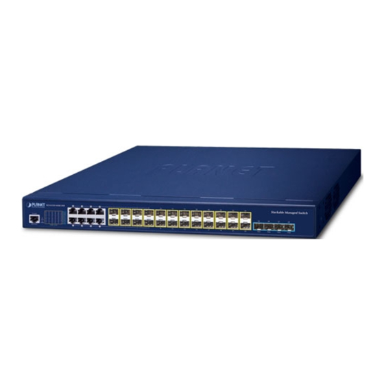
1. Package Contents Thank you for purchasing Layer 3 Gigabit/10 Gigabit Stackable Managed Switch, SGS-6310-16S8C4XR/SGS-6310-24T4X/SGS-6310-24P4X Unless specified, “Managed Switch” mentioned in this Quick Installation Guide refers to the SGS-6310-16S8C4XR/SGS-6310-24T4X/SGS-6310-24P4X. Model Description Layer 3 16-Port 100/1000X SFP + 8-Port Gigabit TP/SFP + SGS-6310-16S8C4XR 4-Port 10G SFP+ Stackable Managed Switch (Dual 100~240V AC) Layer 3 24-Port 10/100/1000T + 4-Port 10G SFP+ SGS-6310-24T4X Stackable Managed Switch Layer 3 24-Port 10/100/1000T 802.3at PoE + 4-Port 10G SGS-6310-24P4X. SFP+ Stackable Managed Switch Open the box of the Managed Switch and carefully unpack it. The box should contain the following items: SGS-6310-16S8C4XR SGS-6310-24T4X SGS-631024P4X... -
Page 4: Switch Management
2. Switch Management To set up the Managed Switch, the user needs to configure the Managed Switch for network management. The Managed Switch provides two management options: Out-of-Band Management and In-Band Management. Out-of-Band Management Out-of-band management is the management through console interface. Generally, the user will use out-of-band management for the initial switch configuration, or when in-band management is not available. -
Page 5: Requirements
3. Requirements z Workstations running Windows XP/2003/Vista/2008/7/8/10, MAC OS X or later, Linux, UNIX, or other platforms are compatible with TCP/IP protocols. z Workstations are installed with Ethernet NIC (Network Interface Card) z Serial Port Connection (Terminal) The above Workstations come with COM Port (DB9) or USB-to-RS232 converter. The above Workstations have been installed with terminal emulator, such as Tera Term or PuTTY. -
Page 6: Terminal Setup
4. Terminal Setup To configure the system, connect a serial cable to a COM port on a PC or notebook computer and to serial (console) port of the Managed Switch. The console port of the Managed Switch is DCE already, so that you can connect the console port directly through PC without the need of Null Modem. -
Page 7: Logging On To The Console
4.1 Logging on to the Console Once the terminal is connected to the device, power on the Managed Switch, and the terminal will display “running testing procedures”. Then, the following message asks for the login user name and password. The factory default user name and password are as follows as the login screen in Figure 4-3 appears. - Page 8 The previous command would apply the following settings for the Managed Switch. IPv4 Address: 192.168.1.254 Subnet Mask: 255.255.255.0 Figure 4-4 Configuring IPv4 Address Screen To check the current IP address or modify a new IP address for the Managed Switch, please use the procedures as follows: Show the current IP address 1. On “Switch#” prompt, enter “show ip interface brief”. 2. The screen displays the current IP address, subnet mask and gateway as shown in Figure 4-5.
-
Page 9: Setting 1000Base-X For 10G Sfp+ Port
4.3 Setting 1000BASE-X for 10G SFP+ Port The Managed Switch supports both 1000BASE-X and 10GBASE-X SFP transceivers by manual setting and the default SFP+ port speed is set in the fiber auto mode, so the end-user can plug the transceiver directly. In another example, the end-user has to force the fiber connection with 1000BASE-X SFP transceiver in the tgigaethernet 0/1. The following command configuration is required: Switch#config... -
Page 10: Starting Web Management
5. Starting Web Management The Managed Switch provides a built-in browser interface. You can manage it remotely by having a remote host with Web browser, such as Microsoft Internet Explorer, Mozilla Firefox, Google Chrome or Apple Safari. Managed Switch RJ45/UTP Cable PC/Workstation with IP Address: Web Browser 192.168.0.254 192.168.0.X Figure 5-1 IP Management Diagram... -
Page 11: Logging In To The Managed Switch From Copper Ports
5.1 Logging in to the Managed Switch from copper ports 1. Use Internet Explorer 8.0 or above Web browser and enter IP address http://192.168.0.254 (that you have just set in console) to access the Web interface. 2. When the following dialog box appears, please enter the configured username “admin” and password “admin” (or the username/password you have changed via console). The login screen in Figure 5-2 appears. -
Page 12: Saving Configuration Via The Web
4. The Switch Menu on the left of the Web page lets you access all the commands and statistics the Switch provides. Now, you can use the Web management interface to continue the Switch management or manage the Managed Switch by console interface. Please refer to the user manual for more. -
Page 13: Led Indicators
6. LED Indicators 6.1 SGS-6310-24T4X System Color Function Green Lights to indicate that the Switch has power. Power is off. Green Slow blinks to indicate the system is normally starting up. Interfaces Color Function Indicating the port is running and the connection is Lights successfully established. LNK/ACT Green Indicating that the switch is actively sending or Blinks receiving data over that port. 10G Status LED Color Function Indicating the port is running and the connection is Lights successfully established. LNK/ACT Green (Ports 25-28) Indicating that the switch is actively sending or... -
Page 14: Sgs-6310-24P4X
6.2 SGS-6310-24P4X System Color Function Green Lights to indicate that the Switch has power. Power is off. Green Slow blinks to indicate the system is normally starting up. Interfaces Color Function Indicating the port is running at 1000Mbps speed Lights and successfully established. 1000 LNK/ Green Indicating that the switch is actively sending or Blinks receiving data over that port. Indicating the port is running at 10/100Mbps Lights speed and successfully established. 10/100 LNK/ Amber Indicating that the switch is actively sending or Blinks receiving data over that port. 10G Status LED Color Function Indicating the port is running at 10Gbps speed Lights and successfully established. 10G LNK/ Amber Indicating that the switch is actively sending or Blinks receiving data over that port. -
Page 15: Sgs-6310-16S8C4Xr
6.3 SGS-6310-16S8C4XR System Color Function Green Lights to indicate that the Switch has power. Power is off. Green Slow blinks to indicate the system is normally starting up. Interfaces Color Function Indicating the port is running and the connection is Lights successfully established. LNK/ACT Green Indicating that the switch is actively sending or Blinks receiving data over that port. 10G Status LED Color Function Indicating the port is running and the connection is Lights successfully established. LNK/ACT Green (Ports 25-28) Indicating that the switch is actively sending or Blinks receiving data over that port. -
Page 16: Customer Support
7. Customer Support Thank you for purchasing PLANET products. You can browse our online FAQ resource at the PLANET Web site first to check if it could solve your issue. If you need more support information, please contact PLANET support team. PLANET online FAQs: http://www.planet.com.tw/en/support/faq.php?type=1 Support team mail address: support@planet.com.tw SGS-6310-Series User’s Manual https://www.planet.com.tw/en/support/downloads?&method=keyword&keyword=S GS-6310&view=3#list Copyright ©...
Need help?
Do you have a question about the SGS-6310 Series and is the answer not in the manual?
Questions and answers