Table of Contents
Advertisement
Quick Links
Advertisement
Table of Contents

Subscribe to Our Youtube Channel
Related Manuals for Planet Networking & Communication FGSW-1816HPS


Summary of Contents for Planet Networking & Communication FGSW-1816HPS
- Page 1 User’s Manual of FGSW-1816HPS...
- Page 2 User’s Manual of FGSW-1816HPS Trademarks Copyright © PLANET Technology Corp. 2014. Contents are subject to revision without prior notice. PLANET is a registered trademark of PLANET Technology Corp. All other trademarks belong to their respective owners. Disclaimer PLANET Technology does not warrant that the hardware will work properly in all environments and applications, and makes no warranty and representation, either implied or expressed, with respect to the quality, performance, merchantability, or fitness for a particular purpose.
-
Page 3: Table Of Contents
User’s Manual of FGSW-1816HPS TABLE OF CONTENTS 1. INTRODUCTION........................6 1.1 Packet Contents ............................6 1.2 Product Description .............................7 1.3 How to Use This Manual ..........................10 1.4 Product Features............................11 1.5 Product Specifications ..........................13 2. INSTALLATION ........................15 2.1 Hardware Description ..........................15 2.1.1 Switch Front Panel ..............................15... - Page 4 User’s Manual of FGSW-1816HPS 4.2.7 NTP Setting .................................35 4.3 Port Management ............................37 4.3.1 Port Configuration..............................38 4.3.2 Port Mirroring...............................40 4.3.3 Bandwidth Control ...............................41 4.3.4 Broadcast Storm Control............................43 4.3.5 Port Statistics...............................44 4.4 VLAN................................46 4.4.1 VLAN Overview ..............................46 4.4.2 VLAN Basic Information............................48 4.4.2.1 Port-based VLAN mode..........................48 4.4.2.2 Tag-based VLAN Mode ..........................48...
- Page 5 User’s Manual of FGSW-1816HPS 4.10.2 PoE Status.................................80 4.10.3 PoE Port Setting ..............................81 4.10.4 Port Sequential ..............................84 4.10.5 PoE Schedule..............................85 4.11 Configuration Backup / Upload.......................88 4.12 Misc Operation ............................89 4.13 SNMP .................................94 4.14 Logout ...............................96 5. SWITCH OPERATION ......................97 5.1 Address Table .............................97 5.2 Learning ..............................97...
-
Page 6: Introduction
1. INTRODUCTION Thanks you for purchasing 16-Port 10/100Base-TX 802.3at PoE + 2-Port Gigabit TP/SFP Combo Web Smart Ethernet Switch, FGSW-1816HPS. “PoE Web Smart Switch” mentioned in this Guide refers to the FGSW-1816HPS. 1.1 Packet Contents Open the box of the PoE Web Smart Switch and carefully unpack it. The box should contain the following items: ... -
Page 7: Product Description
7.2Gbps high-performance switch architecture and 220-watt PoE power budget, the recorded video files from 16 PoE IP cameras can be powered by the FGSW-1816HPS and saved in the 8 / 16 / 32-channel NVR systems or surveillance software to perform comprehensive security monitoring. For instance, one FGSW-1816HPS can be combined with one 16-channel NVR and 16 PoE IP cameras as a kit for the administrators to centrally and efficiently manage the surveillance system in the local LAN and the remote site via Internet. - Page 8 Intelligent LED Indicator for Real-time PoE Usage The FGSW-1816HPS helps users to monitor the current status of PoE power usage easily and efficiently by its advanced LED indication. Called “PoE Power Usage”, the front panel of the FGSW-1816HPS Fast Ethernet PoE+ Switch has four orange LEDs indicating 50W, 100W, 150W and 190W of PoE power usage.
- Page 9 User’s Manual of FGSW-1816HPS Flexible and Extendable Uplink Solution The FGSW-1816HPS provides 2 extra Gigabit TP/SFP combo interfaces supporting 10/100/1000Base-T RJ-45 copper to connect with surveillance network devices such as NVR, Video Streaming Server or NAS to facilitate surveillance management. Or through these dual-speed fiber SFP slots, it can also connect with the 1000Base-SX/LX SFP (Small Form-factor Pluggable) fiber transceiver to uplink to backbone switch and monitoring center in long distance.
-
Page 10: How To Use This Manual
User’s Manual of FGSW-1816HPS 1.3 How to Use This Manual This User Manual is structured as follows: Section 2, INSTALLATION The section explains the functions of the Switch and how to physically install the PoE Web Smart Switch. Section 3, SWITCH MANAGEMENT The section contains the information about the software function of the PoE Web Smart Switch. -
Page 11: Product Features
User’s Manual of FGSW-1816HPS 1.4 Product Features Physical Port 16-port 10/100Base-TX RJ45 copper with PoE in-line supported 2-port 10/100/1000Base-T RJ45 copper 2 1000Base-X mini-GBIC/SFP slots to share with Port-17 to Port-18 Reset button for system management ... - Page 12 User’s Manual of FGSW-1816HPS TCP / UDP port-based QoS Strict priority and Weighted Round Robin (WRR) CoS policies Multicast Supports IGMP Snooping v1 and v2 Security Physical port to MAC address binding TCP/UDP port number filter: Forwarding or discarding typical network applications ...
-
Page 13: Product Specifications
User’s Manual of FGSW-1816HPS 1.5 Product Specifications Product FGSW-1816HPS Hardware Specifications 16 10/100Base-TX RJ45 Auto-MDI/MDI-X ports 10/100Mbps Copper Ports 2 10/100/1000Base-T RJ45 Auto-MDI/MDI-X ports Gigabit Copper Ports 2 1000Base-X SFP interfaces, shared with Port-17 to Port-18 SFP/mini-GBIC Slots Store-and-Forward Switch Architecture 7.2Gbps / non-blocking... - Page 14 User’s Manual of FGSW-1816HPS 7 units PD @ 30.8 watts Layer 2 Functions Port disable / enable Auto-negotiation 10/100/1000Mbps full and half duplex mode selection Port Configuration Flow Control disable / enable Display each port’s speed duplex mode, link status, flow control status, auto...
-
Page 15: Installation
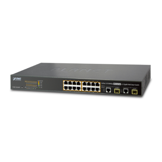
Figure 2-1 shows the front panel of the FGSW-1816HPS. Front Panel Figure 2-1 FGSW-1816HPS front panel ■ Fast Ethernet TP interface 10/100Base-TX Copper, RJ-45 Twist-Pair: Up to 100 meters. ■ Gigabit TP Interface Port-17, Port-18: 10/100/1000Base-T Copper, RJ-45 Twist-Pair: up to 100 meters. -
Page 16: Led Indications
The front panel LEDs indicate instant status of port links, data activity and system power, and help monitor and troubleshoot when needed. Figure 2-2 shows the LED indications of these PoE Web Smart Switches. LED Indication Figure 2-2 FGSW-1816HPS LED panel System Color Function Lights to indicate that the Switch has power. -
Page 17: Switch Rear Panel
PoE Web Smart Switches Rear Panel Figure 2-3 Rear panel of FGSW-1816HPS ■ AC Power Receptacle For compatibility with electric service in most areas of the world, the PoE Web Smart Switch’s power supply automatically adjusts to line power in the range of 100-240V AC and 50/60 Hz. -
Page 18: Installing The Switch
User’s Manual of FGSW-1816HPS 2.2 Installing the Switch This section describes how to install your PoE Web Smart Switch and make connections to the PoE Web Smart Switch. Please read the following topics and perform the procedures in the order being presented. To install your PoE Web Smart Switch on a desktop or shelf, simply complete the following steps. -
Page 19: Rack Mounting
User’s Manual of FGSW-1816HPS 2.2.2 Rack Mounting To install the PoE Web Smart Switch in a 19-inch standard rack, please follow the instructions described below. Place the PoE Web Smart Switch on a hard flat surface, with the front panel positioned towards the front side. -
Page 20: Installing The Sfp Transceiver
User’s Manual of FGSW-1816HPS Proceeds with the steps 4 and 5 of session 2.2.1 Desktop Installation to connect the network cabling and supply power Step6: to the PoE Web Smart Switch. 2.2.3 Installing the SFP transceiver The sections describe how to insert an SFP transceiver into an SFP slot. - Page 21 User’s Manual of FGSW-1816HPS Gigabit Ethernet Transceiver (1000Base-BX, Single Fiber Bi-Directional SFP) Connector Model Speed (Mbps) Fiber Mode Distance Wavelength (TX) Wavelength (RX) Operating Temp. Interface 0 ~ 60 ℃ MGB-LA10 1000 WDM(LC) Single Mode 10km 1310nm 1550nm MGB-LB10 1000...
- Page 22 User’s Manual of FGSW-1816HPS Remove the Transceiver Module Make sure there is no network activity anymore. Remove the Fiber-Optic Cable gently. Lift up the lever of the MGB module and turn it to a horizontal position. Pull out the module gently through the lever.
-
Page 23: Switch Management
User’s Manual of FGSW-1816HPS 3. SWITCH MANAGEMENT This chapter explains the methods that you can use to configure management access to the PoE Web Smart Switch. It describes the types of management applications and the communication and management protocols that deliver data between your management device (workstation or personal computer) and the system. -
Page 24: Management Access Overview
User’s Manual of FGSW-1816HPS 3.2 Management Access Overview The PoE Web Smart Switch gives you the flexibility to access and manage it using any or all of the following methods: Web browser interface An external SNMP-based network management application The Web browser management is embedded in the PoE Web Smart Switch software and available for immediate use. -
Page 25: Snmp-Based Network Management
User’s Manual of FGSW-1816HPS You can then use your Web browser to list and manage the PoE Web Smart Switch configuration parameters from one central location, just as if you were directly connected to the PoE Web Smart Switch's console port. Web Management requires either Microsoft Internet Explorer 8.0 or later, Google Chrome, Safari or Mozilla Firefox 1.5 or later. -
Page 26: Web Configuration
User’s Manual of FGSW-1816HPS 4. WEB CONFIGURATION This section introduces the configuration and functions of the Web-based management. About Web-based Management The PoE Web Smart Switch offers management features that allow users to manage the PoE Web Smart Switch from anywhere on the network through a standard browser such as Microsoft Internet Explorer. - Page 27 User’s Manual of FGSW-1816HPS When the following login screen appears, please enter "admin" as the default username and “admin” as the password (unless you have changed these, in which case use your own login details) to log in the main screen of the PoE Web Smart Switch.
-
Page 28: Main Web Page
User’s Manual of FGSW-1816HPS 4.1 Main Web Page The PoE Web Smart Switch provides a Web-based browser interface for configuring and managing it. This interface allows you to access the PoE Web Smart Switch using the Web browser of your choice. This chapter describes how to use the PoE Web Smart Switch’s Web browser interface to configure and manage it. - Page 29 User’s Manual of FGSW-1816HPS Figure 4-1-2 PoE Web Smart Switch Main Functions Menu...
-
Page 30: System
User’s Manual of FGSW-1816HPS 4.2 System Use the System menu items to display and configure basic administrative details of the PoE Web Smart Switch. Under the System, the following topics are provided to configure and view the system information: This section has the following items: The switch system information is provided here. -
Page 31: Ip Configurations
User’s Manual of FGSW-1816HPS Hardware Version The version of hardware. Software Version The version of software Idle Time Security Set idle time and behavior. Buttons : Click to apply changes 4.2.2 IP Configurations The IP configuration includes the IP Address, Subnet Mask and Gateway. The configured column is used to view or change the IP configuration. -
Page 32: Password Setting
User’s Manual of FGSW-1816HPS 4.2.3 Password Setting This page provides a configuration of the current User name and Password. After the setup is completed, please press “Apply” button to take effect. Please log in web interface with new user name and password and the screens in Figure 4-2-3 appear. -
Page 33: Firmware Update
User’s Manual of FGSW-1816HPS Press “Factory Default” button to take affect. After finish the operation, the following screen in Figure 4-2-5 appears and please press “Reboot” button and it will back to the Web login screen. After input default username and password then can continue the PoE Web Smart Ethernet Switch management. - Page 34 User’s Manual of FGSW-1816HPS Key in the password and press “Update” button to take effect, after press the “Update” button, the screen in Figure 4-2-7 appears. The warning message for double confirming. Figure 4-2-7 Warning Message Screen Press “OK” button for start the firmware upgrade process, the screen in Figure 4-2-8 appears.
-
Page 35: Reboot
User’s Manual of FGSW-1816HPS When firmware upgrade process is completed then the following screen appears, please press the “continue” button and wait for system reboot. After device reboot then can use the latest firmware of the PoE Web Smart Ethernet Switch. - Page 36 User’s Manual of FGSW-1816HPS Figure 4-2-13 SNTP Setup Page Screenshot The page includes the following fields: Object Description System Time Display current system time NTP Server Configure IP address of NTP Server Time Zone Allow to select the time zone according to current location of switch.
-
Page 37: Port Management
User’s Manual of FGSW-1816HPS 4.3 Port Management Use the Port Menu to display or configure the PoE Web Smart Switch's ports. This section has the following items: Configure port configuration settings 。 Port Configuration Set the source and target ports for mirroring 。... -
Page 38: Port Configuration
User’s Manual of FGSW-1816HPS 4.3.1 Port Configuration This page displays current port configurations and status. Ports can also be configured here. The table has one row for each port on the selected switch in a number of columns, which are:... - Page 39 User’s Manual of FGSW-1816HPS Auto-Negotiation Enable and Disable. Being set as Auto, the speed and duplex mode are negotiated automatically. When you set it as Disable, you have to set the speed and duplex mode manually Enable – Start up the Auto negotiation.
-
Page 40: Port Mirroring
User’s Manual of FGSW-1816HPS 4.3.2 Port Mirroring Configure port Mirroring on this page. This function provides the monitoring of network traffic that forwards a copy of each incoming or outgoing packet from one port of a network Switch to another port where the packet can be studied. It enables the manager to keep close track of switch performance and alter it if necessary. -
Page 41: Bandwidth Control
User’s Manual of FGSW-1816HPS Figure 4-3-3 Port Mirroring Settings Page Screenshot The page includes the following fields: Object Description Destination Port Select the port to mirror destination port. Monitored Packets Enable or disable the port mirroring function. Source Port Frames transmitted / received from these ports are mirrored to the mirroring port. - Page 42 User’s Manual of FGSW-1816HPS The page includes the following fields: Object Description Port No Select port number for this drop-down list to enable the function. Tx Rate Configure the Tx rate for the selected port. Valid values are in the range from 0 to 255; 0 is unlimited rate.
-
Page 43: Broadcast Storm Control
User’s Manual of FGSW-1816HPS Rx Rate Display the current Rx rate limitation. Link Speed Display the current link speed information. 4.3.4 Broadcast Storm Control This section introduces detail settings of Broadcast Storm Control function of PoE Web Smart Ethernet Switch. -
Page 44: Port Statistics
User’s Manual of FGSW-1816HPS 4.3.5 Port Statistics This page provides an overview of traffic statistics for all switch ports. The Port Statistics screens in Figure 4-3-7 appears. Figure 4-3-7 Port Statistics Web Page Screenshot The page includes the following fields:... - Page 45 User’s Manual of FGSW-1816HPS resources. CRC error packet & Receive Packet The number of CRC/alignment errors (FCS or alignment errors). Buttons : Click to clear statistics. : Click to refresh the page.
-
Page 46: Vlan
User’s Manual of FGSW-1816HPS 4.4 VLAN 4.4.1 VLAN Overview A Virtual Local Area Network (VLAN) is a network topology configured according to a logical scheme rather than the physical layout. VLAN can be used to combine any collection of LAN segments into an autonomous user group that appears as a single LAN. - Page 47 User’s Manual of FGSW-1816HPS IEEE 802.1Q Tag-based VLAN IEEE 802.1Q (tagged) VLAN is implemented on the Switch. 802.1Q VLAN requires tagging, which enables them to span the entire network (assuming all switches on the network are IEEE 802.1Q-compliant). VLAN allow a network to be segmented in order to reduce the size of broadcast domains. All packets entering a VLAN will only be forwarded to the stations (over IEEE 802.1Q enabled switches) that are members of that VLAN, and this includes...
-
Page 48: Vlan Basic Information
User’s Manual of FGSW-1816HPS 4.4.2 VLAN Basic Information The VLAN Basic Information page displays basic information on the VLAN type supported by the PoE Web Smart Switch. The VLAN Basic Information screen in Figure 4-4-1 appears. Figure 4-4-1: VLAN Basic Information Page Screenshot... - Page 49 User’s Manual of FGSW-1816HPS Figure 4-4-3 Change VLAN Mode Warning Web Page Screen Press “Continue” button, the current Port-based VLAN mode will swap to the Tag-based VLAN mode. The Screen in Figure 4-4-4 will appear. Figure 4-4-4 802.1Q VLAN Configuration Web Page Screen...
-
Page 50: Vlan Port Configuration
User’s Manual of FGSW-1816HPS Buttons : Click to apply changes : Click to change VLAN mode. 4.4.3 VLAN Port Configuration This page introduces detailed information of VLAN Member function of switch. It has two of VLAN Member types, one is for Port-based VLAN mode and one is for Tag-based VLAN mode. -
Page 51: Tag-Based Vlan Mode
User’s Manual of FGSW-1816HPS 4.4.3.2 Tag-based VLAN Mode The VLAN Port Configuration screen in Figure 4-4-6 appears. Figure 4-4-6: Tag-based VLAN Port Configuration Page Screenshot The page includes the following fields: Object Description Allow to assign PVID(Port VLAN ID) for selected port. -
Page 52: Multi To 1 Setting
User’s Manual of FGSW-1816HPS 4.4.4 Multi to 1 Setting This setting is exclusive to VLAN setting on ”VLAN member setting “. When VLAN member setting is updated, multi-to-1 setting will be void and vice versa. The “disabled port” means the port is excluded in this setting. The function is for Port-based VLAN only. -
Page 53: Quality Of Service
User’s Manual of FGSW-1816HPS 4.5 Quality of Service 4.5.1 QoS overview Quality of Service (QoS) is an advanced traffic prioritization feature that allows you to establish control over network traffic. QoS enables you to assign various grades of network service to different types of traffic, such as multi-media, video, protocol-specific, time critical, and file-backup traffic. -
Page 54: Class Of Service Configuration
User’s Manual of FGSW-1816HPS Figure 4-5-1 Priority Model Setting Page Screenshot The page includes the following fields: Object Description Configure QoS mode. The options: Mode First-In-First-Out All-High-before-Low Weighted-Round-Robin 4.5.3 Class of Service Configuration The Class of Service Configuration and Information screen in Figure 4-5-2 appears. -
Page 55: Tcp/Udp Port Based Qos
User’s Manual of FGSW-1816HPS 4.5.4 TCP/UDP Port Based QoS The TCP/UDP Port-based QoS and Information screen in Figure 4-5-3 appears. Figure 4-5-3 TCP/UDP Port Base QoS Setting Page Screenshot... - Page 56 User’s Manual of FGSW-1816HPS The page includes the following fields: Object Description Protocol Select IP port number value for the list. Option Select QoS option for this drop-down list. Options: F-I-F-O - The output queue assignment is determined with first-come, first-served (FCFS) behaviour ...
-
Page 57: Security
User’s Manual of FGSW-1816HPS 4.6 Security This section is to control the access to the PoE Web Smart Switch, including the MAC Address Filter and TCP/UDP Filter. The Security Page contains links to the following main topics: MAC Address Filter ... -
Page 58: Tcp/Udp Filter
User’s Manual of FGSW-1816HPS Enable Disable MAC address Configure binding MAC address for this table Buttons : Click to apply changes : Click to read the information. 4.6.2 TCP/UDP Filter The TCP/UDP Filter and Information screen in Figure 4-6-2 appears. - Page 59 User’s Manual of FGSW-1816HPS forwarded. Secure WAN port Select Port for this drop-down list. The egress traffic will be checked whether Port Filter Rule is to drop or to forward packets Buttons : Click to apply changes...
-
Page 60: Spanning Tree
User’s Manual of FGSW-1816HPS 4.7 Spanning Tree 1. Theory The Spanning Tree Protocol can be used to detect and disable network loops, and to provide backup links between switches, bridges or routers. This allows the switch to interact with other bridging devices in your network to ensure that only one route exists between any two stations on the network, and provide backup links which automatically take over when a primary link goes down. - Page 61 User’s Manual of FGSW-1816HPS The switch sends BPDUs to communicate and construct the spanning-tree topology. All switches connected to the LAN on which the packet is transmitted will receive the BPDU. BPDUs are not directly forwarded by the switch, but the receiving switch uses the information in the frame to calculate a BPDU, and, if the topology changes, initiates a BPDU transmission.
- Page 62 User’s Manual of FGSW-1816HPS Figure 4-7-1 STP Port Status Transitions You can modify each port status by using management software. When you enable STP, every port on every switch in the network goes through the blocking status and then transitions through the statuses of listening and learning at power up. If properly configured, each port stabilizes to the forwarding or blocking statis.
- Page 63 User’s Manual of FGSW-1816HPS a 16-bit priority and a 48-bit Ethernet MAC below) address 32768 + MAC A relative priority for each switch – lower 32768 Priority numbers give a higher priority and a greater chance of a given switch being elected as...
- Page 64 User’s Manual of FGSW-1816HPS Hello Time – The Hello Time can be from 1 to 10 seconds. This is the interval between two transmissions of BPDU packets sent by the Root Bridge to tell all other Switches that it is indeed the Root Bridge. If you set a Hello Time for your Switch, and it is not the Root Bridge, the set Hello Time will be used if and when your Switch becomes the Root Bridge.
- Page 65 User’s Manual of FGSW-1816HPS Figure 4-7-2 Before Applying the STA Rules In this example, only the default STP values are used. Figure 4-7-3 After Applying the STA Rules...
-
Page 66: Stp Bridge Settings
User’s Manual of FGSW-1816HPS The switch with the lowest Bridge ID (switch C) was elected the root bridge, and the ports were selected to give a high port cost between switches B and C. The two (optional) Gigabit ports (default port cost = 20,000) on switch A are connected to one (optional) Gigabit port on both switch B and C. - Page 67 User’s Manual of FGSW-1816HPS current status. Valid values are in the range 6 to 40 seconds. -Default: -Minimum: The higher of 1 -Maximum: The lower of 10 Max Age (6~40 Sec) The maximum age of the information transmitted by the Bridge when it is the Root Bridge.
-
Page 68: Stp Port Settings
User’s Manual of FGSW-1816HPS The page includes the following fields: Object Description Root ID Display the Root ID Hello Time Display the Hello Time Max Age Display the Max Age Forward Delay Display the Forward Delay... - Page 69 User’s Manual of FGSW-1816HPS The STP Port Status screen in Figure 4-7-8 appears. Figure 4-7-8 STP Port Status Page Screenshot The page includes the following fields: Object Description Path Cost Display the STP Mode Status Priority Display the Port Priority ...
-
Page 70: Loopback Detection
User’s Manual of FGSW-1816HPS 4.7.3 Loopback Detection The Loopback Detection function avoids that user loops network. The Loopback Detection screens in Figure 4-7-9 appears. Figure 4-7-9 Loopback Detection Setting Page Screenshot The page includes the following fields: Object Description Loopback Detection Select Loopback Detection mode for this drop down list. - Page 71 User’s Manual of FGSW-1816HPS Figure 4-7-10 Loopback Detection Status Page Screenshot The page includes the following fields: Object Description Status Display the Status of Loopback Detection Buttons : Click to apply changes : Click to reset the status...
-
Page 72: Trunking Setting
User’s Manual of FGSW-1816HPS 4.8 Trunking Setting Port Aggregation optimizes port usage by linking a group of ports together to form a single Link Aggregated Groups (LAGs). Port Aggregation multiplies the bandwidth between the devices, increases port flexibility, and provides link redundancy. - Page 73 User’s Manual of FGSW-1816HPS The Link Aggregation Control Protocol (LACP) provides a standardized means for exchanging information between Partner Systems that require high speed redundant links. Link aggregation lets you group up to eight consecutive ports into a single dedicated connection. This feature can expand bandwidth to a device on the network. LACP operation requires full-duplex mode, more detail information refer to the IEEE 802.3ad standard.
-
Page 74: Link Aggregation Settings
User’s Manual of FGSW-1816HPS 4.8.1 Link Aggregation Settings This page allows configuring Link Aggregation Settings. The Link Aggregation Settings screens in Figure 4-8-2 appears. Figure 4-8-2 LAG Setting Page Screenshot The page includes the following fields: Object Description The Priority controls the priority of the port. - Page 75 User’s Manual of FGSW-1816HPS Static: Force aggregared selected ports to be a trunk group. LACP: LACP LAG negotiate Aggregated Port links with other LACP ports located on a different device. If the other device ports are also LACP ports, the devices establish a LAG between them.
-
Page 76: Dhcp Relay Agent
User’s Manual of FGSW-1816HPS 4.9 DHCP Relay Agent Configure DHCP Relay on this Page. DHCP Relay is used to forward and to transfer DHCP messages between the clients and the server when they are not on the same subnet domain. -
Page 77: Dhcp Relay Server
User’s Manual of FGSW-1816HPS Count Limit (1-16) DHCP Relay Option 82 Indicates the DHCP relay information mode option operation. Possible modes are: Status Enabled: Enable DHCP relay information mode operation. When enabling DHCP relay information mode operation, the agent inserts specific information (option82) into a DHCP message when forwarding to DHCP server and removing it from a DHCP message when transferring to DHCP client. -
Page 78: Vlan Map Relay Agent
User’s Manual of FGSW-1816HPS Buttons : Click to add changes : Click to delete changes 4.9.3 VLAN MAP Relay Agent This page allows configuring VLAN MAP Relay Agent Settings. The VLAN MAP Relay Agent settings screens in Figure 4-9-4 appears. -
Page 79: Poe Setting
4.10 PoE Setting Providing up to 16 PoE, in-line power interfaces, the FGSW-1816HPS PoE Switch can easily build a power central-controlled IP phone system, IP Camera system, AP group for the enterprise. For instance, 16 camera / AP can be easily installed around the corner in the company for surveillance demands or build a wireless roaming environment in the office. -
Page 80: Poe Status
User’s Manual of FGSW-1816HPS PoE Splitter PoE Splitter split the PoE 48V DC over the Ethernet cable into 5/12V DC power output. It frees the device deployment from restrictions due to power outlet locations, which eliminate the costs for additional AC wiring 3~12 watts and reduces the installation time. -
Page 81: Poe Port Setting
User’s Manual of FGSW-1816HPS Figure 4-10-1 PoE Status Screenshot The page includes the following fields: Object Description Power Supply Budget Configure the total watts usage of PoE Switch. System Operation Display the current System Operation Status. Status Current Power Display the current Current Power Consumption. - Page 82 User’s Manual of FGSW-1816HPS The Page includes the following fields: Object Description Status There are two modes for PoE status. Enable: Enable PoE function. Disable: Disable PoE function. Mode Allows user to select 802.3at or 802.3af compatibility mode. The default vaule is 802.3at mode.
- Page 83 User’s Manual of FGSW-1816HPS Figure 4-10-3 PoE Port Status Page Screenshot The page includes the following fields: Object Description Port This is the logical port number for this row. Status Display Port Status of PoE Port Setting Mode Display per PoE port operate at 802.3af or 802.3at mode.
-
Page 84: Port Sequential
User’s Manual of FGSW-1816HPS 4.10.4 Port Sequential This page allows the user to configure the PoE Ports started up interval time. PoE delay is to delay power feeding when the switch is completely booted up Figure 4-10-4 shows. Figure 4-10-4: PoE Port Sequential Configuration Screenshot The PoE port will start providing power after the whole system program has finished running. -
Page 85: Poe Schedule
User’s Manual of FGSW-1816HPS Figure 4-10-5 PoE Port Sequential Setting Status Page Screenshot The page includes the following fields: Object Description Port This is the logical port number for this row. Delay Mode Display delay mode of Port Sequential ... - Page 86 User’s Manual of FGSW-1816HPS The screen in Figure 4-10-6 appears. Figure 4-10-6: PoE Schedule Screenshot...
- Page 87 User’s Manual of FGSW-1816HPS Before enabling PoE Schedule function, please configure NTP settings well to make sure the time is current time. The page includes the following fields: Object Description Schedule on Port Set the schedule mode for slected port.
-
Page 88: Configuration Backup / Upload
User’s Manual of FGSW-1816HPS 4.11 Configuration Backup / Upload This page provides Backup/Recovery of PoE Web Smart Ethernet Switch; the screen in Figure 4-11-1 appears. Figure 4-11-1: PoE Schedule Screenshot The page includes the following fields: Object Description Backup (Switch PC) Allow to backup current configuration to PC. -
Page 89: Misc Operation
User’s Manual of FGSW-1816HPS 4.12 Misc Operation The Internet Group Management Protocol (IGMP) lets host and routers share information about multicast groups memberships. IGMP snooping is a switch feature that monitors the exchange of IGMP messages and copies them to the CPU for feature processing. - Page 90 User’s Manual of FGSW-1816HPS Figure 4-12-2 Multicast Flooding Figure 4-12-3 IGMP Snooping Multicast Stream Control...
- Page 91 User’s Manual of FGSW-1816HPS IGMP Versions 1 and 2 Multicast groups allow members to join or leave at any time. IGMP provides the method for members and multicast routers to communicate when joining or leaving a multicast group. IGMP version 1 is defined in RFC 1112. It has a fixed packet size and no optional data.
- Page 92 User’s Manual of FGSW-1816HPS The states a computer will go through to join or to leave a multicast group are shown below: Figure 4-12-4 IGMP State Transitions Configure Miscellaneous functions on this Page. This section has the following items: Configure Output Queue Aging Time settings 。...
- Page 93 User’s Manual of FGSW-1816HPS The Page includes the following fields: Object Description Aging time(ms) Use higher Output Queue Aging Time will have bad utilization of shared buffer and performance. Possible modes are: Disabled: Disable Output Queue Aging Time operation ...
-
Page 94: Snmp
User’s Manual of FGSW-1816HPS 4.13 SNMP The Simple Network Management Protocol (SNMP) is an application layer protocol that facilitates the exchange of management information between network devices. It is part of the Transmission Control Protocol/Internet Protocol (TCP/IP) protocol suite. SNMP enables network administrators to manage network performance, find and solve network problems, and plan for network growth. - Page 95 User’s Manual of FGSW-1816HPS Figure 4-13-1 SNMP Configuration Page Screenshot The Page includes the following fields: Object Description Community Name A string identifying the SNMP Community name that this entry should belong to. Access Right Indicates the SNMP community type operation. Possible types are: RO=Read Only: Set access string type in read-only mode.
-
Page 96: Logout
User’s Manual of FGSW-1816HPS Disabled: Disable SNMP Trap Server operation Trap Server Address Configure the SNMP Trap Server IP address Trap Server Status Display the SNMP Trap Server status Buttons : Click to apply changes 4.14 Logout This page allows enabling Logout Settings. The Logout settings screens in Figure 4-14-1 appears. -
Page 97: Switch Operation
User’s Manual of FGSW-1816HPS 5. SWITCH OPERATION 5.1 Address Table The Switch is implemented with an address table. This address table composed of many entries. Each entry is used to store the address information of some node in network, including MAC address, port no, etc. This in-formation comes from the learning process of Ethernet Switch. -
Page 98: Auto-Negotiation
User’s Manual of FGSW-1816HPS 5.5 Auto-Negotiation The STP ports on the Switch have built-in "Auto-negotiation". This technology automatically sets the best possible bandwidth when a connection is established with another network device (usually at Power On or Reset). This is done by detect the modes and speeds at the second of both device is connected and capable of, both 10Base-T and 100Base-TX devices can connect with the port in either Half- or Full-Duplex mode. -
Page 99: Power Over Ethernet Overview
User’s Manual of FGSW-1816HPS 6. Power over Ethernet Overview What is PoE? The PoE is an abbreviation of Power over Ethernet; the PoE technology means a system to pass electrical power safely, along with data on Ethernet UTP cable. The IEEE standard for PoE technology requires Category 5 cable or higher for high power PoE levels, but can operate with category 3 cable for low power levels. - Page 100 User’s Manual of FGSW-1816HPS Figure 6-1: Power Supplied over the Spare Pins The data pairs are used. Since Ethernet pairs are transformer coupled at each end, it is possible to apply DC power to the center tap of the isolation transformer without upsetting the data transfer. In this mode of operation the pair on pins 3 and 6 and the pair on pins 1 and 2 can be of either polarity.
-
Page 101: Troubleshooting
User’s Manual of FGSW-1816HPS 7. TROUBLESHOOTING This chapter contains information to help you solve your issue. If the PoE Web Smart Switch is not functioning properly, make sure the PoE Web Smart Switch is set up according to instructions in this manual. - Page 102 User’s Manual of FGSW-1816HPS If that device works, refer to the next step. If that device does not work, check the AC power...
-
Page 103: Switch's Rj-45 Pin Assignments
User’s Manual of FGSW-1816HPS APPENDIX A A.1 Switch's RJ-45 Pin Assignments 1000Mbps, 1000Base T Contact MDI-X BI_DA+ BI_DB+ BI_DA- BI_DB- BI_DB+ BI_DA+ BI_DC+ BI_DD+ BI_DC- BI_DD- BI_DB- BI_DA- BI_DD+ BI_DC+ BI_DD- BI_DC- Implicit implementation of the crossover function within a twisted-pair cable, or at a wiring panel, while not expressly forbidden, is beyond the scope of this standard. - Page 104 User’s Manual of FGSW-1816HPS The standard cable, RJ-45 pin assignment The standard RJ-45 receptacle/connector There are 8 wires on a standard UTP/STP cable and each wire is color-coded. The following shows the pin allocation and color of straight cable and crossover cable connection:...
- Page 105 EC Declaration of Conformity For the following equipment: *Type of Product : 16-Port 10/100TX 802.3at PoE + 2-Port Gigabit TP/SFP Combo Web Smart Ethernet Switch FGSW-1816HPS *Model Number * Produced by: Manufacturer‘s Name : Planet Technology Corp. Manufacturer‘s Address : 10F., No.96, Minquan Rd., Xindian Dist., New Taipei City 231, Taiwan (R.O.C.).
Need help?
Do you have a question about the FGSW-1816HPS and is the answer not in the manual?
Questions and answers