
Related Manuals for Planet Networking & Communication IGS-10020MT


Summary of Contents for Planet Networking & Communication IGS-10020MT
- Page 1 Industrial L2+ Multi-Port Full Gigabit Managed Ethernet Switches IGS-10020MT/IGS-10080MFT IGS-12040MT/IGS-20040MT Quick Installation Guide...
-
Page 2: Table Of Contents
Table of Contents 1. Package Contents ..............3 2. Requirements ................4 3. Wiring the Power Inputs ............5 4. Terminal Setup ................8 4.1 Logging on to the Console ........... 9 4.2 Configuring IP Address ............10 5. Starting Web Management ............12 5.1 Logging in to the Industrial L2+ Managed Switch ....12 5.2. Saving Configuration ............17 6. Recovering Back to Default Configuration ........18... -
Page 3: Package Contents
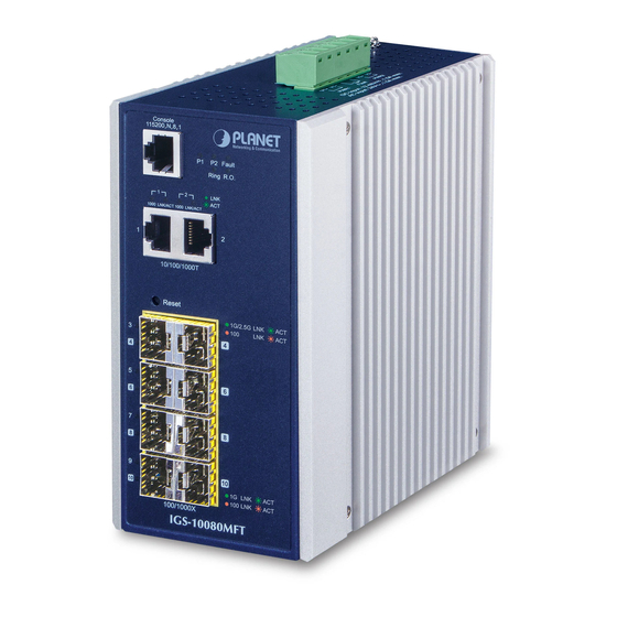
1. Package Contents Thank you for purchasing PLANET Industrial L2+ Multi-Port Gigabit Managed Ethernet Switches, such as IGS-10020MT, IGS-10080MFT, IGS-12040MT and IGS-20040MT. The descriptions of these models are as follows: Industrial 8-Port 10/100/1000T + IGS-10020MT 2-Port 100/1000X SFP Managed Switch Industrial 8-Port 100/1000X SFP + IGS-10080MFT 2-Port 10/100/1000T Managed Switch Industrial 8-Port 10/100/1000T + IGS-12040MT 4-Port 100/1000X SFP Managed Switch Industrial 16-Port 10/100/1000T +... -
Page 4: Requirements
2. Requirements Workstations running Windows XP/2003/Vista/7/8/10/2008, MAC OS X or later, Linux, UNIX, or other platforms are compatible with TCP/ IP protocols Serial Port Connection (Terminal) The above Workstations come with COM Port (DB9) or USB-to- RS232 converter. The above Workstations have been installed with terminal emulator, such as Hyper Terminal included in Windows XP/2003, putty or tera term. -
Page 5: Wiring The Power Inputs
1. Insert positive/negative DC power wires into Contacts 1 and 2 for Power 1, or Contacts 5 and 6 for Power 2. IGS-10020MT: 12~48V DC, 24V AC V1- V1+ V2- V2+ Input DC 12V~48V, AC 24V PWR1 Fault PWR2 Figure 3-1: IGS-10020MT Upper Panel IGS-10080MFT: 12~48V DC, 24V AC V2- V2+ V1- V1+ 1A@24V PWR2 Fault PWR1 Input DC 12V~48V Figure 3-2: IGS-10080MFT Upper Panel... - Page 6 IGS-12040MT: 12~72V DC, 24V AC DO 1 DI 0 DI 1 DO 0 Figure 3-3: IGS-12040MT Upper Panel IGS-20040MT: 9~48V DC, 24V AC Figure 3-4: IGS-20040MT Upper Panel...
- Page 7 2. Tighten the wire-clamp screws for preventing the wires from loos- ening. Power 1 Power 2 Positive (+) Pin Negative (-) Pin IGS-10020MT Pin 2 / 6 Pin 1 / 5 IGS-10080MFT Pin 2 / 6 Pin 1 / 5 IGS-12040MT Pin 1 / 5 Pin 2 / 6 IGS-20040MT Pin 1 / 5 Pin 2 / 6 The wire gauge for the terminal block should be in the range from 12 to 24 AWG.
-
Page 8: Terminal Setup
4. Terminal Setup To configure the system, connect a serial cable to a COM port on a PC or notebook computer and to RJ45 type serial (console) port of the Industrial L2+ Managed Switch. The console port of the Industrial L2+ Managed Switch is DCE already, so that you can connect the console port directly through PC without the need of null modem. -
Page 9: Logging On To The Console
4.1 Logging on to the Console Once the terminal has been connected to the device, power on the Industrial L2+ Managed Switch and the terminal will display “running testing procedures”. 1. There are three switches (IGS-10080MFT/IGS-12040MT/ IGS-20040MT) with the RJ45 type console interface. 2. The following console screen is based on the IGS- 10020HPT; the display of the IGS-10020HPT is the Note same as that of the IGS-10080MFT/IGS-12040MT/... -
Page 10: Configuring Ip Address
4.2 Configuring IP Address The Industrial L2+ Managed Switch is shipped with default IP address shown below: IP Address: 192.168.0.100 Subnet Mask: 255.255.255.0 To check the current IP address or modify a new IP address for the Industrial L2+ Managed Switch, please use the procedure as follows: Display of the current IP Address 1. At the “#” prompt, enter “show ip interface brief”. 2. The screen displays the current IP address shown in Figure 4-4. Figure 4-4: IP Information Screen Configuration of the IP Address 3. At the “#” prompt, enter the following command and press <Enter>... - Page 11 4. Repeat step 1 to check if the IP address has changed. Store the current switch configuration 5. At the “#” prompt, enter the following command and press <Enter>. # copy running-config startup-config Figure 4-6: Saving Current Configuration Command Screen If the IP is successfully configured, the Industrial L2+ Managed Switch will apply the new IP address setting immediately. You can access the Web interface of the Industrial L2+ Managed Switch through the new IP address.
-
Page 12: Starting Web Management
5. Starting Web Management The following shows how to start up the Web Management of the Industrial L2+ Managed Switch. Note the Industrial L2+ Managed Switch is configured through an Ethernet connection. Please make sure the manager PC must be set to the same IP subnet address. For example, the default IP address of the Industrial L2+ Managed Switch is 192.168.0.100, then the manager PC should be set to 192.168.0.x (where x is a number between 1 and 254, except 100),... -
Page 13: Logging In To The Industrial L2+ Managed Switch
“admin” and password “admin” (or the password you have changed before) as shown in Figure 5-2. Default IP Address: 192.168.0.100 Default User Name: admin Default Password: admin Figure 5-2: Web Login Screen The following Web screen is based on the IGS-10020MT; the display of the IGS-10020MT is the same as that of the IGS-10080MFT/IGS-12040MT/IGS-20040MT. Note... - Page 14 3. After entering the password, the main screen appears as shown in Figure 5-3. Figure 5-3: Web Main Screen of Industrial L2+ Managed Switch The Switch Menu on the top of the Web page lets you access all the commands and statistics the Industrial L2+ Managed Switch provides. The Switch Menu always contains one or more buttons, such as “System”, “Switching”, “QoS”, “Security”, “Ring”, “ONVIF” and “Maintenance”.
- Page 15 Figure 5-6: Switch Menu – Switching Figure 5-7: Switch Menu -- QoS Figure 5-8: Switch Menu -- Maintenance...
- Page 16 Figure 5-9: Switch Menu -- Security Figure 5-10: Switch Menu – Ring Figure 5-11: Switch Menu – ONVIF If you are not familiar with Switch functions or the related parameter, press “Help icon” anytime on the Web page to get the help description. Note Now, you can use the Web management interface to continue the Switch management or manage the Switch by console interface.
-
Page 17: Saving Configuration
5.2. Saving Configuration To save all applied changes and set the current configuration as a startup configuration on the Web user interface, the startup- configuration file will be loaded automatically across a system reboot. 1. Click the Save icon on the top Switch Menu bar. Figure 5-12: Save Config -- Hot Key 2. -
Page 18: Recovering Back To Default Configuration
Be noted that all the previous setups will be disappeared after the factory default reset is made. P2 FAULT Ring R.O. 1000 LNK/ACT 1000 LNK/ACT Mini- GBIC 100/1000X SFP Reset Button RESET 1000 Figure 6-1: IGS-10020MT Reset Button Reset Button Figure 6-2: IGS-10080MFT Reset Button... - Page 19 1000 LNK 100 LNK Reset Button IGS-12040MT RESET Figure 6-3: IGS-12040MT Reset Button Reset Button RESET FAULT Ring R.O. Console Figure 6-4: IGS-20040MT Reset Button...
-
Page 20: Customer Support
If you need more support information, please contact PLANET switch support team. PLANET online FAQs: http://www.planet.com.tw/en/support/faq Switch support team mail address: support@planet.com.tw IGS-10020MT/IGS-10080MFT/IGS-12040MT/IGS-20040MT User’s Manual: https://www.planet.com.tw/en/support/downloads?&method=keyword& keyword=IGS&view=3#list (Please select your switch model name from the Product Model drop- down menu.) Copyright © PLANET Technology Corp. 2018. Contents are subject to revision without prior notice.
Need help?
Do you have a question about the IGS-10020MT and is the answer not in the manual?
Questions and answers