Table of Contents
Advertisement
Quick Links
REV AUTHORED BY
CHRIS WALSH
04/09/21
REV DRAFTED BY
CHRIS WALSH
04/09/21
PROPRIETARY: This document contains
proprietary data of Hologic, Inc. No
disclosure, reproduction or use of any part
thereof may be made except by written
permission from Hologic.
REV. RELEASE DATE:
05/04/2021
DATE
DATE
TITLE
PANTHER OPERATOR'S MANUAL, V 6.2,
GLOBAL, IVD, ENGLISH
Before using this document, please consult Agile for the latest revision.
DOCUMENT NUMBER
AW-17791-001
SIZE A
SHEET 1 OF 1
Form ENG-0034-T01, Rev. 006
REV
002
Advertisement
Table of Contents

Related Manuals for Hologic Panther System


Summary of Contents for Hologic Panther System
- Page 1 DATE CHRIS WALSH 04/09/21 PROPRIETARY: This document contains TITLE DOCUMENT NUMBER proprietary data of Hologic, Inc. No disclosure, reproduction or use of any part PANTHER OPERATOR'S MANUAL, V 6.2, AW-17791-001 thereof may be made except by written GLOBAL, IVD, ENGLISH permission from Hologic.
- Page 3 For more contact information visit www.hologic.com. HOLOGIC, Aptima, Aptima Combo 2, Panther, TMA and associated logos, are trademarks and/or registered trademarks of Hologic, Inc. and/or its subsidiaries in the United States and/or other countries. All other trademarks that may appear in this manual are the property of their respective owners.
-
Page 4: Revision History
Revision History Revision History Panther System Operator's Manual The following table lists the current revision history for the manual: Part Number Revision Sections Revised Date 903111 2011-03 Use marking and Material 903448 2012-03 Nubmer 903566 Throughout 2012-06 903629 Throughout 2012-12... -
Page 5: Table Of Contents
Typographical Conventions Safety Symbols Terminology Special Terminology Acronyms/Abbreviations Compliance and Safety Compliance Electromagnetic Compatibility Safety Panther System Warnings System Handling Warnings System Environment Warnings System Configuration Warnings Sample Handling Warnings Consumable, Reagent, and Fluid Warnings Consumable Warnings Reagent Warnings Fluid Warnings ®... -
Page 6: Table Of Contents
Target Capture Transcription-Mediated Amplification (TMA) Hybridization Protection Assay (HPA) Dual Kinetic Assay (DKA) Real-Time Assays Internal Controls for Aptima Assays Panther System Overview Introduction Instrument Overview Canopy Panther Upper Bay Components Reagent Bay ® Panther System Operator’s Manual AW-17791-001 Rev. 002 (EN) - Page 7 Liquid Waste Container Solid Waste Container Panther Universal Fluids Drawer NaOCl Bottle Vacuum Pump Printer Panther System Software Overview Introduction Accessing the Panther System Software Desktop Shield Login Screen Navigating the Software Menu Bar ® Panther System Operator’s Manual AW-17791-001 Rev. 002 (EN)
- Page 8 Table of Contents Interactive Items Selection Button Status Panel Status Panel Bars Additional Status Panel Icons Additional Status Panel Items Panther System Software Screens Desktop Shield Screen Messages Screen Comments Screen Pending Screen Tasks Screen Universal Fluid Bay Screen Waste Management Screen...
- Page 9 Prime Criteria Prime Procedure Force Full Prime Load Panther Assay Reagents Master Lot Setup Add a New Master Lot Inactivate a Master Lot Reactivate a Master Lot Reagent Kit Date Extension ® Panther System Operator’s Manual AW-17791-001 Rev. 002 (EN)
- Page 10 Deleting a Test Order Scheduling STAT Test Orders Running Controls/Calibrators as Specimens Dilution Factors Apply Dilution Factors Delete Dilution Factors Unloading Sample Racks Initiating Assay Processing Pausing Sample Pipetting Resume Pipetting Following Pause ® Panther System Operator’s Manual viii AW-17791-001 Rev. 002 (EN)
- Page 11 Monitoring Test Orders Viewing Test Orders Test Order Status Monitoring Loaded Specimen Status Sample Rack Bay Screen Run Status Screen Specimen Status Specimens Panel Monitoring Control/Calibrator Status Assay Reagents Panel Monitoring Results Timing ® Panther System Operator’s Manual AW-17791-001 Rev. 002 (EN)
- Page 12 Selecting Reports Navigating Reports Printing Reports Exporting Reports Reports Activity Log Report Assay Reagent Report Configuration Report Diagnostics Log Report Exceptions by Worklist Report Exceptions Report Levey-Jennings Report Lot Search Report ® Panther System Operator’s Manual AW-17791-001 Rev. 002 (EN)
- Page 13 Laboratory Check and Cleaning Preparing a Clean Workspace Clean with Sodium Hypochlorite Solution Clean with Prepared Bleach Enhancer Solution (if applicable) Checking for Leaks and Spills Mag Wash Clean Clean the Sample Shield ® Panther System Operator’s Manual AW-17791-001 Rev. 002 (EN)
- Page 14 Random Access Loading—Bidirectional LIS Host Query Manual Download Automatic Host Query Batch Loading Samples with Barcodes Samples without Barcodes Database Administration Auto Purge Log Configuration Purge Logs Purge Results Configuration User Interface ® Panther System Operator’s Manual AW-17791-001 Rev. 002 (EN)
- Page 15 Data Export Management Delimiter Character for Export Files Raw Data Export Directory Security Management Cybersecurity and Data Protection Power Save Management Enable Power Save Mode Time to End Power Save Mode ® Panther System Operator’s Manual xiii AW-17791-001 Rev. 002 (EN)
- Page 16 Reflex Testing Configuration Configuring Automatic Reflex Test Order Assignment Configuring Reflex Test Order Assignment During Rack Load Designating Reflex Tests During Sample Rack Loading Assay Custom Cutoff Value Configuration Troubleshooting Hologic Technical Support ® Panther System Operator’s Manual AW-17791-001 Rev. 002 (EN)
- Page 17 Unresponsive System Shutdown Replaceable Parts Vacuum Trap Filter Replacement Universal Fluid Caps Replacement Waste Bottle O-rings Replacement Appendix A. Panther System Operation Checklist Appendix B. Processing Flags Assay Processing Flags Results Processing Flags Appendix C. System Messages Appendix D. Support Contact Information ®...
-
Page 18: List Of Figures
List of Figures Figure 1. Sample Tube Barcode Label Requirements Figure 2. Target Capture Figure 3. Hybridization Protection Assay Figure 4. Panther System Figure 5. Canopy Figure 6. Panther Upper Bay Figure 7. Reagent Bay Figure 8. Sample Bay Module Figure 9. - Page 19 Figure 50. Bottle Status Panel (Example) Figure 51. Disposing of Liquid Waste Container Contents (Example) Figure 52. Maintenance Activities Screen (Example) Figure 53. New/Activate Master Log Screen (Example) Figure 54. Inactivate Master Lot Window (Example) ® Panther System Operator’s Manual xvii AW-17791-001 Rev. 002 (EN)
- Page 20 Figure 78. Sample Curve Report (Example) Figure 79. Results Screen with Filters Panel (Example) Figure 80. USB Storage Removal Window (Example) Figure 81. Report Parameters for Results Report (Example) Figure 82. Panther System Report Navigation Bar ® Panther System Operator’s Manual xviii AW-17791-001 Rev.
- Page 21 Figure 107. Disposing of Liquid Waste Container Contents (Example) Figure 108. Purge Results Window (Example) Figure 109. Assay Reagent Loading Window (Example) Figure 110. Delimiter Character for Export Files Window Figure 111. LIS Messages Window with ASTM 1394 Selected (Example) ® Panther System Operator’s Manual AW-17791-001 Rev. 002 (EN)
- Page 22 Figure 122. Instrument Info Window—Assay Versions View (Example) Figure 123. Send Logs Window (Example) Figure 124. Disposing of Liquid Waste Container Contents (Example) Figure 125. Sample Rack Loading Screen During Barcode Error (Example) ® Panther System Operator’s Manual AW-17791-001 Rev. 002 (EN)
- Page 23 Table 8. Sample Tube Requirements Table 9. Barcode Requirements Table 10. Allowable Barcode Characters Table 11. Panther System Volume Requirements Table 12. Panther System Dead Space Volume Requirements Table 13. System Capacities and Throughput Table 14. Panther System Components Table 15. Canopy Location Descriptions Table 16.
- Page 24 Controls/Calibrators Tab) Table 50. Reflex Testing Configuration Screen Button Descriptions Table 51. Help Window Buttons Table 52. Logoff/Shutdown Screen Buttons Table 53. Tip Replacement Options Table 54. System Prime Resource Consumption ® Panther System Operator’s Manual xxii AW-17791-001 Rev. 002 (EN)
- Page 25 Table 78. Levey-Jennings Report—Report Parameters Table 79. Lot Search Report—Report Parameters Table 80. Maintenance Checklist —Report Parameters Table 81. Maintenance Log Report—Report Parameters Table 82. Messages Log Report—Report Parameters Table 83. Prevalence Report—Report Parameters ® Panther System Operator’s Manual xxiii AW-17791-001 Rev. 002 (EN)
- Page 26 Table 107. Power Save Management Options Table 108. UPS Management Setting Options Table 109. Printer Settings Options Table 110. LIS Configuration Options Table 111. Operator Management Options Table 112. Operator Roles ® Panther System Operator’s Manual xxiv AW-17791-001 Rev. 002 (EN)
- Page 27 Table 113. External Quality Control Configuration Options Table 114. Manufacturer's Controls/Calibrators Configuration Options Table 115. Reflex Testing Configuration Options Table 116. Assay Processing Flags Table 117. Results Processing Flags Table 118. System Messages ® Panther System Operator’s Manual AW-17791-001 Rev. 002 (EN)
-
Page 28: Welcome To The Panther® System
All sections of this manual can be printed for review offline. Description and Intended Use The Panther System is an integrated nucleic acid testing system which fully automates all ® steps necessary to perform Aptima assays from sample processing through amplification, detection, and data reduction. -
Page 29: Using This Manual
Using this Manual Using this Manual Intended Reader This manual is for laboratory professionals who operate the Panther System. What This Manual Covers Compliance and Safety—Lists the warnings and cautions related to operator safety and assay results. Specifications and Requirements—Contains reference information about resource requirements and system capacities. -
Page 30: Safety Symbols
Safety Symbols Sections marked with safety symbols contain information for optimal operation of the Panther System. Attention to these advisories prevents harm to operators, damage to the system, and compromised test results. Note—Important details of the processes performed by Panther System operators. -
Page 31: Acronyms/Abbreviations
Specimens—Clinical material collected from a patient, where the collection method is either a swab, urine, blood, or other alternative specimen type, placed in an appropriate specimen transport system for testing on the Panther System. Samples—Represents a more generic term to describe any material for testing on the Panther System (e.g., specimens, controls, and calibrators). - Page 32 Relative Light Units Ribonucleic Acid Research Use Only Sample Identification Target Capture Reagent Target Enhancer Reagent Transcription Mediated Amplification User Interface Uninterruptible Power Supply Viral Transport Medium wTCR Working Target Capture Reagent ® Panther System Operator’s Manual AW-17791-001 Rev. 002 (EN)
-
Page 33: Compliance And Safety
Compliance and Safety Additional training and assay evaluation will be required for any additional assays that are subsequently cleared on the Panther System. Read this manual before using the Panther System. Upon completion of training, keep this manual available for reference. Compliance Electromagnetic Compatibility The Panther System has been tested according to the following directives. - Page 34 If a small sample, reagent, or universal fluid spill occurs inside an easily accessed area of the Panther System, wipe the area with a wipe that contains 2.5%–3.5% sodium hypochlorite solution. Allow the 2.5%–3.5% sodium hypochlorite solution to remain in contact with the surface for at least one minute.
-
Page 35: System Environment Warnings
Hologic personnel. Sample Handling Warnings Do not run sample types on the Panther System other than those approved for the assay currently being run. Refer to the appropriate assay package insert and/or collection device package insert for regulatory clearances required for use on the Panther System. -
Page 36: Consumable, Reagent, And Fluid Warnings
Avoid touching the tops or bottoms of pipette tips. Load only full pipette tip trays. Do not insert individual pipette tips into the trays. The Panther System tracks tip positions it has used. Failure to replace all empty racks with tips after loading may result in an inaccurate tip count or tip pick failures which may cause invalid worklists or samples. -
Page 37: Reagent Warnings
Compliance and Safety Reagent Warnings Do not load any reagents into the Panther System that have not been approved for use in the Panther System. Do not top off reagent bottles. The Panther System will recognize and reject bottles that have been topped off. Discard unused reagents according to laboratory policies. -
Page 38: Biological And Chemical Hazards
DI water. Biological and Chemical Hazards Warning—The following warnings apply to biological and chemical hazards related to the use of the Panther System. Additional warnings are listed throughout the manual. Corrosive Warning—Auto Detect 2 contains 1.6 N sodium hydroxide. -
Page 39: Electrical And Mechanical Hazards
All other service and maintenance should be performed by Hologic authorized personnel only. Do not operate the Panther System if liquid could have leaked, spilled, or overflowed onto electrical components. The mains inlet connector located on the rear left of the instrument is used as disconnecting device. -
Page 40: Glove Usage Recommendations
Powderless gloves are recommended when interacting with the Panther System. Gloves must be changed after contact with cleaning solutions, samples, and Panther System waste locations. Changing gloves after contact with samples or potentially contaminated instrument locations helps to prevent transmission of contaminants to other parts of the Panther System or other locations within the laboratory. -
Page 41: Limitations
The last line of the LIS export file contains a Cyclic Redundancy Checksum (CRC) tag that can be used in a computer program to verify the file contents. Hologic Technical Support can provide instructions to LIS programmers on verification of the CRC tag. -
Page 42: Specifications And Requirements
Vertical 198 cm (6.5 ft) Environmental Requirements Table 4. Environmental Requirements Environment Indoor use only Sunlight No direct sunlight Sunlight may mislead optical sensors and affect performance Dust No excessive dust ® Panther System Operator’s Manual AW-17791-001 Rev. 002 (EN) -
Page 43: Power Requirements
Table 6. Power Requirements Voltage 100–240 ± 10% VAC Frequency 50–60 Hz, 1800 VA single phase Current Input Minimum of 15 amp circuit (dedicated) 20 amp circuit (dedicated if used with optional UPS) ® Panther System Operator’s Manual AW-17791-001 Rev. 002 (EN) -
Page 44: Internal Specifications
42.4–43.0 °C Incubator 3: Amplification (AMP) Load Stations 70.5–73.5 °C 44–46 °C Bays 16.5–19.5 °C Reagent 15.5–22.5 °C Sample Pumps 4.0–12.0 inHg, target 7.0 inHg Vacuum Pump Ramps 17–19 °C Chiller ® Panther System Operator’s Manual AW-17791-001 Rev. 002 (EN) -
Page 45: Sample Tube Specifications
Top of label must be ≤ 86 mm (≤ 3.39 in) from bottom of tube Placement Bottom of label must be ≥ 20 mm (≥ 0.78 in) from bottom of tube ® Panther System Operator’s Manual AW-17791-001 Rev. 002 (EN) - Page 46 Feature Size 6.5–12 mil (0.160–0.305 mm) Print Resolution Minimum 300 dpi, recommended 600 dpi Print Contrast Signal ≥ 0.6 Quality ANSI X3.182 grade C or higher ® Panther System Operator’s Manual AW-17791-001 Rev. 002 (EN)
-
Page 47: Figure 1. Sample Tube Barcode Label Requirements
Not Allowed Not Allowed & Not Allowed Not Allowed Not Allowed Not Allowed Not Allowed Not Allowed Not Allowed Not Allowed Not Allowed Not Allowed Not Allowed Not Allowed Not Allowed ® Panther System Operator’s Manual AW-17791-001 Rev. 002 (EN) -
Page 48: Sample Requirements
See the appropriate package insert for additional sample handling instructions. Volume Requirements The following table describes the minimum volume requirements and replicates available for testing when prepared properly according to the package insert. Table 11. Panther System Volume Requirements Minimum Pipetting Replicates for Tube/Specimen Type Volume... -
Page 49: Dead Space Volume Requirements
Specifications and Requirements Table 11. Panther System Volume Requirements (Continued) Minimum Pipetting Replicates for Tube/Specimen Type Volume Testing Swab Specimen Transport Tube – 400 μL Up to 3 Vaginal swab specimens Cervical Specimen Collection and 400 μL Up to 3... -
Page 50: System Capacities And Throughput
Specifications and Requirements μL, plus the dead space volume of 200 μL. See the appropriate Aptima package insert for more information. Table 12. Panther System Dead Space Volume Requirements Tube/Specimen Type Dead Space Volume Required Aptima Specimen Transfer Tube 1300 μL Aptima Urine Specimen Transport 1300 μL or 700 µL*... -
Page 51: Operator Prerequisites
Familiarity with the Panther System Operator's Manual. An understanding of the appropriate package inserts. Proper training on the Panther System by a qualified trainer, including instructions on cleaning and maintaining the system. Assay and/or instrument proficiency may need to be demonstrated and documented per laboratory procedure. -
Page 52: Overview
This section contains the following information: Technology Overview Panther System Overview Panther System Software Overview Technology Overview The Aptima assays are nucleic acid amplification tests that detect DNA or RNA from a variety of approved specimen types and collection devices according to the appropriate package insert. -
Page 53: Figure 2. Target Capture
Following the final aspiration, oil is dispensed into the MTU to minimize evaporation during the rest of the assay process. 4. When the Mag Wash cycle is complete, the purified target nucleic acid is ready to be amplified by Transcription-Mediated Amplification. ® Panther System Operator’s Manual AW-17791-001 Rev. 002 (EN) -
Page 54: Transcription-Mediated Amplification (Tma)
The Hybridization Protection Assay (HPA) process hybridizes the amplicon to single- stranded nucleic acid probes that are labeled with an acridinium ester (AE) molecule and then it selects and detects the hybridized probes. ® Panther System Operator’s Manual AW-17791-001 Rev. 002 (EN) -
Page 55: Figure 3. Hybridization Protection Assay
MTU to destroy any amplicon present. The MTU remains in the queue for 15 minutes to decontaminate. The system then aspirates the fluids to a Liquid Waste Container and deposits MTUs, pipette tips, and tiplets in a Solid Waste Container. ® Panther System Operator’s Manual AW-17791-001 Rev. 002 (EN) -
Page 56: Dual Kinetic Assay (Dka)
Internal Control signal in each reaction is discriminated from the target signal. Panther System Overview Introduction The Panther System is an integrated nucleic acid testing system that fully automates all steps necessary to perform Hologic assays from sample processing through amplification, detection, and data reduction. Instrument Overview The Panther System consists of the instrumentation and computer together in a single unit. -
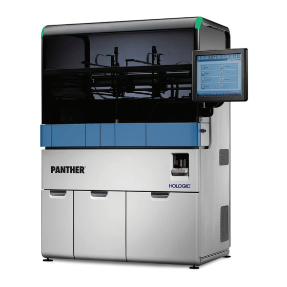
Page 57: Figure 4. Panther System
Overview used to direct the operation of the subsystems to perform the assay steps, as well as accommodating LIS connectivity and remote user access. The Panther System is composed of four main areas: Canopy Panther Upper Bay Panther Mid Bay Panther Lower Bay Figure 4. -
Page 58: Canopy
Overview Table 14. Panther System Components (Continued) Location Description Mid Bay Lower Bay Canopy Figure 5. Canopy Table 15. Canopy Location Descriptions Description Top Left LED Top Right LED Panther Top Canopy Panel Monitor Panther Left Canopy Door Panther Right Canopy Door ®... -
Page 59: Panther Upper Bay Components
Overview The smoked plexiglass canopy houses the pipettor architecture. The Touch-Screen Monitor, connected to the right side of the canopy, is used to navigate the Panther System Software. Panther Upper Bay Components The Panther Upper Bay consists of the following components:... -
Page 60: Reagent Bay
The Reagent Bay is a liquid-cooled storage bay that holds up to four (4) racks of reagents. The internal reagent barcode reader identifies the reagent racks and reagent bottles as they are loaded into the instrument. The reagents are housed in a cooled environment for extended stability. ® Panther System Operator’s Manual AW-17791-001 Rev. 002 (EN) -
Page 61: Panther Tip Drawer Module
The carousel holds up to four (4) bottles of TCR and four (4) bottles of Target Enhancer Reagent (TER). The TCR barcode reader scans all bottle positions in the TCR carousel, verifying reagent placement and validity. Note—Not all Aptima assays use TER. ® Panther System Operator’s Manual AW-17791-001 Rev. 002 (EN) -
Page 62: Panther Pipettor System
Panther Mid Bay Components The Panther Mid Bay consists of the following components: Incubators MTU Input Queue Distributor AMP Load Station HPA Load Station Magnetic Wash Stations Sample Mix Stations Luminometer Output Queue ® Panther System Operator’s Manual AW-17791-001 Rev. 002 (EN) -
Page 63: Figure 10. Panther Mid Bay
Table 17. Panther Mid Bay Descriptions Location Description Amp Load Station HPA Load Station Reagent Tip Eject Magnetic Parking Slot 1 Magnetic Parking Slot 2 Magnetic Wash Station 1 Magnetic Wash Station 2 Sample Mix Station ® Panther System Operator’s Manual AW-17791-001 Rev. 002 (EN) -
Page 64: Incubators
MTU before amplification; Cools the MTU after HPA and before entering the luminometer. Amplification Incubator (AMP)—Amplifies targets during TMA. Attached beneath the Amplification Incubator are the fluorometers used to detect fluorescent signals from real-time assays. ® Panther System Operator’s Manual AW-17791-001 Rev. 002 (EN) -
Page 65: Mtu Input Queue
Luminometer The Luminometer measures the chemiluminescent reaction triggered by the addition of Auto Detect fluids to each tube of the MTU. The luminescence is measured with a photomultiplier tube (PMT). ® Panther System Operator’s Manual AW-17791-001 Rev. 002 (EN) -
Page 66: Output Queue
Panther Waste Drawer Panther Universal Fluids Drawer NaOCl Bottle Vacuum System Figure 11. Panther Lower Bay Table 18. Panther Lower Bay Descriptions Location Description Power Supply Solid Waste Container Vacuum Pump ® Panther System Operator’s Manual AW-17791-001 Rev. 002 (EN) -
Page 67: Computer
Liquid Waste Filter Liquid Waste Bottle Computer Power Switch Computer The computer is housed in the lower left of the Panther System. The Panther System Software launches automatically once the computer is powered on. When powering on, ® Panther System Operator’s Manual... -
Page 68: Panther Waste Drawer
Overview turn on the Panther System before turning on the computer to avoid communication errors. Panther Waste Drawer The Panther Waste Drawer contains the Liquid Waste Container, Liquid Waste Filter, Coalescing Bottle, and Solid Waste Container. Liquid Waste Container The Liquid Waste Container, located in the front of the Waste Drawer, collects the liquid waste from the Magnetic Wash Station and the Output Queue. -
Page 69: Printer
Overview Printer The Panther System printer can be used to print all Panther System reports. It is possible to connect the printer to the system through the site's network. Contact Hologic personnel to assist with networking the printer. Panther System Software Overview Introduction The Panther System Software is provided for use with the system. -
Page 70: Login Screen
The buttons, status bars, and icons can be found grouped either in the Menu Bar or Status Panel or as an interactive item on every screen. ® Panther System Operator’s Manual AW-17791-001 Rev. 002 (EN) -
Page 71: Figure 14. Screen Locations (Example)
ID, status icons, the date and time, and the Print Screen button (see Status Panel on page 47). Tip Count The number of pipette tips remaining and the status of the Tip Drawers (see Tip Count on page 48). ® Panther System Operator’s Manual AW-17791-001 Rev. 002 (EN) -
Page 72: Menu Bar
State Indicator Indicator on page 134). Menu Bar The Menu Bar is located at the top of every screen. Use the buttons on the Menu Bar to navigate through the system software. ® Panther System Operator’s Manual AW-17791-001 Rev. 002 (EN) -
Page 73: Interactive Items
Additional interactive items are accessible on every screen. These items provide additional information required to operate the system. Table 22. Interactive Item Descriptions Status Bar Meaning of Information on Status Bar Screen Name Indicates the current screen displayed. ® Panther System Operator’s Manual AW-17791-001 Rev. 002 (EN) -
Page 74: Selection Button
The panel is composed of Status Bars, Status Icons, and additional items to provide information on inventory of consumables, system activity updates, username ID, and date/time. ® Panther System Operator’s Manual AW-17791-001 Rev. 002 (EN) -
Page 75: Status Panel Bars
Select this bar to access the Waste Management screen. Fluid Kit A Select this bar to access the Universal Fluid Bay screen. Fluid Kit B Select this bar to access the Universal Fluid Bay screen. ® Panther System Operator’s Manual AW-17791-001 Rev. 002 (EN) -
Page 76: Additional Status Panel Icons
LIS—The icon is displayed when the system is connected to an LIS. Remote Diagnostics—The icon is displayed when a Hologic specialist is connected to the system during a Remote Diagnostic Session. Selecting this icon transitions the operator to the PRO360°... -
Page 77: Additional Status Panel Items
The file will appear in Panther Images folder in the drive with the following naming convention: ScreenCapture_ YYYYMMDD_HHMMSS*.jpg *The date and time represent the time that the file was created. ® Panther System Operator’s Manual AW-17791-001 Rev. 002 (EN) -
Page 78: Panther System Software Screens
Overview Panther System Software Screens The following section provides an overview of the information and functions available on the following main screens. Desktop Waste Run Status LIS Configuration Shield Management Maintenance Login Test Orders Operator Management Activities Assay Messages Results... -
Page 79: Figure 18. Desktop Shield Screen (Example)
Figure 18. Desktop Shield Screen (Example) Table 27. Desktop Shield Screen Button Descriptions Button Description Panther Select this button to start the Panther System Software. Backup Select this button to access the database backup functionality (see Database Backup on page 211). -
Page 80: Messages Screen
The category of the message. The message severity can fall into one of the following categories: Error—System error occurred that requires operator intervention. Warning—System event occurred that may necessitate operator intervention. Info—Informational system message. ® Panther System Operator’s Manual AW-17791-001 Rev. 002 (EN) -
Page 81: Comments Screen
Remote Select this button to activate the PRO360° software. Diagnostics This task should be used in conjunction with Hologic Technical Support assistance as part of troubleshooting system issues. Refer to the Remote Diagnostics section for further information on how to perform this task (see Troubleshooting on page 254). -
Page 82: Pending Screen
The Pending button flashes yellow and System LEDs flash green when new pending notifications are generated. The red number on the Pending icon represents the number of notifications present on the screen. ® Panther System Operator’s Manual AW-17791-001 Rev. 002 (EN) -
Page 83: Tasks Screen
To access the Tasks screen, select the Tasks button on the Menu Bar. The Tasks screen automatically opens after logging into the system. Use the buttons on the Tasks screen to prepare the system for assay processing. ® Panther System Operator’s Manual AW-17791-001 Rev. 002 (EN) -
Page 84: Figure 22. Tasks Screen (Example)
Select this button to access the Waste Management screen (see Empty Waste on page 101). Perform Select this button to access the Maintenance Maintenance Activities screen (see Maintenance Activities Screen on page 190). ® Panther System Operator’s Manual AW-17791-001 Rev. 002 (EN) -
Page 85: Universal Fluid Bay Screen
The Universal Fluid Bay screen provides current inventory, expiration and kit validity information for loaded universal fluids. Refer to the bottle display for a status update when refreshing the fluid inventory. For more information, see Load Panther Universal Fluids on page 98. ® Panther System Operator’s Manual AW-17791-001 Rev. 002 (EN) -
Page 86: Waste Management Screen
Select the Empty Waste button on the Tasks screen (see Tasks Screen on page 56). Select the Waste inventory status panel (see Status Panel on page 47). The Waste Management screen provides the remaining capacity of the Panther System waste containers. Refer to the container display for a status update when refreshing the waste capacity. -
Page 87: Maintenance Activities Screen
To access the Maintenance Activities screen, select the Perform Maintenance button on the Tasks screen (see Tasks Screen on page 56). Refer to the Maintenance Activities screen for the status of maintenance tasks and for managing maintenance procedures. ® Panther System Operator’s Manual AW-17791-001 Rev. 002 (EN) -
Page 88: Figure 25. Maintenance Activities Screen (Example)
Select this button to access the Maintenance Task Details screen (see Maintenance Task Details Screen on page 191). Force Full Prime Select this button to perform a full prime (see Force Full Prime on page 106). ® Panther System Operator’s Manual AW-17791-001 Rev. 002 (EN) -
Page 89: Assay Reagent Bay Screen
Open the Reagent Bay Door. Use the Assay Reagent Bay screen during the assay reagent loading process. For more information, see Load Panther Assay Reagents on page 106. Figure 26. Assay Reagent Bay Screen (Example) ® Panther System Operator’s Manual AW-17791-001 Rev. 002 (EN) -
Page 90: Assay Reagent Loading Screen
Operators are automatically directed to this screen if there is an assay reagent kit-related error during the loading process. Refer to the Assay Reagent Loading screen for specific Panther assay reagent kit information. ® Panther System Operator’s Manual AW-17791-001 Rev. 002 (EN) -
Page 91: Sample Rack Bay Screen
Select the Load Samples button on the Tasks screen (see Tasks Screen on page 56). Select the Sample Rack graphics on the Run Status screen (see Run Status Screen on page 70). Open the Sample Bay Door. ® Panther System Operator’s Manual AW-17791-001 Rev. 002 (EN) -
Page 92: Figure 28. Sample Rack Bay Screen (Example)
Lane Scanner on the selected Sample Bay Lane. Assign Reagent Select this button to assign a reagent lane to be used Lane for processing the next sample rack that is loaded. ® Panther System Operator’s Manual AW-17791-001 Rev. 002 (EN) -
Page 93: Sample Rack Loading Screen
The operator can also navigate to the Sample Rack Loading screen for adding test orders for the entire Sample Rack, as well as designating STAT for all specimens in the Sample Rack. ® Panther System Operator’s Manual AW-17791-001 Rev. 002 (EN) -
Page 94: Figure 29. Sample Rack Loading Screen (Example)
Select this button to allow any specimen that has already been processed to be tested as designated (see Enable Detection and Flagging of Repeat Barcodes/Reject All Repeat Test Orders on page 225). ® Panther System Operator’s Manual AW-17791-001 Rev. 002 (EN) -
Page 95: Sample Details Screen
From the Sample Rack Loading screen, click on a tube (see Sample Rack Loading Screen on page 66). Refer to the Sample Details screen for test order status and for altering the test order assignment for the sample. ® Panther System Operator’s Manual AW-17791-001 Rev. 002 (EN) -
Page 96: Figure 30. Sample Details Screen (Example)
MTU time slot (see Scheduling STAT Test Orders on page 126). Add Test Order Select this button to add test orders to the sample. ® Panther System Operator’s Manual AW-17791-001 Rev. 002 (EN) -
Page 97: Run Status Screen
To access the Run Status screen, select the Run Status button on the Menu Bar (see Menu Bar on page 45). Use the Run Status screen to monitor reagents and samples during assay processing. Figure 31. Run Status Screen (Example) ® Panther System Operator’s Manual AW-17791-001 Rev. 002 (EN) -
Page 98: Table 39. Run Status Screen Descriptions
Assay Processing state. Time for Next Result—The time that the next result will be available. Time for Last Result—The time that the result of the last test order will be available. ® Panther System Operator’s Manual AW-17791-001 Rev. 002 (EN) -
Page 99: Test Orders Screen
Refer to the Test Orders screen for information on test orders. Use the filter categories at the top of the screen or select the column headers to sort the test orders as desired. Figure 32. Test Orders Screen (Example) ® Panther System Operator’s Manual AW-17791-001 Rev. 002 (EN) -
Page 100: Results Screen
Refer to the Results screen for test results information. Use the Filters button at the top of the screen or select the column headers to sort the results as desired. Figure 33. Results Screen (Example) ® Panther System Operator’s Manual AW-17791-001 Rev. 002 (EN) -
Page 101: Table 41. Results Screen Descriptions
Select this button to add a note for the selected invalid control or calibrator (see User Comment on page 154). * These buttons are only visible under certain system software configurations. ® Panther System Operator’s Manual AW-17791-001 Rev. 002 (EN) -
Page 102: Report Menu Screen
(see Printing Reports on page 163). Export Select this button to export the report as defined by the report criteria. It is also possible to export while viewing the report (see Exporting Reports on page 164). ® Panther System Operator’s Manual AW-17791-001 Rev. 002 (EN) -
Page 103: Administration Screen
Figure 35. Administration Screen (Example) Table 43. Administration Screen Button Descriptions Screen Buttons Description Data Select this button to access the Data Management Management screen (see Data Management Screen on page 77). ® Panther System Operator’s Manual AW-17791-001 Rev. 002 (EN) -
Page 104: Data Management Screen
Refer to the Data Management screen for purging the three (3) types of system logs and the results logs. Use the available buttons on the screen to complete the corresponding data management tasks. ® Panther System Operator’s Manual AW-17791-001 Rev. 002 (EN) -
Page 105: Figure 36. Data Management Screen (Example)
Results Config the database (see Auto Purge Log Configuration on page 216). Purge Activity Select this button to manually purge activity logs from the database (see Purge Logs on page 216). ® Panther System Operator’s Manual AW-17791-001 Rev. 002 (EN) -
Page 106: System Configuration Screen
Administration screen (see Administration Screen on page 76). Select any of the tabs on the User Configurable Settings menu to view the settings for the corresponding functional area. Figure 37. System Configuration Screen (Expanded Example) ® Panther System Operator’s Manual AW-17791-001 Rev. 002 (EN) -
Page 107: Lis Configuration Screen
To access the LIS Configuration screen, select the LIS Configuration button on the Administration screen (see Administration Screen on page 76). Refer to the LIS Configuration screen to adjust the LIS settings. ® Panther System Operator’s Manual AW-17791-001 Rev. 002 (EN) -
Page 108: Figure 38. Lis Configuration Screen-General Settings (Example)
Overview Figure 38. LIS Configuration Screen—General Settings (Example) ® Panther System Operator’s Manual AW-17791-001 Rev. 002 (EN) -
Page 109: Figure 39. Lis Configuration Screen-Serial Settings (Example)
Overview Figure 39. LIS Configuration Screen—Serial Settings (Example) Figure 40. LIS Configuration Screen—TCP/IP Settings (Example) ® Panther System Operator’s Manual AW-17791-001 Rev. 002 (EN) -
Page 110: Figure 41. Lis Configuration Screen-File Settings (Example)
236). These directories are only accessible by Hologic personnel. Save Select this button to save configurations. Start Select this button to enable LIS connection. Stop Select this button to disable LIS connection. ® Panther System Operator’s Manual AW-17791-001 Rev. 002 (EN) -
Page 111: Operator Management Screen
(see Deleting Operator Accounts on page 243). Change Password To access the Change Password window, select the Change Password button on the Administration screen (see Administration Screen on page 76). ® Panther System Operator’s Manual AW-17791-001 Rev. 002 (EN) -
Page 112: Quality Control Configuration Screen
Select this button to create a new external quality control. Edit Select a quality control from the table and then select this button to edit/view the information for the chosen external quality control. ® Panther System Operator’s Manual AW-17791-001 Rev. 002 (EN) - Page 113 Delete Select a quality control from the table and then select this button to delete the chosen external quality control from the table. ® Panther System Operator’s Manual AW-17791-001 Rev. 002 (EN)
-
Page 114: Reflex Testing Configuration Screen
Reflex Testing Configuration Screen To access the Reflex Testing Configuration screen, select the Reflex Testing Configuration button on the Administration screen (see Administration Screen on page 76). ® Panther System Operator’s Manual AW-17791-001 Rev. 002 (EN) -
Page 115: Figure 45. Reflex Testing Configuration Screen (Example)
Sample Rack loading that are to be assigned reflex test orders following testing. Save Select this button to save changes made to the reflex testing configuration settings. ® Panther System Operator’s Manual AW-17791-001 Rev. 002 (EN) -
Page 116: Assay Custom Cutoff Value Configuration Screen
To access the Help window, select the Help button on the Menu Bar (see Menu Bar on page 45). Select the Help button to access the section of the Panther System Operator’s Manual that refers to the current screen. Use the instructions in the manual for assistance or troubleshooting purposes. -
Page 117: Logoff/Shutdown Screen
To access the Logoff/Shutdown screen, select the Logoff button on the Menu Bar (see Menu Bar on page 45). Use the Logoff/Shutdown screen to log off the Panther System Software or to shut down the computer. Do not log off the system before shutting down. -
Page 118: Figure 47. Logoff/Shutdown Screen (Example)
Figure 47. Logoff/Shutdown Screen (Example) Table 52. Logoff/Shutdown Screen Buttons Screen Buttons Description Logoff Select this button to log off the Panther System Software (see Logoff on page 93). Instrument Select this button to shut down the computer (see Shutdown System Startup on page 92). -
Page 119: System Operation
To start the Panther System: 1. Make sure that there are no Sample or Reagent Racks onboard the system and that all doors, covers, and drawers are closed. Turn the Panther System on using the power switch on the rear left of the instrument. -
Page 120: Logoff
The Login screen opens. System tasks already in process continue when logged off. System Operation Warning—Do not re-use Tips, MTUs, Waste Bags, or Waste Covers. Use only tips, MTUs, and Waste Covers that are supplied by Hologic. Use of unapproved consumables may compromise assay or Panther System performance. -
Page 121: Load Tips
Tip Count status bar will provide a return time for when more tips will be needed to continue processing, if necessary. To load tips: 1. Perform one of the following tasks to initiate the load tips process: ® Panther System Operator’s Manual AW-17791-001 Rev. 002 (EN) -
Page 122: Figure 49. Tip Loading Management Window (Example)
2. Select the Unlock button for the desired Tip Drawer(s). The Tip Drawer(s) will have automatically unlocked if all tips were depleted. The selected drawer(s) will unlock and will be available for loading. ® Panther System Operator’s Manual AW-17791-001 Rev. 002 (EN) -
Page 123: Table 53. Tip Replacement Options
5. The drawer(s) lock and the system updates the tip count. Ensure that all tip rack icons on the screen have the appropriate colored borders, indicating successful replacement, before proceeding. 6. Select Accept. The window closes. ® Panther System Operator’s Manual AW-17791-001 Rev. 002 (EN) -
Page 124: Load Mtus
If the entire box is not loaded, some MTUs will remain in the box. Do not overload the MTU Drawer. These extra MTUs can be loaded later. Do not remove unused MTUs from the box. d. Smoothly slide the MTU box backward, away from the instrument. ® Panther System Operator’s Manual AW-17791-001 Rev. 002 (EN) -
Page 125: Load Universal Fluids
NaOCl Bottle is not kitted with Fluid Kit A or B. The NaOCl Bottle needs to be refilled with 5.0%–7.0% sodium hypochlorite (NaOCl solution) when replacing one (1) or both fluid kits. ® Panther System Operator’s Manual AW-17791-001 Rev. 002 (EN) -
Page 126: Replace Panther Universal Fluids
Fluids Drawer. An invalid fluid bottle will generate a red light. The LED light is off for an empty bottle position or an improperly aligned RFID tag. ® Panther System Operator’s Manual AW-17791-001 Rev. 002 (EN) -
Page 127: Figure 50. Bottle Status Panel (Example)
A Completing Universal Fluid Inventory window opens with a progress bar for verification of the fluids inventory. The Panther Universal Fluid Bay screen remains on display after completion of this task. ® Panther System Operator’s Manual AW-17791-001 Rev. 002 (EN) -
Page 128: Empty Waste
DI water. Warning—Do not reuse Waste Bags and Waste Covers. Use only Waste Bags and Waste Covers supplied by Hologic. Use of unapproved Waste Bags and Waste Covers can interfere with assay or system performance. Corrosive Warning—The Liquid Waste Bottle contains sodium hypochlorite solution. - Page 129 Warning—Tilt the Liquid Waste Container appropriately to ensure that no waste enters the tubing within the container. Use the numerous holds on the container to aide in pouring of the contents. ® Panther System Operator’s Manual AW-17791-001 Rev. 002 (EN)
-
Page 130: Figure 51. Disposing Of Liquid Waste Container Contents (Example)
14. Close the Waste Drawer. The drawer locks and the vacuum turns on. A progress bar remains onscreen until the system can complete verification of the waste inventory and vacuum pressure. ® Panther System Operator’s Manual AW-17791-001 Rev. 002 (EN) -
Page 131: Perform Maintenance
Figure 52. Maintenance Activities Screen (Example) It is not possible to process samples once a required task becomes past due. Refer to the General Maintenance Information section for guidance on completing Panther System maintenance tasks (see General Maintenance Information on page 189). -
Page 132: Prime Criteria
Before initiating the procedure, the operator needs to ensure adequate fluid and waste inventory for assay processing following prime. Make the necessary calculations to ensure that there will be enough fluid and waste inventory remaining ® Panther System Operator’s Manual AW-17791-001 Rev. 002 (EN) -
Page 133: Prime Procedure
Processing states and a Panther Reagent Bay Lane is available for loading. Specimens associated with a reagent kit must be pipetted before the assay reagent kit expiration time. Master Lot Setup Register the assay reagent master lot information before loading an assay reagent ® Panther System Operator’s Manual AW-17791-001 Rev. 002 (EN) -
Page 134: Add A New Master Lot
Master Lot. The barcodes can be scanned in any order. As each barcode is scanned, the barcode populates the appropriate text box in the New/Activate Master Lot window. 5. Select Accept. ® Panther System Operator’s Manual AW-17791-001 Rev. 002 (EN) -
Page 135: Inactivate A Master Lot
1. Select the Load Assay Reagents icon on the Tasks screen. The Panther Assay Reagent Bay screen opens. 2. At the bottom of the Panther Assay Reagent Bay screen, select New/Activate Lot. A New/Activate Master Lot screen opens. ® Panther System Operator’s Manual AW-17791-001 Rev. 002 (EN) -
Page 136: Reagent Kit Date Extension
Reagent Kit Date Extension Extend the expiration date for an assay reagent Master Lot when directed by Hologic. Detailed instructions for how to extend the Master Lot expiration date will be provided by Hologic. The date extension procedure is performed through the Panther Assay Reagent Bay screen using the Date Extend Lot button located on the New/Activate Master Lot Barcode window. -
Page 137: Loading Panther Assay Reagents
System Operation Caution—Inspect Assay Reagents for foam, bubbles, and undissolved particles before loading them on the Panther System. Do not use reagents with foam, bubbles, or undissolved particles in the Panther System. 4. Slide the bottles into the correct position in an appropriately sized Reagent Rack. -
Page 138: Figure 56. Supplemental Reagent Information Window (Example)
The Supplemental Reagent Information window opens for the operator to enter the reconstitution dates and TCR additive for each new kit that was loaded, as necessary. Figure 56. Supplemental Reagent Information Window (Example) ® Panther System Operator’s Manual AW-17791-001 Rev. 002 (EN) -
Page 139: Unloading Panther Assay Reagents
Do not remove racks when the lane LED is red and the rack graphic on the screen is yellow with a red border. To unload Assay Reagents: 1. Open the Reagent Bay Door. ® Panther System Operator’s Manual AW-17791-001 Rev. 002 (EN) -
Page 140: Load Samples
1. Select the Load Samples icon on the Tasks screen. The Sample Rack Bay screen opens. 2. At the bottom of the Sample Rack Bay screen, select New Ctrl/Cal Lot. A Control/Calibrator Lot Entry window opens. ® Panther System Operator’s Manual AW-17791-001 Rev. 002 (EN) -
Page 141: Controls/Calibrators Setup
Sample Bay. Specimens will be pipetted when one of the following two (2) conditions have been met: ® Panther System Operator’s Manual AW-17791-001 Rev. 002 (EN) -
Page 142: Control/Calibrator Processing
To require a new set of controls/calibrators: 1. From the Panther Assay Reagent Bay screen, select Run New Ctrls/Cals. The Run New Ctrls/Cals window opens. ® Panther System Operator’s Manual AW-17791-001 Rev. 002 (EN) -
Page 143: Loading Samples Into Sample Racks
To load samples into Sample Racks: 1. Obtain a clean Sample Rack and position the rack in the Rack Loading Tray on a clean work surface. ® Panther System Operator’s Manual AW-17791-001 Rev. 002 (EN) -
Page 144: Sample Defaults
Processing states. Adding an Assay to the Sample Defaults To add an assay test to the Sample Defaults: 1. From the Sample Defaults panel of the Sample Rack Bay screen, select Set. ® Panther System Operator’s Manual AW-17791-001 Rev. 002 (EN) -
Page 145: Altering Replicate Count For Sample Defaults
Altering Replicate Count for Sample Defaults To alter the number of replicates tested for each of the selected default assays: 1. From the Sample Defaults panel of the Sample Rack Bay screen, select Set. ® Panther System Operator’s Manual AW-17791-001 Rev. 002 (EN) -
Page 146: Deleting An Assay Test From The Sample Defaults
The Sample Defaults window opens with current default assay types and test replicate settings. 2. From the Sample Defaults window, select More. The Sample Defaults screen expands with a display of sample prefix and suffix information fields. ® Panther System Operator’s Manual AW-17791-001 Rev. 002 (EN) -
Page 147: Figure 62. Expanded Sample Defaults Window (Example)
Enable Worklist ID Suffix configuration is enabled (see Specimen Loading on page 224). After processing, these samples will be organized under the entered ID suffix in results reports. Select Clear Suffix to remove the content of the cells. ® Panther System Operator’s Manual AW-17791-001 Rev. 002 (EN) -
Page 148: Manually Download Test Orders
Sample Rack Bay screen and then selecting Change Scan Lane. The Sample Barcode Reader will automatically scan the Sample Rack and sample barcodes as the rack is loaded. Samples are registered by the system ® Panther System Operator’s Manual AW-17791-001 Rev. 002 (EN) -
Page 149: Assigning A Reagent Lane For Aptima Assays
(see Sample Defaults on page 117). 2. From the Sample Rack Bay screen, select the Assign Reagent Lane button. The Select Reagent Lanes window opens. Figure 63. Select Reagent Lanes Window (Example) ® Panther System Operator’s Manual AW-17791-001 Rev. 002 (EN) -
Page 150: Editing Specimen Test Orders
The Sample Details screen opens with the current test orders for the selected specimen tube. 3. Select Add Test Order at the bottom of the screen. The Add Test Orders window opens. ® Panther System Operator’s Manual AW-17791-001 Rev. 002 (EN) -
Page 151: Figure 64. Add Test Orders Window (Example)
11. Type in the desired number of replicates to be tested with the chosen assay type and select OK when finished. The Replicates field updates with the desired replicate number. 12. Select Accept to accept the chosen test order(s) and replicate count. ® Panther System Operator’s Manual AW-17791-001 Rev. 002 (EN) -
Page 152: Deleting A Test Order
3. Select OK to confirm the deletion. The test order is deleted. To delete a test order through the Sample Rack Loading screen: 1. From the Sample Rack Loading screen, select Remove All Test Orders. ® Panther System Operator’s Manual AW-17791-001 Rev. 002 (EN) -
Page 153: Scheduling Stat Test Orders
3. From the Set STAT for Rack window, select the YES button to continue. STAT designation is applied to all specimens in the sample rack in the Sample Rack Bay screen. 4. Repeat Steps 1–3 to set STAT priority for any additional sample racks. ® Panther System Operator’s Manual AW-17791-001 Rev. 002 (EN) -
Page 154: Running Controls/Calibrators As Specimens
System Operation Running Controls/Calibrators as Specimens To process Hologic controls/calibrators as specimen tubes (i.e., only report results of the control or calibrator and not use them to validate an assay kit or associated specimen): 1. From the Sample Rack Bay screen, do one of the following: Double-click the onscreen image of the desired Sample Rack. -
Page 155: Apply Dilution Factors
Apply Dilution Factors Note—For additional information on custom dilution factors, refer to the appropriate Panther System Software Application Sheet. To add 1:3 or 1:100 dilution factors to quantitative assay test orders so that the final results are listed at original concentrations: 1. -
Page 156: Unloading Sample Racks
Steps 2 and 3 are met. 6. If necessary, load fresh Sample Racks into the empty Sample Bay Lanes (see Loading Sample Racks on page 121). 7. Close the Sample Bay Door. ® Panther System Operator’s Manual AW-17791-001 Rev. 002 (EN) -
Page 157: Initiating Assay Processing
Monitoring the System through Hardware Use the LEDs and the system alarm to help monitor the system status. Monitor the information provided by these items to ensure the proper functionality of the system. ® Panther System Operator’s Manual AW-17791-001 Rev. 002 (EN) -
Page 158: System Leds
Reagent Bay Lane is available for loading. Green Green Reagents are loaded and available for use. Reagents in rack are currently being pipetted. Do not remove Reagent Rack from this lane. ® Panther System Operator’s Manual AW-17791-001 Rev. 002 (EN) -
Page 159: Sample Bay Lane Leds
These LEDs change color according to the following table. Table 59. Tip Drawer, TCR Door, and MTU Input Queue LED Status Color Legend LED Color Meaning Green The drawer or door is unlocked. The drawer or door is locked. ® Panther System Operator’s Manual AW-17791-001 Rev. 002 (EN) -
Page 160: System Alarm
The button, located in the Menu Bar, displays the number of reflex test orders that require the user to reload the associated specimen tube. This button flashes yellow when reflex test orders remain on the Test Orders screen. ® Panther System Operator’s Manual AW-17791-001 Rev. 002 (EN) -
Page 161: Monitoring The State Indicator
The system is in this state after a Instrument currently prime has been initiated priming the fluid manually or automatically. lines. The operator cannot perform waste or fluid-related tasks while the system is in this state. ® Panther System Operator’s Manual AW-17791-001 Rev. 002 (EN) - Page 162 Save configuration settings. Exit continues to this state through the have access to Logoff/Shutdown screen, via data while in Power Save configuration this state. settings, or by loading or removing a Reagent Rack. ® Panther System Operator’s Manual AW-17791-001 Rev. 002 (EN)
-
Page 163: Monitoring The Status Panel
Monitoring the Status Panel Monitor the Status Panel for system activities, consumable inventory, and modules associated with the icon. ® Panther System Operator’s Manual AW-17791-001 Rev. 002 (EN) -
Page 164: Status Panel
Waste Drawer. The status bar turns red when the Waste Drawer is open. The status bar changes to yellow when the Waste capacity is below the configurable Waste Threshold (see Threshold Management on page 220). ® Panther System Operator’s Manual AW-17791-001 Rev. 002 (EN) -
Page 165: System Activity Updates
Unmarked icons indicate that the component is functioning normally. ® Panther System Operator’s Manual AW-17791-001 Rev. 002 (EN) -
Page 166: Table 63. Status Icon Descriptions
LIS. The icon will disappear if the LIS connection has been disabled. Remote Diagnostics—The icon is displayed when a Hologic specialist is connected to the system during a Remote Diagnostic Session. Selecting this icon transitions the operator to the PRO360° Software window. -
Page 167: Monitoring Pending Tasks
Panther Assay Reagent Bay Screen Monitor reagent loading and assay reagent kit usage on the Panther Assay Reagent Bay screen. The reagent lane graphics on the screen update according to the color legends below. ® Panther System Operator’s Manual AW-17791-001 Rev. 002 (EN) -
Page 168: Assay Reagent Loading Screen
Do not remove the Reagent Rack from this lane. Invalid reagent. Assay Reagent Loading Screen The Assay Reagent Loading screen, accessible through the Panther Assay Reagent Bay screen, provides detailed information on the selected assay reagent kit. ® Panther System Operator’s Manual AW-17791-001 Rev. 002 (EN) -
Page 169: Run Status Screen
Refer to the screen for test order information, including order timing, status, assay types, and chosen analyte types. ® Panther System Operator’s Manual AW-17791-001 Rev. 002 (EN) -
Page 170: Viewing Test Orders
Test Order Status The test order status is documented in the Status column on the Test Orders screen. Once the test order has been pipetted from the sample tube, the test ® Panther System Operator’s Manual AW-17791-001 Rev. 002 (EN) -
Page 171: Monitoring Loaded Specimen Status
Red Border Do not remove the Sample Rack from this lane. Red Rack Invalid Sample Rack entry. Gray No Sample Rack is loaded. White No test order for the loaded sample. ® Panther System Operator’s Manual AW-17791-001 Rev. 002 (EN) -
Page 172: Run Status Screen
Use the Run Status screen to monitor sample status and run processing for samples currently loaded on the system. The panels on the Run Status screen provide information for the loaded samples, results timing, assay reagents, and control/calibrator status. ® Panther System Operator’s Manual AW-17791-001 Rev. 002 (EN) -
Page 173: Specimen Status
Orders, and Sample Details screens. The Status field is updated depending on the current status of the specimens. The status categories listed in this column are defined in the table below. ® Panther System Operator’s Manual AW-17791-001 Rev. 002 (EN) -
Page 174: Figure 72. Sample Status Locations (Example)
Specimen is loaded on the system. Scheduled Test order has been scheduled for the loaded specimen. Pipetted Test order has been pipetted from the sample tube. In Process Test order for specimen is currently being processed. ® Panther System Operator’s Manual AW-17791-001 Rev. 002 (EN) -
Page 175: Specimens Panel
Test Request Received from LIS field is populated only when loaded specimens have not been assigned a test order. The graphics for samples without test orders appear as white on the Run Status screen. ® Panther System Operator’s Manual AW-17791-001 Rev. 002 (EN) -
Page 176: Monitoring Control/Calibrator Status
The control/calibrator set status can also be monitored from the Assay Reagents panel on the Run Status screen. The Expiration column displays the expiration countdown time of the control/calibrator set associated with the assay reagent kit. ® Panther System Operator’s Manual AW-17791-001 Rev. 002 (EN) -
Page 177: Monitoring Results Timing
LIS status, rack position and worklist ID. The Sample Curve Report is available depending on certain software configurations. ® Panther System Operator’s Manual AW-17791-001 Rev. 002 (EN) -
Page 178: Results Information
Worklist ID—ID number associated with all samples that were tested against the same set of controls/calibrators. The worklist ID follows the naming convention: XXXXX[Serial Number]- YYYYMMDD[Date a ]-XX[2digitSeqNum b ] ® Panther System Operator’s Manual AW-17791-001 Rev. 002 (EN) -
Page 179: Sample Curve Report
1. From the Results screen, select the row of the test order. 2. Select Curve Data. A window opens that contains the Sample Curve Report. Figure 78. Sample Curve Report (Example) ® Panther System Operator’s Manual AW-17791-001 Rev. 002 (EN) -
Page 180: Result Details
Universal Fluids—The Fluid Kit (A or B) that was used to process the test order. MTU ID—The identification number of the MTU that the test order was pipetted into. Position in MTU—The tube position of the MTU (1-5) that the test order was pipetted into. ® Panther System Operator’s Manual AW-17791-001 Rev. 002 (EN) -
Page 181: User Comment
Select Filters on the top left of the table to filter the display so that the desired information is shown. After selecting Filters, select the appropriate button and provide the necessary information. Filter categories can be used in combination. ® Panther System Operator’s Manual AW-17791-001 Rev. 002 (EN) -
Page 182: Verifying Results
3. Select the sample ID field to use the virtual keyboard to enter the sample ID for the selected specimen. Enter the information on the virtual keyboard and select OK when finished. 4. Select Accept. The Results or Test Orders screen updates to reflect the change. ® Panther System Operator’s Manual AW-17791-001 Rev. 002 (EN) -
Page 183: Data Export
The USB flash memory drive must not have pre-loaded software. The USB flash memory drive must be dedicated for use with Panther System files. Do not use the designated USB flash memory drive with other file types. Exporting to a USB Flash Drive 1. -
Page 184: Exporting Raw Data
Export LIS data for the selected test results from the Results screen. If the Enable Result Verification configuration is enabled, LIS results cannot be exported until they have been verified (see Enable Result Verification on page 227). ® Panther System Operator’s Manual AW-17791-001 Rev. 002 (EN) -
Page 185: Sending Results To Lis
1. From the Results screen, select the row(s) of the desired result(s). Ensure results are verified prior to sending if needed (see Verifying Results on page 155). The Send results to LIS button will be enabled. ® Panther System Operator’s Manual AW-17791-001 Rev. 002 (EN) -
Page 186: Export Viral Data
This section contains descriptions on how to create reports from the functionality on the Report Menu screen. Use the filters for each of the available report types to generate a report that contains the needed information. ® Panther System Operator’s Manual AW-17791-001 Rev. 002 (EN) -
Page 187: Table 71. Reports
System Operation Select the Reports button on the Menu Bar to access the Report Menu screen. All reports can be created from this screen. The following table describes the reports available through the Panther System Software: Table 71. Reports Report... - Page 188 (see Test Count Report on page 185). Worklist Lot Report Contains the assay reagent and fluid lot information for all tests within the selected worklist (see Worklist Lot Report on page 186). ® Panther System Operator’s Manual AW-17791-001 Rev. 002 (EN)
-
Page 189: Selecting Reports
4. After supplying the parameter information, select View at the bottom of the Report Menu screen to open the report. The selected report window opens. Navigate the report by using the navigation bar located at the bottom of each report. Refer to the Navigating Reports section ® Panther System Operator’s Manual AW-17791-001 Rev. 002 (EN) -
Page 190: Navigating Reports
Navigating Reports All reports contain a Report Navigation Bar at the bottom of each report. Figure 82. Panther System Report Navigation Bar Use the navigation bar to assist in viewing and handling the report. When done working with the report, use the buttons on the Menu Bar to return to other system tasks. -
Page 191: Exporting Reports
Report Type File Name Activity Log Report ActivityYYYYMMDD-HHMMSS*.pdf Assay Reagent Report AssayReagentYYYYMMDD-HHMMSS*.pdf Configuration Report ConfigurationYYYYMMDD-HHMMSS*.pdf Diagnostics Log Report DiagnosticsYYYYMMDD-HHMMSS*.pdf Exceptions by Worklist ExceptionsWorklistYYYYMMDD- Report HHMMSS**.pdf Exceptions Report ExceptionsYYYYMMDD-HHMMSS*.pdf Levey-Jennings Report LeveyJenningsYYYYMMDD-HHMMSS*.pdf ® Panther System Operator’s Manual AW-17791-001 Rev. 002 (EN) -
Page 192: Reports
Creation Date panel to generate a report that contains all activities that were performed over the selected date range. Once the filter has been updated, select View, Print, or Export as desired to access the Activity Log Report. ® Panther System Operator’s Manual AW-17791-001 Rev. 002 (EN) -
Page 193: Assay Reagent Report
Leaving the cell blank will produce a report that includes all valid assay reagent kits that have been loaded on the system. Select View, Print, or Export as desired to access the Assay Reagent Report. ® Panther System Operator’s Manual AW-17791-001 Rev. 002 (EN) -
Page 194: Configuration Report
Figure 84. Assay Reagent Report (Example) Configuration Report Select Configuration Report and select View, Print, or Export as desired to access the Configuration Report. ® Panther System Operator’s Manual AW-17791-001 Rev. 002 (EN) -
Page 195: Diagnostics Log Report
Hologic Technical Support can provide guidance on how to set the specifications in order to produce a log report that is needed for any instrument troubleshooting (see Appendix D. -
Page 196: Table 75. Diagnostics Log Report-Report Parameters
Check the Priority cell and then check the cell of the system message category desired. Event ID Check the Event ID cell and enter the event ID for the desired message in the open field. ® Panther System Operator’s Manual AW-17791-001 Rev. 002 (EN) -
Page 197: Exceptions By Worklist Report
Filter Description Worklist ID Select the Worklist ID from the table. Completion Date Select the From and the To fields and choose the beginning and end dates of the desired range. ® Panther System Operator’s Manual AW-17791-001 Rev. 002 (EN) -
Page 198: Exceptions Report
It is possible to use only the Completion Date, Sort By, and Assay filter categories to refine the report. All five (5) filter categories can be used in conjunction to further refine the ® Panther System Operator’s Manual AW-17791-001 Rev. 002 (EN) -
Page 199: Table 77. Exceptions Report-Report Parameters
Sample ID Check the cell and enter the SID in the Sample ID field. Verified Check the cell and choose either the Yes or No cells as appropriate for the filter. ® Panther System Operator’s Manual AW-17791-001 Rev. 002 (EN) -
Page 200: Levey-Jennings Report
EQC with a configured target mean and standard deviation. Once the filters have been updated, select View, Print, or Export as desired to access the Levey-Jennings Report. ® Panther System Operator’s Manual AW-17791-001 Rev. 002 (EN) -
Page 201: Table 78. Levey-Jennings Report-Report Parameters
Levey-Jennings chart. Select No to separate the same chart the data into multiple charts organized by the master lot used to process the control or calibrator. ® Panther System Operator’s Manual AW-17791-001 Rev. 002 (EN) -
Page 202: Lot Search Report
Select Lot Search Report and enter the Lot Field on the right of the Report Menu screen to generate a Lot Search Report. Enter the lot number of one of the following materials: Master Lot MTU Lot ® Panther System Operator’s Manual AW-17791-001 Rev. 002 (EN) -
Page 203: Maintenance Checklist
Report Menu screen for a checklist with the completed maintenance tasks for the selected month. Select View, Print, or Export as desired to access the Maintenance Checklist. ® Panther System Operator’s Manual AW-17791-001 Rev. 002 (EN) -
Page 204: Maintenance Log Report
Once the filter has been updated, select View, Print, or Export as desired to access the Maintenance Log Report. ® Panther System Operator’s Manual AW-17791-001 Rev. 002 (EN) -
Page 205: Messages Log Report
(3) filter categories can be used together to further refine the report, if necessary. Make a selection in the categories of choice and check the correct cells as appropriate to generate a report that contains all system messages that match the filter specifications. ® Panther System Operator’s Manual AW-17791-001 Rev. 002 (EN) -
Page 206: Table 82. Messages Log Report-Report Parameters
Critical Fatal Undefined Check the cell of the system message category desired. Event ID Check the cell and enter the event ID of the desired message in the Event ID field. ® Panther System Operator’s Manual AW-17791-001 Rev. 002 (EN) -
Page 207: Prevalence Report
Completion Date Select the From field and choose the beginning date of the range desired. The To field automatically updates to cover the period one (1) month from the selected date. ® Panther System Operator’s Manual AW-17791-001 Rev. 002 (EN) -
Page 208: Results By Worklist Report
Once the Worklist ID has been selected, select View, Print, or Export as desired to access the Results by Worklist Report. Table 84. Results by Worklist Report—Report Parameters Filter Description Worklist ID Select the Worklist ID from the table. ® Panther System Operator’s Manual AW-17791-001 Rev. 002 (EN) -
Page 209: Results Report
Figure 95. Results by Worklist Report (Example) Results Report Select Results Report and generate a Results Report based upon the five (5) filter categories: Completion Date Assay Sort By ® Panther System Operator’s Manual AW-17791-001 Rev. 002 (EN) -
Page 210: Table 85. Results Report-Report Parameters
Sample ID Check the cell and enter the SID in the Sample ID field. Verified Check the cell and choose either the Yes or No cells as appropriate for the filter. ® Panther System Operator’s Manual AW-17791-001 Rev. 002 (EN) -
Page 211: Sample Audit Report
View, Print, or Export as desired to access the Sample Audit Report. Table 86. Sample Audit Report—Report Parameters Filter Description Sample ID Enter the SID in the Sample ID field. ® Panther System Operator’s Manual AW-17791-001 Rev. 002 (EN) -
Page 212: Test Count Report
Table 87. Test Count Report—Report Parameters Filter Description Test Count Select the From and the To fields and choose the Report Date beginning and end dates of the desired range. Range ® Panther System Operator’s Manual AW-17791-001 Rev. 002 (EN) -
Page 213: Worklist Lot Report
Once the Worklist ID has been chosen, select View, Print, or Export as desired to access the Worklist Lot Report. Table 88. Worklist Lot Report—Report Parameters Filter Description Worklist ID Select the Worklist ID from the table. ® Panther System Operator’s Manual AW-17791-001 Rev. 002 (EN) -
Page 214: System Shutdown
The shut down buttons are not available when the system is in the Initialization, Maintenance, or Assay Processing states. To shut down the Panther System: 1. Unload all Sample Racks (see Unloading Sample Racks on page 129) and all assay reagents from the system (see Unloading Panther Assay Reagents on page 112). -
Page 215: Figure 100. Shutdown Confirmation Window
System Operation Figure 100. Shutdown Confirmation Window 4. Select Yes to confirm shutdown. The Panther System Software properly shuts down to the Desktop Shield screen. 5. From the Desktop Shield screen, select the shutdown icon. The computer properly shuts down. -
Page 216: Maintenance
General Maintenance Information The system must be maintained regularly in order to ensure reliable performance. Perform maintenance on the system as outlined in this section. Authorized Hologic personnel will perform supplemental preventative maintenance as scheduled. Warning—Follow Universal Precautions when performing all maintenance activities on the Panther System. -
Page 217: Maintenance Activities Screen
Activities screen provides times when scheduled maintenance activities are due and when automated maintenance tasks are set to proceed. Select the Perform Maintenance icon on the Tasks screen to access the Maintenance Activities screen (see Tasks Screen on page 56). ® Panther System Operator’s Manual AW-17791-001 Rev. 002 (EN) -
Page 218: Maintenance Task Details Screen
Select a maintenance task on the Maintenance Activities screen and then select Details to access the Maintenance Task Details screen. Select Done to return to the Maintenance Activities screen. ® Panther System Operator’s Manual AW-17791-001 Rev. 002 (EN) -
Page 219: Set Maintenance Tasks To Required
To set a maintenance task to a required interval: 1. From the Maintenance Activities screen, select the maintenance task to be scheduled. 2. Select Edit. The Edit Maintenance Task screen opens. ® Panther System Operator’s Manual AW-17791-001 Rev. 002 (EN) -
Page 220: Schedule An Automated Maintenance Task
Setup or Ready state. To schedule an automated maintenance task: 1. From the Maintenance Activities screen, select the maintenance task to be automated. ® Panther System Operator’s Manual AW-17791-001 Rev. 002 (EN) -
Page 221: Tracking The Maintenance Schedule
Figure 105. Maintenance Table (Example) The Auto Start column applies to maintenance tasks that have been scheduled to proceed automatically. ® Panther System Operator’s Manual AW-17791-001 Rev. 002 (EN) -
Page 222: Maintenance Reports
The information is then associated with the task record and can be viewed on the Maintenance Checklist and on the Maintenance Log Report through the Reports screen. Recommended Cleaning Agents The following table lists the cleaning agents recommended for maintenance procedures. ® Panther System Operator’s Manual AW-17791-001 Rev. 002 (EN) -
Page 223: Table 90. Recommended Cleaning Agents
70% isopropyl alcohol wipes Sodium 2.5%–3.5% Laboratory: Cleaning work surfaces. Hypochlorite sodium Panther System: Cleaning the external work Solutions hypochlorite or surfaces and the surfaces of the following prepared Bleach instrument components: Reagent Shield, Enhancer Reagent Bay, Sample Bay, Sample Shield,... - Page 224 Clean Workspace on page 199) Advanced Endozime Mag Wash Clean task (see Mag Wash Clean Cleaning Solution on page 200) Solution Replacing Mag Wash Cleaning Solution (see Replace Mag Wash Cleaning Solution on page 209) ® Panther System Operator’s Manual AW-17791-001 Rev. 002 (EN)
-
Page 225: Preparing Sodium Hypochlorite Solution
Verify that the following environmental specifications are met before initiating testing. Table 91. Environmental Specifications Laboratory Specification Low Range High Range Temperature (°C) 15 °C 30 °C Relative Humidity (%) ® Panther System Operator’s Manual AW-17791-001 Rev. 002 (EN) -
Page 226: Preparing A Clean Workspace
(optional). Checking for Leaks and Spills Caution—Do not operate the Panther System if it is suspected or found that liquid has leaked, spilled, or overflowed onto electrical components. Contact Hologic Technical Support. Do not try to clean the inaccessible parts of the system without proper assistance. -
Page 227: Mag Wash Clean
As part of the resolution for Mag Wash station errors If Magnetic Wash aspiration errors occur, perform this procedure following assay processing or as directed by Hologic Technical Support. Table 92. Example Mag Wash Maintenance Tasks Cleaning Schedules Testing Days per Week... -
Page 228: Clean The Sample Shield
Clean the Sample Shield weekly in order to properly maintain a clean environment within the system. Perform this task when the instrument is in the Setup or Ready states. Complete the procedure as part of Monthly Maintenance and additionally as needed. ® Panther System Operator’s Manual AW-17791-001 Rev. 002 (EN) -
Page 229: Pc Reboot Maintenance
4. Select Start to shut down and restart the computer. The computer safely shuts down and restarts. 5. Login to the software as directed in the Login section (see Login on page 92). ® Panther System Operator’s Manual AW-17791-001 Rev. 002 (EN) -
Page 230: Monthly Maintenance
Maintenance Monthly Maintenance Clean the entire Panther System once a month to maintain a clean environment within the instrument. The procedure takes approximately 45 minutes to complete. Perform this task when the instrument is in the Setup or Ready state. -
Page 231: Step 3. Clean The Reagent Bay
To clean the Sample Bay: 1. Open the TCR Door, Sample Bay Door, and the Right Canopy Door. 2. Remove the Advanced Cleaning solution (Mag Wash) from the cleaning solution holder. ® Panther System Operator’s Manual AW-17791-001 Rev. 002 (EN) - Page 232 20. Place the cleaned and dry TCR Bottle Adapters in the appropriate positions of the TCR Carousel. 21. Place the bottle of Advanced Cleaning solution (Mag Wash) back into the cleaning solution holder. ® Panther System Operator’s Manual AW-17791-001 Rev. 002 (EN)
-
Page 233: Step 5. Clean The Panther Universal Fluid Drawer
Fluid Kit B apart so that they can be reloaded into the drawer after cleaning. 3. Inspect the NaOCl bottle and the Universal Fluid drawer for any liquid spills. If any leaks are found, contact Hologic Technical Support. 4. Clean all fluid connections and caps with a wipe moistened with 2.5%–3.5% sodium hypochlorite solution or prepared Bleach Enhancer solution. -
Page 234: Step 6. Clean The Panther Waste Drawer
3. Dispose of the MTU Waste Bag and MTU Waste Cover according to laboratory policies. 4. Inspect the drawer for any liquid spills. If any spills are found, contact Hologic Technical Support. 5. Clean the Waste Drawer and Solid Waste Container surfaces thoroughly with a wipe moistened with 2.5%–3.5% sodium hypochlorite solution or prepared... -
Page 235: Figure 107. Disposing Of Liquid Waste Container Contents (Example)
10. Slide a new Waste Cover over the Waste Bag on the back of the container. 11. Inspect the Liquid Waste Container for cracks and smooth magnet movement. If cracks are found, contact Hologic Technical Support. 12. Remove the bottle cap from the Liquid Waste Container and slowly pour the contents of the Liquid Waste Container into the appropriate designated sink or receptacle. -
Page 236: Step 7. Clean The External Surfaces
Replace Mag Wash Cleaning Solution Replace the Advanced Cleaning Solution after the system generates a message that the task is overdue. The system automatically tracks the volume of the cleaning solution and ® Panther System Operator’s Manual AW-17791-001 Rev. 002 (EN) -
Page 237: Idle Maintenance
Remove Biohazard Waste prior to expected idle periods Prime the system at least twice per week Continue to perform the Mag Wash Clean procedure as recommended Beyond 4 Weeks Contact Hologic Technical Support for additional maintenance information. ® Panther System Operator’s Manual... -
Page 238: Clean Sample Racks And Reagent Racks
Do not save a copy of the database after a database corruption event occurs. To back up the database: 1. Shut down the Panther System (see System Shutdown on page 187). 2. Start up the Panther System (see System Startup on page 92). The Desktop Shield screen opens. -
Page 239: Database Restore
Hologic authorized personnel. Only administrators should perform this task. To restore the database: 1. Shut down the Panther System (see System Shutdown on page 187). 2. Start up the Panther System (see System Startup on page 92). The Desktop Shield screen opens. - Page 240 (.bak) to be deleted, and select OK. 6. Select Execute. The software deletes the selected database file. The screen transitions back to the Desktop Shield screen following completion of the task. Select Panther to initiate the Panther System Software. ® Panther System Operator’s Manual...
-
Page 241: System Administration
SID barcodes. A positive match between the LIS test order and the SID is necessary before specimen processing can proceed. The test orders are automatically associated with the appropriate SID barcodes upon sample loading. ® Panther System Operator’s Manual AW-17791-001 Rev. 002 (EN) -
Page 242: Batch Loading
(3) log types and the results are configured for a maximum of 365 days. Purged data is permanently deleted from the Panther System database. Purge data when the system is in the Setup or Ready state. Only an Administrator can perform these tasks (see Adding Operator Accounts on page 240). -
Page 243: Auto Purge Log Configuration
Purge Logs To manually purge logs: 1. From the Administration screen, select Data Management. The Data Management screen opens. ® Panther System Operator’s Manual AW-17791-001 Rev. 002 (EN) -
Page 244: Purge Results
2. From the Administration screen, select Data Management. The Data Management screen opens. 3. Select Purge Results. The Purge Results window opens. ® Panther System Operator’s Manual AW-17791-001 Rev. 002 (EN) -
Page 245: Configuration
After changes have been made, select Save to retain the new configuration settings. If a restart is required, it will be stated inside the screen name as Restart Needed. ® Panther System Operator’s Manual AW-17791-001 Rev. 002 (EN) -
Page 246: User Interface
Remote Diagnostics button is enabled on the Messages screen when this configuration is chosen. The Send to Service Support button also becomes enabled in the Send Logs window when exporting logs files. ® Panther System Operator’s Manual AW-17791-001 Rev. 002 (EN) -
Page 247: Enable Automatic Log Off
Waste Threshold To set the Waste Threshold: 1. From the expanded Threshold Management menu on the System Configuration screen, check the Enable Waste Threshold cell. ® Panther System Operator’s Manual AW-17791-001 Rev. 002 (EN) -
Page 248: Universal Fluid Management
Below software. Additional instructions provided below. From the expanded Universal Fluid Management menu on the System Configuration screen, select the desired threshold. To set the thresholds for Panther universal fluids: ® Panther System Operator’s Manual AW-17791-001 Rev. 002 (EN) -
Page 249: Priming Management
5. Check the boxes for the days of the week that the automated priming should occur. If all priming criteria are met at the selected day and time, the system will perform a prime at this scheduled time until the configuration settings are changed. ® Panther System Operator’s Manual AW-17791-001 Rev. 002 (EN) -
Page 250: Assay Reagent Loading
The Assay Reagent Loading window opens. Figure 109. Assay Reagent Loading Window (Example) 2. From the window, select the desired default for the system to use during reagent loading. 3. Select OK when finished. ® Panther System Operator’s Manual AW-17791-001 Rev. 002 (EN) -
Page 251: Specimen Loading
Select this field to adjust the number of times a barcode Entry Mode needs to be entered manually when resolving barcode issues (see Resolving Barcode Issues on page 263). Additional instructions provided below. ® Panther System Operator’s Manual AW-17791-001 Rev. 002 (EN) -
Page 252: Enable Non-Barcode Sample Loading
Configure the system to alert the operator prior to processing duplicate test orders through the System Configuration screen. Check the Enable Detection and Flagging of Repeat Barcodes cell to configure the system to alert the operator when a specimen with a ® Panther System Operator’s Manual AW-17791-001 Rev. 002 (EN) -
Page 253: Manual Barcode Entry Mode
To differentiate samples in a Results Report by a worklist ID suffix, check the Enable Non-Barcode Sample Loading configuration. In this scenario, the system automatically groups together samples during loading based upon the sample default settings (see Configuring Additional Sample Defaults on page 119). ® Panther System Operator’s Manual AW-17791-001 Rev. 002 (EN) -
Page 254: Isbt128 Barcodes Enabled
Aptima Combo 2 assay. Additional instructions provided below. Set Panther Calibrator Check this cell to adjust the calibrator/control validity and/or Control period to less than the default. frequency ® Panther System Operator’s Manual AW-17791-001 Rev. 002 (EN) -
Page 255: Panther Calibrator And/Or Control Frequency
2. Select the Panther Calibrator and/or Control frequency field. A window opens. 3. Use the up/down arrows to select the desired validity time (hours) for the Panther Calibrators and/or Controls. 4. Select OK when finished to close the keypad. ® Panther System Operator’s Manual AW-17791-001 Rev. 002 (EN) -
Page 256: Report Management
Check column on the Maintenance Checklist. Report Export Directory To set the report export directory: 1. From the expanded Report Management menu on the System Configuration screen, select the Report Export Directory field. ® Panther System Operator’s Manual AW-17791-001 Rev. 002 (EN) -
Page 257: Data Export Management
To select the delimiter character to use in exported LIS data: 1. From the expanded Data Export Management menu on the System Configuration screen, select the Delimiter character for export files field. A Delimiter character for export files window opens. ® Panther System Operator’s Manual AW-17791-001 Rev. 002 (EN) -
Page 258: Raw Data Export Directory
Table 106. Security Management Options Option Description Require new users Check this cell to configure the system to require a user to set to change a new password at initial logon. password on initial logon ® Panther System Operator’s Manual AW-17791-001 Rev. 002 (EN) -
Page 259: Cybersecurity And Data Protection
(between 0–10 attempts). Panther system passwords should be kept private and not shared with any other user. Hologic recommends the use of strong passwords, for example 25!aMa2299. Cybersecurity and Data Protection... -
Page 260: Table 107. Power Save Management Options
Configuring this setting can eliminate any start up time associated with adjusting incubator temperatures after exiting the Power Save state. Additional instructions provided below in the Time to End Power Save Mode section. ® Panther System Operator’s Manual AW-17791-001 Rev. 002 (EN) -
Page 261: Enable Power Save Mode
Assay Processing states. UPS Management A UPS can be connected to the Panther System to provide back-up power to the system for a set period of time during interruption of the main power supply. The UPS also protects the system from potentially harmful incoming power surges. -
Page 262: Printer Management
1. From the expanded Printer Settings menu on the System Configuration screen, select the Default Printer Name field. A Default Printer Selection window opens. 2. From the window, select the printer to use with the Panther System. 3. Select OK when finished. ®... -
Page 263: Lis Configuration
Use the LIS Configuration screen to configure LIS settings. Only an administrator can alter the LIS configuration settings (see Adding Operator Accounts on page 240). Refer to the Panther System LIS Host interface Guide for assistance in configuring and troubleshooting the LIS connection and settings. -
Page 264: Enable Lis Connection
Enable LIS connections to allow for test order assignment based upon the LIS configurations chosen on the LIS Configuration screen. Enabling the LIS connection disables test order assignment through the sample default settings (see Sample Defaults ® Panther System Operator’s Manual AW-17791-001 Rev. 002 (EN) -
Page 265: Disable The Lis Connection
2. From the LIS Configuration screen, check the Enable Automatic Result Holding cell. The Edit Result Types button appears next to the cell. 3. Select Edit Result Types. The Select Assay to hold from LIS Automatic Sending window opens. ® Panther System Operator’s Manual AW-17791-001 Rev. 002 (EN) -
Page 266: Lis Messages
1. From the Task screen, select Perform Maintenance. The Maintenance Activities screen opens. 2. From the Maintenance Activities screen, select LIS Messages. The LIS Messages window opens. Figure 111. LIS Messages Window with ASTM 1394 Selected (Example) ® Panther System Operator’s Manual AW-17791-001 Rev. 002 (EN) -
Page 267: Operator Management
2. Check or clear the check in the Enabled cell to either enable or disable the operator account. Adding Operator Accounts To create a new operator account: 1. From the Operator Management screen, select Add. An Add Operator window opens. ® Panther System Operator’s Manual AW-17791-001 Rev. 002 (EN) -
Page 268: Figure 112. Add Operator Window (Example)
The default operator accounts are assigned rights that allow them to perform basic system operations (the “Operator” role). Additional rights can be assigned to an operator account based upon the roles described in the following table. ® Panther System Operator’s Manual AW-17791-001 Rev. 002 (EN) -
Page 269: Editing Operator Accounts
The system creates and activates the account. The owner of the account is required to enter a new password two (2) times during the initial login. Editing Operator Accounts To edit an existing operator account: ® Panther System Operator’s Manual AW-17791-001 Rev. 002 (EN) -
Page 270: Deleting Operator Accounts
Use the Change Password window to alter the password of the operator currently logged onto the system. 1. From the Administration screen, select the Change Password button. A Change Password window opens. ® Panther System Operator’s Manual AW-17791-001 Rev. 002 (EN) -
Page 271: Quality Control Configuration
Use the Quality Control Configuration screen to add and edit quality controls. Only an administrator can configure the quality controls settings. The following table provides the information displayed for each EQC on the Quality Control Configuration screen. ® Panther System Operator’s Manual AW-17791-001 Rev. 002 (EN) -
Page 272: Adding/Editing Quality Controls
Adding/Editing Quality Controls Adding External Quality Controls To create a new EQC: 1. From the External Quality Controls tab on the Quality Control Configuration screen, select Add. The Add Quality Control window opens. ® Panther System Operator’s Manual AW-17791-001 Rev. 002 (EN) -
Page 273: Figure 115. Add Quality Control Window (Example)
The replicate number must be one (1) to ten (10). 10. Skip to Step 12 to finish adding a new quality control. Continue to Step 11 to add mean and standard deviation information for the EQC. ® Panther System Operator’s Manual AW-17791-001 Rev. 002 (EN) -
Page 274: Editing Quality Controls
To copy an existing external quality control in order to create a new quality control: 1. From the External Quality Controls tab on the Quality Control Configuration screen, select the quality control to be copied. 2. Select Copy. ® Panther System Operator’s Manual AW-17791-001 Rev. 002 (EN) -
Page 275: Deleting Quality Controls
1. Load the EQC into the Sample Bay following the instructions in the Load Samples section (see Load Samples on page 113). Ensure that the quality control does not have a recognizable barcode visible through the slots on the Sample Rack. ® Panther System Operator’s Manual AW-17791-001 Rev. 002 (EN) -
Page 276: Selecting Assays During Eqc Loading
7. Select Accept to save the selection made for the EQC. 8. Select Accept Rack when finished updating the test configuration for the Sample Rack. Adding Manufacturer Control/Calibrator Overrides To create a manufacturer control/calibrator override: ® Panther System Operator’s Manual AW-17791-001 Rev. 002 (EN) -
Page 277: Figure 117. Add Manufacturer Control/Calibrator Override Window (Example)
9. Repeat Steps 4–8 to select Mean and Standard Deviation of additional Result Types, if applicable. 10. Select Accept to save the override information entered for the chosen manufacturer control or calibrator and return to the Quality Control Configuration screen. ® Panther System Operator’s Manual AW-17791-001 Rev. 002 (EN) -
Page 278: Reflex Testing Configuration
LIS. After reflex test order assignment, specimens designated for potential reflex testing can easily be identified on the Sample Rack Bay screen by the "REFLEX" suffix added to the Sample ID. ® Panther System Operator’s Manual AW-17791-001 Rev. 002 (EN) -
Page 279: Configuring Automatic Reflex Test Order Assignment
To configure the system to allow the operator to assign reflex test orders during Sample Rack loading: 1. From the Administration screen, select Reflex Testing Configuration. The screen transitions to the Reflex Testing Configuration screen. ® Panther System Operator’s Manual AW-17791-001 Rev. 002 (EN) -
Page 280: Designating Reflex Tests During Sample Rack Loading
8. Repeat Steps 4–7 for any additional specimens to be designated for reflex testing. 9. When all desired specimens have been designated for reflex testing, select Accept Rack. Assay Custom Cutoff Value Configuration For additional information, refer to the appropriate Panther System Software Application Sheet. ® Panther System Operator’s Manual... -
Page 281: Troubleshooting
Troubleshooting The tables and issues referenced in this section detail problems that an operator might encounter while operating the Panther System. The errors are organized by the tasks where they would be most likely to appear. The software might display error messages not listed in these tables. Most error messages inform the operator of the screen or system component that needs to be modified in order to fix the problem. -
Page 282: Figure 118. Remote Diagnostics Management Window
6. Open the Computer Door, remove the keyboard and plug the keyboard USB adapter into an open USB port (located near the connection point for the monitor arm). 7. Enter the Session Code in the Session Code field. 8. Select Accept. ® Panther System Operator’s Manual AW-17791-001 Rev. 002 (EN) -
Page 283: Terminating A Remote Diagnostics Session
Selecting the Help button on the Menu Bar opens the Help window with information relevant to the current screen. Through this window, it is possible to access all sections of the Panther System Operator's Manual by using the buttons available on the menu at the top of the window. -
Page 284: Instrument Info Panel
From the Instrument Info window, select Assay Versions to access the assay software information. Refer to this screen for the following assay software information: Assay protocols installed on the system Assay protocol software version ® Panther System Operator’s Manual AW-17791-001 Rev. 002 (EN) -
Page 285: Silence Alarm
In the event of a system failure, the system can potentially lose the location of MTUs in the instrument. In order to properly reinitialize the instrument, it is necessary to remove all MTUs from the system. Only perform an MTU unload if directed by Hologic authorized personnel. -
Page 286: Send Logs
The system performs an MTU unload. The entire process can take up to 60 minutes. Send Logs Complete the following procedure for exporting system log files when instructed by Hologic Technical Support. Do not send logs when the system is in the Assay Processing state. 1. From the Messages screen, select Send Logs. -
Page 287: Send Logs Directly To Service Support
(* The date and time represent the time that the file was created.) Send Logs Directly to Service Support Panther System logs can be sent directly to Hologic Technical Support if the system has remote diagnostic capabilities. Expedite the transmission of logs data by sending the logs directly to Hologic Technical Support when troubleshooting system issues. -
Page 288: Figure 124. Disposing Of Liquid Waste Container Contents (Example)
Place the waste cover inside the Solid Waste Container. 7. Remove the solid waste from the system and insert the bag into an additional waste bag. 8. Remove and dispose the waste bag according to laboratory policies. ® Panther System Operator’s Manual AW-17791-001 Rev. 002 (EN) -
Page 289: Dropped Tip Inside Sample Tube
Pipetting resumes following a brief period. 8. Once pipetting for the affected rack has concluded, remove the Sample Rack (see Unloading Sample Racks on page 129), and handle the affected sample according to laboratory policy. ® Panther System Operator’s Manual AW-17791-001 Rev. 002 (EN) -
Page 290: Resolving Barcode Issues
Troubleshooting 9. If the problem persists, contact Hologic Technical Support and provide details of the event and the status of the sample tube. Resolving Barcode Issues When an unreadable barcode error occurs, the user interface will transition to the Sample Rack Loading screen and instructions on how to resolve the issue will be displayed. -
Page 291: Using The Virtual Keyboard For Unreadable Barcodes
In order to properly restart the instrument, it is necessary to disengage the instrument from the computer in order to safely shut down the system. To shut down the Panther System when unresponsive: 1. Unload all Sample Racks (see Unloading Sample Racks on page 129) and all assay reagents (see Unloading Panther Assay Reagents on page 112) from the system. -
Page 292: Replaceable Parts
Vacuum Trap Filter Replacement To replace the Vacuum Trap Filter: 1. Shut down the Panther System (see System Shutdown on page 187). 2. Open the Panther Waste Drawer and locate the Vacuum Trap Filter on the front-right of the drawer. - Page 293 4. Pull on the Vacuum Trap filter to remove the filter from the Coalescing Bottle. 5. Remove the clear rubber tubing from the bottom of the Vacuum Trap Filter. Insert rubber tubing on the bottom of the new vacuum trap filter. ® Panther System Operator’s Manual AW-17791-001 Rev. 002 (EN)
- Page 294 7. On the new Vacuum Trap Filter, turn the vacuum trap filter knobs clockwise in the closed position to make sure that the Vacuum Trap Filter is secure. 8. Connect the tubing on the filter to the Coalescing bottle in the drawer. ® Panther System Operator’s Manual AW-17791-001 Rev. 002 (EN)
-
Page 295: Universal Fluid Caps Replacement
10. Close the Panther Waste Drawer. 11. Change gloves. 12. Start up the Panther System and select the Vacuum icon in the Status Panel (see Status Panel on page 47). 13. Ensure that the vacuum is reading greater than 6 inHg. If the vacuum is reading below 6 inHg, shut down the instrument and ensure the vacuum trap filter connections are secure once again. -
Page 296: Waste Bottle O-Rings Replacement
5. Wait one (1) minute and then clean the connectors with a wipe moistened with DI water. 6. Place new O-rings on the male connectors. 7. Change gloves. 8. Apply a small amount of Dow Corning High Vacuum Grease to two fingertips. ® Panther System Operator’s Manual AW-17791-001 Rev. 002 (EN) - Page 297 11. Apply the grease to the inside of the Liquid Waste Bottle fittings. 12. Change gloves. 13. Place the Liquid Waste Container back in the Waste Drawer. 14. Close the Waste Drawer. ® Panther System Operator’s Manual AW-17791-001 Rev. 002 (EN)
-
Page 298: Appendix A. Panther System Operation Checklist
Appendix A. Panther System Operation Checklist Appendix A. Panther System Operation Checklist 7. Load Assay Reagents Instrument & Laboratory Check Gently invert reagents, remove caps, ensure no Check room humidity (20%–85%) bubbles and/or precipitate is present Check room temperature (15°C–30°C) Ensure bottles are properly seated... -
Page 299: Appendix B. Processing Flags
Technical Support. Cap piercing failure, Sample is not tested. Sample results marked which may be due to a as Invalid. hardware or penetrable Examine the cap for defects. Contact Hologic cap problem. Technical Support. ® Panther System Operator’s Manual AW-17791-001 Rev. 002 (EN) - Page 300 Informational message only. No action Quality Control necessary. FDF1 Oil pump dispense Sample is invalid. failure, which may be Check all Oil connections. Contact Hologic due to a hardware or Technical Support. fluid connection problem. FDF2 Wash solution pump Sample is invalid.
-
Page 301: Table 116. Assay Processing Flags
Hologic Technical Support. hardware or fluid connection problem. Fluorometer internal MTU is invalid. error. Contact Hologic Technical Support. Fluorometer internal MTU is invalid. error. Contact Hologic Technical Support. FLSOR Fluorometer signal out MTU is invalid. - Page 302 Appendix B. Processing Flags Table 116. Assay Processing Flags (Continued) Code Description Outcome IT (1-3) Incubator 1-3 Contact Hologic Technical Support. temperature was out of range. ITF (1-3) Incubator 1-3 dual Contact Hologic Technical Support. thermistors have exceeded allowable range.
- Page 303 The Magnetic Wash Sample is invalid. Station reported a liquid Run the Mag Wash Clean Procedure. level sense too high Samples must be retested. Contact Hologic after Wash dispense. Technical Support. The Magnetic Wash Sample is invalid. Station reported a liquid Check Wash connections.
- Page 304 Contact Hologic Technical Support. hardware error. No pipettor tips Reload pipettor tips. available. Contact Hologic Technical Support if pipettor tips are still available in the Tip Drawers when this flag was generated. PCL1 Process control failure Sample is invalid.
- Page 305 MTU. If there is a hardware failure, pipetting. contact Hologic Technical Support. Failure to pick a tip. Sample is invalid. Sample must be retested. Contact Hologic Technical Support if problem is chronic. Sample quantity not Sample is not tested. sufficient for processing.
- Page 306 Load a new kit to test additional samples. RDFA RDV indicated a failure MTU is invalid. during dispense of Contact Hologic Technical Support. Amplification reagent. RDFE RDV indicated a failure MTU is invalid. during dispense of Contact Hologic Technical Support.
- Page 307 Amplification reagent Ensure that reagent bottles are seated bottle above the properly. expected volume. Check Amplification reagent bottle for correct volume. Contact Hologic Technical Support. RVHE Enzyme reagent bottle Ensure that reagent bottles are seated above the expected properly. volume.
- Page 308 Probe reagent bottle Ensure that reagent bottles are seated above the expected properly. volume. Check Probe reagent bottle for correct volume. Contact Hologic Technical Support. RVHPM Promoter reagent bottle Ensure that reagent bottles are seated above the expected properly. volume.
- Page 309 Table 116. Assay Processing Flags (Continued) Code Description Outcome SRRE Sample rack currently Sample is invalid. being pipetted has been Contact Hologic Technical Support. removed. Sample Pipettor Tip Sample is invalid. Loss. Contact Hologic Technical Support. Kinetic data collection Sample is invalid.
-
Page 310: Results Processing Flags
Table 117. Results Processing Flags Code Description Outcome Invalid kinetic profile. Sample is invalid. The result calculation Check all fluid connections. Contact Hologic for the flasher analyte Technical Support. curve fit has failed. Invalid kinetic profile. Sample is invalid. The post-kinetic Check all fluid connections. - Page 311 Table 117. Results Processing Flags (Continued) Code Description Outcome Invalid kinetic profile. Sample is invalid. The slope value for the Check all fluid connections. Contact Hologic flasher analyte curve is Technical Support. greater than the maximum cutoff for the assay. Invalid kinetic profile.
- Page 312 Code Description Outcome The control total RLU is Control and associated samples are invalid. greater than the Check all fluid connections. Contact Hologic maximum cutoff value. Technical Support. Invalid kinetic profile for Sample is invalid. the control. Check all fluid connections. Contact Hologic Technical Support.
- Page 313 Contact Hologic Technical Support. interpretation error. The calibrator glower Calibrator replicate is invalid. analyte curve is out of Check all fluid connections. Contact Hologic range for the assay. Technical Support. The calibrator glower Calibrator replicate is invalid. RLU average is out of Check all fluid connections.
- Page 314 Code Description Outcome Invalid kinetic profile for Sample is invalid. a specimen. The total Check all fluid connections. Contact Hologic specimen RLU value is Technical Support. less than the minimum cutoff for the assay. The software has Sample is invalid.
- Page 315 Code Description Outcome Invalid kinetic profile. Sample is invalid. The slope of the kinetic Check all fluid connections. Contact Hologic curve is out of range for Technical Support. the assay. Invalid kinetic profile. A Sample is invalid. spike was detected in Check all fluid connections.
- Page 316 Appendix B. Processing Flags Table 117. Results Processing Flags (Continued) Code Description Outcome Invalid kinetic profile for Sample is invalid. a sample. Check all fluid connections. Contact Hologic Technical Support. ® Panther System Operator’s Manual AW-17791-001 Rev. 002 (EN)
-
Page 317: Appendix C. System Messages
1. Remove all racks initialization has due to one of the and close all doors failed. following: and drawers. 2. If necessary, shut Panther System down the software software was and ensure that the not booted instrument has properly. been powered on... - Page 318 2. Check if there is properly. any fluid in the The vacuum Vacuum Filter. pump may be 3. If the problem malfunctioning. persists, contact Hologic Technical Support. ® Panther System Operator’s Manual AW-17791-001 Rev. 002 (EN)
- Page 319 Bottle is full. waste bottle. Operator's Manual. The sensor or 3. If the bottle is not Liquid Waste full, contact Hologic Bottle is Technical Support. malfunctioning. 257.000.00015 MTU unload not The Waste Bag is 1. Make sure the started.
- Page 320 MTUs are the prime. enough MTUs in loaded in the Input 2. If the problem the Input Queue. {0} Queue. persists, contact are required but Hologic Technical only {1} are Support. available. ® Panther System Operator’s Manual AW-17791-001 Rev. 002 (EN)
- Page 321 Bottle(s) may bottles are properly have shifted identified by the while closing system. drawer. 3. If the problem Sensor is not persists, contact detecting a Hologic Technical bottle. Support. ® Panther System Operator’s Manual AW-17791-001 Rev. 002 (EN)
- Page 322 1. Replace fluid kit B Insufficient tests in remaining fluid to and restart the Universal fluid kit B. complete prime in prime. kit B. 2. If the problem persists, contact Hologic Technical Support. ® Panther System Operator’s Manual AW-17791-001 Rev. 002 (EN)
- Page 323 257.000.00042 Failed to set System software or 1. Shutdown and parameters for the database error. restart. Magwashes, 2. If the problem Luminometer and persists, contact Output Queue. Hologic Technical Support. ® Panther System Operator’s Manual AW-17791-001 Rev. 002 (EN)
- Page 324 Waste Bottle 2. Restart prime if fitting is not able. properly seated 3. If the problem or sealed. persists, contact The vacuum Hologic Technical pump is Support. malfunctioning. ® Panther System Operator’s Manual AW-17791-001 Rev. 002 (EN)
- Page 325 Hologic Technical Support. 257.000.00061 Prime failed with Luminometer error 1. Shutdown and Luminometer during prime. restart. errors. 2. Repeat prime. 3. If the problem persists, contact Hologic Technical Support. ® Panther System Operator’s Manual AW-17791-001 Rev. 002 (EN)
- Page 326 Hologic Technical Support. 257.000.00065 Priming has See accompanying 1. Correct any errors finished, with message(s) to and repeat prime. errors. determine cause. 2. If the problem persists, contact Hologic Technical Support. ® Panther System Operator’s Manual AW-17791-001 Rev. 002 (EN)
- Page 327 Auto Detect 2 pump 1. Shutdown and calibration of the error during restart. Auto Detect 2 pump calibration. 2. Repeat the prime. failed during 3. If the problem priming. persists, contact Hologic Technical Support. ® Panther System Operator’s Manual AW-17791-001 Rev. 002 (EN)
- Page 328 No action necessary. calibration factor set to {0}. 257.000.00091 Failed to set System Initialization 1. Shutdown and luminometer error. restart. calibration factor to 2. If the problem {0}. persists, contact Hologic Technical Support. ® Panther System Operator’s Manual AW-17791-001 Rev. 002 (EN)
- Page 329 UPS is connected power. power from the to the facility power facility. source. 2. Contact local facilities team for investigation. 3. Contact Hologic Technical support if facilities investigation shows power source is functional. 257.000.00101 Battery life is on The battery level This is an informational {0}%.
- Page 330 3. Ensure that the UPS is connected to the facility power source. 4. Contact local facilities team for investigation. 5. Contact Hologic Technical support if facilities investigation shows power source is functional. 257.000.00103 Switched from Power connection 1.
- Page 331 PC to the UPS is the UPS to the power supply was not connected or Panther PC is lost. malfunctioning. connected at both ends. 2. Contact Hologic Technical Support if the connection is not re-established after checking the connection. 257.000.00106 Communication USB connection to No action necessary.
- Page 332 Waste drawer could Waste Drawer is not 1. Firmly close the not be locked. closed properly. Waste Drawer and restart the prime. 2. If the problem persists, contact Hologic Technical Support. ® Panther System Operator’s Manual AW-17791-001 Rev. 002 (EN)
- Page 333 2. Retry loading the accepted. Please rack. make sure that the 3. If problem persists, barcode labels are use another rack not damaged. and contact Hologic Technical Support for replacement. 258.000.00005 The pipettor System error. 1. Restart the system coordinates for...
- Page 334 A door is open or 1. Properly close all open. Please close there is a faulty door doors. the {0} door. mechanism. 2. If the problem persists, contact Hologic Technical Support. ® Panther System Operator’s Manual AW-17791-001 Rev. 002 (EN)
- Page 335 The TCR door 1. Press firmly on lock. Open and failed to lock. the TCR door. close the door to 2. If the problem retry locking the persists, contact door. Hologic Technical Support. ® Panther System Operator’s Manual AW-17791-001 Rev. 002 (EN)
- Page 336 Liquid Waste directed in the Bottle is full. Operator's Manual. The sensor or 3. If the bottle is not Liquid Waste full, contact Hologic Bottle is Technical Support. malfunctioning. 258.000.00021 System was unable System software 1. Ensure tip inventory to restore the error.
- Page 337 Please rack. make sure that the 3. If problem persists, barcode labels are use another rack not damaged. and contact Hologic Technical Support for replacement. 259.000.00001 System stopped System software or 1. Shutdown and due to a fatal error.
- Page 338 Oil Pump failure. intact. Empty Oil Bottle 3. If the problem or improper persists, contact bottle Hologic Technical connection. Support. Associated hardware failure. ® Panther System Operator’s Manual AW-17791-001 Rev. 002 (EN)
- Page 339 1. Shutdown and Fluorescence database error. restart. Measurement Step 2. If the problem did not place MTU= persists, contact {0} to Incubator3 (= Hologic Technical Fluorometer). Support. Unable to execute measurement command. ® Panther System Operator’s Manual AW-17791-001 Rev. 002 (EN)
- Page 340 Support. improper bottle connection. Associated hardware failure. 259.000.00037 Processing failure. System software or 1. Shutdown and Enabling Block {0}. database error. restart. 2. If the problem persists, contact Hologic Technical Support. ® Panther System Operator’s Manual AW-17791-001 Rev. 002 (EN)
- Page 341 RDV Error {0} Reagent Dispense 1. Retest affected during {1} Verification error sample(s). dispensing for SID during dispense for 2. If the problem {2}. the sample persists, contact identified. Hologic Technical Support. ® Panther System Operator’s Manual AW-17791-001 Rev. 002 (EN)
- Page 342 An LLD error 1. Ensure only {2}. occurred for a Hologic specified specific reagent. pipettor tips are being used For LLDTooLow 2. Ensure Hologic errors, it is procedures are possible come being followed reagent may during reagent have spilled out preparation.
- Page 343 Hologic specified outside a reagent inside the pipettor tips are bottle. instrument. being used. 2. Contact Hologic Technical Support. 259.000.00049 The Sample Bay The issue could be 1. Check ambient temperature is out due to one of the temperature to of range.
- Page 344 Sample Tube on page 262). 2. Do not attempt to access the dropped tip until the system generates a message that it is safe to open the Right Canopy Door. ® Panther System Operator’s Manual AW-17791-001 Rev. 002 (EN)
- Page 345 A tip may be lost in 1. Wait for the system dropped a tip inside a reagent bottle. to complete a reagent bottle. processing before attempting to remove the affected reagents. 2. Contact Hologic Technical Support. ® Panther System Operator’s Manual AW-17791-001 Rev. 002 (EN)
- Page 346 (see service! Mag Wash Clean on page 200). 2. Repeat prime to check the effectiveness of the procedure. 3. If the problem persists, contact Hologic Technical Support. ® Panther System Operator’s Manual AW-17791-001 Rev. 002 (EN)
- Page 347 259.000.00066 Sample Pipetting High background If multiple incidences of paused due to light reading prior to high background reads Luminometer high Auto Detect are reported, contact background. injection. Hologic Technical Support. ® Panther System Operator’s Manual AW-17791-001 Rev. 002 (EN)
- Page 348 4. Only remove Sample Racks in lanes with a green LED or when the LED is off. 5. If the problem persists, contact Hologic Technical Support. ® Panther System Operator’s Manual AW-17791-001 Rev. 002 (EN)
- Page 349 {0} again. Please loading sample Reagent Bay try again. rack. lane not ready 2. Try again. for new sample 3. If the problem rack. persists, contact Rack loaded to Hologic Technical quickly. Support. ® Panther System Operator’s Manual AW-17791-001 Rev. 002 (EN)
- Page 350 Setup or Ready state (see Mag Wash Clean on page 200). 3. Prime the instrument to test the effectiveness of the cleaning. 4. If the problem persists, contact Hologic Technical Support. ® Panther System Operator’s Manual AW-17791-001 Rev. 002 (EN)
- Page 351 Bay screen to Resume button on dropped tip. continue sample the sample rack pipetting following bay screen. pipetting pause. 2. If the assay fails to resume, contact Hologic Technical Support. ® Panther System Operator’s Manual AW-17791-001 Rev. 002 (EN)
- Page 352 Transitioning to prolonged duration. Panther System. error state. The system 2. If the problem transitioned to an persists, contact Error state. Hologic Technical Support.
- Page 353 Shutdown button sample pipettor. is available on Not enough volume in Logoff/Shutdown Specimen screen. Samples. 3. Contact Hologic Technical Support. ® Panther System Operator’s Manual AW-17791-001 Rev. 002 (EN)
- Page 354 Shutdown button reagent pipettor. is available on Logoff/Shutdown screen. 3. Contact Hologic Technical Support. 259.000.00091 Stopped The issue could be 1. Allow processing introduction of new due to one of the...
- Page 355 Chiller sample pipetting. temperature locks. Chiller out of 2. If the Chiller is range. taken out of service Faulty or the error is seen Temperature frequently, contact sensor. Hologic Technical Support. ® Panther System Operator’s Manual AW-17791-001 Rev. 002 (EN)
- Page 356 2. Ensure there is no external heat source exhausting on the left-hand side of the instrument. If the temperature does not come back to operating range contact Hologic Technical Support. ® Panther System Operator’s Manual AW-17791-001 Rev. 002 (EN)
- Page 357 Resume button to resume button. assay processing allow assay until the tip has processing to been found and continue. removed. 3. If not found contact Hologic Technical Support. ® Panther System Operator’s Manual AW-17791-001 Rev. 002 (EN)
- Page 358 Hologic specified dispensing. reagent dispensing. pipettor tips are being used. 2. Ensure reagent kit was correctly reconstituted and no bubbles are present. 3. If the problem persists, contact Hologic Technical Support. ® Panther System Operator’s Manual AW-17791-001 Rev. 002 (EN)
- Page 359 1. Ensure only quadrant {2}. occurred for a Hologic specified specific reagent. pipettor tips are being used For LLDTooLow errors, it is 2. Ensure Hologic possible come procedures are reagent may being followed have spilled out during reagent or was removed preparation.
- Page 360 See accompanying 1. Retest the affected ID {1} for {2} assay code(s) to sample. in lane {3} position determine cause. 2. Contact Hologic as {4} due to {0} flag. appropriate for the Sample will need to particular failure be retested. mode.
- Page 361 2. Troubleshoot the {1} are invalid. accompanying cause of the failure messages for cause according to the of calibrator failure. accompanying message. 3. Contact Hologic Technical Support for further assistance. 261.000.00009 Liquid level The volume of the Contact Hologic detected in reagent...
- Page 362 {4}. sample that is still explanation. on board the 2. Take appropriate instrument. steps to resolve flag status. 3. Contact Hologic Technical Support. 261.000.00014 {0} flag assigned to An assay 1. See Appendix B. Calibrator ID {1} for processing error...
- Page 363 2. Take appropriate instrument. steps to resolve flag status. 3. Contact Hologic Technical Support. 261.000.00017 {0} flag assigned to An assay 1. See Appendix B. Sample ID {1} for...
- Page 364 (see Send The RTF modules listed in the Logs on page required by this message. 259). assay may not be 2. Contact Hologic installed or Technical enabled. Support. 261.001.00009 Liquid level The system This is an informational...
- Page 365 2. If currently assay Necessary tests = processing, wait {0}, available tests until processing is = {1}. done before attempting to empty the waste. 3. If the problem persists, contact Hologic Technical Support. ® Panther System Operator’s Manual AW-17791-001 Rev. 002 (EN)
- Page 366 3. Shut down and Not enough restart once the volume in the Shutdown button is reagent bottle. available on the Logoff/Shutdown screen. 4. Contact Hologic Technical Support. ® Panther System Operator’s Manual AW-17791-001 Rev. 002 (EN)
- Page 367 262.000.00021 Could not create System software 1. Shutdown and the coordinate error. restart. driver. Please 2. If the problem check if persists, contact 'coordinate.coo' file Hologic Technical is present! Support. ® Panther System Operator’s Manual AW-17791-001 Rev. 002 (EN)
- Page 368 The bottle when in the Setup Please check bottle is empty or not or Ready state. connection connected. 2. If the problem persists, contact Hologic Technical Support. ® Panther System Operator’s Manual AW-17791-001 Rev. 002 (EN)
- Page 369 Please fluid line. The bottle when in the Setup check bottle is empty or not or Ready state. connection connected. 2. If the problem persists, contact Hologic Technical Support. ® Panther System Operator’s Manual AW-17791-001 Rev. 002 (EN)
- Page 370 Liquid Waste Bottle waste bottle. is reporting as full. 2. If the bottle is full, empty both waste containers. 3. If the bottle is not full, contact Hologic Technical Support. ® Panther System Operator’s Manual AW-17791-001 Rev. 002 (EN)
- Page 371 Reagent bottle in volume from the the way down. quadrant {0} is database doesn't 2. Contact Hologic lower than match with the Technical expected. Assay kit volume detected in Support. will not be used to the bottle.
- Page 372 Use a new reagent kit. detected in reagent was used. '{0}' from carousel quadrant {1} / position {2} is lower than expected. Test counts have been adjusted to match the volume of the reagent. ® Panther System Operator’s Manual AW-17791-001 Rev. 002 (EN)
- Page 373 Not enough restart once the volume in the Shutdown button is reagent bottle. available on the Logoff/Shutdown screen. 4. Contact Hologic Technical Support. 262.002.00007 Liquid level Possible fluid issue. Use a new reagent kit. detected in reagent '{0}' is lower than expected.
- Page 374 Not enough restart once the volume in the Shutdown button is reagent bottle. available on the Logoff/Shutdown screen. 4. Contact Hologic Technical Support. 263.001.00001 The instrument System software or 1. Collect logs using reported a fatal hardware error. the Send Logs timeout.
- Page 375 Possible Cause Solution 267.001.00002 An error has System software 1. Shutdown and occurred writing to error. restart. the Panther 2. Contact Hologic Dashboard Data Technical Support. Software queue. 267.001.00003 Drive space getting Computer hard 1. Configure the exhausted. drive space is...
- Page 376 269.000.00005 A fatal error was System software or 1. Shutdown and reported by the hardware failure. restart. instrument. 2. Contact Hologic Technical Support. 269.000.00006 A fatal error was System software or 1. Shutdown and reported by the hardware failure. restart.
- Page 377 Solution 271.000.00003 Assay {0} not System software or 1. Shutdown and loaded from file {1}. hardware failure. restart. CRC mismatch. 2. Contact Hologic Technical Support. 271.000.00004 Assay from file {0} Database integrity 1. Shutdown and not loaded. check failure. restart.
- Page 378 Send Logs File is corrupted or enabled. feature (see Send mandatory Logs on page elements are 259). missing. 2. Contact Hologic Technical Support. 271.005.00006 Assay file {0} Corruption of assay Re-install assay cannot be loaded, installation or software package.
- Page 379 SID on the Sample range is 4–20 Rack Loading characters. screen. 2. If the barcode is within the character range, reload the sample to rescan. 3. Contact Hologic Technical Support. 272.000.00002 LIS: Cannot No action necessary. establish connection. 272.000.00003 LIS: The The result does not 1.
- Page 380 LIS configuration. 2. Inspect the transmission column in the Results tab and retry the attempt to transmit results which did not transmit. 3. If the problem persists, contact Hologic Technical Support. ® Panther System Operator’s Manual AW-17791-001 Rev. 002 (EN)
- Page 381 (see Send master lot of a Logs on page loaded assay 259). reagent kit. 2. Backup the database. 3. Contact Hologic Technical Support. 272.000.00011 {0} in sample rack System software 1. Collect logs using {1}, position {2} is error.
- Page 382 {1}, position {2} has error. the Send Logs not been registered. feature (see Send Logs on page 259). 2. Backup the database. 3. Contact Hologic Technical Support. 272.000.00013 No Calibrator System software 1. Collect logs using Masterlot found for error.
- Page 383 (see Send master lot of a Logs on page loaded assay 259). reagent kit. 2. Backup the database. 3. Contact Hologic Technical Support. 272.000.00016 New LIS Test Order The system 1. Manually add the for Sample ID {0} attempted to create...
- Page 384 LIS the requested factor sent with the configuration. dilution. test order. 2. Retry attempt to send test orders. 3. Contact Hologic Technical Support. 272.000.00020 LIS order for A test order exists in 1. Enable the ASTM sample {0} rejected.
- Page 385 LIS system. 1394 logging in the LIS configuration. 2. Retry attempt to send test orders. 3. Contact LIS vendor for assistance 4. Contact Hologic Technical Support if additional assistance is required. ® Panther System Operator’s Manual AW-17791-001 Rev. 002 (EN)
- Page 386 Invalidity reason: previously tested as 2. Take appropriate invalid. steps to resolve flag status. 3. Contact Hologic Technical Support. 272.000.00026 Test Order for A sample rack was Put retainer on the Sample ID {0} lane loaded without the...
- Page 387 {4} due to {0} flag. All in-process samples. Sample will need to samples will be 3. If the problem be retested. invalidated. persists, contact Hologic Technical Support. ® Panther System Operator’s Manual AW-17791-001 Rev. 002 (EN)
- Page 388 {0} flag assigned to See accompanying 1. Correct any flags Calibrator ID {1} for message(s) to and continue. {2} assay in rack determine cause. 2. If the problem {3}. persists, contact Hologic Technical Support. ® Panther System Operator’s Manual AW-17791-001 Rev. 002 (EN)
- Page 389 356.000.00002 The assay System software or 1. Shutdown and assembly returned database error. restart. an invalid value. 2. Contact Hologic Technical Support. 356.000.00003 Too many System software or 1. If the error is replicates of the database error. persistent, shut...
- Page 390 Printer settings on the System Configuration screen are correct. 2. If the problem persists, contact Hologic Technical Support. ® Panther System Operator’s Manual AW-17791-001 Rev. 002 (EN)
- Page 391 406.001.00012 Result ID: ({0}) Database integrity 1. Shutdown and failed its CRC check failure. restart. check and will not 2. Contact Hologic be displayed. Technical Support. 406.001.00013 {0} results were not Database integrity 1. Shutdown and exported due to check failure.
- Page 392 {0}' overdue maintenance task is task when in the Setup overdue. The state. system is not able to transition into the Ready or Assay Processing state until the task has been completed. ® Panther System Operator’s Manual AW-17791-001 Rev. 002 (EN)
- Page 393 406.001.00025 Failed to merge old System software or 1. Shutdown and configuration database error. restart. settings. 2. Contact Hologic Technical Support. 406.001.00026 Value was out of Parameter setting is 1. Reconfigure value range for out of range. to specified...
- Page 394 406.001.00033 Required No action necessary. maintenance is now enabled. 406.001.00034 Required An FSE disabled No action necessary. maintenance is the required now enabled. maintenance and it is now re-enabled. ® Panther System Operator’s Manual AW-17791-001 Rev. 002 (EN)
- Page 395 Issue. communications System and background Software error. tasks. LIS error. 3. Refer to the Panther LIS Host Interface Guide for additional troubleshooting. 4. If the problem persists, contact Hologic Technical Support. ® Panther System Operator’s Manual AW-17791-001 Rev. 002 (EN)
- Page 396 Issue. communications System and background Software error. tasks. LIS error. 3. Refer to the Panther LIS Host Interface Guide for additional troubleshooting. 4. If the problem persists, contact Hologic Technical Support. ® Panther System Operator’s Manual AW-17791-001 Rev. 002 (EN)
-
Page 397: Table 118. System Messages
Issue. communications System and background Software error. tasks. LIS error. 3. Refer to the Panther LIS Host Interface Guide for additional troubleshooting. 4. If the problem persists, contact Hologic Technical Support. ® Panther System Operator’s Manual AW-17791-001 Rev. 002 (EN) - Page 398 Issue. communications System and background Software error. tasks. LIS error. 3. Refer to the Panther LIS Host Interface Guide for additional troubleshooting. 4. If the problem persists, contact Hologic Technical Support. ® Panther System Operator’s Manual AW-17791-001 Rev. 002 (EN)
- Page 399 Issue. communications System and background Software error. tasks. LIS error. 3. Refer to the Panther LIS Host Interface Guide for additional troubleshooting. 4. If the problem persists, contact Hologic Technical Support. ® Panther System Operator’s Manual AW-17791-001 Rev. 002 (EN)
- Page 400 Issue. communications System and background Software error. tasks. LIS error. 3. Refer to the Panther LIS Host Interface Guide for additional troubleshooting. 4. If the problem persists, contact Hologic Technical Support. ® Panther System Operator’s Manual AW-17791-001 Rev. 002 (EN)
- Page 401 Issue. communications System and background Software error. tasks. LIS error. 3. Refer to the Panther LIS Host Interface Guide for additional troubleshooting. 4. If the problem persists, contact Hologic Technical Support. ® Panther System Operator’s Manual AW-17791-001 Rev. 002 (EN)
- Page 402 Issue. communications System and background Software error. tasks. LIS error. 3. Refer to the Panther LIS Host Interface Guide for additional troubleshooting. 4. If the problem persists, contact Hologic Technical Support. ® Panther System Operator’s Manual AW-17791-001 Rev. 002 (EN)
- Page 403 LIS Host Interface Guide for additional troubleshooting. 4. If the problem persists, contact Hologic Technical Support. 406.001.00069 Dashboard failed to System software 1. Shutdown and start. error. restart. 2. Contact Hologic Technical Support. ® Panther System Operator’s Manual AW-17791-001 Rev. 002 (EN)
- Page 404 406.001.00077 Maintenance task ' A maintenance task No action necessary. {0}' completed completed successfully successfully. 406.001.00078 Maintenance task ' A maintenance task Retry maintenance task {0}' failed has failed. if needed. ® Panther System Operator’s Manual AW-17791-001 Rev. 002 (EN)
- Page 405 406.001.00082 Failed to create Report was not 1. Retry View report for viewing, created. command. reason: {0} 2. Collect logs using the Send Logs feature (see Send Logs on page 259). ® Panther System Operator’s Manual AW-17791-001 Rev. 002 (EN)
- Page 406 Network access Cannot access 1. Contact local error network drives. technical support and check for network issues or unexpected changes in network configuration. 2. If the problem persists, contact Hologic Technical Support. ® Panther System Operator’s Manual AW-17791-001 Rev. 002 (EN)
- Page 407 Please reconfigure the system. 2. Contact Hologic Reflex Testing. Technical Support. 406.001.00095 LIS: There are {0} Informational Export LIS data when it results pending message is convenient.
- Page 408 The system is ready 1. Load/unload carousel reagents to load/unload reagents in the and close carousel carousel reagents. carousel according door to current task. 2. Close the TCR Door completely before continuing. ® Panther System Operator’s Manual AW-17791-001 Rev. 002 (EN)
- Page 409 No action necessary. started 407.003.00004 Data Integrity: Database Integrity 1. Close the fluid Universal Fluid error. drawer. bottles were 2. Contact Hologic incorrectly marked Technical Support. as loaded. 407.003.00005 Universal Fluid The Universal No action necessary. drawer opened Fluids drawer is during Priming.
- Page 410 Waste drawer error. The Waste Drawer 1. Firmly close the Please open and has failed to Waste Drawer. close the waste properly lock. 2. If the problem drawer. persists, contact Hologic Technical Support. ® Panther System Operator’s Manual AW-17791-001 Rev. 002 (EN)
- Page 411 Waste Liquid Waste Container has Container is not mistakenly stuck at the top of registered as the bottle. full. 4. If the problem persists, contact Hologic Technical Support. ® Panther System Operator’s Manual AW-17791-001 Rev. 002 (EN)
- Page 412 The float sensor bottom of the bottle. on the Liquid 3. If the problem Waste persists, contact Container is Hologic Technical stuck above the Support. bottom of the container. ® Panther System Operator’s Manual AW-17791-001 Rev. 002 (EN)
- Page 413 2. Wait for the lane close the Sample LED to start Bay door and load flashing green the rack again. before loading the rack. 3. If the problem persists, contact Hologic Technical Support. ® Panther System Operator’s Manual AW-17791-001 Rev. 002 (EN)
- Page 414 The Sample forward motion. Rack was 3. If the problem loaded persists, contact incorrectly. Hologic Technical The rack Support. barcode is degraded. ® Panther System Operator’s Manual AW-17791-001 Rev. 002 (EN)
- Page 415 {0} Sample Details screen. 407.006.00012 External quality No action necessary. control type changed to {0} for sample: {1} 407.006.00013 External quality No action necessary. control removed for sample: {0} ® Panther System Operator’s Manual AW-17791-001 Rev. 002 (EN)
- Page 416 407.007.00004 Sample pipetting Resume was No action necessary. resumed selected on Sample Rack Bay screen. 407.008.00001 Maintenance action No action necessary. started: {0} 407.009.00001 System state No action necessary. entered: {0} ® Panther System Operator’s Manual AW-17791-001 Rev. 002 (EN)
- Page 417 407.011.00003 Activity log purge Activity log purge No action necessary. configuration edited configuration was changed. 407.011.00004 Event logs purged Purge event logs No action necessary. was selected. ® Panther System Operator’s Manual AW-17791-001 Rev. 002 (EN)
- Page 418 No action necessary. edited updated. 407.012.00003 External Quality External quality No action necessary. Control controls were configuration edited updated. 407.012.00004 Reflex Test Reflex testing No action necessary. configuration edited configuration was updated. ® Panther System Operator’s Manual AW-17791-001 Rev. 002 (EN)
- Page 419 No action necessary. message(s) selected clear selected message. 407.013.00002 Cleared all The operator No action necessary. messages selected clear all messages. 407.013.00003 Send Logs The operator No action necessary. executed selected send logs. ® Panther System Operator’s Manual AW-17791-001 Rev. 002 (EN)
- Page 420 No action necessary. by Sample ID: {0} by Sample ID. 407.014.00004 TestOrders filtered A filter by not No action necessary. by Not Processed processed on Today today's date has been selected. ® Panther System Operator’s Manual AW-17791-001 Rev. 002 (EN)
- Page 421 LIS. 407.016.00001 Report viewed: {0} The report No action necessary. generated to view within the software. 407.016.00002 Report printed: {0} The report print has No action necessary. been completed. ® Panther System Operator’s Manual AW-17791-001 Rev. 002 (EN)
- Page 422 407.018.00002 Lot inactivated: {0} The master lot has No action necessary. been unregistered. 407.018.00003 Reagent Lot {0} The master lot date No action necessary. Expiration has been extended. Extended: {1} ® Panther System Operator’s Manual AW-17791-001 Rev. 002 (EN)
- Page 423 Send Logs has a bad assay type. feature (see Send Component Logs on page definition 259). 2. Backup the database. 3. Contact Hologic Technical Support. 407.018.00005 Calibrator Lot {0} The calibrator No action necessary. Expiration expiration date has Extended: {1} been extended.
- Page 424 TCR Carousel A barcode in the Contact Hologic scanning has TCR Carousel is Technical Support. failed. Please either not present, correct error(s) and misaligned or close carousel door damaged. to retry. ® Panther System Operator’s Manual AW-17791-001 Rev. 002 (EN)
-
Page 425: Appendix D. Support Contact Information
Hologic Incorporated 10210 Genetic Center Drive San Diego, CA 92121 USA Customer Support: +1 800 442 9892 customersupport@hologic.com Technical Support: +1 888 484 4747 molecularsupport@hologic.com For more contact information visit www.hologic.com. ® Panther System Operator’s Manual AW-17791-001 Rev. 002 (EN)
Need help?
Do you have a question about the Panther System and is the answer not in the manual?
Questions and answers
i need to find the metrological traceability for your calibrators, for the kits we use for viral loads