Table of Contents
Advertisement
Quick Links
Advertisement
Table of Contents

Summary of Contents for Diesel WARTSILA F 240
- Page 1 Manual...
- Page 2 ENGINE TYPE F 240 --engine AUTHORIZATION Management WNL DOCUMENT Manual Author SERVICE Date of issue November 2004 Status Approved Distribution Number 13128 Copyright 2004 by Wärtsilä Nederland B.V. All rights reserved. No part of this booklet may be reproduced or copied in any form or by any means (electronic, mechanical, graphic, photocopying, recording, taping or other information retrieval systems) without the prior written permission of the copyright owner.
- Page 3 ZWOLLE Telefoon 038--4253253 Telex 42116 038-- 4223564 From Monday to Friday Stork--Wärtsilä Diesel B.V can be contacted on telephone 038- -4253 253 number during working hours from 08.00 -- 16.30 hours; ask for departments: -- SERVICE-- PARTS: For information about inquiries, information about service, ordering spare parts...
- Page 4 COMMUNICATION Manual F 240 xx - - 4 Ver. 01...
-
Page 5: Table Of Contents
CONTENTS Manual F 240 CHAPTER 0: GENERAL PURPOSE ............. . 0- -1 DOCUMENTATION OVERVIEW . - Page 6 CONTENTS Manual F 240 CHAPTER 3: TECHNICAL DATA MAIN DATA ............3- -1 Engine specifications .
- Page 7 CONTENTS Manual F 240 CHAPTER 5: FUEL SYSTEM INTRODUCTION ............5- -1 General .
- Page 8 CONTENTS Manual F 240 BARRIER OIL SYSTEM HIGH PRESSURE FUEL PUMPS ....6- -10 General ............6- -10 Checking the barrier oil system HP fuel pumps .
- Page 9 CONTENTS Manual F 240 TURBOCHARGER ............8- -5 General .
- Page 10 CONTENTS Manual F 240 CHAPTER 14: EXPLOSION VALVE CHECKING ............. 14- -1 CHAPTER 15: CYLINDER LINER NECESSARY TOOLS...
- Page 11 CONTENTS Manual F 240 CHAPTER 17: FUEL INJECTOR NECESSARY TOOLS ........... . 17- -1 Tool A .
- Page 12 CONTENTS Manual F 240 CHAPTER 19: CAMSHAFT CHECKING VALVE TIMING ..........19- -1 Exhaust valve .
-
Page 13: Chapter 0: General
In that case, do not take any unnecessary risk, and contact the Service In- spection department of Stork--Wärtsilä Diesel B.V. Stork--Wärtsilä Diesel reserves the right to minor alterations and improvements due to engine development without being obliged to enter the corresponding changes in this manual. -
Page 14: Documentation Overview
GENERAL Manual F 240 DOCUMENTATION OVERVIEW DOCUMENTATION OVERVIEW The engine documentation that has been delivered with your engine consists of three parts: 1. MANUAL The manual describes the operation and maintenance of the engine. 2. PARTS CATALOGUE. This catalogue contains : test report pipe arrangement / internal system diagrams. -
Page 15: Manual Setup/Page Setup
This is indicated by a letter following the engine type on every page concerned: -- HFO = Heavy Fuel Oil ; -- L = L--engine ; -- MDO = Marine Diesel Oil, (light fuel oil) ; -- P = Propulsion ; -- S = Stationary / Auxiliary ; -- V = V--engine ;... - Page 16 GENERAL Manual F 240 MANUAL SETUP / PAGE SETUP TEXT PART: The text part of a paragraph is divided into two columns: -- margin column: for sub dividing of the sections and for indicating the tools ; -- text column: for the text of the paragraph. FOOTER: VERSION NUMBER In case of a relevant modification.
-
Page 17: Description Of The Engine
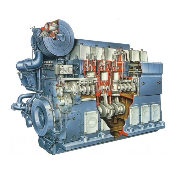
GENERAL Manual F 240 DESCRIPTION OF THE ENGINE DESCRIPTION OF THE ENGINE 1. Crankshaft and The crankshaft is made from a one piece alloy steel forging. The dimensions of the bedplate crankpins are identical throughout the range of engines, as are the dimensions of the main bearing journals in order to optimize standardisation between engine components of different cylinder configurations. -
Page 18: Injection Equipment
GENERAL Manual F 240 DESCRIPTION OF THE ENGINE 7. Injection equip- The injection equipment is made by Bosch. The high pressure fuel pumps are of the ment single--cylinder and flow--through type. The fuel injector is centrally located in the cylin- der head. - Page 19 GENERAL Manual F 240 DESCRIPTION OF THE ENGINE Cross section F240 --o--o--o--o--o-- 1000 F 910 0 - - 7 Ver. 01...
- Page 20 GENERAL Manual F 240 DESCRIPTION OF THE ENGINE 0 - - 8 Ver. 01...
-
Page 21: Chapter 1: Operation
During operation In a diesel engine, the crankshaft and its associated dynamic masses form an elastic system. The vibration of these masses around the centre line of the shafts in the system is called torsional vibration. By the use of a vibration damper these vibrations can usually be kept to an acceptable level. - Page 22 OPERATION Manual F 240 GENERAL Stopping the For stopping the engine see section 9B of the manual. If the engine is to be engine non--operational for more than 8 hours then proceed as follows: 2. 1. If the engine is to remain stopped for more than 24 hours close the main fuel supply valve to the engine in order to prevent leakage.
-
Page 23: Chapter 2: Background Information
Golden rule The satisfactorily operation of a diesel engine depends mainly on the quality of the systems that support the engine. In order to guarantee a trouble free and smooth plant operation one should take into account the following remarks. - Page 24 BACKGROUND INFORMATION Manual F 240 OPERATION AND SUPERVISION 1. 5. Sufficient means and ”tools” have to be available for optimum working capacity of the operator and uninterrupted operation of the engine and installation. 1. 6. Run the engine and installation in a safe way. This can be realised when one keeps the following items in mind: The installation is assembled and in operation according the manufactures prescriptions.
-
Page 25: Removal
BACKGROUND INFORMATION Manual F 240 INSPECTION AND MAINTENANCE INSPECTION AND MAINTENANCE Read the following rules carefully before performing any inspection and/or maintenance work on the engine. 1. 1. Use the Manual during maintenance work together with the Parts 1. General Catalogue. -
Page 26: Mounting
BACKGROUND INFORMATION Manual F 240 INSPECTION AND MAINTENANCE 3. Mounting 3. 1. Make sure that all parts are carefully cleaned (free of carbon deposit) before mounting. Do not use cotton waste for cleaning the inside of the engine but always use lint free cleaning rags. 3. -
Page 27: Crank Degrees Nine Cylinder Engine
BACKGROUND INFORMATION Manual F 240 CRANK DEGREES NINE CYLINDER ENGINE CRANK DEGREES NINE CYLINDER ENGINE 1. General Crank Degrees off the Flywheel on 9F240 Engines : The nine cylinder engines have irregular crank angles, i.e. an irregular number of de- grees between T.D.C.’s on the flywheel. -
Page 28: Engine Tools
BACKGROUND INFORMATION Manual F 240 ENGINE TOOLS ENGINE TOOLS 1. General Engine tools that are necessary for maintenance jobs on the engine are defined in sec- tion ”NECESSARY TOOLS” from chapter 11 onwards. Build--up of this section: -- description of the function and the code number of the complete tool; -- item number of the separate tool with description and in brackets the quantity and code number ;... -
Page 29: Index Of Symbols
BACKGROUND INFORMATION Manual F 240 INDEX OF SYMBOLS INDEX OF SYMBOLS TURBOCHARGER SCHEMATIC BUTTERFLY VALVE 9604SW149 - -o- -o- -o- -o- -o- - 2 - - 7 Ver. 01... - Page 30 BACKGROUND INFORMATION Manual F 240 INDEX OF SYMBOLS 2 - - 8 Ver. 01...
-
Page 31: Chapter 3: Technical Data 3A Main Data
TECHNICAL DATA Manual F 240 MAIN DATA MAIN DATA Engine Type: Four stroke with direct injection specifications Cylinder bore: 240 mm. Stroke: 260 mm. Swept volume: 11,8 l / cyl. Compression ratio: 13 : l. Configuration: 6, 8 en 9 cylinders in line Pressure charging: Turbocharging and air cooler(s). -
Page 32: Combustion Sequence
TECHNICAL DATA Manual F 240 MAIN DATA 7. Cilinder The cylinders are progressively numbered to the flywheel. The cylinder next to the numbers flywheel has the highest number. 6 F 240 8 F 240 9 F 240 Fig. B1 8. Combustion Normal rotation. -
Page 33: Temperatures
TECHNICAL DATA Manual F 240 MAIN DATA 11. Pressures Starting air: 30 bar Lubricating oil on main bearings with normal lub.oil temperature: 3 bar Openings pressure injector : 300 bar 12. Temperatures Lubricating oil before engine 70GC Cooling water after engine : 85GC Max. -
Page 34: Tightening Torques
TECHNICAL DATA Manual F 240 TIGHTENING TORQUES TIGHTENING TORQUES Unless stated otherwise: all threads and contact surfaces of the nuts and bolts should be sparingly lubricated with engine oil, before tightening. Never use other lubricants. Group Description 1. Cylinder step : Tighten all nuts by hand , tighten nut B with 20 Nm and turn back 30 degr. -
Page 35: Camshaft
TECHNICAL DATA Manual F 240 TIGHTENING TORQUES Group Description 4. Camshaft Bolt in support for intermediate gear wheel Bolts for fitting the roll holder 5. Connecting rod Nuts for connecting rod cap step hand tight step step 6. Main bearings Nuts for main bearing caps, phase I : phase II :... -
Page 36: Assembly Tie Rods
TECHNICAL DATA Manual F 240 TIGHTENING TORQUES 9. Assembly To obtain the right pre--tension on the tie rods, they must be connected the following tie rods way: Apply sealing lute between the contact surfaces of cylinder block and crankcase. Place cylinder block on top of the crankcase. Tighten the cylinder block the same day completely on the crankcase, with regard to hardening of the lute. - Page 37 TECHNICAL DATA Manual F 240 TIGHTENING TORQUES Turn nuts “X” according to sequence diagram (fig. B4), with a torque of 275 Nm. Repeat this procedure once more . The nuts “Y” should be blocked now. Fig. Indicate point zero for the angular rotation by means of removable pencil on nut “X”...
-
Page 38: Go Criteria
The given no go criteria and max. allowable clearances are only an indication. The final decision of replacing a part is the responsibility of the Technical Department and also depends on the kind of operation. Stork--Wärtsilä Diesel can therefore take no responsebility for the correctness of this decision. Part... -
Page 39: Camshaft
TECHNICAL DATA Manual F 240 NO GO CRITERIA Part Description No go Max. criteria allowable clearance - - - - - - - - - - - - - - - - - - - - - - - - - - - - - - - - - - - - - - - - - - - - - - - - - - - - - - - - - - - - - - - - - - - - - - - - - - - - - - - - - - - - - - - - - - - - - - - - - - - - - - - - - - - - - - - - - - - - - - - - - - - - - - - - - - - - Camshaft Bore camshaft bearing 0.250... - Page 40 TECHNICAL DATA Manual F 240 NO GO CRITERIA 3 - - 10 Ver. 02...
-
Page 41: General
Section 4B gives a description when and which inspection and maintenance actions have to be carried out. In case you need any further explanation, contact the service department of Stork--Wärtsilä Diesel. With the aid of the test report and earlier observations list it is possible to detect and resolve faults by calculated actions. - Page 42 INSPECTION AND MAINTENANCE Manual F 240 GENERAL 11. Weekly check Check the quality of the engine cooling water weekly and when the water is changed, and/or each time cooling water agents are added. The manufacturers’ specifications and instructions for the relevant products should be followed with regard to the use of additives and tests of the quality of the engine cooling water.
-
Page 43: Observation List
INSPECTION AND MAINTENANCE Manual F 240 GENERAL 12. OBSERVATION DATE ..--..--.. LIST Time Engine speed rpm. Turbocharger speed rpm. Fuel control rod position Load HT cooler LT--cooler Lubricating oil Fuel Receiver pressure Exhaust gases after turboch. m.bar Barometer m.bar Inlet air Air after turbocharger Air after cooler Water before air coolers... -
Page 44: Inspection And Maintenance Procedures
INSPECTION AND MAINTENANCE Manual F 240 INSPECTION AND MAINTENANCE PROCEDURES INSPECTION AND MAINTENANCE PROCEDURES Inspection and maintenance procedures are described in this section. 1. Maintenance The total running hours between the overhauls as well as the effective life of components interval / effective are guide lines and depend on the following aspects: life... -
Page 45: Daily Maintenance
INSPECTION AND MAINTENANCE Manual F 240 INSPECTION AND MAINTENANCE PROCEDURES 3. Daily maintenance 3. 1. Inlet/outlet 8C o Check if both water condensate drains in the air inlet casing are open ; system 8D o Clean the turbocharger on the compressor side by means of water injection. 3. -
Page 46: Weekly Maintenance
INSPECTION AND MAINTENANCE Manual F 240 INSPECTION AND MAINTENANCE PROCEDURES 4. Weekly maintenance 4. 1. Fuel system o Check the governor and fuel rack linkage and keep it running easily. 4. 2. Lubricating oil 6D o Clean the centrifugal by--pass lubricating oil filter and renew the insert filter paper system 6E o Check the working of the inlet valve seat lubrication visually. -
Page 47: Hours Overhaul
INSPECTION AND MAINTENANCE Manual F 240 INSPECTION AND MAINTENANCE PROCEDURES 5. 750- -Hours overhaul 5. 1. Fuel system o Check the governor and fuel rack linkage and keep it running easily. 5. 2. Lubricating oil 6B o Check the quality of the lubricating oil ; system 6D o Clean the centrifugal by--pass lubricating oil filter and renew the insert filter paper ;... -
Page 48: 1500- -Hours Overhaul
INSPECTION AND MAINTENANCE Manual F 240 INSPECTION AND MAINTENANCE PROCEDURES 6. 1,500- -Hours overhaul 6. 1. Cylinder head / 18G o Check the valve clearance and adjust it if necessary. valves 6. 2. Fuel system o Check the governor and fuel rack linkage and keep it running easily ; 5C o Replace the fuel filter elements. -
Page 49: 3000- -Hours Overhaul
INSPECTION AND MAINTENANCE Manual F 240 INSPECTION AND MAINTENANCE PROCEDURES 7. 3,000- -Hours overhaul 7. 1. Cylinder head / 18G o Check the valve clearance and adjust it if necessary. valves 7. 2. Fuel system o Check the governor and fuel rack linkage and keep it running easily ; 5C o Renew the fuel filter elements ;... -
Page 50: 6000- -Hours Overhaul
INSPECTION AND MAINTENANCE Manual F 240 INSPECTION AND MAINTENANCE PROCEDURES 8. 6,000- -Hours overhaul 8. 1. Cylinder head / 15B o Inspect the running surface of the cylinder liners by means of an endoscope; valves / 18 o Inspect all the valves and the valve seats by means of an endoscope ; cylinder liner 18G o Check the valve clearance and adjust it if necessary. - Page 51 INSPECTION AND MAINTENANCE Manual F 240 INSPECTION AND MAINTENANCE PROCEDURES Continued 6,000- -hours 8. 8. Inlet/outlet oHave the turbochargers completely cleaned, inspected and overhauled if system necessary ; o Inspect the air cooler at the air inlet side by means of an endoscope ; SSMo Clean the air inlet filter ;...
-
Page 52: 12000- -Hours Overhaul
INSPECTION AND MAINTENANCE Manual F 240 INSPECTION AND MAINTENANCE PROCEDURES 12,000- -Hours overhaul 9. 1. Cylinder head / 15B o Inspect the running surface of the cylinder liners by means of an endoscope; valves / 18--o Inspect all valves and valve seats by means of an endoscope ; cylinder liner 18--o Remove one cylinder head for visual inspection of the cylinder head, the valves and the valve seats ;... - Page 53 INSPECTION AND MAINTENANCE Manual F 240 INSPECTION AND MAINTENANCE PROCEDURES Continued 12,000- -hours 9. 7. Lubricating oil o Replace the lubricating oil depending of the system contents, or check the quality system of the lubricating oil ; 20C o Clean the inside of the governor and change the lubricating oil ; 22A o Take a sample of the vibration damper fluid and have it examined ;...
- Page 54 INSPECTION AND MAINTENANCE Manual F 240 INSPECTION AND MAINTENANCE PROCEDURES 10. 24,000- -Hours overhaul 10. 1. Cylinder head / 18--o Overhaul the cylinder heads ; valves / o Inspect the contact surfaces of the cylinder liner with the cylinder block and cylinder cylinder liner head ;...
- Page 55 INSPECTION AND MAINTENANCE Manual F 240 INSPECTION AND MAINTENANCE PROCEDURES Continued 24,000- -hours 10. 7. Lubricating oil o Inspect the safety valve and overflow valve ; system o Overhaul the lubricating oil pump(s) ; 6H o Check the wax elements of the thermostatic valve on good working order ; 6D o Clean the centrifugal by--pass oil filter and renew the insert filter paper ;...
- Page 56 INSPECTION AND MAINTENANCE Manual F 240 INSPECTION AND MAINTENANCE PROCEDURES 11. 36,000- -Hours overhaul 11. 1. Cylinder head / 15B o Inspect the running surface of all cylinder liners by means of an endoscope; valves / 18 o Remove one cylinder head for visual inspection + inspect visual the supporting sur- cylinder liner faces of the cylinder liner with the cylinder head, valves and valve seats ;...
- Page 57 INSPECTION AND MAINTENANCE Manual F 240 INSPECTION AND MAINTENANCE PROCEDURES Continued 36,000- -hours 11. 7. Lubricating oil o Replace the lubricating oil depending of the system contents, or check the quality system of the lubricating oil ; 20B o Clean the inside of the governor and change the lubricating oil ; 22A o Take a sample of the vibration damper fluid and have it examined ;...
-
Page 58: Running- -In
INSPECTION AND MAINTENANCE Manual F 240 TEST RUNNING TEST RUNNING 1. Test running After maintenance and/or repair work on engine parts, a test running procedure must be followed. The test running has to be carried out by idling the engine for max. 5 minutes at 30% of the rpm. - Page 59 INSPECTION AND MAINTENANCE Manual F 240 TEST RUNNING Explanation to figure 4.1 and recommended time: -- a = gradual load increase 0,5 hr. minimum ; -- b = 0,75 hr. to 1 hr ; -- c = 0,2 hr. to 0,25 hr ; -- 3, 4 etc.= load step.
-
Page 60: Functional Test
INSPECTION AND MAINTENANCE Manual F 240 TEST RUNNING Graph B Running--in programme for piston rings and cylinder liners. Generator operation: --3.0 --2.0 --1.0 0.0 9.0 10.0 11.0 12.0 13.0 14.0 t [hr.] ________ = Output _ _ _ _ _ = Speed 3. -
Page 61: Chapter 5: Fuel System 5A Introduction
INTRODUCTION INTRODUCTION 4. General Good performance of a diesel engine greatly depends on the correct timing, correct quantity and good atomisation of the fuel injection. 5. Description of This paragraph is a general description of the function of engine parts in the fuel engine parts system. -
Page 62: Fuel Injector (1.5)
FUEL SYSTEM Manual F 240 INTRODUCTION Fuel Injector The main components of the fuel injector are: (1.5) -- nozzle holder ; -- nozzle. The nozzles are of the ”multihole type” and actuated by the fuel pressure. For maintenance, testing and adjusting of the open- ing pressure, see chapter 17. -
Page 63: Fuel Requirements
-- ISO 8217 F--DMX, DMA and DMB ; -- (BSMA 100:1989 class M2). If you want to use a fuel which does not meet the requirements, please consult Stork--Wärtsilä Diesel. Engine fuel All fuel supplied to the engine must be properly cleaned from solid particles and water. -
Page 64: Fuel Filter Element
FUEL SYSTEM Manual F 240 FUEL FILTER ELEMENT FUEL FILTER ELEMENT Before starting work, consult: -- chapter 2, ”BACKGROUND INFORMATION”. 1. General The fuel filter consists of two compartments, each having one filter element. The fuel filter has a 3--way cock permitting change--over during operation and the fouled filter to be renewed. -
Page 65: Fitting
FUEL SYSTEM Manual F 240 FUEL FILTER ELEMENT 3. Fitting 3. 1. Clean the filter compartment and the cover with clean gasoil. 3. 2. Check the O--ring for damage. Replace it, if necessary. 3. 3. Check that the seat edges of the filter compartment and of the filter cover are properly cleaned and undamaged. -
Page 66: Inspections, Moment Of Injection
FUEL SYSTEM Manual F 240 INSPECTIONS, MOMENT OF INJECTION INSPECTIONS, MOMENT OF INJECTION Before starting work, consult: -- chapter 2, ”BACKGROUND INFORMATION”. 1. Training tools The following tools are used during the training course. Tool A Tool to check the beginning of the fuel injection. Capillary tube capillary tube union nut... -
Page 67: Fuel Control System
FUEL SYSTEM Manual F 240 INSPECTIONS, MOMENT OF INJECTION Tool C dummy The ”dummy” consists of a teflon model with the same dimensions as the constant pressure valve, sealed by an O--ring or an old constant pressure valve with the inside valves and springs removed. -
Page 68: Verification Of Moment Of Injection
FUEL SYSTEM Manual F 240 INSPECTIONS, MOMENT OF INJECTION 3. Verification of moment of injection 3. 1. Disconnect the high pressure fuel line. 3. 2. Fit the capillary tube with the union nut. 3. 3. Move the fuel pump control rod to its full load position. -
Page 69: Checking Pre- -Lifting
FUEL SYSTEM Manual F 240 INSPECTIONS, MOMENT OF INJECTION 4. Checking After fitting a new or reconditioned high pressure fuel pump, the pre lifting has to be pre- -lifting checked and/or adjusted. Proceed as follows: 4. 1. Close the fuel supply to the engine. -
Page 70: Constant Pressure Valve
FUEL SYSTEM Manual F 240 CONSTANT PRESSURE VALVE CONSTANT PRESSURE VALVE Before starting word, consult: --chapter 2, ”BACKGROUND INFORMATION”. 1. TOOL Tool for testing constant pressure valve. Tool A Testing pump 9612 SW 416 Tool B Tool 66626 900, consists of: Connecting pieces ;... -
Page 71: General Diagram
FUEL SYSTEM Manual F 240 GENERAL DIAGRAM GENERAL DIAGRAM Explanation of the item numbers in the diagram on the next page. 1. Fuel supply and Name return 1. 1. Engine driven fuel feed pump 1. 2. Duplex fine filter 1. 3. High pressure fuel pump 1. - Page 72 FUEL SYSTEM Manual F 240 GENERAL DIAGRAM --o--o--o--o--o-- 5 - - 12 Ver. 01...
-
Page 73: Lubricating Oil Pump (1.0)
LUBRICATING OIL SYSTEM Manual F 240 INTRODUCTION INTRODUCTION 1. General Lubrication of the engine takes place by means of an engine driven lubricating oil pump. This self--suction pump draws oil, via a coarse filter, from the sump or a separate oil tank. -
Page 74: Chapter 6: Lubricating Oil System 6A Introduction
LUBRICATING OIL SYSTEM Manual F 240 INTRODUCTION Main lubricating oil From the main lubricating oil manifold via lubrication oil pipes oil is supplied to the manifold (1.7) crankshaft and the connecting rods, the main, big end and gudgeon pin bearings. The main lubricating oil also effectets the cooling of the pistons through the main lubricating oil manifold, as well as lubrication of the gears for the camshaft drive and pump housing. -
Page 75: Lubricating Oil Requirements
Since Stork--Wärtsilä Diesel neither manufactures nor supplies oil, Stork Wärtsilä Diesel does not control or know the complete composition of a lubricating oil brand, type or batch and therefore cannot give any guarantee that a lubricating oil brand, type or batch will behave satisfactorily under all operating conditions. -
Page 76: Testing Engine Lubricating Oil
LUBRICATING OIL SYSTEM Manual F 240 LUBRICATING OIL REQUIREMENTS 4. Testing engine When testing the quality of the lubricating oil for the engine the specifications and lubricating oil instructions of the oil supplier have to be observed. Under normal operating conditions samples of lubricating oil should be taken in accordance with the maintenance schedule. -
Page 77: Lubricating Oil Filter
LUBRICATING OIL SYSTEM Manual F 240 LUBRICATING OIL FILTER LUBRICATING OIL FILTER 1. General The lubricating oil is filtered before it enters the engine. The lubricating oil filter has four filter compartments. The filter compartments are connected in pairs. Two of the four compartments are always in use. The magnetic core of the filter, and the element are both attached to the cover, so that these can be withdrawn together. -
Page 78: Assembly
LUBRICATING OIL SYSTEM Manual F 240 LUBRICATING OIL FILTER Open only filter compartments that are not in use! 2. Replacing 2. 1. Clean the upper surface of the filter housing and the filter covers, so that no dirt can fall into the compartments during removal. -
Page 79: Centrifugal Filter
LUBRICATING OIL SYSTEM Manual F 240 CENTRIFUGAL FILTER CENTRIFUGAL FILTER 1. General The use of the centrifugal filter increases the lifetime of the filter elements. The working of the filter is based on centrifugal force. The engine lubricating oil is pumped into the filter through passage “x”... - Page 80 LUBRICATING OIL SYSTEM Manual F 240 CENTRIFUGAL FILTER 3. 5. Check whether the O--rings are damaged; if so, renew them. 3. 6. Insert new filter paper into the rotor cover. 3. 7. Assemble the rotor together and turn nut C hand tight. Turn nut C 180 futher.
-
Page 81: Lubrication Of Inlet Valve Seats
LUBRICATING OIL SYSTEM Manual F 240 LUBRICATION OF INLET VALVE SEATS LUBRICATION OF INLET VALVE SEATS 1. General To minimize wear of inlet valves and inlet valve seats some oil is automatically supplied to the air inlet duct just before the inlet valves. The oil is atomized by the charge air, passing with high speed through the air inlet duct. -
Page 82: Barrier Oil System High Pressure Fuel Pumps
LUBRICATING OIL SYSTEM Manual F 240 BARRIER OIL SYSTEM HIGH PRESSURE FUEL PUMPS BARRIER OIL SYSTEM HP FUEL PUMPS 1. General The barrier oil system for the HP fuel pumps (if applicable) forms part of the main oil lubrication system. In order to prevent fuel leaking along the plungers into the camshaft housing, a groove around the plunger piston is filled with lubricating oil under pressure. -
Page 83: Inspections
LUBRICATING OIL SYSTEM Manual F 240 INSPECTIONS INSPECTIONS 1. Lubricating Oil The lubricating oil system includes two overflow valves, namely : Overflow Valves Safety overflow valve (before lubricating oil filter, setting + 5 bar) Pressure regulating valve (after the lubricating oil filter, setting +3 bar) Working Principle One side of the overflow valve is exposed to the lubricating oil pressure, while a spring force acts on the other. -
Page 84: Lubricating Oil Thermostats
LUBRICATING OIL SYSTEM Manual F 240 LUBRICATING OIL THERMOSTATS LUBRICATING OIL THERMOSTATS 1. General The thermostat three--way valve is equipped with two elements. In a cold condition, the thermostatic elements are closed and hardly no oil flows through the heat exchanger. -
Page 85: General Diagram
LUBRICATING OIL SYSTEM Manual F 240 GENERAL DIAGRAM GENERAL DIAGRAM Explanation of the item numbers in the diagram. 1. Main lubricating Name oil flow 1. 0. Engine driven lubricating oil pump 1. 1. Non return valve 1. 2. Thermostatic three--way valve 1. - Page 86 LUBRICATING OIL SYSTEM Manual F 240 GENERAL DIAGRAM 6. General Diagram --o--o--o--o--o-- 6 - - 14 Ver. 01...
-
Page 87: Chapter 7: Cooling Water System
COOLING WATER SYSTEM Manual F 240 INTRODUCTION INTRODUCTION 7. General During the combustion process in the engine, heat is transfered to various engine parts. To protect these parts against overly high temperatures it is necessary to dissipate the heat by means of cooling water systems. This paragraph is a general description of the function of engine parts in the cooling water system. -
Page 88: Description Engine Parts Lt- -Circuit
COOLING WATER SYSTEM Manual F 240 INTRODUCTION 9. Describtion The LT--circuit includes the charge air cooler, or if fitted, only the second stage of a two engine parts stage air cooler, the lubricating oil cooler and optionally heat exchangers. LT- -circuit Cooling water The cooling water pump for the LT--circuit is of the same construction as the cooling pump... -
Page 89: Requirements
1. 4. The cooling water must be treated with a cooling water inhibitor (on an ni- trite--borate basis): Tap water is usually not suitable for use in diesel engines. Cooling water treatment is absolutely necessary in order to protect the engine against deposits, pollution, corrosion, cavitation and the growth of bacteria in the cooling water system. - Page 90 COOLING WATER SYSTEM Manual F 240 REQUIREMENTS 2. Cooling water Recommended suppliers of cooling water treatments with addresses of respectively treatments the head office and the branch office in the Netherlands are: Product Head Office Office in the Netherlands 2. 1. Cooltreat 101: Houseman &...
-
Page 91: Checking Of Cooling Water Quality
Check in accordance with the recommendations and instructions of the supplier of the product. Check: -- Nitrite content (ph--value) -- Chloride content Note: Stork--Wärtsilä Diesel b.v. does not accept any responsibility for the specific applica- tion of cooling water treatments. --o--o--o--o--o-- 7 - - 5 Ver. 01... -
Page 92: Cooling Water De- -Aeration
COOLING WATER SYSTEM Manual F 240 COOLING WATER DE- -AERATION Before starting work, consult: -- chapter 2, ”BACKGROUND INFORMATION”. General Cooling water de--aeration on the engine takes place via the highest points of the cooling water system. Orifices are provided in the de--aeration connections. These orifices must be checked periodically. -
Page 93: Coolers
COOLING WATER SYSTEM Manual F 240 COOLERS Before starting work, consult -- chapter 2, ”BACKGROUND INFORMATION”. 1. The heat Cleaning and Inspection of lube oil or water cooler: Exchangers Cleaning Intervals depend heavily on the operating conditions and the state of the cooling water. -
Page 94: Cooling Water Thermostats
COOLING WATER SYSTEM Manual F 240 COOLING WATER THERMOSTATS Before starting work, consult: -- chapter 2, ”BACKGROUND INFORMATION”. The thermostatic three--way valve is equipped with three elements. In cold condition, the thermostatic elements are closed and no water can flow through the heat exchanger. When the temperature of the water rises, the wax elements expand, and causes the elements to open against spring pressure, so that the passage to the heat exchanger is released. -
Page 95: Cooling Water Pump
COOLING WATER SYSTEM Manual F 240 COOLING WATER PUMP 1. Disassembly If oil and / or water is seen to run out of the leak indicator F, all sealing rings have to be renewed. 1. 1. Remove the suction and delivery pipe from the pump. 1. - Page 96 COOLING WATER SYSTEM Manual F 240 COOLING WATER PUMP 2. Reassembly Fitting a new inner ring should be done as follows: 2. 1. Clean and degrease the pump shaft on the location, for the inner ring. 2. 2. Degrease the new inner ring. 2.
-
Page 97: Inspection Cooling Water Space
COOLING WATER SYSTEM Manual F 240 INSPECTION COOLING WATER SPACE This consists of a general visual examination of the cylinder block cooling water space. Attention should be paid to the following : Serious corrosion ; Signs of cavitation ; Sludge formation ; Line deposits and other undesirable phenomena ;... -
Page 98: General Diagram
COOLING WATER SYSTEM Manual F 240 GENERAL DIAGRAM Explanation of the item numbers in the diagram. 1. HT- -circuit Name 1. 0 Cooling water pump ; 1. 1. Cooling water inlet channel ; 1. 2. Cooling water outlet manifold ; 1. - Page 99 COOLING WATER SYSTEM Manual F 240 GENERAL DIAGRAM --o--o--o--o--o-- 7 - - 13 Ver. 01...
- Page 100 COOLING WATER SYSTEM Manual F 240 GENERAL DIAGRAM 7 - - 14 Ver. 01...
-
Page 101: Chapter 8: Air Inlet And Exhaust System
AIR INLET AND EXHAUST SYSTEM Manual F 240 INTRODUCTION INTRODUCTION 5. General In order to optimize the engine’s performance, it is necessary to compress and to regulate the temperature of the combustion air. This is carried out by the use of a turbocharger and an air cooler 6. -
Page 102: Air Cooler (1.4)
AIR INLET AND EXHAUST SYSTEM Manual F 240 INTRODUCTION Air cooler The combustion air passes the turbocharger and flows into the air cooler. The air (1.4) cooler cools the combustion air to receiver temperature. In the air cooler there is a slight pressure drop. After the air cooler the combustion air flows via the air receiver into the cylinders. -
Page 103: Combustion Air Requirements
AIR INLET AND EXHAUST SYSTEM Manual F 240 COMBUSTION AIR REQUIREMENTS COMBUSTION AIR REQUIREMENTS 1. Specification The combustion air must meet the following requirements: -- it must be sufficient free of: -- dust ; -- fluid ; -- chemical pollution. -- maximum resistance of the inlet system before the turbocharger(s) 20 mbar ;... -
Page 104: Charge Air Condensation
AIR INLET AND EXHAUST SYSTEM Manual F 240 CHARGE AIR CONDENSATION Before starting work, consult: -- chapter 2, ”BACKGROUND INFORMATION”. Condensate is developed by cooling down of warm inlet air. The condensate is constantly drained via two small discharges at the lowest points of the air inlet housing. -
Page 105: Turbocharger
AIR INLET AND EXHAUST SYSTEM Manual F 240 TURBOCHARGER Before starting work, please consult: -- chapter 2, ”BACKGROUND INFORMATION” ; -- part 3, ”SUB SUPPLIERS MANUALS”. 1. General Even the slightest fouling can cause a rise in temperature of the charge air and/or drop of the charge air pressure after the compressor. -
Page 106: Cleaning Of The Air Filter
AIR INLET AND EXHAUST SYSTEM Manual F 240 TURBOCHARGER 3. Cleaning the air The filter must be cleaned from time to time. The frequence with which this must be filter done depends on the dust content of the suction air and the number of running hours of the engine. -
Page 107: Exhaust Compensators
AIR INLET AND EXHAUST SYSTEM Manual F 240 EXHAUST COMPENSATORS Before starting work, please consult: -- chapter 2, ”BACKGROUND INFORMATION”. 1. Necessary Tool A. tools Dummy for the compensator. When replacing a compensator, a dummy is used for aligning the exhaust pipe flanges. Tool number 6104 F 457: 66562--001 Tool number 6104 F 459: 66562--004 2. -
Page 108: General Diagram
AIR INLET AND EXHAUST SYSTEM Manual F 240 GENERAL DIAGRAM Explanation of the item numbers in the diagram. 1. Air inlet Name 1. 1. Inlet air filter ; 1. 2. Turbocharger, (1.2.1 = Compressor and 1.2.2 = Turbine) ; 1. 3. Expansion compensator 1. -
Page 109: Chapter 9: Starting And Stopping System
The compressed air is only used for the above mentioned engine procedures and (1.--) should be free of water. In case the compressor forms part of the Stork--Wärtsilä Diesel supply, consult the Sub--suppliers manuals for details. The starting air is supplied via a starting air valve (1.3), to be operated manually or/and electrically, as starting air to the starting air valves (1.5), and as pilot air to the air... -
Page 110: Starting Procedure
STARTING AND STOPPING SYSTEM Manual F 240 STARTING PROCEDURE STARTING PROCEDURE 1. Prior to Starting Prior to starting the following preparations have to be made: Fuel system o Check the fuel level of the day tank. Fill up if necessary ; o Check if the valves are in the correct position. -
Page 111: Starting Air Distributor
STARTING AND STOPPING SYSTEM Manual F 240 STARTING AIR DISTRIBUTOR STARTING AIR DISTRIBUTOR Before starting work please, consult: -- chapter 2, ” BACKGROUND INFORMATION”. The air distributor disc takes care that pilot air flows to the starting valve of the cylinder just starting its firing stroke. -
Page 112: Setting The Distributor Disc
STARTING AND STOPPING SYSTEM Manual F 240 STARTING AIR DISTRIBUTOR 2. 1. Fit the cover, using a new gasket. 2. 2. Connect the air supply line to the cover of the starting air distributor. 3. Setting the distributor disc 3. 1. Turn the flywheel to 5G past the top dead centre of e.g. cylinder 1. 3. -
Page 113: General Diagram
STARTING AND STOPPING SYSTEM Manual F 240 GENERAL DIAGRAM GENERAL DIAGRAM Explanation of the numbers in the diagram, of a 6 cylinder clockwise turning engine for operation on MDO. The pipelines between the engine parts 1.2 to 1.5 are for starting air, the other pipelines are for pilot air. - Page 114 STARTING AND STOPPING SYSTEM Manual F 240 GENERAL DIAGRAM 9 - - 6 Ver. 01...
-
Page 115: Chapter 10: Alarm And Safety System
ALARM AND SAFETY SYSTEM Manual F 240 DESCRIPTIONS DESCRIPTIONS 5. General The engine is provided with equipment for protection against several kinds of faults. The engine protection system is divided into: -- speed transmitter ; -- alarm and protection switches ; -- alarm and protection unit optional delivery ;... - Page 116 Note ! The adjustments of the converter card and the overspeed card are calibrated by Stork--Wärtsilä Diesel with special equipment. Since the complete protection of the engine depends on this adjustment, other people are not allowed to change these adjustments. This is also the case for the cards (E4) and (E5).
-
Page 117: Alarm And Protection Switches
ALARM AND SAFETY SYSTEM Manual F 240 DESCRIPTIONS 6. 7. Wire break monitoring card for the stopping device (E6): This provision is only supplied when it is specially required by the applicable classification society, and must be seen as an optional extra. In order to monitor wire breaks in the shutdown system, a special card is built in. -
Page 118: Alarm And Protection Unit
ALARM AND SAFETY SYSTEM Manual F 240 DESCRIPTIONS 8. Alarm and The alarm and protection units display the alarm and protection signals of the engine. protection unit See section 10D for the diagram, in the standard design, comprising of the following components: 8. -
Page 119: Co- -Signaling Board
ALARM AND SAFETY SYSTEM Manual F 240 DESCRIPTIONS 8. 3. Alarm cards (1.3): Signal indicators, for alarm only, are equipped with illuminated push buttons with orange lenses. The signal indicators, which also have a shut--down function, and the illuminated push buttons are provided with red lenses. By means of the push button element of the illuminated push button, each alarm and protection function can be tested separately. -
Page 120: Testing The Settings
ALARM AND SAFETY SYSTEM Manual F 240 TESTING THE SETTINGS TESTING THE SETTINGS 1. General The settings of the alarm and trip switches on the engine and of the printed circuit boards in the electronic speed transmitter are given in the test report and the electrical drawings delivered with the engines. - Page 121 ALARM AND SAFETY SYSTEM Manual F 240 TESTING THE SETTINGS 2. 5. Checking the operation of cards, alarm, delay and stop functions: All alarm and trip switches should be checked by hand operation when the engine is running. If the switches operate correctly the corresponding signal will appear on the alarm and safety system and the engine will be tripped if applicable.
- Page 122 6. 1. Alarm signal wire break stopping air solenoid valve. Rpm indicator ; Reset button ; Running hours counter. Key to letters Description Camshaft gear wheel ; Impulse pick--up ; Stopping air solenoid valve ; External stopping signals. No standard delivery Stork--Wärtsilä Diesel. 10 - - 8 Ver. 01...
-
Page 123: Diagram Rpm Measuring System
ALARM AND SAFETY SYSTEM Manual F 240 DIAGRAM RPM MEASURING SYSTEM Schematic diagram --o--o--o--o--o-- 10 - - 9 Ver. 01... -
Page 124: Diagram Alarm And Safety
ALARM AND SAFETY SYSTEM Manual F 240 DIAGRAM ALARM AND SAFETY DIAGRAM ALARM AND SAFETY Explanation of components in the schematic diagram ALARM AND SAFETY SYSTEM and Co--signaling tableau, (see next page). 1. Alarm and safety Description system 1. 1. Mains supply printed circuit: 1.1.1 Supply voltage ;... - Page 125 ALARM AND SAFETY SYSTEM Manual F 240 DIAGRAM ALARM AND SAFETY Schematic diagram 1.3.3 2.1.1 1.3.2 1.2.2 1.2.1 1.1.3 1.1.1 1.1.7 1.1.5 1.1.2 1.1.4 1.1.6 --o--o--o--o--o-- 10 - - 11 Ver. 01...
- Page 126 ALARM AND SAFETY SYSTEM Manual F 240 DIAGRAM ALARM AND SAFETY 10 - - 12 Ver. 01...
-
Page 127: Chapter 11: Main Bearings
MAIN BEARINGS Manual F 240 NECESSARY TOOLS NECESSARY TOOLS 9612 F 911 A Tool for removal / fitting the main bearing nuts. Tool A ------------------------------------------------------------------------------------------------------------------------------------ Item No. Description Tool No. ------------------------------------------------------------------------------------------------------------------------------------ BOOMERANG SPANNER 9612 F 010 On the spanner a formula has either been punched in or stuck on. In this formula, L is the length of the torque spanner from the centre of the handgrip to the centre of the pivot on the spanner extension. - Page 128 MAIN BEARINGS Manual F 240 NECESSARY TOOLS Tool B 9612 F 008 Driver. Used to drive the lower bearing shell from under the crankshaft. 11 - - 2 Ver. 01...
- Page 129 MAIN BEARINGS Manual F 240 NECESSARY TOOLS Tool C 9612 F 200 Jig (C1) for locating main bearing bottom shell. 9612F201 Jig (C2) for locating axial main bearing bottom shell. --o--o--o--o--o-- 11 - - 3 Ver. 01...
- Page 130 MAIN BEARINGS Manual F 240 REMOVAL REMOVAL Before starting work, please consult: -- chapter 2 -- BACKGROUND INFORMATION ; -- chapter 3 -- TECHNICAL DATA. 1. Remove crank case covers on both sides of the bearing. 2. Disconnect the lube oil supply pipe to the main bearing cap. 3.
-
Page 131: Replacement
MAIN BEARINGS Manual F 240 REPLACEMENT Before starting work, please consult: -- chapter 2 -- BACKGROUND INFORMATION ; -- chapter 3 -- TECHNICAL DATA. 1. Carefully clean and dry the bearing saddle, the bearing cap, the bearing shells and crankshaft with a lint free cotton cloth. 2. - Page 132 MAIN BEARINGS Manual F 240 REPLACEMENT 6. Connect the lube oil supply pipe to the main bearing cap, Use a new gasket and locking plate. 7. Remove any object from the engine crankcase. 8. Pre--lubricate the engine and check if the bearing is getting oil. 9.
-
Page 133: Chapter 13: Cylinder Block 13A Internal Inspection
CYLINDER BLOCK Manual F 240 INTERNAL INSPECTION Before starting work, please consult: -- chapter 2, ”BACKGROUND INFORMATION”. 11. Crankshaft space For safety reasons, before removing all crankcase covers: close starting air supply to the engine ; open decompression cocks; Attention must be paid to the following : the axial movement of the big end of the connecting rod on the crank pin journal carbon build-up under or near the cylinder liners ;... - Page 134 CYLINDER BLOCK Manual F 240 INTERNAL INSPECTION 13 - - 2 Ver. 01...
-
Page 135: Checking
EXPLOSION VALVE Manual F 240 CHECKING CHECKING Before starting work, please consult: -- chapter 2, ”BACKGROUND INFORMATION”. 13. Remove the crankcase cover complete with explosion valve. 14. Put the crankcase cover with the housing of the explosion valve downwards. 15. Push with a force between 25 and 30 kgs on the valve (A). The valve should now open. - Page 136 EXPLOSION VALVE Manual F 240 CHECKING 14 - - 2 Ver. 01...
-
Page 137: Chapter 15: Cylinder Liner 15A Necessary Tools
CYLINDER LINER Manual F 240 NECESSARY TOOLS NECESSARY TOOLS Tool A Threaded rod. This runs along the length of the liner, and connects the top and bottom flanges. Tool number : 9612F145. Eye nut. This screws on to the top of the threaded rod, and is then attached to the hoist. -
Page 138: Inspection
Therefore, it is recommended to have endoscope inspections carried out by service engineers of Stork Wärtsilä Diesel. The cylinder liner can be inspecteded visually without removing the cylinderhead,by using an endoscope. -
Page 139: Removal
CYLINDER LINER Manual F 240 REMOVAL Before starting work, please consult: -- chapter 2, ”BACKGROUND INFORMATION” ; -- chapter 3, ”TECHNICAL DATA”. bridge 1. Remove the cylinder head. See section piece 18B. 2. Remove the piston and connecting rod assembly. See section 16E. Tool A 3. -
Page 140: Fitting
CYLINDER LINER Manual F 240 FITTING FITTING Before starting work, please consult: -- chapter 2, ”BACKGROUND INFORMATION” ; -- chapter 3, ”TECHNICAL DATA”. 1. When fitting a new or honed cylinder liner, the piston rings must be renewed. Proceed as follows. 2. -
Page 141: Chapter 16: Piston And Connecting Rod
The steel top part of the piston may not be removed other than in consultation with the Service Department of Stork--Wärtsilä Diesel. This means that piston heads must on no account be removed when a routine maintenance job is being effected. -
Page 142: Necessary Tools
PISTON AND CONNECTING ROD Manual F 240 NECESSARY TOOLS NECESSARY TOOLS 9612 F 920 A Set of tools for removal / fitting the piston with Tool A connecting rod. ------------------------------------------------------------------------------------------------------------------------------------ Item No. Description Tool No. ------------------------------------------------------------------------------------------------------------------------------------ CLAMPING RING 9612 F 007 HOISTING RING 9612 F 015 HOLDER... -
Page 143: Item 7
PISTON AND CONNECTING ROD Manual F 240 NECESSARY TOOLS Item 2 HOISTING RING. This ring clamps around the top of the piston, and thereby enables it to be hoisted. Item 3 HOLDER. This tool fits under the connecting rod, and is used, on the end of the lever, to push the piston and connecting rod out of the liner. - Page 144 PISTON AND CONNECTING ROD Manual F 240 NECESSARY TOOLS Item 6 SUPPORTING STRIP. This strip gets bolted across the crank case opening and acts as a pivot for the lever used to force the piston out of the liner. Item 7 BOLT (2x).
-
Page 145: Tool B
PISTON AND CONNECTING ROD Manual F 240 NECESSARY TOOLS 9612 F 910 A Tool for removal the connecting rod cap and the crankpin Tool B bearing shell. ------------------------------------------------------------------------------------------------------------------------------------ Item No. Description Tool No. ------------------------------------------------------------------------------------------------------------------------------------ PISTON SUPPORT 9612 F 009 JACK BOLT 9612 F 017 Item 1 PISTON SUPPORT. - Page 146 PISTON AND CONNECTING ROD Manual F 240 NECESSARY TOOLS 66333- -900 Piston ring pliers Tool C For removal / fitting of piston rings without damage or deformation. --o--o--o--o--o-- 16 - - 6 Ver. 01...
-
Page 147: Removal Big End Bearing
PISTON AND CONNECTING ROD Manual F 240 REMOVAL BIG END BEARING REMOVAL BIG END BEARING Before starting work, please consult: -- chapter 2, ”BACKGROUND INFORMATION”. If only the big end bearings have to be inspected or replaced, it is not necessary to remove the piston and connecting rod. - Page 148 PISTON AND CONNECTING ROD Manual F 240 REMOVAL BIG END BEARING 3. 4. Pull the holding plugs out of the connecting rod foot bolt holes, and remove the crank pin upper bearing shell. 4. Mark the bearing shells halves of each cylinder with e.g. a felt--pen, because when the used shells have to be re--used, it has to be done in exactly the same position and in the same place.
-
Page 149: Fitting Big End Bearing
PISTON AND CONNECTING ROD Manual F 240 FITTING BIG END BEARING FITTING BIG END BEARING Before starting work, please consult: -- chapter 2, ”BACKGROUND INFORMATION” ; -- chapter 3, ”TECHNICAL DATA” . 1. Pay attention to the following points during the fitting procedure: 1. - Page 150 PISTON AND CONNECTING ROD Manual F 240 FITTING BIG END BEARING 4. 5. Fit the connecting rod bolts with new locking plates. 4. 6. Screw the connecting rod nuts hand--tight, diagonally, after lubricating the thread flanks and the contact faces sparingly with clean lubrication oil. 4.
-
Page 151: Removing
PISTON AND CONNECTING ROD Manual F 240 REMOVING REMOVING Before starting work, please consult: -- chapter 2, ”BACKGROUND INFORMATION” ; -- chapter 3, ”TECHNICAL DATA”. If only the big end bearings have to be inspected or replaced, it is not necessary to remove the piston and connecting rod. -
Page 152: Removal Of Gudgeon Pin
PISTON AND CONNECTING ROD Manual F 240 REMOVAL OF GUDGEON PIN REMOVAL OF GUDGEON PIN Before starting work, please consult: -- chapter 2, ”BACKGROUND INFORMATION”. 1. Remove piston and connecting rod. See chapter 16D. 2. Place the piston and connecting rod on a wooden block. 3. -
Page 153: Fitting Of Gudgeon Pin
PISTON AND CONNECTING ROD Manual F 240 FITTING OF GUDGEON PIN FITTING OF GUDGEON PIN Before starting work, please consult: -- chapter 2, ”BACKGROUND INFORMATION”. 1. Clean all parts carefully prior to fitting. Take care not to damage the aluminium piston skirt! Never use emery cloth. -
Page 154: Removal Of Piston Rings
PISTON AND CONNECTING ROD Manual F 240 REMOVAL OF PISTON RINGS REMOVAL OF PISTON RINGS Before starting work, please consult: -- chapter 2, ”BACKGROUND INFORMATION” ; -- chapter 3, ”TECHNICAL DATA” . Tool C 1. Removing piston rings: 1. 1. Release the spring tension of supporting plate B by means of lever A. Push supporting plate B against the inner rim of the piston ring pliers by hand. -
Page 155: Fitting Of Piston Rings
PISTON AND CONNECTING ROD Manual F 240 FITTING OF PISTON RINGS FITTING OF PISTON RINGS Before starting work, please consult: -- chapter 2, ”BACKGROUND INFORMATION” ; -- chapter 3, ”TECHNICAL DATA” . 1. Attention! -- When renewing the piston rings the cylinder liner has to be honed. -- Fit the piston rings in the correct order (see spare parts manual). -
Page 156: Fitting Piston And Connecting Rod
PISTON AND CONNECTING ROD Manual F 240 16K FITTING PISTON AND CONNECTING ROD 16K FITTING PISTON AND CONNECTING ROD Before starting work, please consult: -- chapter 2, ”BACKGROUND INFORMATION” ; -- chapter 3, ”TECHNICAL DATA”. 1. Clean all parts thoroughly. Whilst cleaning the piston, do not use sharp or hard tools. -
Page 157: Tool A
PISTON AND CONNECTING ROD Manual F 240 16K FITTING PISTON AND CONNECTING ROD Tool A 3. Fitting the connecting rod: 3. 1. Fit the support strip B, to the cylinder block using the bolts. 3. 2. Lower the piston and connecting rod until the hoisting ring comes to rest on the piston ring strap clamp. - Page 158 PISTON AND CONNECTING ROD Manual F 240 16K FITTING PISTON AND CONNECTING ROD 16 - - 18 Ver. 01...
- Page 159 FUEL INJECTOR Manual F 240 NECESSARY TOOLS NECESSARY TOOLS Tool A Removing of the fuel injector Tool Nr 9612 F 916 ------------------------------------------------------------------------------------------------------------------------------------ Item No. Description Tool No. ------------------------------------------------------------------------------------------------------------------------------------ PIPE 9612 F 161 RING 9612 F 162 BOLT 9612 F 163 PRESSURE BEARING 9612 F 212 9612 F 169...
- Page 160 FUEL INJECTOR Manual F 240 NECESSARY TOOLS 9612 F 013 Spanner for nozzle holder bush. Tool B Tool code : 17 - - 2 Ver. 01...
- Page 161 FUEL INJECTOR Manual F 240 NECESSARY TOOLS Tool C 9612F908A Test pump used to test fuel injectors. ------------------------------------------------------------------------------------------------------------------------------------ Item No. Description Tool No. ------------------------------------------------------------------------------------------------------------------------------------ Test pump 9612 F 139 Fuel delivery pipe 9612 F 140 17 - - 3 Ver. 01...
- Page 162 FUEL INJECTOR Manual F 240 NECESSARY TOOLS Tool D Special socket for tightening of the nozzle holder nut. Tool code : 66542--0011 17 - - 4 Ver. 01...
-
Page 163: Tool E
FUEL INJECTOR Manual F 240 NECESSARY TOOLS Tool E Boring tool for the removal of jammed sealing rings from under fuel injectors. Tool number: 9612 F 014 --o--o--o--o--o-- 17 - - 5 Ver. 01... -
Page 164: Removal
FUEL INJECTOR Manual F 240 REMOVAL REMOVAL Before starting work, please consult: -- chapter 2, ” BACKGROUND INFORMATION” ; -- chapter 3, ”TECHNICAL DATA”. Fuel Injector The fuel injector consists of: Nozzle Sleeve nut Wearing plate Nozzle holder Pressure rod Joint washer (steel) Pressure spring Spring holder... - Page 165 FUEL INJECTOR Manual F 240 REMOVAL 8. 3. Never try to lever the nozzle holder assembly loose with the aid of the high pressure fuel line, as this may result in the nozzle holder bush rotating slightly, so that it loses the correct tightening torque. This will increase the risk of cooling water leakage into the combustion chamber.
-
Page 166: Checking
FUEL INJECTOR Manual F 240 CHECKING CHECKING Before starting work, please consult: -- chapter 2, ” BACKGROUND INFORMATION” ; -- chapter 3, ”TECHNICAL DATA” 1. Connecting Connecting the nozzle to the test pump (Tool C): 1. 1. Clean the fuel injector externally with pure gasoil. If the fuel injector is out of use only during a very short time, gasoil can be used tor testing. - Page 167 FUEL INJECTOR Manual F 240 CHECKING 5. Test results If deviations were found in tests 2 to 4 the nozzle must be cleaned internally and test repeated. For disassembly see section 17D. For assembly see section 17E. If there are still any deviations, renew the nozzle. --o--o--o--o--o-- 17 - - 9 Ver.
-
Page 168: Disassembly And Testing Of Nozzle
FUEL INJECTOR Manual F 240 DISASSEMBLY AND TESTING OF NOZZLE DISASSEMBLY AND TESTING OF NOZZLE Before starting work, please consult: -- chapter 2, ”BACKGROUND INFORMATION” ; -- chapter 3, ”TECHNICAL DATA”. 1. Disassembly 1. 1. Clean the nozzle holder externally using clean gasoil. 1. -
Page 169: Assembly Of Nozzle
FUEL INJECTOR Manual F 240 ASSEMBLY OF NOZZLE ASSEMBLY OF NOZZLE Before starting work, please consult: -- chapter 2, ”BACKGROUND INFORMATION” ; -- chapter 3, ”TECHNICAL DATA”. 1. Clean the various components of the fuel injector with clean gas oil. If new nozzles have been delivered, flush them through with clean gas oil. -
Page 170: Setting Opening Pressure
FUEL INJECTOR Manual F 240 SETTING OPENING PRESSURE SETTING OPENING PRESSURE Before starting work, please consult: -- chapter 2, ”BACKGROUND INFORMATION” ; -- chapter 3, ”TECHNICAL DATA” . For the required opening pressure, see chapter 3 Technical Data. The proper opening pressure can be brought gradually up by means of the set screw (10), while working the test pump... -
Page 171: Refitting
FUEL INJECTOR Manual F 240 REFITTING REFITTING Before starting work, please consult: -- chapter 2, ”BACKGROUND INFORMATION” ; -- chapter 3, ”TECHNICAL DATA”. If the copper ring in the nozzle holder sleeve is jammed, it can be removed with a boring tool, tool E. - Page 172 FUEL INJECTOR Manual F 240 REFITTING 17 - - 14 Ver. 01...
-
Page 173: Chapter 18: Cylinder Head 18A Necessary Tools
CYLINDER HEAD Manual F 240 NECESSARY TOOLS NECESSARY TOOLS Tool A Socket spanner for cylinder head. Around the base of this socket, angles have been marked to indicate the angular displacement of the cylinder head nuts. Tool number : 9612F235 18 - - 1 Ver. - Page 174 CYLINDER HEAD Manual F 240 NECESSARY TOOLS Tool B Tools assembly/disassembly valve spring and/or valve. Tool number : 9612 F 930. Holding fixture, item 1. This is the fixture which bolts down over the injector clamp stud, and is both used for the lifting of the cylinder head from the cylinder liner, and in order to press down on the pressure pad.
- Page 175 CYLINDER HEAD Manual F 240 NECESSARY TOOLS Tool C T--Wrench -- for undoing the indicator cocks on the cylinder heads. Tool number : 7024 . 612 --o--o--o--o--o-- 18 - - 3 Ver. 01...
-
Page 176: Tool A
CYLINDER HEAD Manual F 240 REMOVAL REMOVAL Before starting work, please consult: -- chapter 2, ”BACKGROUND INFORMATION” ; -- chapter 3, ”TECHNICAL DATA”. 1. Drain the cooling water by removing the plug located in the cylinder block behind the H.T. cooling water pump. The cooling water should be preferably be stored for re--use. -
Page 177: Fitting
CYLINDER HEAD Manual F 240 FITTING Before starting work, please consult: -- chapter 2, ”BACKGROUND INFORMATION” ; -- chapter 3, ”TECHNICAL DATA”. 1. Clean the sealing faces of the cylinder head and cylinder liner very thoroughly. If necessary grind faces using a grinding ring. 2. -
Page 178: Valves
CYLINDER HEAD Manual F 240 VALVES VALVES Before starting work, please consult: -- chapter 2, ”BACKGROUND INFORMATION” ; -- chapter 3, ”TECHNICAL DATA”. 1. Removal 1. 1. Remove cylinder head -- see section 18B. 1. 2. Remove valve springs -- see section 18E. 1. -
Page 179: Valve Springs
CYLINDER HEAD Manual F 240 VALVE SPRINGS VALVE SPRINGS Before starting work, please consult: -- chapter 2, ”BACKGROUND INFORMATION” ; -- chapter 3, ”TECHNICAL DATA”. 1. 1. When only the valve springs need to be inspected or renewed, removal of the 1. - Page 180 CYLINDER HEAD Manual F 240 VALVE SPRINGS 3. Fittting 3. 1. Clean all parts thoroughly. 3. 2. Refit parts in the reverse order after inspection and/or renewal of the valve spring. Note : On inlet valves it is impossible to slip the spring cup over the spring clip. In this case the valve spring must be positioned before the spring clip can be slide around the stem and into its groove.
-
Page 181: Adjustment Of Valve Clearance
CYLINDER HEAD Manual F 240 ADJUSTMENT OF VALVE CLEARANCE ADJUSTMENT OF VALVE CLEARANCE 1. General Proper adjustment of the valve clearance will prolong the life of the valves and the valve seats. A correct valve clearance gives the various components of the valve lift mechanism sufficient space to expand with increasing material temperatures. - Page 182 CYLINDER HEAD Manual F 240 ADJUSTMENT OF VALVE CLEARANCE 2. 6. Loosen locking nut (B) of the adjustable pivot in the bridge piece and block the bridge piece using a spanner. This to prevent the bridge piece guide from being damaged. 2.
-
Page 183: Cylinder Head Safety Valve
CYLINDER HEAD Manual F 240 CYLINDER HEAD SAFETY VALVE Before starting work, please consult: -- chapter 2, ”BACKGROUND INFORMATION” ; -- chapter 3, ”TECHNICAL DATA”. 1. Inspection 1. 1. Remove the cylinder head safety valve from the connecting piece. 1. 2. Remove the connecting piece after screwing the cap or, if available, the indicator cock from the reducing nipple. -
Page 184: Starting Air Valve
CYLINDER HEAD Manual F 240 STARTING AIR VALVE STARTING AIR VALVE Before starting work, please consult: -- chapter 2, ”BACKGROUND INFORMATION” ; -- chapter 3, ”TECHNICAL DATA”. Before removing the starting air valve, the cylinder head has to be removed., see chapter 18B. 1. -
Page 185: Chapter 19: Camshaft
CAMSHAFT Manual F 240 CHECKING VALVE TIMING CHECKING VALVE TIMING Before starting work, please consult: -- chapter 2, ”BACKGROUND INFORMATION” ; -- chapter 3, ”TECHNICAL DATA”. The inlet and exhaust valve timing can to be checked for instance after positioning the camshaft. -
Page 186: Inlet Valve
Top Dead Centre, permitted tolerance is 1 7. If the setting is not correct please consult the Service Department of Stork Wärtselä Diesel. If the setting of the cam is correct, adjust the valve clearance. The setting values are specified in Technical Data. -
Page 187: Chapter 20: Governor
GOVERNOR Manual F 240 GOVERNOR DRIVE INSPECTION GOVERNOR DRIVE INSPECTION Before starting work, please consult: -- chapter 2, ”BACKGROUND INFORMATION” ; -- chapter 3, ”TECHNICAL DATA” ; -- SUB-- SUPPLIERS MANUALS. 1. Remove the end cover (A) of the governor drive and the gasket and inspect cover (B) and the gasket. -
Page 188: Governor Adjustment
GOVERNOR Manual F 240 GOVERNOR ADJUSTMENT GOVERNOR ADJUSTMENT Before starting work, please consult: -- chapter 2, ”BACKGROUND INFORMATION” ; -- chapter 3, ”TECHNICAL DATA” ; -- SUB-- SUPPLIERS MANUALS. 1. Compensation Indicated by a needle outside the governor (min. -- 50% -- max.). For the correct value, consult the test bed report. -
Page 189: Internal Cleaning
GOVERNOR Manual F 240 INTERNAL CLEANING INTERNAL CLEANING Before starting work, please consult: -- chapter 2, ”BACKGROUND INFORMATION” ; -- chapter 3, ”TECHNICAL DATA” ; -- SUB--SUPPLIERS MANUALS. When the oil in the governor must be changed, proceed as follows : 1. - Page 190 GOVERNOR Manual F 240 INTERNAL CLEANING 20 - - 4 Ver. 01...
-
Page 191: Chapter 22: Vibration Damper 22A Sampling Of Viscous Liquid
On a dismounted damper, sampling must be effected with the damper in the vertical position. For liquid sampling, a special kit can be ordered from Stork--Wärtsilä Diesel. 14. Liquid sampling To draw off the sample proceed as follows : 14. - Page 192 -- date of sampling -- application (name of the ship or plant) -- Forward the sample to : Stork- -Wärtsilä Diesel Postbox 10608 8000 GB Zwolle Once we have examined the sample, the result will be reported to you in writing;...
-
Page 193: Chapter 23: Engine Alignment 23A Verification
ENGINE ALIGNMENT Manual F 240 VERIFICATION VERIFICATION Before starting work, please consult: -- chapter 2, ”BACKGROUND INFORMATION” ; -- chapter 3, ”TECHNICAL DATA” ; -- SUB-- SUPPLIERS MANUALS. 15. General Alignment means that the centre line of the engine crankshaft is made to coincide with the centre line of the driven shaft. -
Page 194: Flexible Foundation Elements (If Fitted)
ENGINE ALIGNMENT Manual F 240 VERIFICATION 17. Foundation bolts Check that all bolts have been tightened to the proper torque by means of a torque spanner (do not slacken the bolts when checking). The correct torques are specified by the sub--supplier. 18. -
Page 195: Crankweb Deflection
ENGINE ALIGNMENT Manual F 240 CRANKWEB DEFLECTION CRANKWEB DEFLECTION Before starting work, please consult: -- chapter 2, ”BACKGROUND INFORMATION” ; -- chapter 3, ”TECHNICAL DATA” ; -- SUB-- SUPPLIERS MANUALS. 1. Crankweb The primary objective of crankweb deflection measurement is to check whether the deflection engine bearing bores are in line. -
Page 196: Measurement
ENGINE ALIGNMENT Manual F 240 CRANKWEB DEFLECTION Measurement Crank 1 is on the non--flywheel side. The crankweb deflection can be measured per crank, by placing a dial gauge between the crank webs. The correct measuring location is indicated on both sides by a centre point in the crank webs. - Page 198 Wärtsilä Nederland B.V. Hanzelaan 95 8017 JE Zwolle, The Netherlands P.O. Box 10608, 8000 GB Zwolle Tel +31 38 425 32 53 Telefax +31 38 422 35 64...
Need help?
Do you have a question about the WARTSILA F 240 and is the answer not in the manual?
Questions and answers
How do I replace the taats pivot o-ring on a wartsila f240 diesel?