Siemens SINAMICS S150 Operating Instructions Manual
Converter cabinet units 75 kw to 1200 kw
Hide thumbs
Also See for SINAMICS S150:
- Engineering manual (530 pages) ,
- Manual (312 pages) ,
- Function manual (108 pages)

Related Manuals for Siemens SINAMICS S150


Summary of Contents for Siemens SINAMICS S150
- Page 1 Operating Instructions: 07/2007 Edition SINAMICS S150 Converter cabinet units 75 kW to 1200 kW sinamics...
- Page 3 Preface Safety information Device overview SINAMICS Mechanical installation SINAMICS S150 Drive converter cabinet units Electrical installation Commissioning Operating Instructions Operation Setpoint channel and closed- loop control Output terminals Functions, monitoring, and protective functions Diagnosis / faults and alarms Maintenance and servicing...
- Page 4 Trademarks All names identified by ® are registered trademarks of the Siemens AG. The remaining trademarks in this publication may be trademarks whose use by third parties for their own purposes could violate the rights of the owner.
-
Page 5: Preface
Further information is available from: Technical support ● Tel: +49 (0) 180 50 50 222 ● Fax: +49 (0) 180 50 50 223 ● Internet: http://www.siemens.de/automation/support-request Internet address Information about SINAMICS can be found on the Internet at the following address: http://www.siemens.com/sinamics... - Page 6 Preface Drive converter cabinet units Operating Instructions, 07/07, A5E00288214A...
-
Page 7: Table Of Contents
Table of contents Preface ..............................5 Safety information............................ 15 Warnings ............................15 Safety and operating instructions....................16 Components that can be destroyed by electrostatic discharge (ESD) ........17 Device overview............................19 Chapter content ...........................19 Applications, features, and design ....................20 2.2.1 Applications..........................20 2.2.2 Features, quality, service ......................20 Structure............................22 Wiring principle..........................24 Type plate ............................25... - Page 8 Table of contents External supply of the auxiliary supply from a secure line ............59 Signal connections ........................60 4.8.1 Customer terminal block (-A60) ....................60 Other connections ........................67 4.9.1 dV/dt filter with Voltage Peak Limiter (option L10)..............67 4.9.2 Sinusoidal filter (option L15)......................
- Page 9 Table of contents First commissioning ........................158 5.5.1 First commissioning ........................158 5.5.2 Basic commissioning .........................160 Status after commissioning......................168 Commissioning an encoder with gear factor................169 Parameter reset to factory settings ....................169 Operation............................... 171 Chapter content .........................171 General information about command and setpoint sources ............172 Basic information about the drive system ..................173 6.3.1 Parameters..........................173...
- Page 10 Table of contents 6.7.7.8 Operator input inhibit / parameterization inhibit ................ 234 6.7.8 Faults and alarms........................235 6.7.9 Saving the parameters permanently ..................237 6.7.10 Parameterization errors......................237 PROFINET IO ........................... 238 6.8.1 Activating online operation: STARTER via PROFINET IO ............238 6.8.2 General information about PROFINET IO ................
- Page 11 Table of contents Functions, monitoring, and protective functions ..................301 Chapter content .........................301 Active Infeed functions.......................303 9.2.1 Line and DC link identification....................303 9.2.2 Harmonics controller ........................304 9.2.3 Variable power factor (reactive power compensation) ..............305 9.2.4 Settings for the infeed (Active Infeed) under difficult line conditions .........306 Drive functions ...........................308 9.3.1 Motor identification and automatic speed controller optimization ..........308...
- Page 12 Table of contents 9.4.6.6 Traversing to fixed stop......................390 9.4.6.7 Direct setpoint specification (MDI) .................... 393 9.4.6.8 Jog............................. 396 9.4.6.9 Status signals..........................397 Monitoring and protective functions ..................400 9.5.1 Protecting power components....................400 9.5.2 Thermal monitoring and overload responses................401 9.5.3 Blocking protection........................
- Page 13 Table of contents 11.4.21 Replacing the cabinet operator panel ..................469 11.4.22 Replacing the Backup Battery for the Cabinet Operator Panel ..........469 11.5 Forming the DC link capacitors....................471 11.6 Messages after replacing DRIVE-CLiQ components..............472 11.7 Upgrading the cabinet unit firmware ..................473 11.8 Loading the new operator panel firmware from the PC.
- Page 14 Table of contents Drive converter cabinet units Operating Instructions, 07/07, A5E00288214A...
-
Page 15: Safety Information
Safety information Warnings WARNING Hazardous voltages are present in this electrical equipment during operation. Non-observance of the warnings can result in severe personal injury or property damage. Only qualified personnel should work on or around the equipment. These personnel must be thoroughly familiar with all warning and maintenance procedures described in these operating instructions. -
Page 16: Safety And Operating Instructions
The operating manual and machine documentation are written in different languages as specified in the delivery contracts. Note We recommend engaging the support and services of your local Siemens service center for all planning, installation, commissioning and maintenance work. Drive converter cabinet units... -
Page 17: Components That Can Be Destroyed By Electrostatic Discharge (Esd)
Safety information 1.3 Components that can be destroyed by electrostatic discharge (ESD) Components that can be destroyed by electrostatic discharge (ESD) CAUTION The board contains components that can be destroyed by electrostatic discharge. These components can be easily destroyed if not handled properly. If you do have to use electronic boards, however, please observe the following: •... - Page 18 Safety information 1.3 Components that can be destroyed by electrostatic discharge (ESD) Residual risks of power drive systems When carrying out a risk assessment of the machine/plant in accordance with the EU Machinery Directive, the machine manufacturer/plant operator must consider the following residual risks associated with the control and drive components of a power drive system (PDS).
-
Page 19: Device Overview
Device overview Chapter content This chapter provides information on the following: ● Introduction to the cabinet units ● The main components and features of the cabinet unit ● The cabinet unit wiring ● Explanation of the type plate Drive converter cabinet units Operating Instructions, 07/07, A5E00288214A... -
Page 20: Applications, Features, And Design
2.2 Applications, features, and design Applications, features, and design 2.2.1 Applications SINAMICS S150 drive converter cabinet units are used for variable-speed drives with exacting demands regarding performance, and include drives with: ● High dynamic requirements ● Frequent braking cycles and high braking energy ●... - Page 21 ● Integration in SIMATIC H systems is possible via a Y link. Quality The SINAMICS S150 drive converter cabinet units are manufactured to meet high standards of quality and exacting demands. This results in a high level of reliability, availability, and functionality for our products.
-
Page 22: Structure
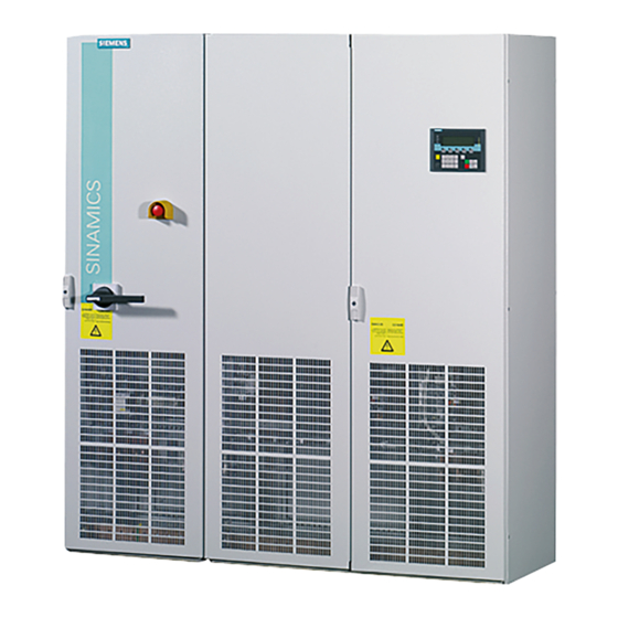
Device overview 2.3 Structure Structure The SINAMICS S150 drive converter cabinet units are characterized by their compact, modular, and service-friendly design. Line and motor-side components as well as additional monitoring devices can be installed in the converter cabinet units. A wide range of electrical and mechanical components enable the drive system to be optimized in line with prevailing requirements. - Page 23 Device overview 2.3 Structure Figure 2-2 Example of a cabinet unit (e.g. 132 kW, 400 V 3 AC) (certain components optional) Drive converter cabinet units Operating Instructions, 07/07, A5E00288214A...
-
Page 24: Wiring Principle
Device overview 2.4 Wiring principle Wiring principle Wiring principle: version A Figure 2-3 Wiring principle of the cabinet unit NOTICE The motor earth must be fed back directly to the cabinet unit. Drive converter cabinet units Operating Instructions, 07/07, A5E00288214A... -
Page 25: Type Plate
Device overview 2.5 Type plate Type plate Specifications on the type plate Figure 2-4 Type plate for the cabinet unit Date of manufacture The date of manufacture can be determined as follows: Table 2-1 Production year and month Letter/number Year of manufacture Letter/number Month of manufacture 2005... - Page 26 Device overview 2.5 Type plate Type plate data (from type plate above) Table 2-2 Data on the type plate Specification Value Explanation Input 3 AC Three-phase connection 380 – 480 V Rated input voltage 239 A Rated input current Output 3 AC Three-phase connection 0 –...
- Page 27 Device overview 2.5 Type plate Increase in degree of protection Degree of protection IP21 Degree of protection IP23 Degree of protection IP43 Degree of protection IP54 Mechanical options Base 100 mm high, RAL 7022 Cable compartment 200 mm high, RAL 7035 Line connection from above Motor connection from above Top-mounted crane transport assembly for cabinets...
- Page 28 Device overview 2.5 Type plate Drive converter cabinet units Operating Instructions, 07/07, A5E00288214A...
-
Page 29: Mechanical Installation
Mechanical installation Chapter content This chapter provides information on the following: ● The conditions for transporting, storing, and installing the cabinet unit ● Preparing and installing the cabinet unit Drive converter cabinet units Operating Instructions, 07/07, A5E00288214A... -
Page 30: Transportation And Storage
Mechanical installation 3.2 Transportation and storage Transportation and storage Transportation WARNING The following must be taken into account when the devices are transported: • The devices are heavy. Their center of gravity is displaced and they can be top heavy. •... - Page 31 • If you fail to contact them immediately, you may lose your right to claim compensation for the defects and damage. • If necessary, you can request the support of your local Siemens office. WARNING Damage in transit indicates that the device has been subject to unreasonable stress. The electrical safety of the device can no longer be ensured.
-
Page 32: Installation
Mechanical installation 3.3 Installation Installation WARNING To ensure that the devices operate safely and reliably, they must be properly installed and commissioned by qualified personnel, taking into account the warnings provided in these operating instructions. In particular, the general and national installation and safety guidelines for high-voltage installations (e.g. -
Page 33: Mechanical Installation: Checklist
Mechanical installation 3.3 Installation 3.3.1 Mechanical installation: checklist Use the following checklist to guide you through the mechanical installation procedure for the cabinet unit. Read the safety information at the start of this operating manual before you start working on the device. Note Check the boxes accordingly in the right-hand column if the activity applies to the cabinet unit in your scope of supply. - Page 34 Mechanical installation 3.3 Installation (option M54) can be installed in front of the hoods (IP54) and the ventilation grilles on the cabinet doors. The ambient conditions for the units in the operating rooms must not exceed the values of code F in accordance with EN 60146. At temperatures > 40°C (104°F) and altitudes > 2000 m, the devices must be derated.
-
Page 35: Installation
Mechanical installation 3.3 Installation 3.3.3 Installation Lifting the cabinet off the transport pallet The applicable local guidelines regarding the transportation of the cabinet from the transport palette to the installation location must be observed. A crane transport assembly (option M90) can also be fitted on the top of the cabinet. Installation Four holes for M12 screws are provided on each cabinet panel to secure the cabinet to the ground. - Page 36 Mechanical installation 3.3 Installation Attaching a canopy to increase the degree of protection to IP21 (option M21) 1. Remove the crane transport assembly (if fitted). 2. Attach the spacers to the roof of the cabinet at the positions specified. You may have to remove the protective grille.
- Page 37 Mechanical installation 3.3 Installation Fitting a hood to increase the degree of protection to IP23/IP43/IP54 (option M23/M43/M54) 1. Remove the crane transport assembly (if fitted). 2. Make sure that a perforated top cover is not fitted on the top of the cabinet (depending on production requirements, this can be fitted at a later stage).
-
Page 38: Infeed From Above (Option M13), Motor Connection From Above (Option M78)
Mechanical installation 3.3 Installation 3.3.5 Infeed from above (option M13), motor connection from above (option M78) Cable Entry from Above With options M13 and M78, the cabinet unit is equipped with an additional hood. The connection straps for the power cables, the clamping bar for mechanically securing the cables, an EMC shield bus, and a PE busbar are located within the hood. - Page 39 Mechanical installation 3.3 Installation Figure 3-3 Attaching the hood with M13 / M78 Drive converter cabinet units Operating Instructions, 07/07, A5E00288214A...
- Page 40 Mechanical installation 3.3 Installation Drive converter cabinet units Operating Instructions, 07/07, A5E00288214A...
-
Page 41: Electrical Installation
Electrical installation Chapter content This chapter provides information on the following: ● Establishing the electrical connections for the cabinet unit ● Adjusting the fan voltage and the internal power supply to local conditions (supply voltage) ● The customer terminal block and its interfaces ●... -
Page 42: Checklist For Electrical Installation
Electrical installation 4.2 Checklist for electrical installation Checklist for electrical installation Use the following checklist to guide you through the electrical installation procedure for the cabinet unit. Read the safety information at the start of this operating manual before you start working on the device. - Page 43 Electrical installation 4.2 Checklist for electrical installation Item Activity Fulfilled/Complete With an external auxiliary supply, the cable for the 230 V AC supply must be connected to terminal -X40 (see "Electrical installation / External supply of the auxiliary supply from a secure line").
- Page 44 Electrical installation 4.2 Checklist for electrical installation Item Activity Fulfilled/Complete Option K48 The SMC20 Sensor Module is used for determining the actual motor speed and the path length. SMC20 Sensor Module The following encoders are supported by the SMC20 Sensor Module: Incremental encoder sin/cos 1Vpp •...
- Page 45 Electrical installation 4.2 Checklist for electrical installation Item Activity Fulfilled/Complete Option L83 The PTC thermistor sensors (PTC resistor type A) must be connected to the thermistor motor protection unit -F127 at terminals T1 and T2 Thermistor for alarms (see "Electrical installation / Thermistor motor protection motor device (option L83/L84)").
- Page 46 Electrical installation 4.2 Checklist for electrical installation Required tools To install the connections, you will require: ● Spanner or socket spanner (w/f 10) ● Spanner or socket spanner (w/f 13) ● Spanner or socket spanner (w/f 16/17) ● Spanner or socket spanner (w/f 18/19) ●...
-
Page 47: Important Safety Precautions
Electrical installation 4.3 Important safety precautions Important safety precautions WARNING The cabinet units are operated with high voltages. All connection procedures must be carried out when the cabinet is de-energized. All work on the device must be carried out by trained personnel only. Non-observance of this warning can result in death, severe personal injury or substantial property damage. -
Page 48: Introduction To Emc
Electrical installation 4.4 Introduction to EMC Introduction to EMC What is meant by EMC? Electromagnetic compatibility (EMC) describes the capability of an electrical device to function satisfactorily in an electromagnetic environment without itself causing interference unacceptable for other devices in the environment. EMC therefore represents a quality feature for the ●... - Page 49 Electrical installation 4.4 Introduction to EMC Figure 4-2 Definition of categories C1 to C4 Table 4-1 Definition of environments 1 and 2 Definition of environments 1 and 2 Environment 1 Residential buildings or locations at which the drive system is connected to a public low-voltage supply network without a transformer.
-
Page 50: Emc-Compliant Design
Electrical installation 4.5 EMC-compliant design EMC-compliant design The following section provides some basic information and guidelines that will help you comply with the EMC and CE guidelines. cabinet assembly ● Connect painted or anodized metal components using toothed self-locking screws or remove the insulating layer. - Page 51 Electrical installation 4.5 EMC-compliant design ● Conductors or cables that carry signals of different classes must cross at right angles, especially if they carry sensitive signals that are subject to interference. – Class 1: unshielded cables for ≤ 60 V DC unshielded cables for ≤...
-
Page 52: Power Connections
Cable Lengths The maximum permissible cable lengths are specified for standard cable types or cable types recommended by SIEMENS. Longer cables can only be used after consultation. The listed cable length represents the actual distance between the converter and the motor, taking account factors such as parallel laying, current-carrying capacity, and the laying factor. -
Page 53: Connecting The Motor And Power Cables
Electrical installation 4.6 Power connections 4.6.2 Connecting the motor and power cables Connecting the motor and power cables on the cabinet unit Note The location of the connections is indicated in the layout diagrams provided in section 3. 1. Open the cabinet, remove the covers (if necessary) in front of the connection panel for motor cables (terminals U2/T1, V2/T2, W2/T3;... -
Page 54: Adjusting The Fan Voltage (-G1 -T10, -U1 -T10)
Electrical installation 4.6 Power connections Note If an incorrect rotating field was connected when the cables were installed, and the rotating field cannot be corrected by swapping the motor cables, it can be corrected when commissioning the drive via p1821 (rotating field direction reversal) by changing the rotating field and thus enabling a direction reversal (see section "Direction reversal"). - Page 55 Electrical installation 4.6 Power connections Figure 4-3 Setting terminals for the fan transformers (380 V – 480 V 3 AC / 660 V – 690 V 3 AC) Figure 4-4 Setting terminals for the fan transformers (500 V – 600 V 3 AC) The supply voltage assignments for making the appropriate setting on the fan transformer are indicated in the following tables.
- Page 56 Electrical installation 4.6 Power connections Table 4-4 Supply voltage assignments for setting the fan transformer (380 V – 480 V 3AC) Supply voltage Fan transformer tap (-G1-T10, -U1-T10) 380 V ± 10% 380 V 400 V ± 10% 400 V 440 V ±...
-
Page 57: Adjusting The Internal Power Supply (-A1-T10)
Electrical installation 4.6 Power connections 4.6.4 Adjusting the internal power supply (-A1-T10) A transformer is installed in the line connection module (-A1-T10) for the internal 230 V AC power supply for the cabinet. The location of the transformer is indicated in the layout diagrams supplied. -
Page 58: Removing The Connection Bracket For The Interference-Suppression Capacitor With Operation From An Ungrounded Supply
Electrical installation 4.6 Power connections 4.6.5 Removing the connection bracket for the interference-suppression capacitor with operation from an ungrounded supply If the cabinet unit is operated from an ungrounded supply/IT system, the connection bracket for the interference-suppression capacitor of the active interface modules (-A2) must be removed. -
Page 59: External Supply Of The Auxiliary Supply From A Secure Line
Electrical installation 4.7 External supply of the auxiliary supply from a secure line External supply of the auxiliary supply from a secure line Description An external auxiliary supply is always recommended if communication and closed-loop control are to be independent of the supply system. An external auxiliary supply is particularly recommended for low-power lines susceptible to short-time voltage dips or power failures. -
Page 60: Signal Connections
Electrical installation 4.8 Signal connections Signal connections 4.8.1 Customer terminal block (-A60) Note The factory setting and description of the customer terminal blocks can be found in the circuit diagrams. The location of the customer terminal block in the cabinet unit is indicated in the layout diagram. - Page 61 Electrical installation 4.8 Signal connections Overview -X540 SIEMENS -X520 -X530 -X541 S5.0 S5.1 -X521 -X542 -X522 Figure 4-7 Customer terminal block TM31 Drive converter cabinet units Operating Instructions, 07/07, A5E00288214A...
- Page 62 Electrical installation 4.8 Signal connections Figure 4-8 Connection overview of customer terminal block TM31 Drive converter cabinet units Operating Instructions, 07/07, A5E00288214A...
- Page 63 Electrical installation 4.8 Signal connections Note The digital inputs (terminals -X520 and -X530) in the example are powered by the internal 24 V supply of the customer terminal block (terminal -X540). The two groups of digital inputs (optocoupler inputs) have a common reference potential (ground reference M1 or M2).
- Page 64 Electrical installation 4.8 Signal connections X530: 4 digital inputs Table 4-11 Terminal block X530 Terminal Designation Technical specifications DI 4 Voltage: - 3 V to 30 V Current input (typical): 10 mA up to 24 V DI 5 With electrical isolation: The reference potential is terminal M2 DI 6 Level: DI 7...
- Page 65 Electrical installation 4.8 Signal connections S5: Selector for voltage/current AI0, AI1 Table 4-13 Selector for voltage/current S5 Switch Function Technical specifications S5.0 Selector voltage/current AI0 Voltage Current S5.1 Selector voltage/current AI1 X522: 2 analog outputs, temperature sensor connection Table 4-14 Terminal block X522 Terminal Designation...
- Page 66 Electrical installation 4.8 Signal connections X541: 4 non-isolated digital inputs/outputs Table 4-16 Terminal strip X541 Terminal Designation Technical specifications As input: Voltage: -3 V to 30 V DI/DO 8 Current consumption (typical): 10 mA at 24 V DC DI/DO 9 As output: DI/DO 10 Max.
-
Page 67: Other Connections
Electrical installation 4.9 Other connections Other connections Depending on the options installed, further connections have to be established, for example, dV/dt filter, sinusoidal filter, connection for external auxiliary equipment, main circuit breaker including fuses or circuit breaker, EMERGENCY STOP button, cabinet illumination with service socket, anti-condensation heating for cabinet, contactor combination (EMERGENCY STOP), thermistor motor protection unit, PT100 evaluation unit, insulation monitor, encoder evaluator, and NAMUR option. - Page 68 Electrical installation 4.9 Other connections Table 4-18 Accommodating the voltage limiting network in the cabinet or in an additional cabinet Voltage range Installation of the dV/dt filter Installation of the VPL in an Installation of the VPL in an with Voltage Peak Limiter additional cabinet, 400 mm additional cabinet, 600 mm within the converter cabinet...
-
Page 69: Sinusoidal Filter (Option L15)
If a filter cannot be parameterized (p0230 ≠ 3), this means that a filter has not been provided for the cabinet unit. In this case, the cabinet unit must not be operated with a sinusoidal filter. Table 4-19 Technical specifications for sinusoidal filters with SINAMICS S150 Order no. Voltage Pulse frequency... - Page 70 In the event of commissioning using the STARTER or AOP30, the sine-wave filter must be activated by means of appropriate selection screenforms or dialog boxes, see the section titled "Commissioning". The following parameters are changed automatically during commissioning. Table 4-20 Parameter settings for sinusoidal filters with SINAMICS S150 Parameter Name Setting p0233...
-
Page 71: Connection For External Auxiliary Equipment (Option L19)
Electrical installation 4.9 Other connections 4.9.3 Connection for external auxiliary equipment (Option L19) Description This option includes an outgoing circuit fused at max. 10 A for external auxiliary equipment (e.g. separately-driven fan for motor). The voltage is tapped at the converter input upstream of the main contactor/circuit-breaker and, therefore, has the same level as the supply voltage. - Page 72 Electrical installation 4.9 Other connections Circuit proposal for controlling the auxiliary contactor from within the converter The following circuit, for example, can be used if the auxiliary contactor is to be controlled from within the converter. The “Operation” message is then no longer available for other purposes.
-
Page 73: Main Switch Incl. Fuses Or Main Circuit Breaker (Option L26)
Electrical installation 4.9 Other connections 4.9.4 Main switch incl. fuses or main circuit breaker (option L26) Description Up to 800 A, a load interrupter with externally-mounted fuses is used as the main circuit breaker. Above 800 A, the standard circuit breaker is used. The circuit breaker is energized and supplied within the converter. -
Page 74: Emergency Stop Pushbutton (Option L45)
Electrical installation 4.9 Other connections 4.9.5 EMERGENCY STOP pushbutton (option L45) Description The EMERGENCY STOP pushbutton with protective collar is integrated in the door of the cabinet unit. The contacts of the pushbutton are connected to terminal block –X120. Category 0 and 1 EMERGENCY STOP functions can be activated in conjunction with options L57, L59, and L60. -
Page 75: Cabinet Illumination With Service Socket (Option L50)
Electrical installation 4.9 Other connections 4.9.6 Cabinet illumination with service socket (option L50) Description A universal lamp with an integrated service socket is installed in each cabinet panel. The power supply for the cabinet illumination and socket must be provided externally and fused at max. -
Page 76: Cabinet Anti-Condensation Heating (Option L55)
Electrical installation 4.9 Other connections 4.9.7 Cabinet anti-condensation heating (option L55) Description The anti-condensation heating is used at low ambient temperatures and high levels of humidity to prevent condensation forming. One 100 W heater is installed for a 400 mm and 600 mm cabinet panel, and two 100 W heaters for an 800/1000 and 1200 mm cabinet panel. -
Page 77: Emergency Stop Category 0; 230 V Ac Or 24 V Dc (Option L57)
Electrical installation 4.9 Other connections 4.9.8 EMERGENCY STOP category 0; 230 V AC or 24 V DC (option L57) Description EMERGENCY STOP category 0 for uncontrolled stop to EN 60204. This function involves disconnecting the cabinet unit from the supply via the line contactor bypassing the electronics by means of a safety combination to EN 60204-1. -
Page 78: Emergency Stop Category 1; 230 V Ac (Option L59)
Electrical installation 4.9 Other connections 4.9.9 EMERGENCY STOP category 1; 230 V AC (option L59) Description EMERGENCY STOP category 1 for controlled stop to EN 60 204. This function stops the drive by means of a quick stop along a deceleration ramp that must be parameterized. The cabinet unit is then disconnected from the power supply via the line contactor, which bypasses the electronics by means of a safety combination (to EN 60 204-1). -
Page 79: Emergency Stop Category 1; 24 V Dc (Option L60)
Electrical installation 4.9 Other connections 4.9.10 EMERGENCY STOP category 1; 24 V DC (option L60) Description EMERGENCY STOP category 1 for controlled stop to EN 60 204. This function stops the drive by means of a quick stop along a deceleration ramp that must be parameterized. The cabinet unit is then disconnected from the power supply via the line contactor, bypassing the electronics by means of a safety combination (to EN 60 204-1). -
Page 80: Kw Braking Unit (Option L61/L64); 50 Kw Braking Unit (Option L62/L65)
Electrical installation 4.9 Other connections 4.9.11 25 kW braking unit (option L61/L64); 50 kW braking unit (option L62/L65) Description Under normal circumstances, the braking energy is supplied back to the line. If a controlled stop is also required in the event of a power failure, however, additional braking units can be provided. - Page 81 Electrical installation 4.9 Other connections CAUTION A ventilation clearance of 200 m must be maintained on all sides of the braking resistor (with ventilation grilles). Table 4-30 Dimensions of the braking resistors Unit 25 kW resistor (option L61/L64) 50 kW resistor (option L62/L65) Length Width Height...
- Page 82 Electrical installation 4.9 Other connections Connecting the braking resistor WARNING The cables must only be connected to terminal block -X5 when the cabinet unit is switched off and the DC link capacitors are discharged. CAUTION The braking resistor cables must be laid in such a way that they are short-circuit and ground-fault proof.
- Page 83 Electrical installation 4.9 Other connections Commissioning When commissioning via STARTER, parameters are assigned to "external fault 3" and acknowledged automatically when option L61, L62, L64, or L65 is selected. When commissioning via AOP30, the parameter entries required have to be set subsequently.
- Page 84 Electrical installation 4.9 Other connections Duty cycles Figure 4-12 Duty cycles for the braking resistors Threshold switch The response threshold at which the braking unit is activated and the DC link voltage generated during braking are specified in the following table. Note Since the braking energy is normally supplied back to the line and the braking chopper is only to be activated in the event of a power failure, the default threshold value setting should...
- Page 85 Electrical installation 4.9 Other connections Table 4-33 Response thresholds of the braking units Rated voltage Response Switch Remark threshold position 380 V - 480 V 673 V 774 V is the default factory setting. With supply voltages of between 380 V and 400 V, the response threshold can be set to 673 V to reduce the voltage 774 V stress on the motor and converter.
-
Page 86: Thermistor Motor Protection Unit (Option L83/L84)
Electrical installation 4.9 Other connections 4.9.12 Thermistor motor protection unit (option L83/L84) Description This option includes the thermistor motor protection unit (with PTB approval) for PTC thermistor sensors (PTC resistor type A) for warning and shutdown. The power supply for the thermistor motor protection unit is provided inside the converter where the evaluation is also performed. -
Page 87: Pt100 Evaluation Unit (Option L86)
Electrical installation 4.9 Other connections 4.9.13 PT100 evaluation unit (option L86) Description Note The PT100 evaluation unit and the parameters for the measurement channels are described in the lug "Additional operating instructions". The PT100 evaluation unit can monitor up to six sensors. The sensors can be connected in a two or three-wire system. - Page 88 Electrical installation 4.9 Other connections Connection Table 4-36 Terminal block -A1-A140 – connection for evaluation unit PT100 resistors Terminal Designation Technical specifications T11-T13 90–240 V AC/DC; PT100; sensor 1; group 1 T21-T23 90–240 V AC/DC; PT100; sensor 2; group 1 T31-T33 90–240 V AC/DC;...
-
Page 89: Insulation Monitor (Option L87)
Electrical installation 4.9 Other connections 4.9.14 Insulation monitor (option L87) Description The device monitors the entire electrically connected circuit for insulation faults. The insulation resistance as well as all the insulation faults that occur in the DC link and on the motor side of the cabinet are detected. -
Page 90: Communication Board Ethernet Cbe20 (Option G33)
Electrical installation 4.9 Other connections Diagnosis Messages output during operation and in the event of faults (meaning of LEDs on –A101) are described in "Additional Operating Instructions" in the operating manual. 4.9.15 Communication Board Ethernet CBE20 (option G33) Description Interface module CBE20 is used for communication via PROFINET. The module is delivered mounted in a supplementary pack on the CU320 Control Unit and must be installed line-side in the option slot of the CU320 Control Unit. - Page 91 Electrical installation 4.9 Other connections X1400 Ethernet interface Table 4-38 Connector X1400, port 1 - 4 Signal name Technical specifications Receive data + Receive data - Transmit data + Reserved, do not use Reserved, do not use Transmit data - Reserved, do not use Reserved, do not use Screened backshell...
-
Page 92: Smc10 Sensor Module For Determining The Actual Motor Speed And The Rotor Position Angle (Option K46)
Electrical installation 4.9 Other connections 4.9.16 SMC10 Sensor Module for determining the actual motor speed and the rotor position angle (option K46) 4.9.16.1 Description The SMC10 Sensor Module is used for determining the actual motor speed and the rotor position angle. The signals emitted by the resolver are converted here and made available to the closed-loop controller via the DRIVE-CLiQ interface for evaluation purposes. -
Page 93: Connection
Electrical installation 4.9 Other connections 4.9.16.2 Connection X520: Encoder connection Table 4-39 Encoder connection X520 Signal name Technical specifications Reserved, do not use Reserved, do not use A (sin+) Resolver signal A A* (sin-) Inverted resolver signal A Ground Ground (for internal shield) B (cos+) Resolver signal B B* (cos-) -
Page 94: Connection Example
Electrical installation 4.9 Other connections 4.9.16.3 Connection example Connection example: Resolver, 8 pole Figure 4-16 Connection example: Resolver, 8 pole Drive converter cabinet units Operating Instructions, 07/07, A5E00288214A... - Page 95 Electrical installation 4.9 Other connections Parameter settings Table 4-40 Parameter settings for 8-pole resolver on SMC10 Parameter Name Value p0400[0] Enc type selection Resolver 4 speed (1004) p0404[0] Encoder configuration effective 800010(hex) p0404[0].0 Linear encoder p0404[0].1 Absolute encoders p0404[0].2 Multiturn encoder p0404[0].3 Track A/B square-wave p0404[0].4...
-
Page 96: Smc20 Sensor Module For Determining The Actual Motor Speed And The Path Length (Option K48)
Electrical installation 4.9 Other connections 4.9.17 SMC20 Sensor Module for determining the actual motor speed and the path length (option K48) 4.9.17.1 Description Description The SMC20 Sensor Module is used for determining the actual motor speed and the path length. The signals emitted by the rotary pulse encoder are converted here and made available closed-loop controller via the DRIVE-CLiQ interface for evaluation purposes. -
Page 97: Connection
Electrical installation 4.9 Other connections 4.9.17.2 Connection X520: Encoder connection Table 4-41 Encoder connection X520 Signal name Technical specifications P encoder Encoder supply M encoder Ground for encoder power supply Incremental signal A Inverted incremental signal A Ground Ground (for internal shield) Incremental signal B Inverted incremental signal B Ground... -
Page 98: Connection Example
Electrical installation 4.9 Other connections 4.9.17.3 Connection example Connection example: Incremental encoder sin/cos 1 Vpp, 2048 Figure 4-18 Connection example: Incremental encoder sin/cos 1 Vpp, 2048 Drive converter cabinet units Operating Instructions, 07/07, A5E00288214A... - Page 99 Electrical installation 4.9 Other connections Parameter settings Table 4-42 Parameter settings for incremental encoder sin/cos on SMC20 Parameter Name Value p0400[0] Enc type selection 2048, 1 Vpp, A/B R (2002) p0404[0] Encoder configuration effective 101010(hex) p0404[0].0 Linear encoder p0404[0].1 Absolute value encoder p0404[0].2 Multiturn encoder p0404[0].3...
-
Page 100: Smc30 Sensor Module For Detecting The Actual Motor Speed (Option K50)
Electrical installation 4.9 Other connections 4.9.18 SMC30 Sensor Module for detecting the actual motor speed (option K50) 4.9.18.1 Description The SMC30 Sensor Module is used for determining the actual motor speed. The signals emitted by the rotary pulse encoder are converted here and made available closed-loop controller via the DRIVE-CLiQ interface for evaluation purposes. - Page 101 Electrical installation 4.9 Other connections For encoders with a 5 V supply at X521/X531, the cable length is dependent on the encoder current (this applies cable cross-sections of 0.5 mm²): Figure 4-19 Signal cable length as a function of the sensor current consumption Drive converter cabinet units Operating Instructions, 07/07, A5E00288214A...
- Page 102 Electrical installation 4.9 Other connections Figure 4-20 SMC30 Sensor Module Drive converter cabinet units Operating Instructions, 07/07, A5E00288214A...
-
Page 103: Connection
Electrical installation 4.9 Other connections 4.9.18.2 Connection X520: Encoder connection 1 for TTL/SSI encoder with open-circuit monitoring Table 4-45 Encoder connection X520 Signal name Technical specifications Reserved, do not use SSI_CLK SSI clock SSI_XCLK Inverted SSI clock P_Encoder 5 V / 24 V Encoder power supply P_Encoder 5 V / 24 V Encoder power supply... - Page 104 Electrical installation 4.9 Other connections X521 / X531: Encoder connection 2 for HTL/TTL/SSI encoder with open-circuit monitoring Table 4-46 Encoder connection X521 Terminal Signal name Technical specifications Incremental signal A Inverted incremental signal A Incremental signal B Inverted incremental signal B Reference signal R Inverted reference signal R CTRL...
-
Page 105: Connection Examples
Electrical installation 4.9 Other connections 4.9.18.3 Connection examples Connection example 1: HTL encoder, bipolar, without zero marker -> p0405 = 9 (hex) Figure 4-21 Connection example 1: HTL encoder, bipolar, without zero marker Connection example 2: TTL encoder, unipolar, without zero marker -> p0405 = A (hex) Figure 4-22 Connection example 2: TTL encoder, unipolar, without zero marker Drive converter cabinet units... -
Page 106: Voltage Sensing Module For Determining The Actual Motor Speed And The Phase Angle (Option K51)
Electrical installation 4.9 Other connections 4.9.19 Voltage Sensing Module for determining the actual motor speed and the phase angle (option K51) Voltage recording module VSM10 is used to operate a permanent-field synchronous machine without encoder with the requirement for switching to a machine which is already running (capture function). -
Page 107: Terminal Module For Activation Of "Safe Torque Off" And "Safe Stop 1" (Option K82)
98/37/EC, EN 60204-1 as well as in DIN EN ISO 13849-1 category 3 (formerly EN954-1) are satisfied. The certification of option K82 is in process. A list of certified components is available on request from your local Siemens office. Recommended application This option is used when: ●... - Page 108 Electrical installation 4.9 Other connections Functional principle Two independent channels of the integrated safety function are activated via the relays (K41, K42). The relay K41 activates the signal to the control unit that is necessary for the safety function and the relay K42 on the Power Module or Motor Module respectively The selection and deselection must be executed concurrently.
- Page 109 Electrical installation 4.9 Other connections Control circuit: Rated voltage: 24 - 230 V DC/AC (0.85 … 1.1 x Us) Max. line length (applies for current and return conductor): ● AC (line capacity: 300 pF/m): – 24 V: 5,000 m – 110 V: 800 m –...
- Page 110 Electrical installation 4.9 Other connections -K42 -K41 -X41 Figure 4-23 Circuit terminal module for option K82 A switch in accordance with ISO ISO 13850/ EN 418, positive opening in accordance with EC 60947-5-1, or a certified safety controller must be used as activation element. Note The terminal -X41:10 is permanently connected to the digital input DI7.
-
Page 111: Namur Terminal Block (Option B00)
Electrical installation 4.9 Other connections 4.9.22 NAMUR terminal block (option B00) Description The terminal block is designed in accordance with the requirements and guidelines defined by the standards association for measurement and control systems in the chemical industry (NAMUR – recommendation NE37), that is, certain device functions are assigned to fixed terminals. - Page 112 Electrical installation 4.9 Other connections Terminal Designation Default value Comments Power Disconnection EMERGENCY STOP circuit Ready Relay output (NO contact) Motor turning Relay output (NO contact) DO (NO) Fault Relay output (two-way contact) DO (COM) DO (NC) 50/51 AI 0/4-20 mA Speed setpoint Default: 4 to 20 mA 60/61...
-
Page 113: Electrically Separate 24 V Dc Power Supply For Namur (Option B02)
Electrical installation 4.9 Other connections 4.9.23 Electrically separate 24 V DC power supply for NAMUR (option B02) Description If the customer cannot provide a separate 24 V DC supply (PELV), this option enables a second power supply to be installed to provide the PELV (terminal assignment as option B00, 24 V infeed at terminal –A1-X1:1,2,3 no longer needed). - Page 114 Electrical installation 4.9 Other connections Drive converter cabinet units Operating Instructions, 07/07, A5E00288214A...
-
Page 115: Commissioning
Commissioning Chapter content This chapter provides information on the following: ● An overview of the operator panel functions ● Initial commissioning of the cabinet (initialization) – Entering the motor data (drive commissioning) – Entering the most important parameters (basic commissioning), concluding with the motor ID ●... -
Page 116: Starter Commissioning Tool
Commissioning 5.2 STARTER commissioning tool STARTER commissioning tool Description You can use the STARTER commissioning tool to configure and commission SINAMICS drives and drive systems. The drive can be configured using the STARTER drive configuration Wizard. Note This chapter shows you how to carry out commissioning using STARTER. STARTER features a comprehensive online help function, which provides detailed explanations of all the processes and available system settings. -
Page 117: The Starter User Interface
Commissioning 5.2 STARTER commissioning tool 5.2.2 The STARTER user interface STARTER features four operating areas: Figure 5-1 STARTER operating areas Operating area Explanation 1: Toolbars In this area, you can access frequently used functions via the icons. 2: Project navigator The elements and projects available in the project are displayed here. -
Page 118: Procedure For Commissioning Via Starter
Commissioning 5.3 Procedure for commissioning via STARTER Procedure for commissioning via STARTER Basic procedure using STARTER STARTER uses a sequence of dialog screens for entering the required drive unit data. NOTICE These dialog screens contain default settings, which you may have to change according to your application and configuration. - Page 119 Commissioning 5.3 Procedure for commissioning via STARTER Accessing the STARTER project Wizard Figure 5-2 Main screen of the STARTER parameterization and commissioning tool 1. Close the "STARTER Getting Started Drive Commissioning" screen by choosing HTML Help > Close. Note When you deactivate the Display Wizard during start checkbox, the project Wizard is no longer displayed the next time you start STARTER.
- Page 120 Commissioning 5.3 Procedure for commissioning via STARTER The STARTER project Wizard Figure 5-3 STARTER project Wizard 2. Click Arrange drive units offline... in the STARTER project Wizard. Figure 5-4 Create new project Drive converter cabinet units Operating Instructions, 07/07, A5E00288214A...
- Page 121 Commissioning 5.3 Procedure for commissioning via STARTER 3. Enter a project name and, if necessary, the author, memory location and a comment. 4. Click Continue > to set up the PG/PC interface. Figure 5-5 Set up interface Note The online connection to the drive unit can only be established via PROFIBUS. 5.
- Page 122 Commissioning 5.3 Procedure for commissioning via STARTER Figure 5-6 Setting the interface Note To parameterize the interface, you must install an appropriate interface card, e.g., PC adapter (PROFIBUS). Drive converter cabinet units Operating Instructions, 07/07, A5E00288214A...
- Page 123 Commissioning 5.3 Procedure for commissioning via STARTER Figure 5-7 Setting the interface - properties NOTICE You must activate PG/PC is the only master on bus if no other master (PC, S7, etc.) is available on the bus. Note Projects can be created and PROFIBUS addresses for the drive objects assigned even if a PROFIBUS interface has not been installed on the PC.
- Page 124 Commissioning 5.3 Procedure for commissioning via STARTER Figure 5-8 Setting the interface 7. Click Continue > to set up a drive unit in the project Wizard. Figure 5-9 Inserting the drive unit Drive converter cabinet units Operating Instructions, 07/07, A5E00288214A...
- Page 125 Commissioning 5.3 Procedure for commissioning via STARTER 8. Choose the following data from the list fields: Device: Sinamics Type: S150 Version: v2.5 Bus address: the corresponding bus address for the cabinet unit. The entry in field Name: field is user defined. 9: Click Insert The selected drive unit is displayed in a preview window in the project wizard.
- Page 126 Commissioning 5.3 Procedure for commissioning via STARTER Figure 5-11 Summary 11. Click Complete to finish creating a new drive unit project. Drive converter cabinet units Operating Instructions, 07/07, A5E00288214A...
-
Page 127: Configuring The Drive Unit
Commissioning 5.3 Procedure for commissioning via STARTER 5.3.2 Configuring the drive unit In the project navigator, open the component that contains your drive unit. Figure 5-12 Project navigator – configuring the drive unit 1. In the project navigator, click the plus sign next to the drive unit that you want to configure. The plus sign becomes a minus sign and the drive unit configuration options are displayed as a tree below the drive unit. - Page 128 Commissioning 5.3 Procedure for commissioning via STARTER Configuring the drive unit Figure 5-13 Configuring the drive unit 3. Under Voltage selection, choose the correct voltage. Under Cooling type choose the correct cooling type for your drive unit. Note In this step, you make a preliminary selection of the cabinet units. You do not define the supply voltage yet.
- Page 129 Commissioning 5.3 Procedure for commissioning via STARTER Choosing the options Figure 5-14 Choosing the options 6. In the Options selection combination field, choose the options that belong to your drive unit by clicking the appropriate checkboxes (see type plate). CAUTION If a sinusoidal filter (option L15) is connected, it must be activated when the options are selected to prevent the filter from being destroyed.
- Page 130 Commissioning 5.3 Procedure for commissioning via STARTER Note Check your options carefully against the options specified on the type plate. Internal interconnections are established by the Wizard on the basis of the options selected, which means that you cannot change the selected options with < Back. If you made an incorrect entry, delete the complete drive unit from the project navigator and create a new one.
- Page 131 Commissioning 5.3 Procedure for commissioning via STARTER Configure the infeed Figure 5-15 Configure the infeed 8. Choose whether the line and DC link identification function is to be activated during initial start-up. (Recommendation: "Activate identification" = "Yes") 9. Specify the Device connection voltage. 10.
- Page 132 Commissioning 5.3 Procedure for commissioning via STARTER Selecting the control structure Figure 5-16 Selecting the control structure 11. Select the required data: ● Function modules: – Technology controller – Basic positioner – Extended messages/monitoring Drive converter cabinet units Operating Instructions, 07/07, A5E00288214A...
- Page 133 Commissioning 5.3 Procedure for commissioning via STARTER ● Control method: choose one of the following open-loop/closed-loop control types: – Torque control (sensorless) – Torque control (with encoder) – Speed control (sensorless) – Speed control (with encoder) – I/f control with fixed current –...
- Page 134 Commissioning 5.3 Procedure for commissioning via STARTER Configuring the drive unit properties Figure 5-17 Configuring the drive unit properties 13. Under Standard, choose the appropriate standard for your motor, whereby the following is defined: ● IEC motor (50 Hz, SI unit): line frequency 50 Hz, motor data in kW ●...
- Page 135 Commissioning 5.3 Procedure for commissioning via STARTER Configuring the motor and selecting the motor type Figure 5-18 Configuring the motor and selecting the motor type 17. In the Name field, enter a name of your choice for the motor. 18. From the selection box next to Motor type: select the appropriate motor for your application Drive converter cabinet units Operating Instructions, 07/07, A5E00288214A...
- Page 136 Commissioning 5.3 Procedure for commissioning via STARTER Note The steps described below also apply to induction motors. When commissioning a permanent-field synchronous motor, there are a few special conditions which are detailed in a separate chapter (see "Closed-loop control"). 19. Click Continue >. Drive converter cabinet units Operating Instructions, 07/07, A5E00288214A...
- Page 137 Commissioning 5.3 Procedure for commissioning via STARTER Configuring the motor and entering motor data Figure 5-19 Configuring the motor and entering motor data 20. Enter the motor data (see motor type plate). 21. If necessary, check Do you want to enter the optional data? 22.
- Page 138 Commissioning 5.3 Procedure for commissioning via STARTER Note Click Template to open another selection screenform where you can choose the motor used in your application from a long list of standard motor types. Select a motor from the list to enter the data stored in the system for that motor automatically in the data fields.
- Page 139 Commissioning 5.3 Procedure for commissioning via STARTER Configuring the motor and entering optional data Figure 5-20 Entering optional motor data 24. If necessary, enter the optional motor data. 25. Click Continue >. Drive converter cabinet units Operating Instructions, 07/07, A5E00288214A...
- Page 140 Commissioning 5.3 Procedure for commissioning via STARTER Configuring the motor and entering the equivalent circuit diagram data Figure 5-21 Entering equivalent circuit diagram data 26. If necessary, enter the equivalent circuit diagram data. 27. Click Continue >. Drive converter cabinet units Operating Instructions, 07/07, A5E00288214A...
- Page 141 Commissioning 5.3 Procedure for commissioning via STARTER Calculating the motor/controller data Figure 5-22 Calculating the motor/controller data 28. In Calculation of the motor/controller data, choose the appropriate default settings for your device configuration. Note If the equivalent circuit diagram data was entered manually (see "Entering the equivalent circuit diagram data"), the motor/controller data should be calculated without calculating the equivalent circuit diagram data.
- Page 142 Commissioning 5.3 Procedure for commissioning via STARTER Configuring the motor holding brake Figure 5-23 Configuring the motor holding brake 30. Under Holding brake configuration , choose the appropriate settings for your device configuration. 31. Click Continue >. Drive converter cabinet units Operating Instructions, 07/07, A5E00288214A...
- Page 143 Commissioning 5.3 Procedure for commissioning via STARTER Entering the encoder data (option K46 / K48 / K50) Note If you have specified option K46, K48, or K50 (SMC10, SMC20, or SMC30 Sensor Module), the following screen is displayed in which you can enter the encoder data. Figure 5-24 Entering the encoder data (option K46) Drive converter cabinet units...
- Page 144 Commissioning 5.3 Procedure for commissioning via STARTER Figure 5-25 Entering the encoder data (option K48) Drive converter cabinet units Operating Instructions, 07/07, A5E00288214A...
- Page 145 Commissioning 5.3 Procedure for commissioning via STARTER Figure 5-26 Entering the encoder data (option K50) 32. In the Name field, enter a name of your choice. 33. Click the Select standard encoder from list radio button and select one of the available encoders.
- Page 146 Commissioning 5.3 Procedure for commissioning via STARTER 34. To enter special encoder configurations, click the Enter data radio button and then the Encoder data button. The following screen (in this case an example for the HTL encoder) is displayed in which you can enter the required data. Figure 5-27 Entering encoder data –...
- Page 147 Commissioning 5.3 Procedure for commissioning via STARTER Default settings for setpoints / command sources Figure 5-28 Default settings for setpoints / command sources 33. Under Command sources and Setpoint sources , choose the appropriate settings for your device configuration. Drive converter cabinet units Operating Instructions, 07/07, A5E00288214A...
- Page 148 TM31 terminals Motorized potentiometer Fixed setpoint Note With SINAMICS S150, only CDS0 is normally used as a default setting for the command and setpoint sources. Make sure that the selected default setting is compatible with the actual system configuration. You cannot retrospectively change the selected default setting with <...
- Page 149 – "Standard drive (VECTOR)": edge modulation is not enabled (default) ● Motor identification: "Motor data identification with motor running" is normally the appropriate default setting for SINAMICS S150, especially if an encoder is used for speed control. 36. Click Continue >. Drive converter cabinet units...
- Page 150 Commissioning 5.3 Procedure for commissioning via STARTER Selecting the PROFIBUS message frame Figure 5-30 Selecting the PROFIBUS message frame 37. In the PROFIBUS PZD message frame field, select the PROFIBUS message frame type. Message frame types ● Standard message frame 1 ●...
- Page 151 Commissioning 5.3 Procedure for commissioning via STARTER Entering important parameters Figure 5-31 Important parameters 39. Enter the required parameter values. Note STARTER provides tool tips if you position your cursor on the required field without clicking in the field. 40. Click Continue >. Drive converter cabinet units Operating Instructions, 07/07, A5E00288214A...
- Page 152 Commissioning 5.3 Procedure for commissioning via STARTER Summary of the drive unit data Figure 5-32 Summary of the drive unit data 41. You can use the Copy text to clipboard function to copy the summary of the drive unit data displayed on the screen to a word processing program so that you can edit it further. 42.
-
Page 153: Starting The Drive Project
Commissioning 5.3 Procedure for commissioning via STARTER 5.3.3 Starting the drive project You have created a project and saved it to your hard disk. You now have to transfer your project configuration data to the drive unit. Transferring the STARTER project to the drive unit To transfer the STARTER project you created offline to the drive unit, carry out the following steps: Step... -
Page 154: Connection Via Serial Interface
Commissioning 5.3 Procedure for commissioning via STARTER Results of the previous steps ● You have created a drive unit project offline using STARTER. ● You have saved the project data to the hard disk on your PC. ● You have transferred the project data to the drive unit. ●... - Page 155 Commissioning 5.3 Procedure for commissioning via STARTER Figure 5-33 Setting the interface 3. On CU320, set bus address "3" on the Profibus address switch. 4. When creating the drive unit, also set bus address "3". Drive converter cabinet units Operating Instructions, 07/07, A5E00288214A...
- Page 156 Commissioning 5.3 Procedure for commissioning via STARTER Figure 5-34 Setting the bus address Note The bus addresses on CU320 and on the PC must not be set the same. 5. The connecting cable from CU320 to AOP30 must be disconnected on CU320. A null modem cable must be used here to connect the PC (COM interface) and CU320.
-
Page 157: The Aop30 Operator Panel
Commissioning 5.4 The AOP30 operator panel The AOP30 operator panel Description An operator panel is located in the cabinet door of the cabinet unit for operating, monitoring, and commissioning tasks. It has the following features: ● Graphical, back-lit LCD for plain-text display and a "bar display" of process variables ●... -
Page 158: First Commissioning
Commissioning 5.5 First commissioning First commissioning 5.5.1 First commissioning Start screen When the system is switched on for the first time, the Control Unit (CU320) is initialized automatically. The following screen is displayed: Figure 5-36 Initial screen When the system boots up, the parameter descriptions are loaded into the operating field from the CompactFlash card. - Page 159 Commissioning 5.5 First commissioning Once the system has successfully ramped up, the drive has to be commissioned when the system is switched on for the first time after it has been delivered. The converter can then be switched on. When the system is then ramped up again, it can be operated immediately. Navigation within the interactive screens Within an interactive screen, the selection boxes can usually be selected using the <F2>...
-
Page 160: Basic Commissioning
Commissioning 5.5 First commissioning 5.5.2 Basic commissioning Entering the motor data During initial commissioning, you have to enter motor data using the operator panel. Use the data shown on the motor type plate. Figure 5-38 Example of a motor type plate Table 5-1 Motor data Parameter no. - Page 161 Commissioning 5.5 First commissioning First commissioning: infeed Table 5-2 Entering the infeed data Enter the line infeed voltage in V and the line frequency in Hz. Select the line identification (do not change the default setting). Entry for the origin of the ON/OFF1 command.
- Page 162 Commissioning 5.5 First commissioning Basic commissioning: Selecting the motor type and entering the motor data You can select the motor standard and type in the dialog screen. The following is defined for the motor standard: 0: Line frequency 50 Hz, motor data in kW 1: line frequency 60 Hz, motor data in hp The following selection options are available for the motor type:...
- Page 163 Commissioning 5.5 First commissioning Basic commissioning: Entering the encoder data (if available) When the SMC10/SMC20/SMC30 is connected for encoder evaluation (with options K46, K48, and K50), it is recognized by the AOP30 and a screen is displayed in which you can enter the encoder data. Navigate within the selection fields with <F2>...
- Page 164 Commissioning 5.5 First commissioning Encoders for SMC30: 3001: 1024 HTL A/B R at X521/X531 3002: 1024 TTL A/B R at X521/X531 3003: 2048 HTL A/B R at X521/X531 3005: 1024 HTL A/B at X521/X531 3006: 1024 TTL A/B at X521/X531 3007: 2048 HTL A/B at X521/X531 3008:...
- Page 165 Commissioning 5.5 First commissioning CAUTION Once the encoder has been commissioned, the supply voltage (5/24 V) set for the encoder is activated on the SMC30 module. If a 5 V encoder is connected and the supply voltage has not been set correctly via p0404 (bit 20 = "Yes", bit 21 = "No"), the encoder may be damaged.
- Page 166 Commissioning 5.5 First commissioning Basic commissioning: Entering the basic parameters Entering the basic commissioning parameters: If a sinusoidal filter (option L15) is connected, it must be activated in p0230 (p0230 = 3) otherwise it could be destroyed. p0700: Preset command source 5: PROFIdrive 6: TM31 terminals 7: Namur...
- Page 167 Commissioning 5.5 First commissioning NOTICE A filter at the motor end must be entered in p0230 (option L08 – motor reactor: p0230 = 1, option L10 – dV/dt filter with Voltage Peak Limiter: p0230 = 2, option L15 – sinusoidal filter: p0230 = 3).
-
Page 168: Status After Commissioning
Commissioning 5.6 Status after commissioning DANGER When the rotating measurement is selected, the drive triggers movements in the motor that can reach the maximum motor speed. The emergency STOP functions must be fully operational during commissioning. To protect the machines and personnel, the relevant safety regulations must be observed. -
Page 169: Commissioning An Encoder With Gear Factor
Commissioning 5.7 Commissioning an encoder with gear factor Commissioning an encoder with gear factor Description When encoders are commissioned (p0010 = 4), a gearbox must be parameterized by means of parameters p0432 (counter), p0433 (denominator), and p0410 (sign). To ensure that the commutation position can be accurately determined from the encoder angle, the following applies: ●... - Page 170 Commissioning 5.8 Parameter reset to factory settings Parameter reset via STARTER With STARTER, the parameters are reset in online mode. The required steps are described below: Step Selection in toolbar Choose Project > Connect to target system Click the drive unit whose parameters you want to reset to the factory settings and click Restore factory settings icon in the toolbar.
-
Page 171: Operation
Operation Chapter content This chapter provides information on the following: ● Basic information about the drive system ● Selecting command sources via: – PROFIdrive – Terminal strip – NAMUR terminal block ● Specifying setpoints via: – PROFIdrive – Analog inputs –... -
Page 172: General Information About Command And Setpoint Sources
6.2 General information about command and setpoint sources General information about command and setpoint sources Description Four default settings are available for selecting the command sources and four for selecting the setpoint sources for the SINAMICS S150 cabinet unit. Command sources ● PROFIdrive ● TM31 terminals ●... -
Page 173: Basic Information About The Drive System
Operation 6.3 Basic information about the drive system Basic information about the drive system 6.3.1 Parameters Overview The drive is adapted to the relevant drive task by means of parameters. Each parameter is identified by a unique parameter number and by specific attributes (e.g. read, write, BICO attribute, group attribute, and so on). - Page 174 Operation 6.3 Basic information about the drive system Parameter categories The parameters for the individual drive objects (see "Drive objects") are categorized according to data sets as follows (see "Operation/data sets"): ● Data-set-independent parameters These parameters exist only once per drive object. ●...
-
Page 175: Drive Objects
Operation 6.3 Basic information about the drive system 6.3.2 Drive objects A drive object is a self-contained software function with its own parameters and, if necessary, its own faults and alarms. Drive objects can be provided as standard (e.g. I/O evaluation), or you can add single (e.g. - Page 176 Operation 6.3 Basic information about the drive system Optionally installed drive objects ● Option board evaluation A further drive object handles evaluation of an installed option board. The specific method of operation depends on the type of option board installed. ●...
-
Page 177: Data Sets
Operation 6.3 Basic information about the drive system 6.3.3 Data sets Description For many applications, it is beneficial if more than one parameter can be changed simultaneously by means of one external signal during operation/when the system is ready for operation. This can be carried out using indexed parameters, whereby the parameters are grouped together in a data set according to their functionality and indexed. - Page 178 Operation 6.3 Basic information about the drive system Figure 6-4 Example: Switching between command data set 0 and 1 DDS: Drive data set A drive data set contains various adjustable parameters that are relevant with respect to open and closed-loop drive control: ●...
- Page 179 Operation 6.3 Basic information about the drive system Supplementary conditions and recommendations ● Recommendation for the number of DDS in a drive The number of DDS in a drive should correspond with the number of switchover options; in other words p0180 (DDS) ≥...
- Page 180 Operation 6.3 Basic information about the drive system MDS: Motor data set A motor data set contains various adjustable parameters describing the connected motor for the purpose of configuring the drive. It also contains certain visualization parameters with calculated data. ●...
- Page 181 Operation 6.3 Basic information about the drive system Copying the command data set (CDS) Set parameter p0809 as follows: 1. p0809[0] = number of the command data set to be copied (source) 2. p0809[1] = number of the command data to which the data is to be copied (target) 3.
-
Page 182: Bico Technology: Interconnecting Signals
Operation 6.3 Basic information about the drive system Parameters • p0120 Power Module data sets (PDS) number • p0130 Motor data sets (MDS) number • p0139[0...2] Copy motor data set (MDS) • p0140 Encoder data sets (EDS) number • p0170 Command data set (CDS) number •... - Page 183 Operation 6.3 Basic information about the drive system Binectors, BI: binector input, BO: Binector output A binector is a digital (binary) signal without a unit which can assume the value 0 or 1. Binectors are subdivided into binector inputs (signal sink) and binector outputs (signal source).
- Page 184 Operation 6.3 Basic information about the drive system Figure 6-5 Interconnecting signals using BICO technology Note A signal source (BO) can be connected to any number of signal sinks (BI). A signal sink (BI) can only ever be connected to one signal source (BO). The BICO parameter interconnection can be implemented in different command data sets (CDS).
- Page 185 Operation 6.3 Basic information about the drive system Example 1: interconnecting digital signals Suppose you want to operate a drive via terminals DI 0 and DI 1 on the Control Unit using jog 1 and jog 2. Figure 6-7 Interconnection of digital signals (example) Example 2: connection of OC/OFF3 to several drives The OFF3 signal is to be connected to two drives via terminal DI 2 on the Control Unit.
- Page 186 Operation 6.3 Basic information about the drive system Binector-connector converters and connector-binector converters Binector-connector converter ● Several digital signals are converted to a 32-bit integer double word or to a 16-bit integer word. ● p2080[0...15] BI: PROFIdrive PZD send bit-serial Connector-binector converter ●...
-
Page 187: Command Sources
Operation 6.4 Command sources Command sources 6.4.1 "Profidrive" default setting Requirements The "PROFIdrive" default setting was chosen during commissioning: • STARTER: "PROFIdrive" • AOP30: "5: PROFIdrive" Command sources Figure 6-9 Command sources - AOP30 ←→ PROFIdrive Priority The command source priorities are shown in the diagram "Command sources - AOP30 ←→ PROFIdrive". - Page 188 Operation 6.4 Command sources TM31 terminal assignment with "PROFIdrive" default setting When you choose the "PROFIdrive" default setting, use the following terminal assignment for TM31: Figure 6-10 TM31 terminal assignment with "PROFIdrive" default setting Control word 1 The bit assignment for control word 1 is described in "Description of the control words and setpoints".
-
Page 189: Tm31 Terminals" Default Setting
Operation 6.4 Command sources 6.4.2 "TM31 terminals" default setting Prerequisites The "TM31 Terminals" default setting was chosen during commissioning: • STARTER: "TM31 Terminals" • AOP30: "6: TM31 terminals Command sources Figure 6-11 Command sources - AOP30 ←→ terminal TM31 Priority The priority of the command sources is shown in the diagram "Command sources - AOP30 ←→... - Page 190 Operation 6.4 Command sources TM31 terminal assignment with "TM31 Terminals" default setting When you choose the "TM31 Terminals" default setting, the terminal assignment for TM31 is as follows: Figure 6-12 TM31 terminal assignment with "TM31 Terminals" default setting Switching the command source The command source can be switched using the LOCAL/REMOTE key on the AOP30.
-
Page 191: Namur" Default Setting
Operation 6.4 Command sources 6.4.3 "NAMUR" default setting Prerequisites The NAMUR terminal block (option B00) is installed in the cabinet unit. The "NAMUR" default setting was chosen during commissioning: • STARTER: "NAMUR" • AOP30: "7: NAMUR" Command sources Figure 6-13 Command sources - AOP30←→NAMUR terminal block Priority The priority of the command sources is shown in the diagram "Command sources - AOP30... - Page 192 Operation 6.4 Command sources Terminal Assignment with the "NAMUR" Default Setting When you choose the "NAMUR" default setting, the terminal assignment is as follows (as with option B00): Figure 6-14 TM31 terminal assignment with "NAMUR terminal block" default setting Switching the command source The command source can be switched using the LOCAL/REMOTE key on the AOP30.
-
Page 193: Profidrive Namur" Default Setting_G150_S150
Operation 6.4 Command sources 6.4.4 "PROFIdrive NAMUR" default setting_G150_S150 Prerequisites The NAMUR terminal block (option B00) is installed in the cabinet unit. The "PROFIdrive" default setting was chosen during commissioning: • STARTER: "PROFIdrive Namur" • AOP30: "10: PROFIdrive Namur" Command sources Figure 6-15 Command sources - AOP30←→PROFIdrive NAMUR Priority... - Page 194 Operation 6.4 Command sources Terminal assignment for the "PROFIdrive NAMUR" default setting When you choose the "PROFIdrive NAMUR" default setting, the terminal assignment is as follows (as with option B00): Figure 6-16 Terminal assignment for the "PROFIdrive NAMUR" default setting Control word 1 The bit assignment for control word 1 is described in "Description of the control words and setpoints".
-
Page 195: Setpoint Sources
Operation 6.5 Setpoint sources Setpoint sources 6.5.1 Analog inputs Description The customer terminal block TM31 features two analog inputs for specifying setpoints for current or voltage signals. In the factory setting, analog input 0 (terminal X521:1/2) is used as a current input in the range 0 to 20 mA. - Page 196 Operation 6.5 Setpoint sources • p4059 Analog inputs, characteristic value x2 • p4060 Analog inputs, characteristic value y2 • p4063 Analog inputs offset Note In the factory setting and after basic commissioning, an input current of 20 mA is equal to the main setpoint 100 % reference speed (p2000), which has been set to the maximum speed (p1082).
-
Page 197: Motorized Potentiometer
Operation 6.5 Setpoint sources 6.5.2 Motorized potentiometer Description The digital motorized potentiometer enables you to set speeds remotely using switching signals (+/- keys). It is activated via terminals or PROFIBUS. As long as a logical 1 is present at signal input "MOP raise" (setpoint higher), the internal numerator integrates the setpoint. You can set the integration time (time taken for the setpoint to increase) using parameter p1047. -
Page 198: Fixed Speed Setpoints
Operation 6.5 Setpoint sources Parameters • p1030 Motorized potentiometer, configuration • p1037 Motorized potentiometer, maximum speed • p1038 Motorized potentiometer, minimum speed • p1047 Motorized potentiometer, ramp-up time • p1048 Motorized potentiometer, ramp-down time • r1050 Motorized potentiometer, setpoint after the ramp-function generator 6.5.3 Fixed speed setpoints Description... - Page 199 Operation 6.5 Setpoint sources Function diagram FD 3010 Fixed speed setpoints Parameters • p1001 Fixed speed setpoint 01 • p1002 Fixed speed setpoint 02 • p1003 Fixed speed setpoint 03 • r1024 Fixed speed setpoint effective Note Other fixed speed setpoints are available using p1004 to p1015. They can be selected using p1020 to p1023.
-
Page 200: Profibus
Operation 6.6 PROFIBUS PROFIBUS 6.6.1 PROFIBUS connection PROFIBUS Connection Position, Address Switch, and Diagnostic LED The PROFIBUS connection, address switch, and diagnostics LED are located on the Control Unit CU320. Figure 6-20 View of the Control Unit with PROFIBUS interface Drive converter cabinet units Operating Instructions, 07/07, A5E00288214A... - Page 201 Operation 6.6 PROFIBUS PROFIBUS link The PROFIBUS link is connected by means of a 9-pin SUB D socket (X126). The connections are electrically isolated. Table 6-7 X126 - PROFIBUS connection Signal name Meaning Range SHIELD Ground connection M24_SERV Power supply for teleservice, ground RxD/TxD-P Receive / transmit data P (B/B') RS485...
- Page 202 Operation 6.6 PROFIBUS Figure 6-21 Posisition of the bus terminating resistors Cable routing Figure 6-22 Cable routing Drive converter cabinet units Operating Instructions, 07/07, A5E00288214A...
-
Page 203: Control Via Profibus
Operation 6.6 PROFIBUS 6.6.2 Control via Profibus "DP1 (PROFIBUS)" diagnostics LED The PROFIBUS diagnostics LED is located on the front of the Control Unit CU320. Its statuses are described in the following table. Table 6-8 Description of the LEDs Color State Description -----... -
Page 204: Monitoring: Telegram Failure
Operation 6.6 PROFIBUS Setting the PROFIBUS ID number The PROFIBUS Ident Number (PNO-ID) can be set using p2042. SINAMICS can be operated on PROFIBUS with various identities, This allows a PROFIBUS GSD that is independent of the device to be used (e.g. PROFIdrive VIK-NAMUR with Ident Number 3AA0 hex). -
Page 205: Telegrams And Process Data
Operation 6.6 PROFIBUS 6.6.4 Telegrams and process data General information Selecting a telegram via CU parameter p0922 determines which process data is transferred between the master and slave. From the perspective of the slave (SINAMICS), the received process data comprises the receive words and the process data to be sent the send words. - Page 206 Operation 6.6 PROFIBUS Depending on the setting in p0922, the interface mode of the control and status word is automatically set: ● p0922 = 1, 352, 999: STW 1/ZSW 1: Interface Mode SINAMICS / MICROMASTER, p2038 = 0 ● p0922 = 20: STW 1/ZSW 1: Interface Mode PROFIdrive VIK-NAMUR, p2038 = 2 b.
-
Page 207: Description Of Control Words And Setpoints
Operation 6.6 PROFIBUS 6.6.5 Description of control words and setpoints Overview Table 6-11 Overview of control words and setpoints Abbreviation Description Parameters Function diagram STW 1 Control word 1 (interface mode SINAMICS / See table "Control word 1 FP2442 MICROMASTER, p2038 = 0) (interface mode SINAMICS / MICROMASTER, p2038 = 0)"... - Page 208 Operation 6.6 PROFIBUS Meaning Explanation Betriebsbedi BICO ngung 1 = Enable speed setpoint BI: p1142 1: The speed setpoint at the input of the ramp- function generator is enabled. 0 = Inhibit speed setpoint 0: The speed setpoint at the input of the ramp- function generator is set to zero.
- Page 209 Operation 6.6 PROFIBUS Meaning Explanation Betriebsbedi BICO ngung 0 = Disable operation BI: p0852 1: Enable inverter, pulse enable, ramp-up with active setpoint 1 = Enable operation 0: Pulse inhibit. The motor coasts down. The "Ready To Run" status remains set. 0 = Set ramp generator to 0: The ramp generator output is set to setpoint "0".
- Page 210 Operation 6.6 PROFIBUS Speed setpoint (N_Set_A) ● Speed setpoint with 16-bit resolution incl. sign bit. ● Bit 15 determines the setpoint sign: – Bit = 0 -> positive setpoint – Bit = 1 -> negative setpoint ● The speed setpoint is normalized via parameter p2000. N_set_A = 4000 hex or 16384 dec = speed in p2000 Speed setpoint (N_Set_B) ●...
-
Page 211: Description Of Status Words And Actual Values
Operation 6.6 PROFIBUS 6.6.6 Description of status words and actual values Overview Table 6-14 Overview of status words and actual values Abbreviation Description Parameters Function diagram ZSW 1 Status word 1 (interface mode SINAMICS / See table "Status word 1 (interface FP2452 MICROMASTER, p2038 = 0)"... - Page 212 Operation 6.6 PROFIBUS Meaning Explanation BICO Fault active BO: r2139.3 Fault active The drive is faulty and is, therefore, out of service. The drive switches to Power-on inhibit once the fault has been acknowledged and the cause has been remedied. The active faults are stored in the fault buffer.
- Page 213 Operation 6.6 PROFIBUS Meaning Explanation BICO Alarm, drive converter thermal BO: r2135.15 No alarm present overload Alarm, drive converter thermal overload The overtemperature alarm for the converter is active. Status word 1 (interface mode PROFIdrive VIK-NAMUR, p2038 = 2) Table 6-16 Status word 1 (interface mode PROFIdrive VIK-NAMUR, p2038 = 2) Meaning Explanation...
- Page 214 Operation 6.6 PROFIBUS Meaning Explanation BICO No alarm present No active alarm is present in the alarm buffer. Speed setpoint/actual value Setpoint/actual value monitoring within tolerance bandwidth BO: r2197.7 deviation within tolerance Actual value within tolerance band; dynamic overshoot or bandwidth shortfall permitted for t <...
- Page 215 Operation 6.6 PROFIBUS NAMUR signaling bit bar Table 6-17 NAMUR signaling bit bar Meaning 0 signal 1 signal Fault, drive converter data electronics / SW error Line supply fault DC link overvoltage Fault, drive converter power electronics Overtemperature, drive converter Ground fault Motor overload Bus error...
- Page 216 Operation 6.6 PROFIBUS Actual torque value (M_Act, M_Act_SMOOTH) ● Actual torque value with 16-bit resolution incl. sign bit. ● Bit 15 determines the actual value sign: – Bit = 0 -> positive actual value – Bit = 1 -> negative actual value ●...
-
Page 217: Creating An S150 In Simatic Manager
Operation 6.6 PROFIBUS 6.6.7 Creating an S150 in SIMATIC Manager Once you have called up the hardware manager, you have to choose the Profibus line to which the S150 is to be connected. In the catalog, double-click the S150 below the "Profibus-DP/Sinamics" folder. A window is displayed in which you can set the S150 bus address. - Page 218 If the DRIVE_ES program is installed in addition to the SIMATIC Step 7 program and the STARTER commissioning tool, you can access STARTER directly from SIMATIC Manager. You have to configure the SINAMICS S150 using the device Wizard in STARTER and then open the "Configuration" screen below the drive name.
-
Page 219: Control Via The Operator Panel
Operation 6.7 Control via the operator panel Control via the operator panel 6.7.1 Operator panel (AOP30) overview and menu structure Description The operator panel can be used for the following activities: ● Parameterization (commissioning) ● Monitoring status variables ● Controlling the drive ●... - Page 220 Operation 6.7 Control via the operator panel Menu structure of the operator panel Figure 6-26 Menu structure of the operator panel Drive converter cabinet units Operating Instructions, 07/07, A5E00288214A...
-
Page 221: Menu: Operation Screen
Operation 6.7 Control via the operator panel 6.7.2 Menu: Operation screen Description The operation screen displays the most important status variables for the drive unit: In its as-delivered condition, it displays the operating status of the drive, the direction of rotation, the time, as well as four drive variables (parameters) numerically and two in the form of a bar display for continuous monitoring. - Page 222 Operation 6.7 Control via the operator panel The following DOs are available in the S150: • CU: General parameters for the Control Unit (CU320) • VECTOR: Drive control • A_INF Regulated infeed • TM31: Terminal Module TM31 Parameters with identical functions may exist with the same parameter number in more than one DO (e.g.
-
Page 223: Menu: Fault/Alarm Memory
Operation 6.7 Control via the operator panel 6.7.4 Menu: Fault/alarm memory When you select the menu, a screen appears containing an overview of faults and alarms that are present. For each drive object, the system indicates whether any faults or alarms are present. ("Fault" or "Alarm"... -
Page 224: Menu: Commissioning / Service
Operation 6.7 Control via the operator panel 6.7.5 Menu: Commissioning / service 6.7.5.1 Drive commissioning This option enables you to re-commission the drive from the main menu. Basic Commissioning Only the basic commissioning parameters are queried and stored permanently. Complete commissioning Complete commissioning with motor and encoder data entry is carried out. - Page 225 Operation 6.7 Control via the operator panel Display settings In this menu, you set the lighting, brightness, and contrast for the display. Defining the operation screen In this menu, you can switch between five operation screens. You can set the parameters that are to be displayed.
- Page 226 Operation 6.7 Control via the operator panel Vector object Table 6-18 List of signals for the operation screen - vector object Signal Parameters Short name Unit Scaling (100 %=...) See table below Factory setting (entry no.) Speed setpoint upstream of ramp-function r1114 NSETP 1/min...
- Page 227 Operation 6.7 Control via the operator panel Scalings for vector object Table 6-19 Scalings for vector object Size Scaling parameter Default for quick commissioning Reference speed 100 % = p2000 p2000 = Maximum speed (p1082) Reference voltage 100 % = p2001 p2001 = 1000 V Reference current 100 % = p2002...
- Page 228 Operation 6.7 Control via the operator panel TM31 object Table 6-22 List of signals for the operation screen – TM31 object Signal Parameters Short name Unit Scaling (100 % = ...) Analog input 0 [V, mA] r4052[0] AI_UI V, mA V: 100 V / mA: 100 mA Analog input 1 [V, mA] r4052[1]...
-
Page 229: Aop30 Diagnosis
Operation 6.7 Control via the operator panel Resetting AOP settings When you choose this menu option, the AOP factory settings for the following are restored: ● Language ● Display (brightness, contrast) ● Operation screen ● Control settings NOTICE When you reset parameters, all settings that are different to the factory settings are reset immediately. -
Page 230: Language/Sprache/Langue/Idioma/Lingua
Operation 6.7 Control via the operator panel Keyboard test In this screen, you can check that the keys are functioning properly. Keys that you press are represented on a symbolic keyboard on the display. You can press the keys in any order you wish. -
Page 231: Local/Remote Key
Operation 6.7 Control via the operator panel 6.7.7.1 LOCAL/REMOTE key Activate LOCAL mode: Press the LOCAL key. LOCAL mode: LED lights up REMOTE mode: LED does not light up: the ON, OFF, JOG, direction reversal, faster, and slower keys are not active. Settings: Menu –... -
Page 232: Switching Between Clockwise And Counter-Clockwise Rotation
Operation 6.7 Control via the operator panel 6.7.7.3 Switching between clockwise and counter-clockwise rotation Settings: Menu – Commissioning / Service – AOP Settings – Control Settings Switching between CCW/CW (factory setting: no) ● Yes: Switching between CW/CCW rotation by means of the CW/CCW key possible in LOCAL mode ●... -
Page 233: Aop Setpoint
Operation 6.7 Control via the operator panel 6.7.7.6 AOP setpoint Settings: MENU – Commissioning/Service – AOP Settings – Control Settings Save AOP setpoint (factory setting: no) ● Yes: In LOCAL mode, the last setpoint (once you have released the INCREASE or DECREASE key or confirmed a numeric entry) is saved. -
Page 234: Timeout Monitoring
Operation 6.7 Control via the operator panel Settings: MENU – Commissioning/Service – AOP Settings – Control Settings Acknowledge error from the AOP (factory setting: yes) ● Yes: Errors can be acknowledged via the AOP. ● No: Errors cannot be acknowledged via the AOP. 6.7.7.7 Timeout monitoring In "LOCAL"... -
Page 235: Faults And Alarms
Operation 6.7 Control via the operator panel Operator input inhibit (factory setting: not active) ● Active: The parameters can still be viewed, but a parameter value cannot be saved (message: "Note: operator input inhibit active"). The OFF key (red) is enabled. The LOCAL, REMOTE, ON (green), JOG, CW/CCW, INCREASE, and DECREASE keys are disabled. - Page 236 Operation 6.7 Control via the operator panel Fault and alarm displays Every fault and alarm is entered in the fault/alarm buffer along with time the error occurred. The time stamp refers to the relative system time in milliseconds (r0969). You can call up an overview screen that displays the current status of faults and/or alarms for every drive object in the system by choosing MENU –...
-
Page 237: Saving The Parameters Permanently
Operation 6.7 Control via the operator panel 6.7.9 Saving the parameters permanently Description If parameters have been changed using the operator panel (confirm with OK in the Parameter Editor), the new values are initially stored in the volatile memory (RAM) of the converter. -
Page 238: Profinet Io
Operation 6.8 PROFINET IO PROFINET IO 6.8.1 Activating online operation: STARTER via PROFINET IO Description The following options are available for online operation via PROFINET IO: ● Online operation via IP Prerequisites ● STARTER with version ≥ 4.1.1 ● Firmware version ≥ 2.5.1 ●... - Page 239 Operation 6.8 PROFINET IO Set the IP address in Windows XP On the desktop, right-click on "Network environment" -> Properties -> double-click on Network card and choose -> Properties -> Internet Protocol (TCP/IP) -> Properties -> Enter the freely-assignable addresses. Figure 6-35 Properties of the Internet Protocol (TCP/IP) Drive converter cabinet units...
- Page 240 Operation 6.8 PROFINET IO Settings in STARTER The following settings are required in STARTER for communication via PROFINET: ● Extras -> Set PG/PC interface Figure 6-36 Set the PG/PC interface Assignment of the IP address and the name for the PROFINET interface of the drive unit Use the STARTER to assign an IP address and a name to the PROFINET interface (e.g.
- Page 241 Operation 6.8 PROFINET IO Figure 6-37 STARTER -> Accessible nodes The selected node is edited by selecting the field for the node with the right mouse button and selecting the option "Edit Ethernet node...". Figure 6-38 STARTER - Accessible nodes - Edit Ethernet node Drive converter cabinet units Operating Instructions, 07/07, A5E00288214A...
- Page 242 Operation 6.8 PROFINET IO In the following interactive screen enter a freely selectable device name and the IP address and subnet mask. The subnet screens must match before STARTER can be run. Figure 6-39 STARTER - Edit Ethernet nodes After selecting the "Assign name" button, the following confirmation will appear if the assignment was successful.
- Page 243 Operation 6.8 PROFINET IO Figure 6-41 STARTER - Successful assignment of the IP configuration After closing the "Edit Ethernet node" interactive screen the successful "christening" of the node is displayed in the node overview after updating (F5). Figure 6-42 STARTER - Accessible nodes update completed Note The IP address and device name for the Control Unit are stored on the CompactFlash Card (non-volatile).
-
Page 244: General Information About Profinet Io
PROFINET is a manufacturer-independent communication and engineering model. When a CBE20 Communication Board is inserted, SINAMICS S150 becomes an IO device in terms of PROFINET. SINAMICS S150 and CBE20 can be used for communication via PROFINET IO with RT. Note... - Page 245 Operation 6.8 PROFINET IO Definition: Real Time (RT) and determinism Real time means that a system processes external events over a defined period. Determinism means that a system responds in a predictable manner (deterministically). In industrial networks, both of these requirements are important. PROFINET meets these requirements.
-
Page 246: Addresses
Operation 6.8 PROFINET IO 6.8.2.3 Addresses Definition: MAC address Each PROFINET device is assigned a worldwide unique device identifier in the factory. This 6-byte long device identifier is the MAC address. The MAC address is divided up as follows: ● 3 bytes manufacturer's ID and ●... -
Page 247: Data Transmission
Operation 6.8 PROFINET IO Replacing Control Unit CU320 (IO Device) If the IP address and device name are stored in a non-volatile memory, this data is also forwarded with the memory card (CF card) of the Control Unit. If an IO device must be completely replaced due to a device or module defect, the Control Unit automatically assigns parameters and configures the new device or module. -
Page 248: Hardware Setup
Operation 6.8 PROFINET IO PROFIdrive telegram for cyclic data transmission and non-cyclic services Telegrams to send and receive process data are available for each drive object of a drive unit with cyclic process data exchange. In addition to cyclic data transfer, acyclic services can also be used for parameterizing and configuring the drive. - Page 249 Operation 6.8 PROFINET IO Figure 6-44 Connecting the supervisor NOTICE SINAMICS does not support routing from PROFIBUS to PROFINET and vice versa. NOTICE If a CBE20 module fails (e.g. due to a power failure) then communication with the subsequent nodes is interrupted at this point. Drive converter cabinet units Operating Instructions, 07/07, A5E00288214A...
-
Page 250: Rt Classes
Operation 6.8 PROFINET IO 6.8.4 RT classes 6.8.4.1 RT classes for PROFINET IO Description PROFINET IO is a scalable realtime communications system based on Ethernet technology. The scalable approach is expressed with three realtime classes. The RT communication is based on standard Ethernet. The data is transferred via prioritized Ethernet telegrams. - Page 251 Operation 6.8 PROFINET IO RT class IRTflex IRTtop Determinism Variance of the transmission Guaranteed transmission of Exactly planned transfer; duration due to TCP/IP the IRTflex telegrams in the times for transmission and telegrams being underway. current cycle by the reserved receiving are guaranteed for bandwidth.
-
Page 252: Profinet Io With Rt
Operation 6.8 PROFINET IO 6.8.4.2 PROFINET IO with RT PROFINET IO with RT is the optimal solution for the integration of I/O systems without particular requirements in terms of performance and isochronous mode. This is a solution that also uses standard Ethernet in the devices and commercially available industrial switches as infrastructure components. - Page 253 Operation 6.8 PROFINET IO Procedure 1. Select the inserted drive in the hardware catalog. 2. Drag the Parameter Access Point entry to slot 1 in the station window of the drive. 3. For the first drive object (DO), drag the appropriate telegram for cyclic data transfer to the next slot of the station window.
- Page 254 In our example, we will describe the Device OM in conjunction with the CPU319 and PROFINET IO with RT. For a list of SIMATIC S7 modules that use Device OM, please contact SIEMENS Product Service. 1. In the hardware catalog, open PROFINET IO –> Drives –> SINAMICS –> Relevant drive.
-
Page 255: Profinet Io With Irt - Overview
Operation 6.8 PROFINET IO Note Drive objects without PZD do not transfer process data and are used, for example, to transfer parameters. 6.8.4.4 PROFINET IO with IRT - Overview Overview PROFINET IO with IRT is characterized by separate time domains for IRT, RT, and TCP/IP communication. -
Page 256: Profinet Io With Irtflex
Operation 6.8 PROFINET IO Time synchronization and isochronous mode on PROFINET IO with IRTflex and IRTtop In addition, a high-performance and isochronous connection to the application with low load on the application CPU is also ensured. Isochronous data transfer with cycle times well below one millisecond and with a deviation in the cycle start (jitter) of less than a microsecond provide sufficient performance reserves for demanding motion control applications. -
Page 257: Profinet Io With Irttop
Operation 6.8 PROFINET IO Compatibility A sync domain can only contain either IRTtop devices or IRTflex devices. The communication between and through different sync domains over PROFINET RT is possible. If no topology is configured, it is not necessary to observe a topology when assembling the devices, as opposed to IRTtop, where devices must connected one to another according to the configured topology. - Page 258 Operation 6.8 PROFINET IO The scheduled data transfer requires a hardware support for PROFINET IO with IRTtop in the form of a communication ASIC (Application Specific Integrated Circuit). In order for scheduled communication not to be put at risk by spontaneously transmitted IT telegrams, a certain proportion of cyclic communication is reserved exclusively for IRTtop transmission.
-
Page 259: Setpoint Channel And Closed-Loop Control
Setpoint channel and closed-loop control Chapter content This chapter provides information on the setpoint channel and closed-loop control functions. ● Setpoint channel – Direction reversal – Skip speed – Minimum speed – Speed limitation – Ramp-function generator ● V/f control ●... -
Page 260: Setpoint Channel
Setpoint channel and closed-loop control 7.2 Setpoint channel Function diagrams To supplement these operating instructions, the documentation folder contains simplified function diagrams describing the operating principle. The diagrams are arranged in accordance with the chapters in the operating instructions. The page numbers (7xx) describe the functionality in the following chapter. At certain points in this chapter, reference is made to function diagrams with a 4-digit number. -
Page 261: Direction Of Rotation Changeover
Setpoint channel and closed-loop control 7.2 Setpoint channel 7.2.2 Direction of rotation changeover Description Due to the direction reversal in the setpoint channel the drive can be operated in both directions. Use the p110 or p111 parameter to block negative or positive direction of rotation. Note If an incorrect rotating field was connected when the cables were installed, and the rotating field cannot be corrected by swapping the motor cables, it can be corrected when... -
Page 262: Skip Speeds And Minimum Speeds
Setpoint channel and closed-loop control 7.2 Setpoint channel 7.2.3 Skip speeds and minimum speeds Description Variable-speed drives can generate critical whirling speeds within the control range of the entire drive train. This prevents steady-state operation in their proximity; in other words, although the drive can pass through this range, it must not remain within it because resonant oscillations may be excited. -
Page 263: Speed Limitation
Setpoint channel and closed-loop control 7.2 Setpoint channel Parameters • p1080 Minimum speed • p1091 Skip frequency speed 1 • p1092 Skip frequency speed 2 • p1093 Skip frequency speed 3 • p1094 Skip frequency speed 4 • p1101 Skip frequency speed bandwidth •... -
Page 264: Ramp-Function Generator
Setpoint channel and closed-loop control 7.2 Setpoint channel 7.2.5 Ramp-function generator Description The ramp-function generator limits the rate at which the setpoint changes when the drive is accelerating or decelerating. This prevents excessive setpoint step changes from damaging the drive train. Additional rounding times can also be set in the lower and upper speed ranges to improve control quality and prevent load surges, thereby protecting mechanical components, such as shafts and couplings. - Page 265 Setpoint channel and closed-loop control 7.2 Setpoint channel Parameters • r1119 Ramp-function generator setpoint at the input • p1120 Ramp-function generator ramp-up time • p1121 Ramp-function generator ramp-down time • p1130 Ramp-function generator initial rounding time • p1131 Ramp-function generator final rounding time •...
-
Page 266: V/F Control
Setpoint channel and closed-loop control 7.3 V/f control V/f control Description The simplest solution for a control procedure is the V/f characteristic, whereby the stator voltage for the induction motor or synchronous motor is controlled proportionately to the stator frequency. This method has proved successful in a wide range of applications with low dynamic requirements, such as: ●... - Page 267 Setpoint channel and closed-loop control 7.3 V/f control Table 7-1 p1300 V/f characteristics Parameter Meaning Application / property value Linear characteristic Standard with variable voltage boost Linear characteristic Characteristic that compensates for voltage with flux current losses in the stator resistance for static / control (FCC) dynamic loads (flux current control FCC).
- Page 268 Setpoint channel and closed-loop control 7.3 V/f control Parameter Meaning Application / property value Precise frequency Characteristic (see parameter value 1) that takes into account the technological drives with flux particularity of an application (e.g. textile applications): current control (FCC) Whereby current limitation (Imax controller) only affects the output voltage and not •...
-
Page 269: Voltage Boost
Setpoint channel and closed-loop control 7.3 V/f control 7.3.1 Voltage boost Description With low output frequencies, the V/f characteristics yield only a small output voltage. With low frequencies, too, the ohmic resistance of the stator windings has an effect and can no longer be ignored vis-à-vis the machine reactance. - Page 270 Setpoint channel and closed-loop control 7.3 V/f control Permanent voltage boost (p1310) The voltage boost is active across the entire frequency range, whereby the value decreases continuously as the frequency increases. Figure 7-6 Permanent voltage boost (example: p1300 = 0, p1310 >0, p1311 = 0) Drive converter cabinet units Operating Instructions, 07/07, A5E00288214A...
- Page 271 Setpoint channel and closed-loop control 7.3 V/f control Voltage boost during acceleration (p1311) Voltage boost is only active during acceleration or braking. Voltage boost is only active if the "Ramp-up active" signal (r1199.0 = 1) is pending. Figure 7-7 Voltage boost during acceleration (example: p1300 = 0, p1310 = 0, p1311 > 0) Function diagram FP 6300 V/f characteristic and voltage boost...
-
Page 272: Slip Compensation
Setpoint channel and closed-loop control 7.3 V/f control 7.3.2 Slip compensation Description The slip compensation means that the speed of induction motors is essentially kept constant independent of the load. Figure 7-8 Slip compensation Function diagram FP 6310 Resonance damping and slip compensation Parameters •... -
Page 273: Vector Speed/Torque Control With/Without Encoder
Setpoint channel and closed-loop control 7.4 Vector speed/torque control with/without encoder Vector speed/torque control with/without encoder Description Compared with V/f control, vector control offers the following benefits: ● Stability vis-à-vis load and setpoint changes ● Short rise times with setpoint changes (–> better command behavior) ●... -
Page 274: Vector Control Without Encoder
Setpoint channel and closed-loop control 7.4 Vector speed/torque control with/without encoder 7.4.1 Vector control without encoder Description For vector control without encoder only (SLVC: Sensorless Vector Control), the position of the flux and actual speed must be determined via the electric motor model. The model is buffered by the incoming currents and voltages. - Page 275 Setpoint channel and closed-loop control 7.4 Vector speed/torque control with/without encoder Note In this case, the speed setpoint upstream of the ramp-function generator must be greater than (p1755). Closed-loop operation up to approx. 1 Hz (settable via parameter p1755) and the ability to start or reverse at 0 Hz directly in closed-loop operation (settable via parameter p1750) result in the following benefits: ●...
-
Page 276: Vector Control With Encoder
Setpoint channel and closed-loop control 7.4 Vector speed/torque control with/without encoder 7.4.2 Vector control with encoder Description Benefits of vector control with an encoder: ● The speed can be controlled right down to 0 Hz (standstill) ● Stable control response throughout the entire speed range ●... -
Page 277: Speed Controller
Setpoint channel and closed-loop control 7.4 Vector speed/torque control with/without encoder 7.4.3 Speed controller Description Both closed-loop control techniques with and without encoder (SLVC, VC) have the same speed controller structure that contains the following components as kernel: ● PI controller ●... - Page 278 Setpoint channel and closed-loop control 7.4 Vector speed/torque control with/without encoder If vibrations occur with these settings, the speed controller gain (Kp) will need to be reduced manually. Actual-speed-value smoothing can also be increased (standard procedure for gearless or high-frequency torsion vibrations) and the controller calculation performed again because this value is also used to calculate Kp and Tn.
-
Page 279: Examples Of Speed Controller Settings
Setpoint channel and closed-loop control 7.4 Vector speed/torque control with/without encoder 7.4.3.1 Examples of speed controller settings Examples of speed controller settings for vector control with encoders A number of examples of speed controller settings with vector control without encoders (p1300 = 20) are provided below. -
Page 280: Speed Controller Pre-Control (Integrated Pre-Control With Balancing)
Setpoint channel and closed-loop control 7.4 Vector speed/torque control with/without encoder Note The dynamic response may be insufficient if the specified current or torque limits are reached during acceleration or deceleration. 7.4.3.2 Speed controller pre-control (integrated pre-control with balancing) Description The command behavior of the speed control loop can be improved by calculating the accelerating torque from the speed setpoint and connecting it on the line side of the speed controller. - Page 281 Setpoint channel and closed-loop control 7.4 Vector speed/torque control with/without encoder When correctly adapted, when accelerating, the speed controller only has to compensate disturbance variables in its control loop. This is achieved with a relatively minor controlled variable change at the controller output. Speed-setpoint changes, on the other hand, are carried out without involving the speed controller and are, therefore, achieved more quickly.
- Page 282 Setpoint channel and closed-loop control 7.4 Vector speed/torque control with/without encoder Parameters • p0311 Rated motor speed • r0333 Rated motor torque • p0341 Motor moment of inertia • p0342 Ratio between the total and motor moment of inertia • r0345 Rated motor startup time •...
-
Page 283: Reference Model
Setpoint channel and closed-loop control 7.4 Vector speed/torque control with/without encoder 7.4.3.3 Reference model Description The reference model becomes operative when p1400.3 = 1 and p1400.2 = 0. The reference model is used to emulate the speed control loop with a P speed controller. The loop emulation can be set in p1433 to p1435. -
Page 284: Speed Controller Adaptation
Setpoint channel and closed-loop control 7.4 Vector speed/torque control with/without encoder 7.4.3.4 Speed controller adaptation Description Two adaptation methods are available, namely free Kp_n adaptation and speed-dependent Kp_n/Tn_n adaptation. Free Kp_n adaptation is also active in "operation without encoder" mode and is used in "operation with encoder"... - Page 285 Setpoint channel and closed-loop control 7.4 Vector speed/torque control with/without encoder p _ n n _ n p 1463 x p 1462 p 1460 p _ n p 1461 x p 1460 p 1462 n _ n p 1464 p 1465 ( n <...
-
Page 286: Droop Function
Setpoint channel and closed-loop control 7.4 Vector speed/torque control with/without encoder 7.4.3.5 Droop Function Description Droop (enabled via p1492) ensures that the speed setpoint is reduced proportionally as the load torque increases. The droop function has a torque limiting effect on a drive that is mechanically coupled to a different speed (e.g. -
Page 287: Closed-Loop Torque Control
Setpoint channel and closed-loop control 7.4 Vector speed/torque control with/without encoder Function diagram FP 6030 Speed setpoint, droop Parameters • r0079 Total speed setpoint • r1482 Speed controller I torque output • p1488 Droop input source • p1489 Droop feedback scaling •... - Page 288 Setpoint channel and closed-loop control 7.4 Vector speed/torque control with/without encoder r 1547 [ 0 ] r 0079 r 1538 r 1539 r 1547 [ 1 ] p 1503 [ C ] ( 0 ) ≥ 1 p 1501 r 1407 . 2 [ FP 2520 .
- Page 289 Setpoint channel and closed-loop control 7.4 Vector speed/torque control with/without encoder ● OFF2 – Immediate pulse suppression, the drive coasts to standstill. – The motor brake (if parameterized) is closed immediately. – Switching on inhibited is activated. ● OFF3 – Switch to speed-controlled operation –...
-
Page 290: Torque Limiting
Setpoint channel and closed-loop control 7.4 Vector speed/torque control with/without encoder 7.4.5 Torque limiting Description p 1520 r 1526 p 1521 r 1527 r 1538 r 1407 . 8 p 0640 r 1407 . 9 r 1539 p 1530 p 1531 Figure 7-17 Torque limiting The value specifies the maximum permissible torque whereby different limits can be... -
Page 291: Permanent-Field Synchronous Motors
Typical applications include direct drives with torque motors which are characterized by high torque at low speeds, e.g. Siemens complete torque motors from the 1FW3 series. When these drives are used, gear units and mechanical parts subject to wear can be dispensed with if the application allows this. - Page 292 Setpoint channel and closed-loop control 7.4 Vector speed/torque control with/without encoder Supplementary conditions ● Maximum speed or maximum torque depend on the converter output voltage available and the back EMF of the motor (calculation specifications: EMF must not exceed U rated, converter ●...
- Page 293 Setpoint channel and closed-loop control 7.4 Vector speed/torque control with/without encoder Motor data for permanent-field synchronous motors Table 7-2 Motor data type plate Parameter Description Remark p0304 Rated motor voltage If this value is not known, the value "0" can also be entered.
- Page 294 Setpoint channel and closed-loop control 7.4 Vector speed/torque control with/without encoder Short-circuit protection For short circuits that can occur in the drive converter or in the motor cable, the rotating machine would supply the short-circuit until it comes to a standstill. An output contactor can be used for protection.
-
Page 295: Output Terminals
Output terminals Chapter content This chapter provides information on: ● Analog outputs ● Digital outputs -A60 Function diagrams To supplement this operating manual, the documentation folder contains simplified function diagrams describing the operating principle. The diagrams are arranged in accordance with the chapters in the operating manual. The page numbers (8xx) describe the functionality in the following chapter. -
Page 296: Analog Outputs
Output terminals 8.2 Analog outputs Analog outputs Description The Customer Terminal Block features two analog outputs for outputting setpoints via current or voltage signals. Factory setting: ● AO0: Actual speed value: 0 – 20 mA ● AO1: Actual motor current: 0 – 20 mA Signal flow diagram Figure 8-1 Signal flow diagram: analog output 0... -
Page 297: Lists Of Signals For The Analog Outputs
Output terminals 8.2 Analog outputs 8.2.1 Lists of signals for the analog outputs Signals for the analog outputs: vector object Table 8-1 List of signals for the analog outputs - vector object Signal Parameter Unit Scaling (100 %=...) See table below Speed setpoint before the setpoint filter r0060 p2000... - Page 298 Output terminals 8.2 Analog outputs Signals for the analog outputs: object A_INF Table 8-3 List of signals for the analog outputs - object A_INF Signal Parameter Unit Scaling (100 %=...) See table below Output current r0068 Aeff p2002 DC link voltage r0070 p2001 Modulation depth...
-
Page 299: Digital Outputs
Output terminals 8.3 Digital outputs Example: changing analog output 0 from current to voltage output –10 V ... +10 V and setting the characteristic Voltage output present at terminal 1, ground is at terminal 2 Set TM31.AO_type [analog output 0] to -10 V ... +10 V. Set TM31.AO_char. - Page 300 Output terminals 8.3 Digital outputs Factory settings Table 8-5 Factory settings for digital outputs digital output Terminal Factory setting X542: 2,3 "Enable pulses" X542: 5,6 "No fault" DI/DO8 X541: 2 "Ready to start" DI/DO9 X541: 3 DI/DO10 X541:4 DI/DO11 X541: 5 Selection of possible connections for the digital outputs Table 8-6 Selection of possible connections for the digital outputs...
-
Page 301: Functions, Monitoring, And Protective Functions
Functions, monitoring, and protective functions Chapter content This chapter provides information on: ● Drive functions: Motor identification, Vdc control, automatic restart, flying restart, motor changeover, friction characteristic, increase in the output frequency, runtime, simulation operation, direction reversal, unit changeover ● Active Infeed functions: line and DC link identification, harmonics controller ●... - Page 302 Functions, monitoring, and protective functions 9.1 Chapter content Function diagrams To supplement these operating instructions, the documentation folder contains simplified function diagrams describing the operating principle. The diagrams are arranged in accordance with the chapters in the operating instructions. The page numbers (9xx) describe the functionality in the following chapter. At certain points in this chapter, reference is made to function diagrams with a 4-digit number.
-
Page 303: Active Infeed Functions
Functions, monitoring, and protective functions 9.2 Active Infeed functions Active Infeed functions 9.2.1 Line and DC link identification Description Automatic parameter identification is used to determine all the line and DC link parameters, thereby enabling the controller setting for the Line Module to be optimized. Note If the line environment or DC link components are changed, automatic identification should be repeated with p3410 = 4 (e.g. -
Page 304: Harmonics Controller
Functions, monitoring, and protective functions 9.2 Active Infeed functions Parameters • p3410 Infeed identification method • r3411 Infeed identified inductance • r3412 Infeed DC-link capacitance identified • p3421 Infeed DC link capacitance • p3422 Reference variable of technological unit • p3620 Infeed current controller adaptation lower application threshold •... -
Page 305: Variable Power Factor (Reactive Power Compensation)
Functions, monitoring, and protective functions 9.2 Active Infeed functions 9.2.3 Variable power factor (reactive power compensation) Description Changing the reactive current allows the power factor of the cabinet unit to be set as capacitive or inductive. The reactive current can be changed by specifying a parameterizable supplementary setpoint for the reactive current by means of higher-level cos control. -
Page 306: Settings For The Infeed (Active Infeed) Under Difficult Line Conditions
Change controller gain p3560 = 10% .. 300 % (Vdc controller) Note The service parameters can only be accessed by authorized Siemens personnel. If a particular setting is not possible or special application-specific supplementary conditions are present, individual steps can also be omitted. - Page 307 (r0207) → Run load test Note The service parameters can only be accessed by authorized Siemens personnel. If a particular setting is not possible or special application-specific supplementary conditions are present, individual steps can also be omitted. Drive converter cabinet units...
-
Page 308: Drive Functions
Functions, monitoring, and protective functions 9.3 Drive functions Drive functions 9.3.1 Motor identification and automatic speed controller optimization Description Two motor identification options, which are based on each other, are available: ● Standstill measurement with p1910 (motor identification) ● Rotating measurement with p1960 (speed controller optimization) These can be selected more easily via p1900. -
Page 309: Standstill Measurement
Functions, monitoring, and protective functions 9.3 Drive functions 9.3.1.1 Standstill measurement Description Motor identification with p1910 is used for determining the motor parameters at standstill (see also p1960: speed controller optimization): ● Equivalent circuit diagram data p1910 = 1 ● Magnetization characteristic p1910 = 3 For control engineering reasons, you are strongly advised to carry out motor identification because the equivalent circuit diagram data, motor cable resistance, IGBT on-state voltage, and compensation for the IGBT lockout time can only be estimated if the data on the type... - Page 310 Functions, monitoring, and protective functions 9.3 Drive functions If an output filter (see p0230) or series inductance (p0353) is used, its data must also be entered before the standstill measurement is carried out. The inductance value is then subtracted from the total measured value of the leakage. With sine-wave filters, only the stator resistance, valve threshold voltage, and valve interlocking time are measured.
-
Page 311: Rotating Measurement And Speed Controller Optimization
Functions, monitoring, and protective functions 9.3 Drive functions Carrying out motor identification ● Enter p1910 > 0. Alarm A07991 is displayed. ● Identification starts when the motor is switched on. ● p1910 resets itself to "0" (successful identification) or fault F07990 is output. ●... - Page 312 Functions, monitoring, and protective functions 9.3 Drive functions might need to be reduced or Kp/Tn adaptation for the speed controller parameterized accordingly. When commissioning induction machines, you are advised to proceed as follows: ● Before connecting the load, a complete "rotating measurement" (without encoder: p1960 = 1;...
- Page 313 Functions, monitoring, and protective functions 9.3 Drive functions Note If speed controller optimization is carried out for operation with an encoder, the control mode will be changed over to encoderless speed control automatically, in order to be able to carry out the encoder test. Parameters •...
-
Page 314: Efficiency Optimization
Functions, monitoring, and protective functions 9.3 Drive functions 9.3.2 Efficiency optimization Description The following can be achieved when optimizing efficiency using p1580: ● Lower motor losses in the partial load range ● Minimization of noise in the motor Figure 9-3 Efficiency optimization It only makes sense to activate this function if the dynamic response requirements of the speed controller are low (e.g., pump and fan applications). -
Page 315: Vdc Control
Functions, monitoring, and protective functions 9.3 Drive functions 9.3.3 Vdc control Description The "Vdc control" function can be activated using the appropriate measures if an overvoltage or undervoltage is present in the DC link. ● Overvoltage in the DC link (not relevant to S150). ●... - Page 316 Functions, monitoring, and protective functions 9.3 Drive functions Description of Vdc_min control (kinetic buffering) Figure 9-4 Switching Vdc_min control on/off (kinetic buffering) Note Kinetic buffering must only be activated in conjunction with an external power supply. When Vdc_min control is enabled with p1240 = 2.3 (p1280), it is activated if the power fails when the Vdc_min switch-in level (r1246 (r1286)) is undershot.
- Page 317 Functions, monitoring, and protective functions 9.3 Drive functions ● V/f control The Vdc_min controller acts on the speed setpoint channel. When Vdc_min control is active, the drive setpoint speed is reduced so that the drive becomes regenerative. ● Speed control The Vdc_min controller acts on the speed controller output and affects the torque- generating current setpoint.
-
Page 318: Automatic Restart Function
Functions, monitoring, and protective functions 9.3 Drive functions Parameters • p1240 (p1280) Vdc controller configuration • p1245 (p1285) Vdc_min controller switch-in level • p1247 (p1287) Vdc_min controller dynamic factor • p1250 (p1290) Vdc controller proportional gain • p1251 (p1291) Vdc controller integral action time •... - Page 319 Functions, monitoring, and protective functions 9.3 Drive functions Automatic restart mode Table 9-2 Automatic restart mode p1210 Mode Meaning Disables automatic restart Automatic restart inactive Acknowledges all faults If p1210 = 1, pending faults will be acknowledged without restarting automatically once their cause has been rectified. If further faults occur after faults have been acknowledged, these will also be acknowledged automatically.
- Page 320 Functions, monitoring, and protective functions 9.3 Drive functions The startup attempt has been completed successfully once the flying restart and magnetization of the motor (induction motor) has been completed (r0056.4 = 1) and one additional second has expired. The startup counter is not reset to the initial value p1211 until this point.
-
Page 321: Flying Restart
Functions, monitoring, and protective functions 9.3 Drive functions 9.3.5 Flying restart Description The "Flying restart" function (enabled via p1200) allows the converter to switch to a motor that is still rotating. Switching on the converter without the flying restart function would not allow any flux to build up in the motor while it is rotating. -
Page 322: Flying Restart Without Encoder
Functions, monitoring, and protective functions 9.3 Drive functions 9.3.5.1 Flying restart without encoder Description Depending on parameter p1200, the flying restart function is started with the maximum search speed n once the de-excitation time (p0347) has elapsed (see diagram search,max "Flying restart"). -
Page 323: Flying Restart With Encoder
Functions, monitoring, and protective functions 9.3 Drive functions 9.3.5.2 Flying restart with encoder Description The flying restart function behaves differently with V/f control and vector control: ● V/f characteristic (p1300 < 20): Flying restart without encoder (see "Flying restart without encoder") ●... -
Page 324: Motor Changeover/Selection
Functions, monitoring, and protective functions 9.3 Drive functions 9.3.6 Motor changeover/selection 9.3.6.1 Description The motor data set changeover is, for example, used for: ● Changing over between different motors ● Motor data adaptation Note To switch to a rotating motor, the "flying restart" function must be activated. 9.3.6.2 Example of changing over between two motors Prerequisites... -
Page 325: Function Diagram
Functions, monitoring, and protective functions 9.3 Drive functions Table 9-3 Settings for motor changeover (example) Parameters Settings Remark p0130 Configure 2 MDS p0180 Configure 2 DDS p0186[0..1] 0, 1 The MDS are assigned to the DDS. p0820 Digital input, DDS selection The digital input to change over the motor is selected via the DDS. -
Page 326: Parameters
Functions, monitoring, and protective functions 9.3 Drive functions 9.3.6.4 Parameters • r0051 Drive data set DDS effective • p0130 Motor data sets (MDS) number • p0180 Drive data set (DDS) number • p0186 Motor data sets (MDS) number • p0819[0...2] Copy drive data set DDS •... - Page 327 Functions, monitoring, and protective functions 9.3 Drive functions Commissioning Speeds for making measurements as a function of the maximum speed p1082 are pre- assigned in p382x when commissioning the drive system for the first time. These can be appropriately changed corresponding to the actual requirements. The automatic friction characteristic plot can be activated using p3845.
-
Page 328: Increasing The Output Frequency
Functions, monitoring, and protective functions 9.3 Drive functions 9.3.8 Increasing the output frequency In applications that require higher output frequencies, the pulse frequency of the converter may have to be increased. It may also be necessary to change the pulse frequency to prevent resonance from occurring. -
Page 329: Increasing The Pulse Frequency
Functions, monitoring, and protective functions 9.3 Drive functions 9.3.8.1 Increasing the pulse frequency Description The pulse frequency can be increased in a virtually continuously variable manner to between the value preassigned in the factory and the maximum pulse frequency which can be set. Once the new pulse frequency required has been entered in p0113, a check is carried out to establish whether the required pulse frequency can be set. -
Page 330: Parameters
9.3 Drive functions Note The example described only applies to a SINAMICS S150 without option G61. With option G61, steps 5 and 6 also have to be carried out for DO5 (2nd TM31). Maximum output frequencies achieved by increasing the pulse frequency... -
Page 331: Runtime (Operating Hours Counter)
Functions, monitoring, and protective functions 9.3 Drive functions 9.3.9 Runtime (operating hours counter) Total system runtime The total system runtime is displayed in p2114 (Control Unit). Index 0 indicates the system runtime in milliseconds after reaching 86.400.000 ms (24 hours), the value is reset. Index 1 indicates the system runtime in days. -
Page 332: Simulation Operation
Functions, monitoring, and protective functions 9.3 Drive functions 9.3.10 Simulation operation Description The simulation function is predominantly used to simulate the drive without a motor being connected and without a DC link voltage. In this case, it should be noted that the simulation mode can only be activated under an actual DC link voltage of 40 V. -
Page 333: Direction Reversal
Functions, monitoring, and protective functions 9.3 Drive functions 9.3.11 Direction reversal Description The direction of rotation of the motor can be reversed using direction reversal via p1821 without having to change the motor rotating field by interchanging two phases on the motor and inverting the encoder signals using p0410. -
Page 334: Unit Changeover
Functions, monitoring, and protective functions 9.3 Drive functions 9.3.12 Unit changeover Description Parameters and process variables for input and output can be switched to a suitable units system (SI units, US units or referenced variables (%)) with the help of the unit changeover function. - Page 335 Functions, monitoring, and protective functions 9.3 Drive functions Changing over the units The units can be changed over via the AOP30 and via STARTER. ● Unit changeover via AOP30 is always carried out immediately. Once the corresponding parameters have been changed, the values affected are displayed in the new selected unit.
-
Page 336: Derating Behavior At Increased Pulse Frequency
Functions, monitoring, and protective functions 9.3 Drive functions 9.3.13 Derating behavior at increased pulse frequency Description To reduce motor noise or to increase output frequency, the pulse frequency can be increased relative to the factory setting. The increase in the pulse frequency normally results in a reduction of the maximum output current (see "Technical data/current derating depending on the pulse frequency"). - Page 337 Functions, monitoring, and protective functions 9.3 Drive functions Function diagram FD 8014 Signals and monitoring functions - thermal monitoring power unit Parameter • r0036 Power unit overload I2t • r0037 CO: Power unit temperatures • p0230 Drive filter type, motor side •...
-
Page 338: Extended Functions
Functions, monitoring, and protective functions 9.4 Extended functions Extended functions 9.4.1 Technology controller Description The "technology controller" function module allows simple control functions to be implemented, e.g.: ● Liquid level control ● Temperature control ● Dancer position control ● Pressure control ●... - Page 339 Functions, monitoring, and protective functions 9.4 Extended functions The output can be scaled via parameter p2295 and the control direction reversed. It can be limited via parameters p2291 and p2292 and interconnected as required via a connector output (r2294). The actual value can be integrated, for example, via an analog input on the TM31. If a PID controller has to be used for control reasons, the D component is switched to the setpoint/actual value difference (p2263 = 1) unlike in the factory setting.
- Page 340 Functions, monitoring, and protective functions 9.4 Extended functions Example: liquid level control The objective here is to maintain a constant level in the container. This is carried out by means of a variable-speed pump in conjunction with a sensor for measuring the level.
-
Page 341: Bypass Function
Functions, monitoring, and protective functions 9.4 Extended functions 9.4.2 Bypass function The bypass function uses digital converter outputs to activate two contactors and uses digital inputs to evaluate the contactor’s feedback (e.g. via TM31). This circuit allows the motor to be operated using the converter or directly on the supply line. -
Page 342: Bypass With Synchronizer With Degree Of Overlapping (P1260 = 1)
Functions, monitoring, and protective functions 9.4 Extended functions 9.4.2.1 Bypass with synchronizer with degree of overlapping (p1260 = 1) Description When “Bypass with synchronizer with degree of overlapping (p1260 = 1)” is activated, the synchronized motor is transferred to the supply and retrieved again. During the changeover, both contactors K1 and K2 are closed at the same time for a period (phase lock synchronization). - Page 343 Functions, monitoring, and protective functions 9.4 Extended functions Parameterization Once the bypass with synchronizer with degree of overlapping (p1260 = 1) function has been activated, the following parameters must be set: Table 9-6 Parameter settings for bypass function with synchronizer with degree of overlapping Parameters Description p1266 =...
-
Page 344: Bypass With Synchronizer Without Degree Of Overlapping (P1260 = 2)
Functions, monitoring, and protective functions 9.4 Extended functions ● Once motor synchronization to line frequency, line voltage and line phasing is complete, the synchronization algorithm reports this state (r3819.2). ● The bypass mechanism evaluates this signal and closes contactor K2 (r1261.1 = 1). The signal is evaluated internally - BICO wiring is not required. - Page 345 Functions, monitoring, and protective functions 9.4 Extended functions Figure 9-11 Example circuit for bypass with synchronizer without degree of overlapping Activation The bypass with synchronizer without degree of overlapping (p1260 = 2) function can only be activated using a control signal. It cannot be activated using a speed threshold or a fault. Parameterization Once the bypass with synchronizer without degree of overlapping (p1260 = 2) function has been activated, the following parameters must be set:...
-
Page 346: Bypass Without Synchronizer (P1260 = 3)
Functions, monitoring, and protective functions 9.4 Extended functions 9.4.2.3 Bypass without synchronizer (p1260 = 3) Description When the motor is transferred to the supply, contactor K1 is opened (following converter’s pulse inhibit). The system then waits for the motor excitation time to elapse after which contactor K2 is closed and the motor is run directly on the supply. -
Page 347: Function Diagram
Functions, monitoring, and protective functions 9.4 Extended functions ● Bypass at speed threshold (p1267.1 = 1): Once a certain speed is reached, the system switches to bypass (i.e. the converter is used as a start-up converter). The bypass cannot be connected until the speed setpoint is greater than the bypass speed threshold (p1265). -
Page 348: Parameters
Functions, monitoring, and protective functions 9.4 Extended functions 9.4.2.5 Parameters Bypass function • p1200 Flying restart operating mode • p1260 Bypass configuration • r1261 CO/BO: Bypass control/status word • p1262 Bypass dead time • p1263 Debypass delay time • p1264 Bypass delay time •... -
Page 349: Extended Braking Control
Functions, monitoring, and protective functions 9.4 Extended functions 9.4.3 Extended braking control Description The "extended braking control" function module allows complex braking control for motor holding brakes and operational brakes. The brake is controlled as follows (the sequence reflects the priority): ●... - Page 350 Functions, monitoring, and protective functions 9.4 Extended functions Example 2: Emergency brake If emergency braking is required, electrical and mechanical braking is to take place simultaneously. This can be achieved if OFF3 is used as a tripping signal for emergency braking: p1219[0] = r0898.2 (OFF3 to "apply brake immediately").
-
Page 351: Extended Monitoring Functions
Functions, monitoring, and protective functions 9.4 Extended functions 9.4.4 Extended monitoring functions Description The "extended monitoring functions" function module enables additional monitoring functions: ● Speed setpoint monitoring: |n_setp| ≤ p2161 ● Speed setpoint monitoring: n_set > 0 ● Load monitoring Description of load monitoring This function monitors power transmission between the motor and the working machine. - Page 352 Functions, monitoring, and protective functions 9.4 Extended functions Commissioning The "extended monitoring functions" function module can be activated by running the commissioning wizard. Parameter r0108.17 indicates whether it has been activated. Function diagram FD 8010 Speed messages FD 8013 Load monitoring Parameters •...
-
Page 353: Closed-Loop Position Control
Functions, monitoring, and protective functions 9.4 Extended functions 9.4.5 Closed-loop position control Description The "Closed-loop position control" function module includes: ● Actual position value preparation (including subordinate measuring probe evaluation and reference mark search) ● Position controller (including limitation, adaptation and pre-control calculation) ●... -
Page 354: Actual Position Value Preparation
Functions, monitoring, and protective functions 9.4 Extended functions 9.4.5.1 Actual position value preparation Description Actual position value preparation prepares the actual position value in a neutral length unit LU. For this purpose, the function block uses the Gn_XIST1, Gn_XIST2, Gn_STW and Gn_ZSW encoder interfaces available in the encoder evaluation/motor controller. - Page 355 Functions, monitoring, and protective functions 9.4 Extended functions p 2512 ( 0 ) p 2515 ( 0 ) p 2513 p 2514 p 2516 ( 0 ) ( 0 ) ( 0 ) Figure 9-16 Actual position value preparation An offset can be undertaken using connector input p2513 (actual position value preparation offset) and a positive edge at the binector input p2512 (activate offset).
- Page 356 Functions, monitoring, and protective functions 9.4 Extended functions ● Fine resolution per revolution (p0419) ● Virtual number of stored revolutions of a rotary absolute encoder (p2721) ● Load gearbox ratio (p2504/p2505) ● Measuring gearbox ratio (p0433/p0432), if p0411.0 = 1 Example: Absolute encoder can count 8 encoder revolutions (p0421 = 8) Note Load gearbox problems and solutions, see example in "Position tracking/Measuring...
- Page 357 Functions, monitoring, and protective functions 9.4 Extended functions Configuration of the load gearbox (p2720). The following points can be set by configuring this parameter: ● p2720.0: Activation of position tracking ● p2720.1: Setting the axis type (linear axis or rotary axis) Here, a rotary axis refers to a modulo axis (modulo offset can be activated through higher- level control or EPOS).
- Page 358 Functions, monitoring, and protective functions 9.4 Extended functions Function diagram FD 4010 Actual position value preparation FD 4704 Position and temperature sensing, encoders 1...3 FD 4710 Speed act. value and pole pos. sens., motor enc. (encoder 1) Parameters • p2502 LR encoder assignment •...
-
Page 359: Closed-Loop Position Controller
Functions, monitoring, and protective functions 9.4 Extended functions 9.4.5.2 Closed-loop position controller Description The position controller is a PI controller. The P gain can be adapted using the product of connector input p2537 (position controller adaptation) and parameter p2538 (Kp). Using connector input p2541 (limit), the speed setpoint of the position controller can be limited without pre-control. -
Page 360: Monitoring Functions
Functions, monitoring, and protective functions 9.4 Extended functions 9.4.5.3 Monitoring functions Description The position controller monitors the standstill, positioning and following error. p 2542 r 2684 . 10 Δ s Δ s p 2543 Δ t p 2544 p 2545 Δ... - Page 361 Functions, monitoring, and protective functions 9.4 Extended functions Following error monitoring 0 ... 2147483647 [ LU ] p 2534 ≥ 100 [%] p 2546 ( 1000 ) r 2563 r 2684 . 8 F 07452 p 2532 Figure 9-19 Following error monitoring Following error monitoring is activated via p2546 (following error tolerance).
-
Page 362: Measurement Probe Evaluation And Reference Mark Search
Functions, monitoring, and protective functions 9.4 Extended functions Parameters • p2530 CI: LR setpoint position • p2532 CI: LR actual position value • p2542 LR zero-speed window • p2543 LR zero-speed monitoring time • p2544 LR positioning window • p2545 LR position monitoring time •... - Page 363 Functions, monitoring, and protective functions 9.4 Extended functions corresponding input p2508 (activate reference mark searches) or p2509 (activate measurement probe evaluation) is reset (0 signal). If the function (reference mark search or measuring probe evaluation) has still not been completed and the corresponding input p2508 or p2509 is reset, then the function is interrupted via the encoder control word and status bit r2526.1 (reference function active) is reset via the encoder status word.
-
Page 364: Basic Positioner
Functions, monitoring, and protective functions 9.4 Extended functions 9.4.6 Basic positioner Description The "basic positioner" function module (EPOS) is used for the absolute/relative positioning of rotary axes (modulo) with motor encoders (indirect measuring system) or machine encoders (direct measuring system). User-friendly configuration, commissioning, and diagnostic functions are also available in STARTER for the basic positioner functionality (graphic navigation). - Page 365 Functions, monitoring, and protective functions 9.4 Extended functions ● Homing or adjustment – Setting reference point (with stationary axis) – Homing (separate mode including reversing cam functionality, automatic reversal of direction, homing to "cams and encoder zero mark" or only "encoder zero mark" or "external zero mark (BERO)") –...
-
Page 366: Mechanical System
Functions, monitoring, and protective functions 9.4 Extended functions 9.4.6.1 Mechanical system Description Figure 9-21 Backlash compensation When mechanical force is transferred between a machine part and its drive, generally backlash occurs. If the mechanical system was to be adjusted/designed so that there was absolutely no play, this would result in high wear. - Page 367 Functions, monitoring, and protective functions 9.4 Extended functions Modulo offset p 2576 ( 360000 ) r 2665 p 2577 ( 0 ) Figure 9-22 Modulo offset A modulo axis has an unrestricted travel range. The range of values for the position repeats following a particular parameterizable value (the modulo range and/or axis cycle), e.g.
-
Page 368: Limitations
Functions, monitoring, and protective functions 9.4 Extended functions Parameters • p2576 EPOS modulo offset modulo range • p2577 BI: EPOS modulo offset activation • p2583 EPOS backlash compensation • r2684 CO/BO: EPOS status word 2 • r2685 CO: EPOS offset value 9.4.6.2 Limitations Description... - Page 369 Functions, monitoring, and protective functions 9.4 Extended functions Maximum acceleration/delay Parameters p2572 (maximum acceleration) and p2573 (maximum delay) define the maximum acceleration and maximum delay. The unit in both cases is 1000 LU/s². Both values are relevant during: ● Jog mode ●...
- Page 370 Functions, monitoring, and protective functions 9.4 Extended functions Stop output cams A traversing range can be restricted firstly by software using software limit switches and secondly the traversing range can be limited by hardware. The function of the stop cams (hardware limit switches) is used for this purpose.
- Page 371 Functions, monitoring, and protective functions 9.4 Extended functions Figure 9-24 Jerk limitation activated The maximum inclination (r ) can be set in parameter p2574 ("Jerk limitation") in the unit LU/s for both acceleration and braking. The resolution is 1000 LU/s .
- Page 372 Functions, monitoring, and protective functions 9.4 Extended functions Parameters • p2571 EPOS maximum speed • p2572 EPOS maximum acceleration • p2573 EPOS maximum delay • p2646 CI: EPOS velocity override Software limit switches: • p2578 CI: EPOS software limit switch, minus signal source •...
-
Page 373: Referencing
Functions, monitoring, and protective functions 9.4 Extended functions 9.4.6.3 Referencing Description Once a machine has been switched on, the absolute dimensional reference to the machine’s zero point must be established for positioning purposes. This procedure is referred to as homing. The following types of homing are available: ●... - Page 374 Functions, monitoring, and protective functions 9.4 Extended functions For permanent acceptance, the encoder adjustment offset (p2525) should be saved in a non-volatile manner (RAM to ROM). CAUTION During adjustment with the rotary absolute encoder, a range is aligned symmetrically around the zero point with half the encoder range within which the position is restored after switch off/on.
- Page 375 Functions, monitoring, and protective functions 9.4 Extended functions input p2597 (homing type selection). The signal in binector input p2595 (start homing) must be set during the entire referencing process otherwise the process is aborted. Once started, the status signal r2684.11 (reference point set) is reset. During the entire search for reference, monitoring of the software limit switches is inactive;...
- Page 376 Functions, monitoring, and protective functions 9.4 Extended functions Note The velocity override is effective during the search for the cam. When the encoder data set is changed, status signal r2684.11 (reference point set) should be reset. The cam switch must be able to delivery both a rising and a falling edge. During the search for reference when evaluating the sensor zero mark, the 0/1 edge is evaluated with increasing actual position values and the 1/0 edge with falling actual position values.
- Page 377 Functions, monitoring, and protective functions 9.4 Extended functions Note In this case the direction of approach to the reference zero mark is the opposite to the axes with reference cams! External zero mark present (p0495 ≠ 0), no reference cam (p2607 = 0): Synchronization to an external zero mark begins as soon as the signal at binector input p2595 (start homing) is detected.
- Page 378 Functions, monitoring, and protective functions 9.4 Extended functions Flying referencing The "on-the-fly referencing" mode (also known as post-referencing, positioning monitoring), which is selected using a "1" signal at binector input p2597 (select referencing type), can be used in every mode (jogging, traversing block and direct setpoint input for positioning/setup) and is superimposed on the currently active mode.
- Page 379 Functions, monitoring, and protective functions 9.4 Extended functions Note Flying referencing is not an active operating mode. It is superimposed by an active operating mode. In contrast to searches for reference, flying referencing can be carried out superimposed by the machine process. The measurement probe evaluation during which the measurement probe (p2510) and edge evaluation (p2511) are selected with enable is used as standard for flying referencing (in the factory setting, measurement probe is always measurement probe 1...
- Page 380 Functions, monitoring, and protective functions 9.4 Extended functions Table 9-10 DDS switch without load gearbox position tracking DDS p186 p187 p188 p189 Encoder Mechan. Load Changeover response relationships gearbox (MDS) (encoder_1) (encoder_2) (encoder_3) position position p2504/ control tracking p2505/ p2502 p2506 or p2503 EDS0...
-
Page 381: Basic Positioner With Position Tracking
Functions, monitoring, and protective functions 9.4 Extended functions Function diagram FD 3612 Referencing FD 3614 Flying referencing Parameters • p2596 BI: EPOS set reference point • p2597 BI: EPOS homing type selection • p2598 CI: EPOS reference point coordinates signal source •... - Page 382 Functions, monitoring, and protective functions 9.4 Extended functions Figure 9-26 Basic positioner with position tracking Position tracking is only calculated for the active DDS and depends on the EDS data set. With the EDS-dependent position tracking of the load gearbox, the EDS and the load gearbox form one entity, i.e.
- Page 383 Functions, monitoring, and protective functions 9.4 Extended functions Table 9-11 DDS switchover with load gearbox position tracking DDS p186 p187 p188 p189 Encoder Mechan. Load Changeover response relationships gearbox (MDS) (encoder_1) (encoder_2) (encoder_3) position position p2504/ control tracking p2505/ P2502 p2506 or p2503 EDS0...
-
Page 384: Traversing Blocks
Functions, monitoring, and protective functions 9.4 Extended functions Function diagram FD 4010 Actual position value preparation FD 4704 Position and temperature sensing, encoders 1...3 FD 4710 Speed act. value and pole pos. sens., motor enc. (encoder 1) Parameter • p2507 Position control absolute encoder adjustment status •... - Page 385 Functions, monitoring, and protective functions 9.4 Extended functions ● Task (p2621[0...63]) 1: POSITIONING 3: ENDLESS_POS 4: ENDLESS_NEG 5: WAIT 6: GOTO 7: SET_O 8: RESET_O ● Motion parameters – Target position or traversing distance (p2617[0...63]) – Velocity (p2618[0...63]) – Acceleration override (p2619[0...63]) –...
- Page 386 Functions, monitoring, and protective functions 9.4 Extended functions 0011, CONTINUE_EXTERNAL: Behavior such as "CONTINUE_ON-THE-FLY"; however, an immediate block change can be triggered by a 0/1 edge, up to the braking point. The 0/1 edge can be connected to parameter r2526.2 of the "position control"...
- Page 387 Functions, monitoring, and protective functions 9.4 Extended functions POSITIONING The POSITIONING task initiates motion. The following parameters are evaluated: ● p2616[x]: Block Number ● p2617[x]: position ● p2618[x]: Velocity ● p2619[x]: Acceleration override ● p2620[x]: Deceleration override ● p2623[x]: Task mode The task is executed until the target position is reached.
- Page 388 Functions, monitoring, and protective functions 9.4 Extended functions The following parameters are relevant: ● p2616[x]: Block Number ● p2618[x]: Velocity ● p2619[x]: Acceleration override ● p2623[x]: Task mode JERK Jerk limitation can be activated (command parameter = 1) or deactivated (task parameter = 0) by means of the JERK task.
- Page 389 Functions, monitoring, and protective functions 9.4 Extended functions GOTO Using the GOTO task, jumps can be executed within a sequence of traversing tasks. The block number which is to be jumped to must be specified as task parameter. No continuation conditions are permitted.
-
Page 390: Traversing To Fixed Stop
Functions, monitoring, and protective functions 9.4 Extended functions Parameter • p2616 EPOS traversing block, block number • p2617 EPOS traversing block, position • p2618 EPOS traversing block, velocity • p2619 EPOS traversing block, acceleration override • p2620 EPOS traversing block, delay override •... - Page 391 Functions, monitoring, and protective functions 9.4 Extended functions Fixed stop reached As soon as the axis comes into contact with the mechanical fixed stop, the closedloop control in the drive raises the torque so that the axis can move on. The torque increases up to the value specified in the task and then remains constant.
- Page 392 Functions, monitoring, and protective functions 9.4 Extended functions Fixed stop is not reached If the braking point is reached without the "fixed stop reached" status being acknowledged, then the fault F07485 "Fixed stop is not reached" is output with fault reaction OFF1, the torque limit is cancelled and the drive cancels the traversing block.
-
Page 393: Direct Setpoint Specification (Mdi)
Functions, monitoring, and protective functions 9.4 Extended functions Function diagram FD 3616 Traversing blocks mode (r0108.4 = 1) FD 3617 Traversing to fixed stop (r0108.4 = 1) FD 4025 Dynamic following error monitoring, cam controllers (r0108.3 = 1) Parameter • p1528 CI: Torque limit, upper/motoring, scaling •... - Page 394 Functions, monitoring, and protective functions 9.4 Extended functions It is possible to make a flying changeover between the two modes. If continuous acceptance (p2649 = 1) is activated, changes to the MDI parameters are accepted immediately. Otherwise the values are only accepted when there is a positive edge at binector input p2650 (setpoint acceptance edge).
- Page 395 Functions, monitoring, and protective functions 9.4 Extended functions MDI mode with the use of PROFIdrive telegram 110. If connector input p2654 is preset with a connector input ≠ 0 (e.g. with PROFIdrive telegram 110 with r2059[11]), then it will internally manage the control signals "Positioning type selection", "Positive direction selection"...
-
Page 396: Jog
Functions, monitoring, and protective functions 9.4 Extended functions 9.4.6.8 Description Parameter p2591 can be used to switch between "Incremental jog" and "Jog velocity". Jog signals p2589 and p2590 are used to specify the travel distances p2587 and/or p2588 and the velocities p2585 and p2586. The travel distances are only effective when the "1" signal is at p2591 (incremental jog). -
Page 397: Status Signals
Functions, monitoring, and protective functions 9.4 Extended functions Parameters • p2585 EPOS inching 1 setpoint velocity • p2586 EPOS inching 2 setpoint velocity • p2587 EPOS inching 1 travel distance • p2588 EPOS inching 2 travel distance • p2589 BI: EPOS inching 1 signal source •... - Page 398 Functions, monitoring, and protective functions 9.4 Extended functions Stop cam, minus active (r2684.13) Stop cam, plus active (r2684.14) These status signals indicate that "Stop cam, minus" (p2569) or "Stop cam. plus" (p2570) has been exceeded or not reached. The signals are reset when the cams are left in the direction other than that in which they were approached.
- Page 399 Functions, monitoring, and protective functions 9.4 Extended functions Target position reached (r2684.10) The "Target position reached" status signal indicates that the drive has reached its target position at the end of a motion command. This signal is set as soon as the actual drive position is inside the positioning window p2544.
-
Page 400: Monitoring And Protective Functions
Functions, monitoring, and protective functions 9.5 Monitoring and protective functions Monitoring and protective functions 9.5.1 Protecting power components Description SINAMICS power units offer comprehensive functions for protecting power components. Table 9-12 General protection for power units Protection against: Protective measure Response Overcurrent Monitoring with two thresholds:... -
Page 401: Thermal Monitoring And Overload Responses
Functions, monitoring, and protective functions 9.5 Monitoring and protective functions 9.5.2 Thermal monitoring and overload responses Description The priority of thermal monitoring for power components is to identify critical situations. If alarm thresholds are exceeded, the user can set parameterizable response options that enable continued operation (e.g. - Page 402 Functions, monitoring, and protective functions 9.5 Monitoring and protective functions ● Reducing the output frequency (p0290 = 0, 2) This variant is recommended when you do not need to reduce the pulse frequency or the pulse frequency has already been set to the lowest level. The load should also have a characteristic similar to a fan, that is, a quadratic torque characteristic with falling speed.
-
Page 403: Blocking Protection
Functions, monitoring, and protective functions 9.5 Monitoring and protective functions 9.5.3 Blocking protection Description The error message "Motor blocked" is only triggered if the speed of the drive is below the variable speed threshold set in p2175. With vector control, it must also be ensured that the speed controller is at the limit. -
Page 404: Stall Protection (Only For Vector Control)
Functions, monitoring, and protective functions 9.5 Monitoring and protective functions 9.5.4 Stall protection (only for vector control) Description If, for closed-loop speed control with encoder, the speed threshold set in p1744 for stall detection is exceeded, then r1408.11 (speed adaptation, speed deviation) is set. If the fault threshold value set in p1745 is exceeded when in the low speed range (less than p1755 x p1756), r1408.12 (motor stalled) is set. -
Page 405: Thermal Motor Protection
Functions, monitoring, and protective functions 9.5 Monitoring and protective functions 9.5.5 Thermal motor protection Description The priority of thermal motor protection is to identify critical situations. If alarm thresholds are exceeded, the user can set parameterizable response options (p0610) that enable continued operation (e.g. - Page 406 Functions, monitoring, and protective functions 9.5 Monitoring and protective functions Sensor monitoring for wire breakage/short-circuit If the temperature of the motor temperature monitor is outside the range –50°C to +250°C, the sensor cable is broken or has short-circuited. Alarm A07915 ("Alarm: temperature sensor fault") is triggered.
-
Page 407: Diagnosis / Faults And Alarms
Diagnosis / faults and alarms 10.1 Chapter content This chapter provides information on the following: ● Troubleshooting ● Service and support offered by Siemens AG -A60 Drive converter cabinet units Operating Instructions, 07/07, A5E00288214A... -
Page 408: Diagnosis
If you cannot identify the cause of the problem or you discover that components are defective, your regional office or sales office should contact Siemens Service and describe the problem in more detail. Drive converter cabinet units... -
Page 409: Diagnostics Via Leds
Diagnosis / faults and alarms 10.2 Diagnosis 10.2.1 Diagnostics via LEDs CU320 Control Unit (-A10) Table 10-1 Description of the LEDs on the CU320 Color State Description The electronics power supply is missing or lies outside permissible tolerance range. Green Steady light The component is ready for operation and cyclic DRIVE-CLiQ communication is taking place. - Page 410 Diagnosis / faults and alarms 10.2 Diagnosis Customer Terminal Block TM31 (-A60) Table 10-2 Description of the LEDs on the TM31 Color State Description The electronics power supply is missing or lies outside permissible tolerance range. Green Steady light The component is ready for operation and cyclic DRIVE-CLiQ communication is taking place.
- Page 411 Diagnosis / faults and alarms 10.2 Diagnosis Control Interface Board – Interface Module in the Power Module (-U1) Table 10-3 Description of the LEDs on the Control Interface Board LED state Description H200 H201 The electronics power supply is missing or lies outside permissible tolerance range. Green The component is ready for operation and cyclic DRIVE-CLiQ communication is taking place.
- Page 412 Diagnosis / faults and alarms 10.2 Diagnosis Control Interface Board – Interface Module in the Power Module (-G1) Table 10-4 Description of the LEDs on the Control Interface Board LED state Description H200 H201 The electronics power supply is missing or lies outside the permissible tolerance range.
- Page 413 Diagnosis / faults and alarms 10.2 Diagnosis VSM - Interface Module in the Active Interface Module (-A2) Table 10-5 Description of the LEDs on the Voltage Sensing Module LEDs Color Status Description The electronics power supply is missing or lies outside the permissible tolerance range.
- Page 414 Diagnosis / faults and alarms 10.2 Diagnosis SMC20 – encoder evaluation (-A82) Table 10-7 Description of the LEDs on the SMC20 LEDs Color Status Description The electronics power supply is missing or lies outside the permissible tolerance range. Green Continuous The component is ready for operation and cyclic DRIVE-CLiQ communication is taking place.
- Page 415 Diagnosis / faults and alarms 10.2 Diagnosis CBE20 – Communication Board Ethernet (option G33) Table 10-9 Description of the LEDs on the CBE20 Color State Description Link port The electronics power supply is missing or lies outside permissible tolerance range. Green Steady light A different device is connected to port x and a physical connection exists.
-
Page 416: Diagnostics Via Parameters
Diagnosis / faults and alarms 10.2 Diagnosis Color State Description 2.5 Hz flashing Communication between the Control Unit and the CBE20 is faulty. light Possible causes: - The CBE20 was removed following power-up. - The CBE20 is defective. Orange 2.5 Hz flashing Firmware is being downloaded. - Page 417 Diagnosis / faults and alarms 10.2 Diagnosis Name Displays the actual value at the digital input terminals on the CU. This parameter shows the actual value, uninfluenced by simulation mode of the digital inputs. r0722 Status of digital inputs (CU) Displays the status of the digital inputs on the CU.
- Page 418 Diagnosis / faults and alarms 10.2 Diagnosis Vector: key diagnostic parameters (details in List Manual) Parameters Name Description r0002 Operating display The value provides information about the current operating status and the conditions necessary to reach the next status. r0020 Speed setpoint smoothed Displays the actual smoothed speed/velocity setpoint at the input of the speed/velocity controller or V/f characteristic (after the interpolator).
- Page 419 Diagnosis / faults and alarms 10.2 Diagnosis TM31: key diagnostic parameters (details in List Manual) Parameters Name Description r0002 TM31 operating display Operating display for terminal board 31 (TB31). r4021 Digital inputs actual terminal value Displays the actual value at the digital input terminals on the TM31. This parameter shows the actual value, uninfluenced by simulation mode of the digital inputs.
-
Page 420: Indicating And Rectifying Faults
Diagnosis / faults and alarms 10.2 Diagnosis 10.2.3 Indicating and rectifying faults The device features a wide range of functions that protect the drive against damage if a fault occurs (faults and alarms). Indicating faults and alarms If a fault occurs, the drive displays the fault and/or alarm on the AOP30 operator panel. Faults are indicated by the red "FAULT"... -
Page 421: Overview Of Warnings And Faults
Diagnosis / faults and alarms 10.3 Overview of warnings and faults 10.3 Overview of warnings and faults If a fault occurs, the drive indicates the fault and/or alarm. Faults and alarms are listed in a fault/alarm list, together with the following information: ●... -
Page 422: External Fault 1
Diagnosis / faults and alarms 10.3 Overview of warnings and faults 10.3.2 "External fault 1" Causes Fault code F7860 ("External Fault 1") is triggered by the following optional protection devices in the cabinet unit: ● Thermistor motor protection unit shutdown (option L84) ●... -
Page 423: Service And Support
Experts are available 24 hours a day, 365 days a year. Tel.: 0180 50 50 444 Of course, we can also arrange special service contracts tailored to your specific requirements. For details, please contact your Siemens office. Drive converter cabinet units Operating Instructions, 07/07, A5E00288214A... - Page 424 Free Contact – providing you with free technical support ● In Europe / Africa Tel.: +49 (0)180 50 50 222 Fax: +49 (0)180 50 50 223 Internet: http://www.siemens.de/automation/support-request ● in America Tel.: +14232622522 Fax: +14232622289 E-mail: simatic.hotline@sea.siemens.com ●...
-
Page 425: Maintenance And Servicing
Maintenance and servicing 11.1 Chapter content This chapter provides information on the following: ● Maintenance and servicing procedures that have to be carried out on a regular basis to ensure the availability of the cabinet units. ● Exchanging device components when the unit is serviced ●... -
Page 426: Maintenance
The actual intervals at which maintenance procedures are to be performed depend on the installation conditions (cabinet environment) and the operating conditions. Siemens offers its customers support in the form of a service contract. For further details, contact your regional office or sales office. -
Page 427: Maintenance
Maintenance and servicing 11.3 Maintenance 11.3 Maintenance Servicing involves activities and procedures for maintaining and restoring the operating condition of the device. Required tools The following tools are required for replacing components: ● Spanner or socket spanner (w/f 10) ● Spanner or socket spanner (w/f 13) ●... -
Page 428: Installation Device
Maintenance and servicing 11.3 Maintenance 11.3.1 Installation device Description The installation device is used for installing and removing the power blocks. It is used as an installation aid, which is placed in front of and secured to the module. The telescopic guide support allows the withdrawable device to be adjusted according to the height at which the power blocks are installed. -
Page 429: Using Crane Lifting Lugs To Transport Power Blocks
Maintenance and servicing 11.3 Maintenance 11.3.2 Using crane lifting lugs to transport power blocks Crane lifting lugs The power blocks are fitted with crane lifting lugs for transportation on a lifting harness in the context of replacement. The positions of the crane lifting lugs are illustrated by arrows in the figures below. WARNING A lifting harness with vertical ropes or chains must be used to prevent any risk of damage to the housing. - Page 430 Maintenance and servicing 11.3 Maintenance Figure 11-3 Crane lifting lugs on HX, JX power block Note On HX and JX power blocks, the front crane lifting lug is located behind the busbar. Drive converter cabinet units Operating Instructions, 07/07, A5E00288214A...
-
Page 431: Replacing Components
Maintenance and servicing 11.4 Replacing components 11.4 Replacing components WARNING The following must be taken into account when the devices are transported: • Some of the devices are heavy or top heavy. • Due to their weight, the devices must be handled with care by trained personnel. •... -
Page 432: Replacing The Power Block (Frame Size Fx)
Maintenance and servicing 11.4 Replacing components 11.4.2 Replacing the power block (frame size FX) Replacing the power block Figure 11-4 Replacing the power block (frame size FX) Drive converter cabinet units Operating Instructions, 07/07, A5E00288214A... - Page 433 Maintenance and servicing 11.4 Replacing components Preparatory steps ● Disconnect the cabinet unit from the power supply. ● Allow unimpeded access to the power block. ● Remove the protective cover. Removal The steps for the removal procedure are numbered in accordance with the diagram. 1.
-
Page 434: Replacing The Power Block (Frame Size Gx)
Maintenance and servicing 11.4 Replacing components 11.4.3 Replacing the power block (frame size GX) Replacing the power block Figure 11-5 Replacing the power block (frame size GX) Drive converter cabinet units Operating Instructions, 07/07, A5E00288214A... - Page 435 Maintenance and servicing 11.4 Replacing components Preparatory steps ● Disconnect the cabinet unit from the power supply. ● Allow unimpeded access to the power block. ● Remove the protective cover. Removal The steps for the removal procedure are numbered in accordance with the diagram. 1.
-
Page 436: Replacing The Power Block (Frame Size Hx)
Maintenance and servicing 11.4 Replacing components 11.4.4 Replacing the power block (frame size HX) Replacing the left-hand power block Figure 11-6 Replacing the power block (frame size HX) (left-hand power block) Drive converter cabinet units Operating Instructions, 07/07, A5E00288214A... - Page 437 Maintenance and servicing 11.4 Replacing components Preparatory steps ● Disconnect the cabinet unit from the power supply. ● Allow unimpeded access to the power block. ● Remove the protective cover. Removal The steps for the removal procedure are numbered in accordance with the diagram. 1.
- Page 438 Maintenance and servicing 11.4 Replacing components Replacing the right-hand power block Figure 11-7 Replacing the power block (frame size HX) (right-hand power block) Drive converter cabinet units Operating Instructions, 07/07, A5E00288214A...
- Page 439 Maintenance and servicing 11.4 Replacing components Preparatory steps ● Disconnect the cabinet unit from the power supply. ● Allow unimpeded access to the power block. ● Remove the protective cover. Removal The steps for the removal procedure are numbered in accordance with the diagram. 1.
-
Page 440: Replacing The Power Block (Frame Size Jx)
Maintenance and servicing 11.4 Replacing components 11.4.5 Replacing the power block (frame size JX) Replacing the power block Figure 11-8 Replace power block (frame size JX) Drive converter cabinet units Operating Instructions, 07/07, A5E00288214A... - Page 441 Maintenance and servicing 11.4 Replacing components Preparatory steps ● Disconnect the cabinet unit from the power supply. ● Allow unimpeded access to the power block. ● Remove the protective cover. Removal The steps for the removal procedure are numbered in accordance with the diagram. 1.
-
Page 442: Replacing The Control Interface Board (Frame Size Fx)
Maintenance and servicing 11.4 Replacing components 11.4.6 Replacing the Control Interface Board (frame size FX) Replacing the Control Interface Board Figure 11-9 Replacing the control interface board (frame size FX) Drive converter cabinet units Operating Instructions, 07/07, A5E00288214A... - Page 443 Maintenance and servicing 11.4 Replacing components Preparatory steps ● Disconnect the cabinet unit from the power supply. ● Allow unimpeded access. ● Remove the protective cover. Removal The steps for the removal procedure are numbered in accordance with the diagram. 1.
-
Page 444: Replacing The Control Interface Board (Frame Size Gx)
Maintenance and servicing 11.4 Replacing components 11.4.7 Replacing the Control Interface Board (frame size GX) Replacing the Control Interface Board Figure 11-10 Replacing the Control Interface Board (frame size GX) Drive converter cabinet units Operating Instructions, 07/07, A5E00288214A... - Page 445 Maintenance and servicing 11.4 Replacing components Preparatory steps ● Disconnect the cabinet unit from the power supply. ● Allow unimpeded access. ● Remove the protective cover. Removal The steps for the removal procedure are numbered in accordance with the diagram. 1.
-
Page 446: Replacing The Control Interface Board (Frame Size Hx)
Maintenance and servicing 11.4 Replacing components 11.4.8 Replacing the Control Interface Board (frame size HX) Replacing the Control Interface Board Figure 11-11 Replacing the Control Interface Board (frame size HX) Drive converter cabinet units Operating Instructions, 07/07, A5E00288214A... - Page 447 Maintenance and servicing 11.4 Replacing components Preparatory steps ● Disconnect the cabinet unit from the power supply. ● Allow unimpeded access. ● Remove the protective cover. Removal The steps for the removal procedure are numbered in accordance with the diagram. 1.
-
Page 448: Replacing The Control Interface Board (Frame Size Jx)
Maintenance and servicing 11.4 Replacing components 11.4.9 Replacing the Control Interface Board (frame size JX) Replacing the Control Interface Board Figure 11-12 Replacing the Control Interface Board (frame size JX) Drive converter cabinet units Operating Instructions, 07/07, A5E00288214A... - Page 449 Maintenance and servicing 11.4 Replacing components Preparatory steps ● Disconnect the cabinet unit from the power supply. ● Allow unimpeded access. ● Remove the protective cover. Removal The steps for the removal procedure are numbered in accordance with the diagram. 1.
-
Page 450: Replacing The Fan (Frame Size Fx)
Maintenance and servicing 11.4 Replacing components 11.4.10 Replacing the fan (frame size FX) Replacing the fan Figure 11-13 Replacing the fan (frame size FX) Drive converter cabinet units Operating Instructions, 07/07, A5E00288214A... - Page 451 Maintenance and servicing 11.4 Replacing components Description The average service life of the device fans is 50,000 hours. In practice, however, the service life depends on other variables (e.g. ambient temperature, degree of cabinet protection, etc.) and, therefore, may deviate from this value. The fans must be replaced in good time to ensure that the cabinet unit is available.
-
Page 452: Replacing The Fan (Frame Size Gx)
Maintenance and servicing 11.4 Replacing components 11.4.11 Replacing the fan (frame size GX) Replacing the fan Figure 11-14 Replacing the fan (frame size GX) Drive converter cabinet units Operating Instructions, 07/07, A5E00288214A... - Page 453 Maintenance and servicing 11.4 Replacing components Description The average service life of the device fans is 50,000 hours. In practice, however, the service life depends on other variables (e.g. ambient temperature, degree of cabinet protection, etc.) and, therefore, may deviate from this value. The fans must be replaced in good time to ensure that the cabinet unit is available.
-
Page 454: Replacing The Fan (Frame Size Hx)
Maintenance and servicing 11.4 Replacing components 11.4.12 Replacing the fan (frame size HX) Replacing the fan (left-hand power block) Figure 11-15 Replacing the fan (frame size HX) (left-hand power block) Drive converter cabinet units Operating Instructions, 07/07, A5E00288214A... - Page 455 Maintenance and servicing 11.4 Replacing components Description The average service life of the device fans is 50,000 hours. In practice, however, the service life depends on other variables (e.g. ambient temperature, degree of cabinet protection, etc.) and, therefore, may deviate from this value. The fans must be replaced in good time to ensure that the cabinet unit is available.
- Page 456 Maintenance and servicing 11.4 Replacing components Replacing the fan (right-hand power block) Figure 11-16 Replacing the fan (frame size HX) (right-hand power block) Drive converter cabinet units Operating Instructions, 07/07, A5E00288214A...
- Page 457 Maintenance and servicing 11.4 Replacing components Description The average service life of the device fans is 50,000 hours. In practice, however, the service life depends on other variables (e.g. ambient temperature, degree of cabinet protection, etc.) and, therefore, may deviate from this value. The fans must be replaced in good time to ensure that the cabinet unit is available.
-
Page 458: Replacing The Fan (Frame Size Jx)
Maintenance and servicing 11.4 Replacing components 11.4.13 Replacing the fan (frame size JX) Replacing the fan Figure 11-17 Replacing the fan (frame size JX) Drive converter cabinet units Operating Instructions, 07/07, A5E00288214A... - Page 459 Maintenance and servicing 11.4 Replacing components Description The average service life of the device fans is 50,000 hours. In practice, however, the service life depends on other variables (e.g. ambient temperature, degree of cabinet protection, etc.) and, therefore, may deviate from this value. The fans must be replaced in good time to ensure that the cabinet unit is available.
-
Page 460: Replacing The Fan In The Active Interface Module (Frame Size Fi)
Maintenance and servicing 11.4 Replacing components 11.4.14 Replacing the fan in the Active Interface Module (frame size FI) Replacing the fan Figure 11-18 Replacing the fan in the Active Interface Module (frame size FI) Drive converter cabinet units Operating Instructions, 07/07, A5E00288214A... - Page 461 Maintenance and servicing 11.4 Replacing components Description The average service life of the device fans is 50,000 hours. In practice, however, the service life depends on other variables (e.g. ambient temperature, degree of cabinet protection, etc.) and, therefore, may deviate from this value. The fans must be replaced in good time to ensure that the cabinet unit is available.
-
Page 462: Replacing The Fan In The Active Interface Module (Frame Size Gi)
Maintenance and servicing 11.4 Replacing components 11.4.15 Replacing the fan in the Active Interface Module (frame size GI) Replacing the fan Figure 11-19 Replacing the fan in the Active Interface Module (frame size GI) Drive converter cabinet units Operating Instructions, 07/07, A5E00288214A... - Page 463 Maintenance and servicing 11.4 Replacing components Description The average service life of the device fans is 50,000 hours. In practice, however, the service life depends on other variables (e.g. ambient temperature, degree of cabinet protection, etc.) and, therefore, may deviate from this value. The fans must be replaced in good time to ensure that the cabinet unit is available.
-
Page 464: Replacing The Fan In The Active Interface Module (Frame Size Hi)
Maintenance and servicing 11.4 Replacing components 11.4.16 Replacing the fan in the Active Interface Module (frame size HI) Replacing the fan Figure 11-20 Replacing the fan in the Active Interface Module (frame size HI) Drive converter cabinet units Operating Instructions, 07/07, A5E00288214A... - Page 465 Maintenance and servicing 11.4 Replacing components Description The average service life of the device fans is 50,000 hours. In practice, however, the service life depends on other variables (e.g. ambient temperature, degree of cabinet protection, etc.) and, therefore, may deviate from this value. The fans must be replaced in good time to ensure that the cabinet unit is available.
-
Page 466: Replacing The Fan In The Active Interface Module (Frame Size Ji)
Maintenance and servicing 11.4 Replacing components 11.4.17 Replacing the fan in the Active Interface Module (frame size JI) Replacing the fan Figure 11-21 Replacing the fan in the Active Interface Module (frame size JI) Drive converter cabinet units Operating Instructions, 07/07, A5E00288214A... - Page 467 Maintenance and servicing 11.4 Replacing components Description The average service life of the device fans is 50,000 hours. In practice, however, the service life depends on other variables (e.g. ambient temperature, degree of cabinet protection, etc.) and, therefore, may deviate from this value. The fans must be replaced in good time to ensure that the cabinet unit is available.
-
Page 468: Replacing The Fan Fuses (-A2 -F101/F102, -G1 -F10/F11, -U1 -F10/F11)
Maintenance and servicing 11.4 Replacing components 11.4.18 Replacing the fan fuses (-A2 -F101/F102, -G1 -F10/F11, -U1 -F10/F11) The order numbers for replacement fan fuses can be found in the spare parts list. ) WARNING Make sure that the cause of the fault is found before the fuse is replaced. 11.4.19 Replacing the fuses for the auxiliary power supply (-A1 -F11 / -A1 -F12) The order numbers for replacing auxiliary power supply fuses that have blown can be found... -
Page 469: Replacing The Cabinet Operator Panel
Maintenance and servicing 11.4 Replacing components 11.4.21 Replacing the cabinet operator panel 1. Switch the unit into a no-voltage condition. 2. Open the cabinet. 3. Disconnect the power supply and communications line on the operator panel. 4. Release the fastenings on the operator panel. 5. - Page 470 Maintenance and servicing 11.4 Replacing components Figure 11-22 Replacing the backup battery for the cabinet operator panel Drive converter cabinet units Operating Instructions, 07/07, A5E00288214A...
-
Page 471: Forming The Dc Link Capacitors
Maintenance and servicing 11.5 Forming the DC link capacitors 11.5 Forming the DC link capacitors Description If the device is kept in storage for more than 2 years, the DC link capacitors have to be reformed. If this is not carried out, the cabinet may be damaged when the supply voltage is switched on. -
Page 472: Messages After Replacing Drive-Cliq Components
Maintenance and servicing 11.6 Messages after replacing DRIVE-CLiQ components 11.6 Messages after replacing DRIVE-CLiQ components After DRIVE-CLiQ components are replaced (Control Interface Board, TM31, SMCxx) when service is required, generally, after power-up, a message is not output. The reason for this is that an identical component is detected and accepted as spare part when running-up. -
Page 473: Upgrading The Cabinet Unit Firmware
Maintenance and servicing 11.7 Upgrading the cabinet unit firmware 11.7 Upgrading the cabinet unit firmware When you upgrade the cabinet unit firmware (by installing a new CompactFlash Card with a new firmware version, for example), you might also have to upgrade the firmware for the DRIVE-CLiQ components in the cabinet unit. -
Page 474: Loading The New Operator Panel Firmware From The Pc
Maintenance and servicing 11.8 Loading the new operator panel firmware from the PC. 11.8 Loading the new operator panel firmware from the PC. Description Firmware might need to be loaded to the AOP if the AOP has been upgraded to enhance its functionality or rectify problems. -
Page 475: Technical Specifications
Technical specifications 12.1 Chapter content This chapter provides information on the following: ● General and specific technical specifications for the devices. ● Information on restrictions that apply when the devices are used in unfavorable ambient conditions (derating) Drive converter cabinet units Operating Instructions, 07/07, A5E00288214A... -
Page 476: General Technical Specifications
Technical specifications 12.2 General technical specifications 12.2 General technical specifications Table 12-1 General technical specifications Electrical data Line frequency 47 Hz to 63 Hz Output frequency 0 Hz to 300 Hz Power factor Variable via reactive current (factory setting: cos ϕ = 1) Switching at input Once every 3 minutes Mechanical data... -
Page 477: Derating Data
Technical specifications 12.2 General technical specifications 12.2.1 Derating data Current derating as a function of the site altitude and ambient temperature If the cabinet units are operated at a site altitude >2000 m above sea level, the maximum permissible output current can be calculated using the following tables. The site altitude and ambient temperature are compensated here. - Page 478 Technical specifications 12.2 General technical specifications Voltage derating as a function of the site altitude In addition to current derating, voltage derating must also be considered at site altitudes >2,000 m above sea level. Table 12-4 Voltage derating as a function of the site altitude (380 V – 480 V 3 AC) Site altitude Rated converter input voltage above sea level in m...
- Page 479 Technical specifications 12.2 General technical specifications Current derating as a function of the pulse frequency When the pulse frequency is increased, the derating factor of the output current must be taken into account. This derating factor must be applied to the currents specified in the technical specifications for the cabinet units.
- Page 480 Technical specifications 12.2 General technical specifications Order no. Power [kW] Output current Derating factor Derating factor 6SL3710-... at 1.25 kHz [A] at 2.5 kHz at 5 kHz Supply voltage 500 – 690 V 3 AC 7LG28-5AA0 7LG31-0AA0 7LG31-2AA0 7LG31-5AA0 7LG31-8AA0 7LG32-2AA0 7LG32-6AA0 7LG33-3AA0...
-
Page 481: Overload Capability
Technical specifications 12.2 General technical specifications 12.2.2 Overload capability The converter is equipped with an overload reserve to deal with breakaway torques, for example. In drives with overload requirements, the appropriate base load current must, therefore, be used as a basis for the required load. The criterion for overload is that the drive is operated with its base load current before and after the overload occurs (a load duration of 300 s is used as a basis here). -
Page 482: Technical Specifications
Technical specifications 12.3 Technical specifications 12.3 Technical specifications Note The current, voltage and output values specified in the following tables are rated values. The cables to the cabinet unit are protected by fuses with gL characteristic. The connection cross-sections are calculated for three-core copper cables installed horizontally in free air at an ambient temperature of 30 °C (86 °F) (in accordance with DIN VDE 0298 Part 2 / Group 5) and the recommended line protection in accordance with DIN VDE 0100 Part 430. -
Page 483: Cabinet Unit Version A, 380 V - 480 V 3 Ac
Technical specifications 12.3 Technical specifications 12.3.1 Cabinet unit version A, 380 V - 480 V 3 AC Table 12-9 Version A, 380 V – 480 V 3 AC, part 1 Category Unit Order no. 6SL3710- 7LE32-1AA0 7LE32-6AA0 7LE33-1AA0 Rated motor output at 400 V, 50 Hz at 460 V, 60 Hz Rated input voltage... - Page 484 Technical specifications 12.3 Technical specifications Table 12-10 Version A, 380 V – 480 V 3 AC, part 2 Category Unit Order No. 6SL3710- 7LE33-8AA0 7LE35-0AA0 7LE36-1AA0 Rated motor output at 400 V, 50 Hz at 460 V, 60 Hz Rated input voltage 380 V to 480 V 3 AC ±...
- Page 485 Technical specifications 12.3 Technical specifications Table 12-11 Version A, 380 V – 480 V 3 AC, part 3 Category Unit Order No. 6SL3710- 7LE37-5AA0 7LE38-4AA0 7LE41-0AA0 Rated motor output at 400 V, 50 Hz at 460 V, 60 Hz Rated input voltage 380 V to 480 V 3 AC ±...
- Page 486 Technical specifications 12.3 Technical specifications Table 12-12 Version A, 380 V – 480 V 3 AC, part 4 Category Unit Order No. 6SL3710- 7LE41-2AA0 7LE41-4AA0 Rated motor output at 400 V, 50 Hz at 460 V, 60 Hz 1000 Rated input voltage 380 V to 480 V 3 AC ±...
-
Page 487: Cabinet Unit Version A, 660 V - 690 V 3 Ac
Technical specifications 12.3 Technical specifications 12.3.2 Cabinet unit version A, 660 V - 690 V 3 AC Table 12-13 Version A, 660 V – 690 V 3 AC, part 1 Category Unit Order No. 6SL3710- 7LH28-5AA0 7LH31-0AA0 7LH31-2AA0 Rated motor output Rated input voltage 660 V to 690 V 3 AC ±... - Page 488 Technical specifications 12.3 Technical specifications Table 12-14 Version A, 660 V – 690 V 3 AC, part 2 Category Unit Order No. 6SL3710- 7LH31-5AA0 7LH31-8AA0 7LH32-2AA0 Rated motor output Rated input voltage 660 V to 690 V 3 AC ± 10% (-15% < 1 min) Rated input current Rated output current Base-load current I...
- Page 489 Technical specifications 12.3 Technical specifications Table 12-15 Version A, 660 V – 690 V 3 AC, part 3 Category Unit Order No. 6SL3710- 7LH32-6AA0 7LH33-3AA0 7LH34-1AA0 Rated motor output Rated input voltage 660 V to 690 V 3 AC ± 10% (-15% < 1 min) Rated input current Rated output current Base-load current I...
- Page 490 Technical specifications 12.3 Technical specifications Table 12-16 Version A, 660 V – 690 V 3 AC, part 4 Category Unit Order No. 6SL3710- 7LH34-7AA0 7LH35-8AA0 7LH37-4AA0 Rated motor output Rated input voltage 660 V to 690 V 3 AC ± 10% (-15% < 1 min) Rated input current Rated output current Base-load current I...
- Page 491 Technical specifications 12.3 Technical specifications Table 12-17 Version A, 660 V – 690 V 3 AC, part 5 Category Unit Order No. 6SL3710- 7LH38-1AA0 7LH38-8AA0 7LH41-0AA0 Rated motor output 1000 Rated input voltage 660 V to 690 V 3 AC ± 10% (-15% < 1 min) Rated input current Rated output current 1025...
- Page 492 Technical specifications 12.3 Technical specifications Table 12-18 Version A, 660 V – 690 V 3 AC, part 6 Category Unit Order No. 6SL3710- 7LH41-3AA0 Rated motor output 1200 Rated input voltage 660 V to 690 V 3 AC ± 10% (-15% < 1 min) Rated input current 1142 Rated output current...
-
Page 493: Cabinet Unit Version A, 500 V - 690 V 3 Ac
Technical specifications 12.3 Technical specifications 12.3.3 Cabinet unit version A, 500 V - 690 V 3 AC Table 12-19 Version A, 500 V – 690 V 3 AC, part 1 Category Unit Order No. 6SL3710- 7LG28-5AA0 7LG31-0AA0 7LG31-2AA0 Rated motor output Rated input voltage 500 V to 690 V 3 AC ±... - Page 494 Technical specifications 12.3 Technical specifications Table 12-20 Version A, 500 V – 690 V 3 AC, part 2 Category Unit Order No. 6SL3710- 7LG31-5AA0 7LG31-8AA0 7LG32-2AA0 Rated motor output Rated input voltage 500 V to 690 V 3 AC ± 10% (-15% < 1 min) Rated input current Rated output current Base-load current I...
- Page 495 Technical specifications 12.3 Technical specifications Table 12-21 Version A, 500 V – 690 V 3 AC, part 3 Category Unit Order No. 6SL3710- 7LG32-6AA0 7LG33-3AA0 7LG34-1AA0 Rated motor output Rated input voltage 500 V to 690 V 3 AC ± 10% (-15% < 1 min) Rated input current Rated output current Base-load current I...
- Page 496 Technical specifications 12.3 Technical specifications Table 12-22 Version A, 500 V – 690 V 3 AC, part 4 Category Unit Order No. 6SL3710- 7LG34-7AA0 7LG35-8AA0 7LG37-4AA0 Rated motor output Rated input voltage 500 V to 690 V 3 AC ± 10% (-15% < 1 min) Rated input current Rated output current Base-load current I...
- Page 497 Technical specifications 12.3 Technical specifications Table 12-23 Version A, 500 V – 690 V 3 AC, part 5 Category Unit Order No. 6SL3710- 7LG38-1AA0 7LG38-8AA0 7LG41-0AA0 Rated motor output 1000 Rated input voltage 500 V to 690 V 3 AC ± 10% (-15% < 1 min) Rated input current Rated output current 1025...
- Page 498 Technical specifications 12.3 Technical specifications Table 12-24 Version A, 500 V – 690 V 3 AC, part 6 Category Unit Order No. 6SL3710- 7LG41-3AA0 Rated motor output 1200 Rated input voltage 500 V to 690 V 3 AC ± 10% (-15% < 1 min) Rated input current 1142 Rated output current...
-
Page 499: Appendix
Appendix List of abbreviations A... Alarm Alternating current Analog input Analog output Advanced operator panel (with plain-text display) Binector input BICO Binector/connector Binector output Capacitance Serial bus system Communication board Command data set Connector input Center contact on a changeover contact Control Unit Direct current Drive data set... - Page 500 Appendix A.1 List of abbreviations Ramp-function generator Hardware Input/output International electrical engineering standard IGBT Insulated gate bipolar transistor Jog mode Inductance Light-emitting diode Ground Motor data set Normally closed contact NEMA Standardization body in the USA (United States of America) Normally open contact p ...
-
Page 501: Parameter Macros
Appendix A.2 Parameter macros Parameter macros Parameter macro p0015 = S150 cabinet unit This macro is used to make default settings for operating the cabinet unit. Table A-1 Parameter macro p0015 = S150 cabinet unit Sink Source Parameter Description Parameter Description p0500 Technology application... - Page 502 Appendix A.2 Parameter macros Sink Source Parameter Description Parameter Description p2051[4] CI: PROFIBUS PZD send word Vector r0082 P-act Vector p2051[5] CI: PROFIBUS PZD send word Vector r2131 FAULT Vector p2080[0] BI: PROFIBUS send status word 1 Vector r0899[0] Ready to power up Vector p2080[1] BI: PROFIBUS send status word 1...
- Page 503 Appendix A.2 Parameter macros Parameter macro p0700 = 5: PROFIdrive (70005) This macro is used to set the PROFIdrive interface as the default command source. Table A-2 Parameter macro p0700 = 5: PROFIdrive Sink Source Parameters Description Parameters Description p0840[0] ON/OFF1 Vector r2090.0...
- Page 504 Appendix A.2 Parameter macros Sink Source Parameters Description Parameters Description p0728[11] Set DI/DO11 input or output Output p0742 DI/DO12 +24 V p0748[12] Invert DI/DO12 Not inverted p0728[12] Set DI/DO12 input or output Output p0743 DI/DO13 r0899.6 Switching on inhibited Vector p0748[13] Invert DI/DO13 Inverted...
- Page 505 Appendix A.2 Parameter macros Parameter macro p0700 = 6: Terminal block TM31 (70006) This macro is used to set customer terminal block TM31 as the command source. Table A-3 Parameter macro p0700 = 6: Terminal block TM31 Sink Source Parameters Description Parameters Description...
- Page 506 Appendix A.2 Parameter macros Sink Source Parameters Description Parameters Description p0748[11] Invert DI/DO11 Not inverted p0728[11] Set DI/DO11 input or output Output p0742 DI/DO12 +24 V p0748[12] Invert DI/DO12 Not inverted p0728[12] Set DI/DO12 input or output Output p0743 DI/DO13 r0899.6 Switching on inhibited Vector...
- Page 507 Appendix A.2 Parameter macros Parameter macro p0700 = 7: NAMUR (70007) This macro is used to set the NAMUR terminal strip as the default command source. Table A-4 Parameter macro p0700 = 7: NAMUR Sink Source Parameters Description Parameters Description p0840[0] ON/OFF1 Vector...
- Page 508 Appendix A.2 Parameter macros Sink Source Parameters Description Parameters Description p0728[11] Set DI/DO11 input or output Output p0742 DI/DO12 +24 V p0748[12] Invert DI/DO12 Not inverted p0728[12] Set DI/DO12 input or output Output p0743 DI/DO13 r0899.6 Switching on inhibited Vector p0748[13] Invert DI/DO13 inverted...
- Page 509 Appendix A.2 Parameter macros Parameter macro p0700 = 10: PROFIdrive NAMUR (70007) This macro is used to set the PROFIdrive NAMUR interface as the default command source. Table A-5 Parameter macro p0700 = 10: PROFIdrive NAMUR Sink Source Parameters Description Parameters Description p0840[0]...
- Page 510 Appendix A.2 Parameter macros Sink Source Parameters Description Parameters Description p0748[11] Invert DI/DO11 Not inverted p0728[11] Set DI/DO11 input or output Output p0742 DI/DO12 +24 V p0748[12] Invert DI/DO12 Not inverted p0728[12] Set DI/DO12 input or output Output p0743 DI/DO13 r0899.6 Switching on inhibited Vector...
- Page 511 Appendix A.2 Parameter macros Parameter macro p1000 = 1: PROFIdrive (100001) This macro is used to set the default setpoint source via PROFIdrive. Table A-6 Parameter macro p1000 = 1: PROFIdrive Sink Source Parameters Description Parameters Description p1070 Main setpoint Vector r2050[1] PROFIdrive PZD2...
- Page 512 Appendix A.2 Parameter macros Parameter macro p1000 = 4: Fixed setpoint (100004) This macro is used to set the fixed setpoint as the setpoint source. Table A-9 Parameter macro p1000 = 4: Fixed setpoint Sink Source Parameters Description Parameters Description p1070 Main setpoint Vector...
-
Page 513: Index
Index Selecting the motor type, 162 Basic information BICO technology, 182 Binector input (BI), 183 230 V AC auxiliary supply, 59 Binector output (BO), 183 25 kW braking unit (option L61/L64), 80 Command data set (CDS), 177 Connector input (CI), 183 Connector output (CO), 183 Copy motor data set (MDS), 181 50 kW braking unit (option L62/L65), 80... - Page 514 Index Blocking protection, 403 Customer terminal block extension (option G61), 106 Bypass Bypass with synchronizer with degree of overlapping, 342 Bypass with synchronizer without degree of Data sets, 177 overlapping, 344 Data Sets, 177 Without synchronization, 346 Date of manufacture, 25 Bypass function, 341 Copy, 181 DDS (drive data set), 178...
- Page 515 Index EMERGENCY STOP pushbutton (option L45), 74 Encoder data set, 179 G33, 90 Encoder Data Set, 179 G61, 106 Encoder with gear factor, 169 Gear factor, 169 Ethernet interface, 91 Extended braking control, 349 Extended monitoring functions, 351 External alarm 1, 421 External fault 1, 422 Harmonics controller, 304 External fault 2, 422...
- Page 516 Index L87, 89 Monitoring functions, 360 Line and DC link identification, 303 Monitoring Functions, 400 Load monitoring, 351 Motor changeover/selection, 324 LOCAL/REMOTE key, 231 Motor data set, 180 Lock AOP local mode, 233 Motor Data Set, 180 Low overload, 481 Motor identification, 308 Motorized potentiometer, 197 M13, 38...
- Page 517 Index Power Supply, Internal, 57 Error messages, 472 Preparatory steps Fan in the Active Interface Module (frame size Mechanical installation, 33 FI), 460 Principles Fan in the Active Interface Module (frame size Command data set (CDS), 177 GI), 462 Copy motor data set (MDS), 181 Fan in the Active Interface Module (frame size Copying the command data set (CDS), 181 HI), 464...
- Page 518 Index SMC10, 92 TM31, Front view 61 Connection example, 94 Tool, 34, 46, 427 SMC10 Sensor Module for determining the actual Torque limiting, 290 motor speed and the rotor position angle (option Transportation, 30 K46), 92 Type plate, 25 SMC20, 96 Data, 26 Connection example, 98 Date of manufacture, 25...
- Page 520 Siemens AG Automation and Drives A5E00288214A Large Drives P.O. Box 4743 90025 NÜRNBERG GERMANY www.ad.siemens.com...