Sign In
Upload
Manuals
Brands
Agilent Technologies Manuals
Accessories
U2000 Series
Agilent Technologies U2000 Series Manuals
Manuals and User Guides for Agilent Technologies U2000 Series. We have
2
Agilent Technologies U2000 Series manuals available for free PDF download: Manual, Operating And Service Manual
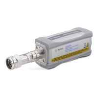
Agilent Technologies U2000 Series Manual (335 pages)
USB Power Sensors
Brand:
Agilent Technologies
| Category:
Accessories
| Size: 2.74 MB
Table of Contents
General Warranty
3
Restricted Rights Legend
3
Equipment Operation
4
General Safety Considerations
5
User Environment
5
In this Guide
6
Table of Contents
9
List of Figures
9
1 Power Sensor Remote Operation
21
Introduction
21
Configuring the Remote Interface
22
Interface Selection
22
USB Configuration
22
Zeroing and Calibrating the U2000 Series USB Power Sensors
23
Zeroing
23
Calibration
23
Table 1-1 Measure? and Configure Preset States
25
Making Measurement
25
Using Measure
26
Using the Configure Command
28
Using the Lower Level Commands
33
Using Frequency Dependent Offset Tables
35
Overview
35
Figure 1-1 Frequency Dependent Offset Tables
36
Editing Frequency Dependent Offset Tables
37
Selecting a Frequency Dependent Offset Table
40
Enabling a Frequency Dependent Offset Table
40
Making the Measurement
40
Setting the Range and Averaging
42
Averaging
42
Auto Averaging Mode
42
Figure 1-2 Typical Averaged Readings on U2000 Series USB Power Sensors
43
Figure 1-3 Averaging Range Hysteresis
43
Filter Length
44
Range
44
Setting Offsets
45
Channel Offsets
45
Figure 1-4 Limits Checking Results
46
Setting Measurement Limits
46
Setting Limits
46
Checking for Limit Failures
47
Table 1-2 Range of Values for Measurement Limits
47
Getting the Best Speed Performance
49
Measurement Rate
49
Trigger Mode
49
Output Format
51
Units
51
Command Used
51
Fast Mode
52
Figure 1-5 How Measurement Are Calculated
53
How Measurements Are Calculated
53
Status Reporting
54
The General Status Register Model
54
Figure 1-6 Generalized Status Register Model
55
Figure 1-7 Typical Status Register Bit Changes
56
How to Use Register
57
The Condition Polling Method
57
Figure 1-8 Status System
58
Table 1-3 Bit Definitions - Status Byte Register
59
Table 1-4 Bit Definitions - Standard Event Register
60
Table 1-5 Bit Definitions - Questionable Status Registers
62
Table 1-6 Bit Change Conditions for Questionable Status Register
62
Table 1-7 Bit Definitions - Operation Status
63
Table 1-8 Bit Change Conditions for Operation Status
64
Status Registers
57
Device Status Register
65
Table 1-9 Bit Definitions - Device Status Register
65
Table 1-10 Bit Change Conditions for Device Status Register
66
Using the Operation Complete Commands
67
Saving and Recalling Power Sensor Configurations
68
How to Save and Recall a Configuration
68
Using Device Clear to Halt Measurements
69
An Introduction to the SCPI Language
70
Mnemonic Forms
70
Figure 1-9 Hierarchical Structure of SCPI
70
Using a Colon (:)
70
Using "?" Commands
71
Using a Semicolon (;)
71
Using a Comma (,)
71
Using Whitespace
71
Syntax Conventions
72
Syntax Diagram Conventions
72
Using "*" Commands
72
Figure 1-10 Format of <Character_Data
73
SCPI Data Types
73
Figure 1-11 Format of <Non-Decimal Numeric
75
Figure 1-12 Format of <NR1
76
Figure 1-13 Format of <NR2
76
Figure 1-14 Format of <NR3
77
Figure 1-15 Format of <String
78
Input Message Terminators
79
SCPI Compliance Information
80
Summary of Commands
81
2 Measurement Commands
84
Figure 2-1 Measurement Display Calculate Block Window
85
Configure[1]
87
Reset Condition
88
Configure [1] Commands
89
Configure[1][:Scalar][:Power:ac] [<Expected_Value>[,<Resolution>[,<Source List>]]]
90
Fetch[1]
92
Fetch[1][:Scalar][:Power:ac]? [<Expected_Value>[,<Resolution>[,<Source List>]]]
93
Error Messages
94
READ[1] Commands
95
Read[1][:Scalar][:Power:ac]? [<Expected_Value>[,<Resolution>[,<Source List>]]]
96
Read[1][:Scalar][:Power:ac]
96
Measure[1] Commands
98
Measure[1][:Scalar][:Power:ac]? [<Expected_Value>[,<Resolution>[,<Source List>]]]
99
Figure 3-1 Measurement Display Calculate Block Window
102
Figure 3-2 Calculate Block
102
Calculate Subsystem
102
3 Calculate Subsystem
103
Calculate[1]:Feed[1]<String
104
Query Example
106
Calculate[1]:Limit Commands
107
Calculate[1]:Limit:clear:auto <Boolean>|Once
108
Calculate[1]:Limit:clear[:Immediate]
110
Calculate[1]:Limit:fail
111
Calculate[1]:Limit:fcount
112
Calculate[1]:Limit:lower[:Data] <Numeric_Value
114
Calculate[1]:Limit:upper[:Data] <Numeric_Value
116
Calculate[1]:Limit:state <Boolean
119
Calculate[1]:Math Commands
121
Calculate[1]:Math[:Expression] <String
122
Calculate[1]:Math[:Expression]:Catalog
124
4 Calibration Subsystem
126
Calibration[1][:All]
127
Calibration[1][:All]
128
Calibration[1]:Auto [ONCE|ON|OFF|0|1]
130
Calibration:zero:auto [ONCE|ON|OFF|0|1]
132
Calibration[1]:Zero:type <External|Internal
134
Calibration[1]:Zero0Ype <External|Internal
134
5 Format Subsystem
139
Format[:Readings]:Border <Character_Data
139
Format[:Readings][:Data] <Character_Data
141
6 Memory Subsystem
143
Memory Subsystem
144
Memory:catalog Commands
146
Memory Subsystem
146
Memory:catalog[:All]
147
Memory:catalog:state
149
Memory:catalog:table
150
Memory:clear Commands
152
Memory:clear[:Name] <Character_Data
153
Memory:clear[3Ame] <Character_Data
153
Memory:clear:table
155
Memory:free Commands
156
Memory:free[:All]
157
Memory:free:state
158
Memory:free:table
159
Memory:nstates
160
Memory:state Commands
161
Memory'tate Commands
161
Memory:state:catalog
162
Memory:state:define <Character_Data>,<Numeric_Value
163
Memory'tate:define <Character_Data>,<Numeric_Value
163
Memory:table Commands
165
Memory0Able Commands
165
Table 6-1 Frequency and Offset Factor List
166
Memory:table:frequency <Numeric_Value>{,<Numeric_Value
166
Memory:table:frequency:points
169
Table 6-2 Frequency and Offset Factor List
170
Memory:table:gain[:Magnitude] <Numeric_Value>{,<Numeric_Value
170
Memory:table:gain[:Magnitude]:Points
173
Memory:table:move <Character_Data>,<Character_Data
174
Memory0Able:move <Character_Data>,<Character_Data
174
Memory:table:select <Character_Data
176
Memory0Able'elect <Character_Data
176
7 Sense Subsystem
177
Sense] Subsystem
178
Sense[1]:Average Commands
180
Sense[1]:Average:count <Numeric_Value
181
Figure 7-1 Example of Averaged Readings
184
Sense[1]:Average:count:auto <Boolean
184
Sense[1]:Average:sdetect <Boolean
187
Sense[1]:Average'detect <Boolean
187
Sense[1]:Average[:State] <Boolean
189
Sense[1]:Average['Tate] <Boolean
189
Sense[1]:Correction:cset[2]Commands
191
Sense[1]:Correction:cset[2][:Select] <String
192
Sense[1]:Correction:cset[2]['Elect] <String
192
Sense[1]:Correction:cset[2]:State <Boolean
194
Sense[1]:Correction:cset[2]'Tate <Boolean
194
[Sense[1]]:Correction:dcycle|Gain3[:Input][:Magnitude] <Numeric_Value
196
[Sense[1]]:Correction:dcycle|Gain3:State <Boolean
199
Sense[1]]:Correction:dcycle|Gain3'Tate <Boolean
199
[Sense[1]]:Correction:fdoffset|Gain4[:Input][:Magnitude]
201
[Sense[1]]:Correction:gain2 Commands
202
[Sense[1]]:Correction:gain2:State <Boolean
203
Sense[1]]:Correction:gain2'Tate <Boolean
203
[Sense[1]]|Sense2:Correction:gain2[:Input] [:Magnitude] <Numeric_Value
205
Sense[1]:Detector:function <Character_Data
208
Sense[1]:Frequency[:Cw|:Fixed] <Numeric_Value
210
Sense[1]:Mrate <Character_Data
213
Sense[1]:Power:ac:range <Numeric_Value
216
Sense[1]:Power:ac:range:auto <Boolean
218
Sense[1]:Temperature
220
Table 9-1 Commands and Events Affecting Status Register
222
Status Subsystem
222
Status Register Set Commands
224
Device Status Register Sets
229
Operation Register Sets
230
Status:operation
231
Status:operation:calibrating[:Summary]
232
Status:operation:llfail[:Summary]
233
Status:operation:measuring[:Summary]
234
Status:operation:sense[:Summary]
235
Status:operation:trigger[:Summary]
236
Status:operation:ulfail[:Summary]
237
Status:preset
238
Questionable Register Sets
239
Status:questionable
240
Status:questionable:calibration[:Summary]
241
Status:questionable:power[:Summary]
242
8 Service Subsystem
245
Service:bist:trigger:level:state
248
Service Subsystem
248
Service:option <Character_Data
249
Service:sensor[1]:Cdate
250
Service:sensor[1]:Cduedate <"Date
251
Service'ensor[1]:Cduedate <"Date
251
Service:sensor[1]:Cplace <"Place
252
Service'ensor[1]:Cplace <"Place
252
Service:sensor[1]:Frequency:maximum
254
Service:sensor[1]:Frequency:minimum
255
Service:sensor[1]:Power:average:maximum
256
Service:sensor[1]:Power:usable:maximum
257
Service:sensor[1]:Power:usable:minimum
258
Service:sensor[1]:Radc
259
Service:sensor[1]:Snumber <"Serial_Number
260
Service'ensor[1]'Number <"Serial_Number
260
Service:sensor[1]:Tnumber <"Tracking_Number
261
Service'ensor[1]0Number <"Tracking_Number
261
Service:sensor[1]:Type
262
Service:snumber <Character_Data
263
Service'number <Character_Data
263
Service:version:processor <Character_Data
264
Service:version:system <Character_Data
266
Service:version'ystem <Character_Data
266
10 System Subsystem
267
System Subsystem
268
System:error
269
Figure 10-1 IEEE 488.2 Arbitrary Block Program Data Format
276
System:help:headers
276
System:preset <Character_Data
277
Table 10-1 Default: Power Sensor Presets
278
System:version
280
11 Trigger Subsystem
281
Trigger Subsystem Abort[1]
281
Trigger Subsystem
282
Initiate Commands
284
Initiate[1]:Continuous <Boolean
285
Initiate[1][:Immediate]
287
Initiate:continuous:all <Boolean
288
Initiate[1]:Continuous:sequence[1] <Boolean
290
Initiate[1]:Continuous'equence[1] <Boolean
290
Initiate[1][:Immediate]:All
292
Initiate[1][:Immediate]:Sequence[1]
293
Trigger Commands
294
Trigger[1]:Delay:auto <Boolean
295
Trigger[1][:Immediate]
297
Trigger[1]:Source Bus|External|Hold|Immediate
298
Trigger[1]'Ource Bus|External|Hold|Immediate
298
Trigger[:Sequence]:Slope <Character_Data
301
Trigger['Equence]'Lope <Character_Data
301
Trigger[:Sequence[1]]:Count <Numeric_Value
303
Trigger['Equence[1]]:Count <Numeric_Value
303
Trigger[:Sequence[1]]:Delay:auto <Boolean
305
Trigger['Equence[1]]:Delay:auto <Boolean
305
Trigger[:Sequence[1]]:Immediate
307
Trigger[:Sequence[1]]:Source Bus|External|Hold|Immediate
308
Trigger['Equence[1]]'Ource Bus|External|Hold|Immediate
308
12 UNIT Subsystem Unit[1]:Power <Amplitude_Unit
311
Figure 12-1 Measurement Display UNIT Block Window
312
Unit[1]:Power <Amplitude_Unit
313
13 IEEE 488.2 Command Reference
316
SCPI Compliance Information
316
Cls
317
Table 13-1 *ESE Mapping
318
ESE <Nrf
318
Table 13-2 *ESR? Mapping
320
Esr
320
Idn
321
Opc
322
Opt
323
RCL <Nrf
324
Rst
325
SAV <Nrf
326
Table 13-3 *SRE Mapping
327
SRE <Nrf
327
Table 13-4 *STB? Mapping
329
Stb
329
Trg
331
Tst
332
Wai
333
USBTMC/USB488 Universal Commands
334
Advertisement
Agilent Technologies U2000 Series Operating And Service Manual (101 pages)
USB Power Sensors
Brand:
Agilent Technologies
| Category:
Accessories
| Size: 3.22 MB
Table of Contents
Notices
2
Certification
3
Limitation of Warranty
3
Exclusive Remedies
3
Safety Summary
4
Safety Symbols
5
Regulatory Markings
6
Waste Electrical and Electronic Equipment (WEEE) Directive 20002/96/EC
7
General Safety Information
8
Environmental Conditions
9
Table of Contents
11
Getting Started
19
Introduction
20
Figure 3-10 Typical Power Accuracy at 25 °C for U2000/1/2/4A Models1
20
Figure 3-11 Typical Power Accuracy at 25 °C for U2000/1B Models1
20
Power Sensor Overview
21
LED Indicator Guide
22
Table 1-1 States of LED Indicator and Its Description
22
Figure 1-1 LED Indicator Sequence During Power-Up
23
Principles of Operation
24
Figure 1-2 Block Diagram of the Rf/Microwave USB Power Sensor
26
The U2000 Series USB Power Sensors in Detail
27
Figure 1-3 Simplified Block Diagram of Diode Pair/Attenuator/Diode Pair
27
Initial Inspection
29
Package Contents Checklist
29
Hardware Installation and Configuration
30
System Requirements
30
Installing Your U2000 Series USB Power Sensor
31
Figure 1-4 Found New Hardware Wizard Window
31
Figure 1-5 Found New Hardware Wizard Driver Installation
32
Figure 1-6 Hardware Installation Warning Message
32
Figure 1-7 Completing Hardware Driver Installations
33
Figure 1-8 USB Device Alias Configuration
33
Verifying Your Connected Power Sensor
34
Figure 1-9 Agilent Connection Expert with a List of Instrument I/O on the PC
34
Figure 1-10 Agilent Interactive IO Dialog Box
34
Figure 1-11 Identification of Your Connected Power Sensor Displayed
35
Configuring Your Power Sensor Via Power Analysis Manager
36
Checking the Power Sensor Firmware
37
Agilent IO Libraries Suite 15.5
37
Figure 1-12 Agilent IO Libraries Suite
37
Agilent N1918A Power Analysis Manager
38
Figure 1-13 Power Analysis Manager Instrument Properties Panel
38
Figure 1-14 Calibration Due Date Display
38
Operating Information
39
Measurement Mode
40
Average Only Mode
40
Normal Mode
40
Figure 2-1 Example of Trace Graph Display for GSM Signal
41
Figure 2-2 Measurement Gate
42
Power Sensor Configuration Settings
43
Figure 2-3 Auto-Averaging Settings
44
Measurement Accuracy and Speed
45
Setting the Range
45
Table 2-1 Sensor Ranges
45
Measurement Considerations
46
Table 2-2 Range Crossover Values
46
Internal and External Zeroing
48
Figure 2-4 Select Either INT or EXT from the Zero Type Option
49
Power Sweep and Frequency Sweep
50
Step Detection
51
Pulse Power Measurement in Average Only Mode
52
Specifications and Characteristics
53
Introduction
54
Specifications
56
Frequency and Power Ranges
56
Connector Type
56
Maximum SWR (25 °C ±10 °C)
57
SWR Plots for U2000 Series USB Power Sensors
58
Figure 3-1 U2000A Typical SWR (25 °C ±10 °C)
58
Figure 3-2 U2001A Typical SWR (25 °C ±10 °C)
59
Figure 3-3 U2002A Typical SWR (25 °C ±10 °C)
59
Figure 3-4 U2004A Typical SWR (25 °C ±10 °C)
60
Figure 3-5 U2000H Typical SWR (25 °C ±10 °C)
60
Figure 3-6 U2001H Typical SWR (25 °C ±10 °C)
61
Figure 3-7 U2002H Typical SWR (25 °C ±10 °C)
61
Figure 3-8 U2000B Typical SWR (25 °C ±10 °C)
62
Figure 3-9 U2001B Typical SWR (25 °C ±10 °C)
62
Maximum SWR (0 °C to 55 °C)
63
Maximum Power
65
Power Accuracy
66
Table 3-1 Average Only Mode Power Accuracy (with Exclusions)
66
Table 3-2 Normal Mode Power Accuracy1, (with Exclusions)
66
Figure 3-12 Typical Power Accuracy at 25 °C for U2000/1/2H Models
68
Switching Point
69
Table 3-3 Switching Point
69
Zero Set, Zero Drift, and Measurement Noise
71
Table 3-4 Noise Multiplier for Average Only Mode
73
Settling Time
77
Table 3-5 Settling Time for Normal and X2 Speed
77
Figure 3-13 Settling Time with Auto Filter, Default Resolution, and a 10 Db Decreasing Power Step (Not Across the Switching Point)
78
Calibration Factor and Reflection Coefficient
79
Cal Factor Uncertainty
80
Trigger
83
Normal Mode Key Specifications and Characteristics
84
General Characteristics
85
Service
87
General Information
88
Cleaning
88
Connector Cleaning
88
Performance Test
89
Standing Wave Ratio (SWR) and Reflection Coefficient (Rho) Performance Test
89
Table 4-1 Power Sensor SWR and Reflection Coefficient for the U2000A
89
Table 4-2 Power Sensor SWR and Reflection Coefficient for the U2001A
89
Table 4-3 Power Sensor SWR and Reflection Coefficient for the U2002A
90
Table 4-4 Power Sensor SWR and Reflection Coefficient for the U2004A
90
Table 4-5 Power Sensor SWR and Reflection Coefficient for the U2000H
90
Table 4-6 Power Sensor SWR and Reflection Coefficient for the U2001H
91
Table 4-7 Power Sensor SWR and Reflection Coefficient for the U2002H
91
Table 4-8 Power Sensor SWR and Reflection Coefficient for the U2000B
91
Table 4-9 Power Sensor SWR and Reflection Coefficient for the U2001B
91
Replaceable Parts
92
Table 4-10 Replaceable Parts
93
Service
94
Troubleshooting
94
Repairing a Defective Sensor
94
Disassembly and Reassembly Procedure
95
Table 4-11 Disassembly Procedure
95
Attenuator Disassembly and Reassembly Procedure for U2000B and U2001B
97
Table 4-12 Attenuator Disassembly Procedure
97
Table 4-13 Attenuator Reassembly Procedure
98
Appendix
99
Appendix A: Zero Set, Zero Drift, and Measurement Noise
100
Table 5-1 Zero Set, Zero Drift, and Measurement Noise for Average Only Mode
100
Advertisement
Related Products
Agilent Technologies U2000H
Agilent Technologies U2001B
Agilent Technologies U2002H
Agilent Technologies U2000A
Agilent Technologies U2781A
Agilent Technologies U2741A
Agilent Technologies U2701A
Agilent U2331A
Agilent Technologies U2600A Series
Agilent Technologies U2300A Series
Agilent Technologies Categories
Measuring Instruments
Laboratory Equipment
Test Equipment
Water Pump
Power Supply
More Agilent Technologies Manuals
Login
Sign In
OR
Sign in with Facebook
Sign in with Google
Upload manual
Upload from disk
Upload from URL