AudioCodes Mediant 1000 User Manual
Voip mediant digital media gateways megaco, tpncp
Hide thumbs
Also See for Mediant 1000:
- User manual (1195 pages) ,
- Hardware installation manual (84 pages) ,
- Installation manual (76 pages)

Related Manuals for AudioCodes Mediant 1000


Summary of Contents for AudioCodes Mediant 1000
- Page 1 ™ VoIP Mediant Digital Media Gateways Mediant 1000 MEGACO, TPNCP User’s Manual 4.6 Document # LTRT-66401 August 2005...
-
Page 3: Table Of Contents
Mounting the Mediant 1000 ..................38 3.1.3.1 Mounting the Mediant 1000 on a Desktop ..........38 3.1.3.2 Installing the Mediant 1000 in a 19-inch Rack ........38 3.1.4 Cabling the Mediant 1000..................39 3.1.4.1 Connecting the Mediant 1000 RS-232 Port to Your PC......40 3.1.4.2... - Page 4 Digital Mediant 1000 Restoring Networking Parameters to their Initial State .......... 49 Mediant 1000 Initialization & Configuration Files ...........51 Boot Firmware & Operational Firmware..............51 Mediant 1000 Startup..................... 51 Using BootP/DHCP ....................53 6.3.1 BootP/DHCP Server Parameters ................54 6.3.2 Host Name Support ....................56 6.3.3...
- Page 5 Termination Name Patterns ..............109 7.2.6.2 Old Termination Naming Method ............109 7.2.6.3 Backward Compatibility ................. 110 7.2.6.4 Termination Mapping to a PSTN Interface..........110 Mediant 1000 Management................117 Using SNMP......................117 8.1.1 About SNMP ......................117 8.1.1.1 SNMP Message Standard..............117 8.1.1.2 SNMP MIB Objects ................
- Page 6 Limiting Web Access to a Predefined List of Client IP Addresses..136 8.3.2.5 Managing Web Server Access Using a RADIUS Server ...... 136 8.3.3 Correlating PC / Mediant 1000 IP Address & Subnet Mask ......... 136 8.3.4 Accessing the Embedded Web Server..............137 8.3.5 Using Internet Explorer to Access the Embedded Web Server......
- Page 7 9.5.1 Possible Common Problems ................191 9.5.2 Possible Voice Problems ..................193 10 Functional Specifications................195 10.1 Mediant 1000 Selected Technical Specifications..........195 11 Appendix - BootP/TFTP Server ..............197 11.1 Introduction ......................197 11.1.1 Key Features ......................197 11.1.2 Specifications......................198 11.1.3 BootP/TFTP Server Installation ................
- Page 8 Digital Mediant 1000 13 Appendix - RTP/RTCP Payload Types............259 13.1 Payload Types Defined in RFC 3551..............259 13.2 Payload Types ..................... 260 13.3 Payload Types Not Defined in RFC 3551 ............260 13.4 Default Dynamic Payload Types Which are Not Voice Coders......261 13.5 Default RTP/RTCP/T.38 Port Allocation ..............
- Page 9 19.1 Basic Setup ......................317 19.2 Setup Example..................... 317 19.3 Preparing the Mediant 1000 for VLANs and Multiple IPs (MI) ......317 19.4 Verifying the VLANS and Multiple IP settings using the Embedded Web Server 320 19.5 OAM Parameters ....................321 19.6 MI and VLAN Parameters ..................
- Page 10 Digital Mediant 1000 21.5 Modifying ini File Parameters via the Web Interface's AdminPage...... 340 22 Appendix - Regulatory Information ...............343 23 List of Abbreviations..................347 Index ........................351 User's Manual Document # LTRT-66401...
- Page 11 Contents List of Figures Figure 1-1: Typical Mediant 1000 Wireline Application ................23 Figure 2-1: Mediant 1000 Front View & CPU Enlargement ..............25 Figure 2-2: Mediant 1000 Front Layout ....................26 Figure 2-3: Location of Front Panel LEDs ....................28 Figure 2-4: Slightly Extracted Fan Try Unit ....................30 Figure 2-5: Fan Try with Filter Extracted ....................30...
- Page 12 Digital Mediant 1000 Figure 8-36: Transport Settings Screen ....................174 Figure 8-37: Voice Settings Screen..................... 175 Figure 8-38: IBS Detector Settings Screen ..................175 Figure 8-39: Jitter Buffer Settings Screen ................... 175 Figure 8-40: Message Log Screen ...................... 176 Figure 8-41: Versions Screen......................177 Figure 8-42: Start Software Upgrade Screen ..................
- Page 13 List of Tables Table 2-1: Mediant 1000 Front View Component Descriptions..............26 Table 2-2: Functionality of the Front Panel LEDs ..................28 Table 2-3: Mediant 1000 Rear Connectors Component Descriptions ...........31 Table 2-4: Extractable Mediant 1000 Modules..................32 Table 2-5: CM Module Component Descriptions ...................33 Table 2-6: iPMX Module Component Descriptions ................34...
- Page 14 Digital Mediant 1000 Table 12-4: Infrastructure Parameters ....................230 Table 12-5: Common Control Parameters ..................238 Table 12-6: MEGACO Specific Parameters ..................244 Table 12-7: Web Parameters ......................247 Table 12-8: SNMP Parameters ......................252 Table 12-9: SCTP Parameters ......................255 Table 12-10: Default RTP/RTCP/T.38 Port Allocation ................
- Page 15 User's Manual Contents Reader’s Notes Version 4.6 August 2005...
-
Page 17: Introductory Matter
Notice This User’s Manual describes the installation and use of the Mediant 1000. Information contained in this document is believed to be accurate and reliable at the time of printing. However, due to ongoing product improvements and revisions, AudioCodes cannot guarantee the accuracy of printed material after the Date Published nor can it accept responsibility for errors or omissions. -
Page 18: Related Documentation
The documentation package contains the following four publications available on the AudioCodes Web site: Digital Mediant 1000 User's Manual (this manual) - contains the boards’ physical description, installation instructions, standard control protocols and management protocols description and general features of the board which are not control protocol specific (for example various networking issues). -
Page 19: Overview Of The Mediant 1000
PBX systems to IP networks, as well as seamless connection of the IP-PBX to the PSTN. In addition to operating as a pure media gateway, the Mediant 1000 can also host partner applications and serve as an IP-PBX platform. The Mediant 1000 is fully interoperable with multiple vendor gateways, Softswitches, gatekeepers, proxy servers, IP phones, session border controllers and firewalls. -
Page 20: General Features
Digital Mediant 1000 General Features The Mediant 1000 has the following features for wireless applications: Vocoder configuration options: • PCM/ADPCM, G.711, G.723, G.723.1, G.729A, GSM-FR and NetCoder Up to 4 E1/T1 digital spans Independent vocoder selection per channel Extensive media processing functions RTP stream multiple destination connection (i.e., to TDM, other RTP channels) -
Page 21: Supported Protocols
User's Manual 1. Overview of the Mediant 1000 Mounting option of installing two Mediant 1000 Gateways in a single 19-inch rack shelf, 1 U high (1.75" or 44.5 mm) Optional dual redundant AC power supplies 1.1.1 Supported Protocols The Mediant 1000 software supports the following Protocols: 1.1.1.1... -
Page 22: Mediant 1000 Applications
Digital Mediant 1000 Mediant 1000 Applications The Mediant 1000 can be used in a variety of applications, which exploit its unique advantages regarding compressing PCM voice channels to IP packets according to ITU and IETF standards. Examples include: PBX Networking IP-Centrex/Hosted IP-PBX Partner Applications (e.g., IP-PBX, Call Center) Applications... -
Page 23: Typical Application Diagram
User's Manual 1. Overview of the Mediant 1000 Typical Application Diagram The diagram below illustrates a typical wireline application. Figure 1-1: Typical Mediant 1000 Wireline Application Version 4.6 August 2005... -
Page 25: Hardware Equipment
19-inch industrial platform chassis, 1U high and 13.8 inch deep. The Mediant 1000 supports a scalable, modular architecture that includes up to four digital modules, a single CPU module, a power supply module and an optional fan try module (the... -
Page 26: I/O Modules
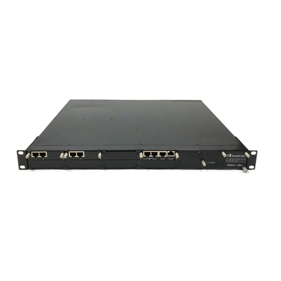
Locking Screw (2). Figure 2-2 illustrates the front layout of the Mediant 1000. There is also a schematic of the front layout on the front panel of the fan tray. To view your specific device’s configuration use the Embedded Web Server... -
Page 27: Power Supply Module (Labeled 1 And 2)
DB-9 adaptor cable is supplied. 2.1.1.2.5 Reset Button (Labeled //) The Mediant 1000 Reset button, indicated by the ‘//’ symbol, is located directly above the RS-232 port. To reset the system, take a pointed object and press in the Reset button. -
Page 28: Front Panel Leds
Digital Mediant 1000 The front panel of the power supply unit features a power supply LED that is lit green when the Mediant 1000 is powered up. If this LED does not light up, a power supply problem may be present. -
Page 29: Fan Tray Module (Optional)
RF interference. The clean air passes through the entire set of modules cooling each one and exits the Mediant 1000 via perforated vents on the left side of the chassis. Blank panels are used to cover all unoccupied slots on the front and rear sides of the chassis. -
Page 30: Figure 2-4: Slightly Extracted Fan Try Unit
If you are cleaning the filter, use a vacuum cleaner (on light suction) to remove dust particles from the filter. Alternatively, if you are replacing the filter, discard the old air filter and replace it with an air filter purchased from AudioCodes. User's Manual Document # LTRT-66401... -
Page 31: Mediant 1000 Rear Panel
2.1.2 Mediant 1000 Rear Panel The Mediant 1000 rear connectors are described in the following sections (refer to Figure 2-6). Figure 2-6: Mediant 1000 Rear Connectors Table 2-3: Mediant 1000 Rear Connectors Component Descriptions... -
Page 32: Mediant 1000 Modules
Digital Mediant 1000 2.1.3 Mediant 1000 Modules The extractable Mediant 1000 modules are shown in Table 2-4 below. Table 2-4: Extractable Mediant 1000 Modules Module Description CPU module Digital I/O module Fan tray module with 6 fans Power supply module... -
Page 33: Partner Application Platform
The Mediant 1000 can also host a flexible platform for partner applications. The open platform on the Mediant 1000 offers partners the option to host their own applications (e.g., IP-PBX or call center application) using a powerful, low-power consumption processor and hard disks to provide a complete solution within the Mediant 1000 chassis 2.1.4.1... -
Page 34: Figure 2-8: Ipmx Module
Digital Mediant 1000 The iPMX module includes a backup battery that is responsible for Note: retaining the CMOS setup configuration. The battery lasts for 18 months of non-operating conditions. When empty (the CMOS configuration returns to its default). Replace with Lithium battery model CR-1225. -
Page 35: Hdmx Module
Audio out Audio out Relay 2.1.4.3 HDMX Module The HDMX module is located on the Mediant 1000 rear panel. A 40 Giga Byte Hard Disk Drive 5200 RPM. A second HDD is optional. Figure 2-11: HDMX Module HDD activity Version 4.6... - Page 36 Digital Mediant 1000 Reader’s Notes User's Manual Document # LTRT-66401...
-
Page 37: Installation
3.1.4 on page 39). After connecting the Mediant 1000 to the power source, the power LED on the front panel of the power supply unit is lit green (after a self-testing period of about 2 minutes). Any power supply malfunction results in the LED switching off (refer to... -
Page 38: Mounting The Mediant 1000
Installing the Mediant 1000 in a 19-inch Rack Users can install the Mediant 1000 in a standard 19-inch rack either by placing it on a shelf preinstalled in the rack (preferred method), or by attaching it directly to the rack’s frame. If the rack is without shelves, it is advised to acquire shelves. -
Page 39: Cabling The Mediant 1000
For the connector’s pinout, refer to Figure 3-2 on page 40. When assigning an IP address to the Mediant 1000 using HTTP (under Step xxx in Section xxx), you may be required to disconnect this cable and re-cable it differently. -
Page 40: Connecting The Mediant 1000 Rs-232 Port To Your Pc
3 - Rx+ connected 6 - Rx- 3.1.4.1 Connecting the Mediant 1000 RS-232 Port to Your PC Using the supplied RS-232 cable (shown in Figure 3-3) connect the Mediant 1000 RS-232 port (Labeled I0I0) to either COM1 or COM2 RS-232 communication port on your PC. -
Page 41: Figure 3-4: Dry Contact Wires' Mate
User's Manual 3. Installation Figure 3-4: Dry Contact Wires’ Mate Table 3-1: Dry Contact Wires’ Mate Component Descriptions Item # Component Description Position 1 4 spring-cage connections Orange Buttons: Press to open spring-cage connections Position 4 The mate features four spring-cage connections: Positions 4, 3, 2 and 1 (from left to right) correspond to the four pins in the connector on the CPU module’s front panel. -
Page 42: Connecting The Audio In/Out Cable
The audio IN level must be below the AC signal 2V PTP (peak-to- Audio IN Level peak). Audio OUT Level The audio OUT level is variable but must not exceed 3V PTP. Figure 3-5: Audio Cable and IN/OUT RCA Connectors Not currently supported. Contact AudioCodes regarding availability. User's Manual Document # LTRT-66401... -
Page 43: Software Package
Check the software package contents (go to ''Software Directory Contents & Structure'' on page 44.) To configure the Mediant 1000's IP address, go to ''Getting Started'' on page 47. Unzipping the Software Package The software package is contained on a CD supplied with the device. It is also available on the AudioCodes' FTP Web site. -
Page 44: Software Directory Contents & Structure
PCI Diagnostic Utility – a utility for .\Utilities\PCI_Diagnostic_Utility diagnostics of AudioCodes PCI boards. PSTN Trace Utility – a utility for .\Utilities\PSTN_Trace_Utility analyzing a trace of PSTN signaling events recorded by an AudioCodes device. Special ID Utility - TBD .\Utilities\SpecialID_Utility User's Manual Document # LTRT-66401... - Page 45 User's Manual 4. Software Package Table 4-1: Software Package Contents Contents Directory Description AudioCodes’ proprietary API for VoP API Library controlling and managing the device. Detailed information on the VoPLibrary can be found in AudioCodes’ VoPLib API Reference Manual, Document #: LTRT-840xx and VoPLib User’s Manual,...
- Page 46 Digital Mediant 1000 Reader’s Notes User's Manual Document # LTRT-66401...
-
Page 47: Getting Started
(with factory default parameters). The Mediant 1000 is also supplied with an Embedded (integrally stored) Web Server. Assigning the Mediant 1000 IP Address below describes how to assign an IP address to the Mediant 1000. 'Restoring Networking Parameters to their Initial State' on page describes how to restore the network parameters to their initial state. -
Page 48: Assigning An Ip Address Using Bootp
BootP/TFTP configuration utility to access the device). Disconnect your PC from the Mediant 1000 or from the hub / switch (depending on the connection method you used in step 1 above). Reconnect the Mediant 1000 and your PC (if necessary) to the LAN. -
Page 49: Restoring Networking Parameters To Their Initial State
User's Manual 5. Getting Started Restoring Networking Parameters to their Initial State You can use the Reset button to restore the networking parameters to their factory default values (described in the "Default Networking Parameters" above) and to reset the username and password. Note that this process also restores the parameters to their factory settings, therefore you must load your previously backed-up ini file, or the default ini file (received with the software kit) to set them to their correct values. - Page 50 Digital Mediant 1000 Reader’s Notes User's Manual Document # LTRT-66401...
-
Page 51: Mediant 1000 Initialization & Configuration Files
1000. These files contain the Mediant 1000's main software, providing all the services described in this manual. The cmp file is usually burned into the Mediant 1000's non- volatile memory so that it does not need to be externally loaded each time the Mediant 1000 is reset (except when the board is controlled via PCI). -
Page 52: Figure 6-1: Startup Process Diagram
Digital Mediant 1000 Users perform a reset in the Embedded Web Server GUI or SNMP manager. The flow chart in the figure below illustrates the process that occurs in scenarios 1-5. Figure 6-1: Startup Process Diagram Reset board via Power... -
Page 53: Using Bootp/Dhcp
Using BootP/DHCP The Mediant 1000 uses BootP (Bootstrap protocol) and DHCP to configure the Mediant 1000's initial parameters. BootP/DHCP enables network administrators to manage the basic configuration of the Mediant 1000 from a central server. -
Page 54: Bootp/Dhcp Server Parameters
Mediant 1000 every time a BootP/DHCP process takes place. Default Gateway IP address - This configuration parameter is optional. The default Gateway IP address is supplied to the Mediant 1000 by BootP/DHCP only if the field is defined/configured in the server. -
Page 55: Table 6-1: Command Line Switch Descriptions
Mediant 1000. The switch only takes effect from the next reset of the Mediant 1000. Selective BootP Use -be 1 for the Mediant 1000 to send client information that can be viewed in the main screen of the BootP/TFTP Server, under column 'Client Info‘ (refer to the figure, 'Main Screen' on page 201, with the column 'Client Info' on the extreme right). -
Page 56: Host Name Support
Mediant 1000's integral non-volatile memory. Whenever the Mediant 1000 is reset and no BootP reply is sent to the board or the ini file name is missing in the BootP reply, the Mediant 1000 uses the previously stored ini file. -
Page 57: Table 6-2: Vendor Specific Information Field Tags
User's Manual 6. Mediant 1000 Initialization & Configuration Files The table below details the Vendor Specific Information field according to the Mediant 1000: Table 6-2: Vendor Specific Information Field Tags Tag # Description Value Length Board Type Current IP Address XXX.XXX.XXX.XXX... -
Page 58: Microsoft™ Dhcp/Bootp Server
The reservation builds an association between MAC address (12 digits), provided in accompanying product documentation) and the IP address. Windows™ NT Server provides the IP address based on the Mediant 1000 MAC address in the BootP request frame. To configure the Microsoft™ Windows™ NT DHCP server to provide Boot File information to BootP clients, edit the BootP Table in the DHCP Manager. -
Page 59: Initialization (Ini) File
There in no need to repeatedly reload the modified files after reset. Users who configure the Mediant 1000 with the Embedded Web Server do Note 1: not require downloading the ini file and have no need to utilize a TFTP server. -
Page 60: Parameter Value Construct
Digital Mediant 1000 6.4.1.1 Parameter Value Construct The following are the rules in the ini File Structure for individual ini file parameters (Parameter = Value): Lines beginning with a semi-colon ';' (as the first character) are ignored. An Enter must be the final character of each line. - Page 61 ; This parameter defines the profile used. 1 - is for version 2, 2 - for version 1 MGCPCOMPATIBILITYPROFILE = 2 Before loading an ini file to the Mediant 1000, make sure that the extension Note: of the ini file saved on your PC is correct: Verify that the checkbox Hide extension for known file types (My Computer>Tools>Folder Options>View)
-
Page 62: Tables Of Parameter Value Construct
The tables below provide useful examples for reference. The tables below are provided as examples for the purpose of illustration Note: only and are NOT actually implemented in Mediant 1000. Table 6-4: Table of Parameter Values Example - Remote Management Connections Index Fields: 1. -
Page 63: Rules In The Ini File Structure For The Tables Of Parameter Value Construct
User's Manual 6. Mediant 1000 Initialization & Configuration Files 6.4.1.3.1 Table Indices Each row in a table must be unique. For this reason, each table defines one or more Index fields. The combination of the Index fields determines the 'line-tag'. Each line-tag may appear only once. - Page 64 Digital Mediant 1000 6.4.1.4.1 Tables Structure Rules Tables are composed of four elements: Table-Title - The Table's string name in square brackets (e.g., [ MY_TABLE_NAME ]). Format Line - This line specifies the table's fields by their string names. •...
- Page 65 User's Manual 6. Mediant 1000 Initialization & Configuration Files A line in a table is identified by its table-name and its indices. Each such line may appear only once in the ini file. Table's dependencies: Certain tables may depend on other tables. For example, one table may include a field, which specifies an entry in another table, to specify additional attributes of an entity, or to specify that a given entity is part of a larger entity.
-
Page 66: Secured Configuration File Download
Mediant 1000, it is also retrieved encoded from the Mediant 1000 as well. When a decoded file is downloaded to the Mediant 1000, it is also retrieved decoded from the Mediant 1000 as well. -
Page 67: Auxiliary Files
[AuxilaryFileType]FileName. This parameter takes the name of the auxiliary file to be downloaded to the Mediant 1000. If the ini file does not contain a parameter for a specific auxiliary file type, the Mediant 1000 uses the last auxiliary file that was stored on the non- volatile memory. -
Page 68: Call Progress Tone And User-Defined Tone Auxiliary Files
AudioCodes can be used to construct your own file. The Call Progress Tones and User-Defined Tones file used by the Mediant 1000 is a binary file with the extension tone.dat. Only this binary tone.dat file can be loaded to a Mediant 1000. - Page 69 User's Manual 6. Mediant 1000 Initialization & Configuration Files Ringback Tone Busy Tone Congestion Tone Warning Tone Reorder Tone Confirmation Tone Call Waiting Tone For a full tone indices list, refer to enum definition in the “VoPLib API Reference Manual”, Document #: LTRT-840xx.
- Page 70 Digital Mediant 1000 Fourth Signal On Time [10 msec] - “Signal On” period (in 10 msec units) for the fourth cadence ON-OFF cycle. This may be omitted if there is no fourth cadence. Fourth Signal Off Time [10 msec] - “Signal Off” period (in 10 msec units) for the fourth cadence ON-OFF cycle.
- Page 71 6.4.2.2.3 Default Template for Call Progress Tones The Mediant 1000 is initialized with the default Call Progress Tones configuration. To change one of the tones, edit the default call progress txt file. The table below lists the default call progress tones.
-
Page 72: Table 6-6: Default Call Progress Tones
Digital Mediant 1000 Table 6-6: Default Call Progress Tones [NUMBER OF CALL PROGRESS TONES] Number of Call Progress Tones=9 #Dial tone Tone Type=1 [CALL PROGRESS TONE #0] Tone Form = 1 (Continuous) Low Freq [Hz]=350 High Freq [Hz]=440 Low Freq Level [-dBm]=13 (-13dBm) - Page 73 User's Manual 6. Mediant 1000 Initialization & Configuration Files Table 6-6: Default Call Progress Tones [NUMBER OF CALL PROGRESS TONES] Number of Call Progress Tones=9 #Busy Tone Type=3 [CALL PROGRESS TONE #4] Tone Form = 2 (Cadence) Low Freq [Hz]=480...
- Page 74 Call Progress Tone dat binary file in the software package under Auxiliary_Files\Sample_Call_Progress_Files\. Only the binary dat file can be sent to the Mediant 1000. In the auxiliary source file, customers can modify Call Progress Tone levels, Call Progress Tone frequencies to be detected/generated by the Mediant 1000, to suit customer-specific requirements.
-
Page 75: Playing Prerecorded Tones (Prt)
After modifying the original CPT ini file (supplied with the Mediant 1000's software package), you can use the Download Conversion Utility to convert the modified file into a dat binary file. You can send only the dat file to the Mediant 1000; the ini file cannot be sent. -
Page 76: Automatic Update Facility
The maximum number of prerecorded tones that can be stored in one dat Note: file is 40. 6.4.2.3.2 Downloading the PRT dat File Downloading the PRT dat file into the Mediant 1000 can be done using one of the following: HTTP TFTP VoPLib API For HTTP and TFTP download, refer to ''Software Upgrade Wizard'' on page 178. - Page 77 To update the firmware image using the Automatic Update facility, use the CMPFILEURL parameter to point to the image file. As a precaution (in order to protect the Mediant 1000 from an accidental update), you must also set AUTOUPDATECMPFILE to 1.
-
Page 78: Backup Copies Of Ini And Auxiliary Files
RESETNOW = 1 You may modify the master_configuration.ini file (or any of the config_<MAC>.ini files) at any time. The Mediant 1000 queries for the latest version every 60 minutes, and applies the new settings immediately. Backup Copies of ini and Auxiliary Files Be sure to separately store a copy of the ini file and all auxiliary files, as well as a note of the software version for use should a board require replacement. -
Page 79: Standard Control Protocols
Mediant 1000 and handled by an external Media Gateway Controller (MGC). MEGACO is a master/slave protocol, where the Mediant 1000 is expected to execute commands sent by the Call Agent (another name for MGC). -
Page 80: Keepalive Notifications From The Gateway
The first Call Agent in the list is the primary one. In the case of a loss of connection, the Mediant 1000 tries to connect with the next on the list, and it continues trying until one of the Call Agents accepts the registration request. If the current connection is with a secondary MGC, the Mediant 1000 starts again from the primary MGC. -
Page 81: Authorization Check Of Call Manager Ip Addresses
Authorization Check of Call Manager IP Addresses While the MEGACO specification specifies that only one Call Manager can send commands to the gateway at a time, AudioCodes gateways handle the Authorization Check in either of these modes: No authorization check is performed. This mode specifies that every command is accepted and executed. -
Page 82: Mediation
CPT file IDs, refer to the column, Map to CPT File of the table, ''Generic Media Package - G''. When a CPT file is missing, the Mediant 1000 defines default values only for the following signals: Dial tone... -
Page 83: Cas/R2 Support In Megaco
H.248.25, the 'icas' and 'casblk' packages defined in H.248.28 and 'icasc' package defined in H.248.29 Using these packages, the Mediant 1000 converts from the MFC-R2 protocol, which is a PSTN protocol, to the MEGACO protocol, thereby bridging the PSTN world with the IP world. - Page 84 Digital Mediant 1000 When MEGACO and MFC-R2 protocols share control of a channel, their timings are synchronized so that MEGACO commands do not cause damage to the MFC-R2 protocol's negotiation. For example, MFC-R2 protocol must work with the Echo Canceler in OFF state or else Multiple Frequency (MF) is not received correctly.
-
Page 85: Figure 7-1: Megaco-R2 Call Start Flow Diagram
User's Manual 7. Standard Control Protocols Blocking the Bchannel is done by using the 'casblk' package. The 'blk' and 'ublk' events are reported only if the action was done by the remote side. The reason for this is that the local side already knows its status. -
Page 86: Rfc 2833 Support
Digital Mediant 1000 Figure 7-2: MEGACO-R2 Call Disconnect Flow Diagram Terminator Disconnects MFCR2 H.248 H.248 MFCR2 Outgoing MG Incoming MG Clear back NOTIFY(OE=77{icas/cb}) Wait for Disconnect timer MODIFY(SG{icas/cb}, E=88{icas/cf}) Clear back Clear forward NOTIFY(OE=88{icas/cf}) MODIFY(SG{ibcas/cf}, E=99{icas/rlg}) Clear forward Release guard... -
Page 87: Silence Suppression Support
(any number from the dynamic range can be used). Negotiation is performed according to the following rules: If the remote side does not specify the 'telephone-event' in the SDP, the Mediant 1000 uses the default value as the transport type. -
Page 88: Fax T.38 And Voice Band Data Support (Bypass Mode)
7.2.2.12 Fax T.38 and Voice Band Data Support (Bypass Mode) Previous loads supported T.38 without MEGACO interference, if the Mediant 1000 was configured to support T.38: FaxTransportType should be configured to T.38 Relay. Fax redundancy can be controlled using the configuration parameter FaxRelayRedundancyDepth. -
Page 89: Digits Collection Support
'm=image' line, however, is mandatory, and should appear in the identical format to the above. The Mediant 1000 returns a fully specified line with the local port used for the T.38. Fax redundancy can be requested by including the following attribute line after the... -
Page 90: Reporting Fax Events
Digital Mediant 1000 7.2.2.14 Reporting Fax Events Some of the Fax events can be reported using the packages from H.248.2: "CTYP" and "IPFAX". The only Fax events reported by the "CTYP" package are the "V21flag" and “cng”, using the "ctyp/dtone" event. -
Page 91: Mapping Payload Numbers To Coders
The table below shows the default mapping between payload numbers and coders when the dynamic payload assignment is not used. Note that this is a general table and only the DSP template that is loaded to a Mediant 1000 defines which coder is supported on this Mediant 1000. -
Page 92: Table 7-2: Megaco Mapping Payload Numbers To Coders
Digital Mediant 1000 Table 7-2: MEGACO Mapping Payload Numbers to Coders Default Payload Encoding Name Coder Number “PCMU” G711Mulaw "G726-32" G726_32 "GSM" “GSM-EFR” GSM-EFR "G723" G723 (High) "G723" G723 (Low) "PCMA" G711Alaw_64 "G728" G728 "G729" G729 "G726-16" G726_16 "G726-24" G726_24 "G726-40"... - Page 93 Redundancy per RFC 2198 “CN” Comfort Noise When using dynamic payloads, do not use the Mediant 1000 default Note: payloads for RFC 2833 (96) and RFC 2198 (104). If these values must be used, the default values for the two RFCs should be changed in the ini file.
-
Page 94: Supported Megaco Packages
Digital Mediant 1000 7.2.4 Supported MEGACO Packages Events, signals, properties and statistics are grouped in packages. A package can be extended by a new package. In this case, the basic package becomes a part of the new package. The TrunkPack series MEGACO protocol supports the basic set of packages as defined in Annex E of RFC 3015 (Refer to the document at www.letf.org/rfc/, 'RFC Index'.), according... -
Page 95: Base Root Package - Root
User's Manual 7. Standard Control Protocols 7.2.4.2 Base Root Package - ROOT Table 7-4: Base Root Package - ROOT Symbol Definition Type maxNumberOfContexts Maximum number of Contexts in the Property device maxTerminationsPerContext Maximum Terminations in a Context Property normalMGExecutionTime Timer for Retransmission Property normalMGCExecutionTime Timer for Retransmission... -
Page 96: Dtmf Generator Package - Dg (Extends Tonegen)
Digital Mediant 1000 7.2.4.5 DTMF Generator Package - DG (Extends ToneGen) Table 7-7: DTMF Generator Package - DG Symbol Definition Type Duration DTMF 0 Signal DTMF 1 Signal DTMF 2 Signal DTMF 3 Signal DTMF 4 Signal DTMF 5 Signal... -
Page 97: Dtmf Detection Package - Dd (Extends Tonedet)
User's Manual 7. Standard Control Protocols 7.2.4.6 DTMF Detection Package - DD (Extends ToneDet) Table 7-8: DTMF Detection Package - DD Symbol Definition Type DigitMap Completion Event Event DTMF 0 Event DTMF 1 Event DTMF 2 Event DTMF 3 Event DTMF 4 Event DTMF 5... -
Page 98: Call Progress Tones Generator Package - Cg (Extends Tonegen)
Digital Mediant 1000 7.2.4.7 Call Progress Tones Generator Package - CG (Extends ToneGen) Table 7-9: Call Progress Tones Generator Package - CG Symbol Definition Type Duration Map to CPT File Dial tone Signal 180 sec Ringing tone Signal 180 sec... -
Page 99: Basic Continuity Package - Ct
User's Manual 7. Standard Control Protocols 7.2.4.9 Basic Continuity Package - CT Table 7-11: Basic Continuity Package - CT Symbol Definition Type Duration Map to CPT file Detects test completion Event Initiates sending the Signal 2 sec User Defined tone Responds to continuity Signal 2 sec... -
Page 100: Network Package - Nt
Digital Mediant 1000 7.2.4.10 Network Package - NT Table 7-12: Network Package - NT Symbol Definition Type Maximal jitter buffer size Property netfail Network failure Event qualert Quality alert - Not supported Event Termination's InContext duration Statistics Octets sent Statistics... -
Page 101: Generic Announcement Package - An
User's Manual 7. Standard Control Protocols 7.2.4.13 Generic Announcement Package - AN Table 7-15: Generic Announcement Package Symbol Definition Type Supported Parameters Initiates the play of a fixed Signal An - Announcement number announcement Di - The direction of the announcement Noc - Number of cycles Initiates the play of a Signal... -
Page 102: Basic Service Tones Generation Package - Srvtn (Extends - Tonegen)
Digital Mediant 1000 7.2.4.15 Basic Service Tones Generation Package - SRVTN (Extends - ToneGen) Table 7-17: Basic Service Tones Generation Package - SRVTN Symbol Definition Type Duration Map to CPT File Recall dial tone Signal 180 sec conf Confirmation tone... -
Page 103: Basic Cas Package - Bcas
User's Manual 7. Standard Control Protocols 7.2.4.17 Basic CAS Package - BCAS Table 7-19: Basic CAS Signal/Events Symbol Definition Type Duration Map to CPT File Symbol Seizure Signal/Event None Seizure ack Signal/Event None Answer Signal/Event None idle idle Signal/Event None casf CAS failure Event... -
Page 104: International Cas Package - Icas (Extends - Bcas)
Digital Mediant 1000 7.2.4.18 International CAS Package – ICAS (Extends – BCAS) Table 7-20: International CAS Signal/Events Symbol Definition Type Duration Map to CPT File Symbol Subscriber Signal/Event None line status Clear forward Signal/Event None Clear back Signal/Event None casf... -
Page 105: Mf Generator Package - Mfg (Extends - Tonegen)
User's Manual 7. Standard Control Protocols 7.2.4.21 MF Generator Package - MFG (Extends - ToneGen) Table 7-23: MF Generator Package - MFG Symbol Definition Type Duration MF 0 Signal MF 1 Signal MF 2 Signal MF 3 Signal MF 4 Signal MF 5 Signal... -
Page 106: Mf Detection Package - Mfd (Extends - Tonedet)
Digital Mediant 1000 7.2.4.22 MF Detection Package - MFD (Extends - ToneDet) Table 7-24: MF Generator Package - MFG Symbol Definition Type MF 0 Event mf 1 MF 1 Event mf 2 MF 2 Event mf 3 MF 3 Event... -
Page 107: Basic Call Progress Tones Generator With Directionality Package - Bcg
User's Manual 7. Standard Control Protocols 7.2.4.24 Basic Call Progress Tones Generator with Directionality Package - BCG (Extends ToneGen) Table 7-26: Basic Call Progress Tones Generator with Directionality Package - BCG Map to CPT Symbol Definition Type Duration File Dial tone Signal 180 sec Ringing tone... -
Page 108: Ip Fax Package - Ipfax
Bit 4 (Value 16) - Enables the following features: • In the serviceChange request, the Timestamp parameter is omitted. • The audit command on ROOT termination with packages descriptor returns the total supported packages for the Mediant 1000. User's Manual Document # LTRT-66401... -
Page 109: Megaco Termination Naming
- 'RTP/' for RTP terminations and 'ATM/' for ATM terminations. So assuming that the Mediant 1000 name is 'gw', if the first ephemeral Termination is of RTP type, it is called 'gwRTP/1', and if it is of ATM type, it is called 'gwATM/1'. -
Page 110: Backward Compatibility
PSTN Interface - mapping Trunk/B-channel pairs to Endpoints is hardware-specific (refer to the table, ''MEGACO EndPoint Names'' on page 112.) Note that the number of supported terminations per Mediant 1000 is equal to the channel density of the Mediant 1000. - Page 111 User's Manual 7. Standard Control Protocols The table below lists only the names for a two trunks unit. Version 4.6 August 2005...
-
Page 112: Table 7-31: Megaco Endpoint Names
Digital Mediant 1000 Table 7-31: MEGACO Endpoint Names T1/J1 - CAS E1 - PRI/CAS E1 - T1/J1 - Endpoint Name E1 - Transparent Transparent 62 T1/J1 - PRI Transparent Acgw/T0/C1 Trunk#0/TS1 Trunk#0/TS1 Trunk#0/TS1 Trunk#0/TS1 Acgw/T0/C2 Trunk#0/TS2 Trunk#0/TS2 Trunk#0/TS2 Trunk#0/TS2 Acgw/T0/C3... - Page 113 User's Manual 7. Standard Control Protocols Table 7-31: MEGACO Endpoint Names T1/J1 - CAS E1 - PRI/CAS E1 - T1/J1 - Endpoint Name E1 - Transparent Transparent 62 T1/J1 - PRI Transparent Acgw/T0/C31 Trunk#0/TS31 Trunk#0/TS31 Acgw/T1/C1 Trunk#1/TS1 Trunk#1/TS1 Trunk#1/TS1 Trunk#1/TS1 Acgw/T1/C3 Trunk#1/Trunk#1/ Trunk#1/Trunk#1...
- Page 114 Digital Mediant 1000 Table 7-31: MEGACO Endpoint Names T1/J1 - CAS E1 - PRI/CAS E1 - T1/J1 - Endpoint Name E1 - Transparent Transparent 62 T1/J1 - PRI Transparent Acgw/T1/C29 Trunk#1/TS29 Trunk#1/TS29 Acgw/T1/C30 Trunk#1/TS30 Acgw/T1/C31 Trunk#1/TS31 User's Manual Document # LTRT-66401...
- Page 115 User's Manual 7. Standard Control Protocols Reader’s Notes Version 4.6 August 2005...
-
Page 117: Mediant 1000 Management
MIB variables and their usage. The Mediant 1000 contains an embedded SNMP Agent supporting both general network MIBs (such as the IP MIB), VoP-specific MIBs (such as RTP) and AudioCodes' proprietary MIBs (AcBoard, acGateway, AcAlarm and other MIBs) enabling a deeper probe into the inter-working of the Gateway. -
Page 118: Snmp Mib Objects
Digital Mediant 1000 can be determined via SNMP without the overhead associated with logging into the device, or establishing a TCP connection with the device. Get Next Request - Enables the SNMP standard network managers to "walk" through all SNMP values of a device (via the "get-next" request) to determine all names and values that a device supports. -
Page 119: Snmp Extensibility Feature
User's Manual 8. Mediant 1000 Management 8.1.1.3 SNMP Extensibility Feature One of the principal components of an SNMP manager is a “MIB Compiler", which allows new MIB objects to be added to the management system. When a MIB is compiled into an SNMP manager, the manager is made "aware"... -
Page 120: Alarm History
8.1.3 Cold Start Trap Mediant 1000 technology supports a cold start trap to indicate that the unit is starting. This allows the EMS to synchronize its view of the unit's active alarms. In fact, two different traps are sent at start-up: The standard coldStart trap - iso(1).org(3).dod(6).internet(1). -
Page 121: Trunkpack-Vop Series Supported Mibs
AudioCodes' implementation of Carrier Grade Alarms. Alarm MIB - This is an IETF proposed MIB also supported as part of AudioCodes' implementation of Carrier Grade Alarms. This MIB is still not standard and therefore is under the audioCodes.acExperimental branch. - Page 122 • reset • acTrap As noted above, new AudioCodes proprietary MIBs cover the general parameters in the board. They each contain a Configuration subtree, for configuring the related parameters. In some there also are Status and Action subtrees. The new AudioCodes proprietary MIBs are:...
- Page 123 User's Manual 8. Mediant 1000 Management Other proprietary MIBs are: AcAlarm - This is a proprietary carrier-grade alarm MIB. It is a simpler implementation of the notificationLogMIB and the IETF suggested alarmMIB (both also supported in all AudioCodes boards). The acAlarm MIB has the following groups: •...
-
Page 124: Snmp Interface Details
– part of the NAT traversal mechanism. If the STUN application in the Mediant 1000 detects a NAT then this trap is sent out on a regular time laps - 9/10 of the acSysSTUNBindingLifeTime object. The AdditionalInfo1 varbind has the MAC address of the Mediant 1000. -
Page 125: Snmp Community Names
User's Manual 8. Mediant 1000 Management 8.1.5.1 SNMP Community Names By default, the board uses a single, read-only community string of "public" and a single read-write community string of "private". One can configure up to 5 read-only community strings and up to 5 read-write community strings, and a single trap community string is supported: 8.1.5.1.1 Configuration of Community Strings via the ini File... -
Page 126: Trusted Managers
Digital Mediant 1000 Set up the EM such that subsequent set requests use the new community string, v2mgr. If v2admin is being used as the trap community string, follow the procedure to change the trap community string. (See below.) Follow the procedure above to delete a read-write community name in the row for v2admin. - Page 127 User's Manual 8. Mediant 1000 Management To add the first Trusted Manager, take these 3 steps: The following procedure assumes that there is at least one configured read-write community. There are currently no Trusted Managers. The taglist for columns for all srCommunityTable rows are currently empty.
-
Page 128: Snmp Ports
Digital Mediant 1000 Add a row to the snmpTargetAddrTable with these values: Name=mgrN, TagList=MGR, Params=v2cparams, where N is an unused number between 0 and 4. Add a row to the tgtAddressMaskTable table with these values: Name=mgrN, tgtAddressMask=255.255.255.255:0. An alternative to the above procedure is to set the tgtAddressMask column while you are creating other rows in the table. - Page 129 Note: 8.1.5.4.2 Configuration via the ini File In the Mediant 1000 ini file, parameters below can be set to enable or disable the sending of SNMP traps. Multiple trap destinations can be supported on the media server by setting multiple trap destinations in the ini file.
- Page 130 Digital Mediant 1000 The ‘trap manager host name’ is configured via SNMPTrapManagerHostName. For example: ;SNMPTrapManagerHostName = 'myMananger.corp.MyCompany.com' The same information that is configurable in the ini file can also be Note: configured via the acBoardMIB. 8.1.5.4.3 Configuration via SNMP There are two MIB interfaces for the trap managers. The first is via the acBoard MIB that has become obsolete and is to be removed from the code in the next applicable release.
-
Page 131: Snmp Nat Traversal
User's Manual 8. Mediant 1000 Management All changes to the trap destination configuration take effect immediately. To delete a trap destination, take this step: Remove the appropriate row from the snmpTargetAddrTable. To modify a trap destination, take this step: You can change the IP address and or port number for an existing trap destination. The same effect can be achieved by removing a row and adding a new row. -
Page 132: Administrative State Control
8.2.1 Node Maintenance Node maintenance for the Mediant 1000 is provided via an SNMP interface. The acBoardMIB provides two parameters for graceful and forced shutdowns of the Mediant 1000. (Refer to the note in "Graceful Shutdown" below.) These parameters are in the acBoardMIB as acgwAdminState and acgwAdminStateLockControl. -
Page 133: Embedded Web Server
Embedded Web Server The Mediant 1000 boards and modules contain an Embedded Web Server to be used for device configuration and for run-time monitoring. The Embedded Web Server enables users equipped with any standard Web-browsing application such as Microsoft™ Internet Explorer™... -
Page 134: Username And Password
Digital Mediant 1000 8.3.1.1 Username and Password Username and Password protected duel level Access is provided in the default settings. Two levels of access are defined: Administrator Level - 'Read and Write' privileges Monitoring Level - 'Read Only' privileges Each of the two access levels has A unique Username and Password combination. -
Page 135: Limiting The Embedded Web Server To Read-Only Mode
These parameters can be modified using the Embedded Web Server, either by modifying parameters on the various pages or by loading a text configuration file - an ini file to the Mediant 1000. Users can limit the Web Server to read-only mode by changing the default of ini file parameter DisableWebConfig. -
Page 136: Disabling The Embedded Web Server
Before using the Web browser to access the Mediant 1000’s Embedded Web Server, change the PC’s IP address and Subnet Mask to correspond with the Mediant 1000’s factory default IP address and Subnet Mask shown in the table below. For details on changing the IP address and Subnet Mask, refer to the Help information provided by the Operating System used. -
Page 137: Accessing The Embedded Web Server
User's Manual 8. Mediant 1000 Management Table 8-1: Default IP Address and Subnet Mask E1/T1 Trunks IP Address Subnet Mask Trunks 1-8 10.1.10.10 255.255.0.0 Trunks 9-16 10.1.10.11 255.255.0.0 Note and retain the IP Address and Subnet Mask that you assign to the Note: device. -
Page 138: Using Internet Explorer To Access The Embedded Web Server
Digital Mediant 1000 Figure 8-1: Enter Network Password Screen 8.3.5 Using Internet Explorer to Access the Embedded Web Server Internet Explorer's security settings may block access to the Gateway's Web browser if they're configured incorrectly. If this happens, the following message appears: Unauthorized Correct authorization is required for this area. -
Page 139: Getting Acquainted With The Web Interface
User's Manual 8. Mediant 1000 Management Getting Acquainted with the Web Interface 8.4.1 About the Web Interface Screen The figure below is an example of the General layout of the Web Interface screen. Figure 8-2: Web Interface Screen - Example... -
Page 140: Saving Changes
Click the Save Configuration button in the middle of the screen. A confirmation message appears when the save is complete. To quickly setup the Mediant 1000, take these 14 steps: Access the Web Server Interface (refer to ''Accessing the Embedded Web Server'' on page 137.) -
Page 141: Figure 8-3: Quick Setup Screen
IP Address settings, or you can enable the DHCP negotiation to start after reset. Refer to ''Correlating PC /Mediant 1000 IP Address & Subnet Mask'' on page 136. For the Default Gateway Address, DNS Primary Server IP and DNS Secondary Server IP fields, enter appropriate addresses. -
Page 142: Protocol Management
In the Call Agent Domain Name field, when using the DNS server option, enter the Domain Name of the Call Agent operating with the Mediant 1000. The DNS server automatically detects the Call Agent’s IP address from the Domain Name. -
Page 143: Protocol Selection
Changing the protocol type requires a device reset. When you have Note: completed configuring the desired parameters, the Mediant 1000 must be reset using the Reset screen (refer to ''Reset Button'' on page 184) for the changes to be implemented. -
Page 144: Basic Configuration
Digital Mediant 1000 8.5.2 Basic Configuration To configure the Basic Configuration take these 4 steps: From the main menu list on the left, click on the Protocol Management link. The Protocol Selection screen appears. From the sub-menu bar on the top, click the Basic Configuration link. The Basic Configuration screen appears. -
Page 145: Figure 8-6: General Parameters Screen (Megaco)
User's Manual 8. Mediant 1000 Management Figure 8-6: General Parameters Screen (MEGACO) Use the appropriate tables in the Appendix, ''Individual 'ini' File Parameters'' on page as a reference when configuring/modifying the General Configuration parameter fields in the General Parameters screen. -
Page 146: Channel Configuration
Digital Mediant 1000 8.5.4 Channel Configuration To configure the Channel Configuration take these 4 steps: From the main menu list on the left, click on the Protocol Management link. The Protocol Selection screen appears. From the sub-menu bar on the top, click the Channel Configuration link. The Channel Configuration screen appears. -
Page 147: Advanced Configuration Screen
User's Manual 8. Mediant 1000 Management From the sub-menu bar on the top, click the Advanced Configuration link. The Advanced Configuration screen appears. Figure 8-8: Advanced Configuration Screen (MEGACO) Use the appropriate tables in the Appendix, ''Individual 'ini' File Parameters'' on page as a reference when configuring/modifying the Advanced Configuration parameter fields in the 'Advanced Configuration' screen. -
Page 148: Figure 8-9: Network Settings Drop-Down Menu
Digital Mediant 1000 Figure 8-9: Network Settings Drop-Down Menu • Channel Settings - Contains a drop-down list with the following options: ♦ Voice Settings - Refer to ''Voice Settings'' on page ♦ Fax/Modem/CID Setttings - Refer to ''Fax/Modem/CID Setttings'' on page ♦... -
Page 149: Figure 8-11: Advanced Configuration Parameters Screen
User's Manual 8. Mediant 1000 Management Figure 8-11: Advanced Configuration Parameters Screen Version 4.6 August 2005... -
Page 150: Ip Settings
Digital Mediant 1000 8.6.1.1 IP Settings To configure the IP Settings, take these 4 steps: From the main menu list on the left, click on the Advanced Configuration link. The Advanced Configuration screen appears. From the sub-menu bar on the top, move the cursor on the Network Settings link. A drop-down menu appears. -
Page 151: Application Settings
User's Manual 8. Mediant 1000 Management 8.6.1.2 Application Settings To configure the Application Settings, take these 6 steps: From the main menu list on the left, click on the Advanced Configuration link. The Advanced Configuration screen appears. From the sub-menu bar on the top, move the cursor on the Network Settings link. A drop-down menu appears. -
Page 152: Figure 8-14: Snmp Manager's Table Screen
Digital Mediant 1000 Figure 8-14: SNMP Manager’s Table Screen The SNMP Managers table allows you to configure the SNMP manager's attributes. By un-checking a checkbox and clicking submit, the whole table row is Note: deleted. By checking the checkbox and clicking submit, the whole table row is created with the current field inputs in that row. -
Page 153: Web & Telnet Access List
User's Manual 8. Mediant 1000 Management 8.6.1.3 Web & Telnet Access List To configure the Web & Telnet Access List, take these 4 steps: From the main menu list on the left, click on the Advanced Configuration link. The Advanced Configuration screen appears. -
Page 154: Security Settings
Digital Mediant 1000 8.6.1.4 Security Settings To configure the Security Settings, take these 14 steps: From the main menu list on the left, click on the Advanced Configuration link. The Advanced Configuration screen appears. From the sub-menu bar on the top, move the cursor on the Network Settings link. A drop-down menu appears. -
Page 155: Rtp Settings
User's Manual 8. Mediant 1000 Management 8.6.1.5 RTP Settings To configure the RTP Settings, take these 4 steps: From the main menu list on the left, click on the Advanced Configuration link. The Advanced Configuration screen appears. From the sub-menu bar on the top, move the cursor on the Network Settings link. A drop-down menu appears. -
Page 156: Ethernet Port Information
Digital Mediant 1000 Figure 8-18: Routing Table Screen To add a new routing entry, in the Add a new table entry fields at the bottom portion of the screen, enter a the entry data and the click the Add New Entry button. -
Page 157: Vlan Settings
User's Manual 8. Mediant 1000 Management 8.6.1.8 VLAN Settings To configure the VLAN Settings, take these 4 steps: From the main menu list on the left, click on the Advanced Configuration link. The Advanced Configuration screen appears. From the sub-menu bar on the top, move the cursor on the Network Settings link. A drop-down menu appears. -
Page 158: Voice Settings
Digital Mediant 1000 8.6.1.9 Voice Settings To configure the Voice Settings, take these 4 steps: From the main menu list on the left, click on the Advanced Configuration link. The Advanced Configuration screen appears. From the sub-menu bar on the top, move the cursor on the Channel Settings link. A drop down menu appears. -
Page 159: Fax/Modem/Cid Settings
User's Manual 8. Mediant 1000 Management 8.6.1.10 Fax/Modem/CID Settings To configure the Fax/Modem/CID Settings, take these 4 steps: From the main menu list on the left, click on the Advanced Configuration link. The Advanced Configuration screen appears. From the sub-menu bar on the top, move the cursor on the Channel Settings link. A drop-down menu appears. -
Page 160: Rtp Settings
Digital Mediant 1000 8.6.1.11 RTP Settings To configure the RTP Settings, take these 4 steps: From the main menu list on the left, click on the Advanced Configuration link. The Advanced Configuration screen appears. From the sub-menu bar on the top, move the cursor on the Channel Settings link. A drop-down menu appears. -
Page 161: Trunk Settings
User's Manual 8. Mediant 1000 Management 8.6.2 Trunk Settings To view the Trunk Settings, take these 11 steps: From the main menu list on the left, click on the Advanced Configuration link. The Advanced Configuration screen. From the Advanced Configuration screen, click the Trunk Settings option in the sub- menu bar on the top. -
Page 162: Table 8-2: Trunk Status Color Indicator Key
Digital Mediant 1000 Table 8-2: Trunk Status Color Indicator Key Indicator Color Status Description Gray Disabled Green Active - OK Yellow RAI Alarm Remote Alarm Indication (the yellow alarm) LOS/LOFS Loss of Signal or Loss of Frame – move the cursor on trunk to view the alarm type... - Page 163 PSTN or PBX side is configured as “Network side”, and vice versa. If you do not know the Mediant 1000 ISDN termination side, choose “User side” and refer to the Status & Diagnostics screen. If the D-channel alarm is indicated, choose “Network side”.
-
Page 164: Figure 8-25: Q931 Bit Map Screen
Digital Mediant 1000 Figure 8-25: Q931 Bit Map Screen For the Clock Master (the trunk clock source) drop-down list, select either ‘Recovered’ (the clock is recovered from the trunk; default) or ‘Generated’ (the trunk clock source is provided by the internal/TDM bus clock source) the above selection depends on the parameter ‘TDM Bus Clock Source’. -
Page 165: Tdm Bus Settings
User's Manual 8. Mediant 1000 Management A device reset may be needed in certain circumstances for the setup to be Note 1: activated, if a reset is needed the Web interface alerts the user. In case such a device reset is needed, click the Reset link in main menu to the left, choose the Burn option and click the Reset button to restart the device with the new configuration.' (Refer to 'Rese't Button' on page 184.) -
Page 166: Configuration File
VoIP device information stored on your PC. (For information about restoring ini file defaults or backup files, refer to ''Restoring and Backing Up the Mediant 1000 Configuration'' on page 186.) Back up your configuration - If you want to protect your VoIP device programming. -
Page 167: Figure 8-27: Configuration File Screen
User's Manual 8. Mediant 1000 Management To save the ini file to the PC, take these 3 steps: From the main menu list on the left, click on the Advanced Configuration link. The Advanced Configuration screen appears. From the Advanced Configuration screen, click the Configuration File link in the sub- menu bar on the top. -
Page 168: Regional Settings
The files are available on the CD accompanying your device. They can also be received as an e-mail attachment from AudioCodes' Technical Support. A Call Progress Tones txt file can be modified and converted into the binary dat file (refer to 'Converting a CPT ini File to a Binary dat File' in the Appendix, 'Utilities'). -
Page 169: Change Password
User's Manual 8. Mediant 1000 Management To send a Call Progress Tone, CAS, or Voice Prompt file to the board, take these 6 steps: From the main menu list on the left, click on the Advanced Configuration link. The Advanced Configuration screen appears. -
Page 170: Figure 8-29: Change Password Screen - For Users With Administrator Privileges
Digital Mediant 1000 Figure 8-29: Change Password Screen - For Users with Administrator Privileges Figure 8-30: Change Password Screen - For Users with Monitoring Privileges Enter a User Name and New Password into the fields and confirm the New Password in the Confirm Password field. -
Page 171: Status And Diagnostic Menu
User's Manual 8. Mediant 1000 Management This procedure resets both Administrator and Monitoring level passwords to Note: their defaults. Status and Diagnostic Menu To access the Status and Diagnostics menu, Take this step: From the main menu list on the left, click on the Status and Diagnostics link. The Status and Diagnostics screen with the sub-menu bar on the top is displayed. -
Page 172: Figure 8-32: Trunk And Channel Status Screen
Digital Mediant 1000 From the sub-menu bar on the top, click the Channel Status link. The Trunk and Channel Status screen appears. The screen is Read-only. Figure 8-32: Trunk and Channel Status Screen The number of trunks and channels that appear on the screen depends of the system configuration. -
Page 173: Figure 8-33: Channel Status Screen
User's Manual 8. Mediant 1000 Management The Trunk and Channel Status indicators can appear colored. The table below shows the possible indicators and their descriptions. Table 8-3: Trunk and Channel Status Color Indicator Key Trunk Channel Indicator Color Description Indicator... -
Page 174: Figure 8-34: Rtp/Rtcp Settings Screen
Digital Mediant 1000 Figure 8-34: RTP/RTCP Settings Screen Figure 8-35: Fax & Modem Settings Screen Figure 8-36: Transport Settings Screen User's Manual Document # LTRT-66401... -
Page 175: Message Log
User's Manual 8. Mediant 1000 Management Figure 8-37: Voice Settings Screen Figure 8-38: IBS Detector Settings Screen Figure 8-39: Jitter Buffer Settings Screen 8.7.2 Message Log The Message Log is similar to a Syslog. It provides debug messages useful in pursuing troubleshooting issues. -
Page 176: Device Information
Digital Mediant 1000 From the sub-menu bar on the top, click the Message Log link. The Message Log screen appears. Figure 8-40: Message Log Screen After receiving messages - Using the scroll bar, select the messages, copy them and paste them into a text editor such as Notepad. Send this txt file to Technical Support for diagnosis and troubleshooting as needed. -
Page 177: Software Update
User's Manual 8. Mediant 1000 Management From the sub-menu bar on the top, click the Device Information link. The Device Information screen appears. Figure 8-41: Versions Screen To delete any loaded files, take these 5 steps: From the main menu list on the left, click on the Status and Diagnostics link. The Status and Diagnostics screen appears. -
Page 178: Software Upgrade Wizard
8.8.1 Software Upgrade Wizard The Software Upgrade Wizard allows the user to upgrade the Mediant 1000's software by loading a new *.cmp file together with a full suite of useful auxiliary files. Loading a *.cmp file is mandatory in the Software Upgrade Wizard process. During the process, you choose from the auxiliary files provided for loading. -
Page 179: Figure 8-43: Start Software Upgrade Screen
User's Manual 8. Mediant 1000 Management On the sub-menu bar on the top, click the Software Upgrade Wizard link. The Start Software Upgrade screen appears. Figure 8-43: Start Software Upgrade Screen At this point you may cancel the Software Upgrade process with no Note: consequence to the device by using the cancel button. -
Page 180: Figure 8-45: File Loading Dialog Screen - Reset Button Stage
Digital Mediant 1000 Note the file type list in the left side of the screen. This list contains the relevant file types that can be loaded via the wizard for this device type. The highlighted file type in the file type list indicates which file type is being displayed in the main part of the screen. -
Page 181: Figure 8-46: File Loading Dialog Screen - Cpt Type Displayed
User's Manual 8. Mediant 1000 Management • Load the existing auxiliary file - A checkbox (checked by default as shown in the figure below) appears if relevant to the device. If this checkbox is checked, the existing file is used in the upgraded system. -
Page 182: Figure 8-47: File Loading Dialog Screen - Reset Button Stage
Digital Mediant 1000 When continuing through the Software Upgrade process, you complete the process from the Finish screen by clicking the Reset button (the Next button is disabled). Figure 8-47: File Loading Dialog Screen - Reset Button Stage During the Reset process, the device ‘burns’ the newly loaded configuration to the non-volatile memory. -
Page 183: Auxiliary Files Download
Call Progress Tones files (frequency, cadence, etc.). To convert the usa_tones.ini file, which is a txt file, to a usa_tones.dat file that can be downloaded into the Mediant 1000, use the Call Progress Tones file generator utility TPDMUtil.exe. -
Page 184: Save Configuration
Digital Mediant 1000 Save Configuration The Save Configuration screen allows users to save the current parameter configuration and the loaded files to the Mediant 1000's non-volatile (flash) memory. If you perform a reset with the Burn option selected immediately after Note: making the changes to the configuration, there is no need to use the Save Configuration function prior to the reset. -
Page 185: Reset Button
User's Manual 8. Mediant 1000 Management 8.10 Reset Button The Reset link in the main menu on the left allows the user to initiate a device reset following which the device utilizes the new configuration stored in the non-volatile (flash) memory. -
Page 186: Restoring And Backing Up The Device Configuration
Digital Mediant 1000 8.11 Restoring and Backing Up the Device Configuration The 'Configuration File' screen enables you to restore (load a new ini file to the device) or to back up (make a copy of the ini file and store it in a directory on your PC) the current configuration the device is using. -
Page 187: Diagnostics & Troubleshooting
User's Manual 9. Diagnostics & Troubleshooting Diagnostics & Troubleshooting Syslog The Syslog server (refer to the figure below), now available with version 4.6 of the VoIPerfect platform, enables filtering of messages according to priority, IP sender address, time, date, etc. Customers can alternatively choose to download and use the following examples of the many Syslog servers available as shareware on the Internet: Kiwi Enterprises: http://www.kiwi-enterprises.com/software_downloads.htm... -
Page 188: Operating The Syslog Server
Digital Mediant 1000 The Syslog message is transmitted as an ASCII message. The message starts with a leading "<" ('less-than' character), followed by a number, which is followed by a ">" ('greater-than' character). This is optionally followed by a single ASCII space. -
Page 189: Activating The Syslog Client
User's Manual 9. Diagnostics & Troubleshooting Alternately, use the Embedded Web Server GUI or the BootP/TFTP Server to send the ini configuration file containing the address parameter SyslogServerIP to the device. Before sending the ini file to the device, specify the address parameter. For detailed information on the BootP/TFTP Server, refer to the Appendix, ''BootP/TFTP Server'' on page 197. - Page 190 Digital Mediant 1000 CLI commands are organized in folders. When first entering the CLI, the user is located at the root folder. The CLI lists the available commands and sub folders. Enter ‘h’ at the CommandShell prompt for help on the global commands. ‘h <command name>’ will provide help on a specific command.
-
Page 191: Control Protocol Reports
TPNCP Error Report When working with the AudioCodes proprietary TPNCP (TrunkPack Network Control Protocol), the Mediant 1000 reports all events using a TPNCP log event report mechanism (using error/debug events), through the network interface. For a list of events, refer to the section, “Board Originated Error Codes,”... - Page 192 If the default gateway is not used, enter 0.0.0.0 BootP did not reply to Check if the BootP server replied to the Mediant 1000 at the Mediant 1000 restart by viewing the log of the BootP server. Try to restart the BootP server.
-
Page 193: Possible Voice Problems
(when quality is bad working with different (clicks) Gateway other than AudioCodes Gateway) The Packet size is not Check that the packet period in the remote side compatible (with G.711) is 20 msec. Check that the correct µ-law or A-law... - Page 194 Digital Mediant 1000 Reader’s Notes User's Manual Document # LTRT-66401...
-
Page 195: Functional Specifications
User's Manual 10. Functional Specifications Functional Specifications 10.1 Mediant 1000 Selected Technical Specifications Table 10-1: Mediant 1000 Selected Technical Specifications Function Specification Modularity and Capacity Up to four digital trunks (fully flexible, from a single trunk per module to a single module with all four trunks). - Page 196 Digital Mediant 1000 Table 10-1: Mediant 1000 Selected Technical Specifications Function Specification Up to 1 Giga Byte 200/266 MHz SODIMM memory. 40 Giga Byte Hard Disk Drive 5200 RPM (second HDD optional) 10/100 Base-TX, USB, RS-232, NB relay, MOH Interfaces...
-
Page 197: Appendix - Bootp/Tftp Server
Appendix - BootP/TFTP Server 11.1 Introduction The BootP/TFTP Server enables easy configuration and provisioning for AudioCodes boards and Media Gateways. The BootP and TFTP servers contain specific adaptations as per manufacturer requirements. The latest version of the BootP/TFTP application is 2.3.0.5. -
Page 198: Specifications
• Template Definition screen 11.1.3 BootP/TFTP Server Installation The BootP/TFTP Server can be installed on a PC from the Mediant 1000 Software & Documentation CD. To install the BootP/TFTP Server, take these 3 steps: Unzip the TPxx.exe file and navigate to the BootP zip file under .\Utilities\BootP &... -
Page 199: Logging Screen
BootP replay type (Broadcast or Unicast) BootP ARP mode (dynamic or static) Number of initiated BootP replies (send after remote reset), optionally used when the Mediant 1000 is installed behind the firewall that blocks BootP broadcast requests. Version 4.6 August 2005... -
Page 200: Client Configuration Screen
Digital Mediant 1000 11.1.6 Client Configuration Screen The Client Configuration screen (refer to the figure, 'Client Configuration Screen' on page 203) shows: All client entities Name IP per entity With this screen, users can: Add a new entry Delete an existing entry... -
Page 201: Screen Details
User's Manual 11. Appendix - BootP/TFTP Server 11.2 Screen Details 11.2.1 Main Screen Figure 11-1: Main Screen The figure above shows the main screen of the BootP/TFTP Server, featuring: Program State - Pauses the program. When the program is paused, no replies to BootP requests are sent. -
Page 202: Preferences Screen
Digital Mediant 1000 Log Screen - Displays all BootP requests and TFTP sessions, including the time and date of the request. In addition, the response type is also displayed: • Client Not Found • Client Found • Client’s Mac Changed •... -
Page 203: Client Configuration Screen
The Number of Timed Replies (the number of initiated timed BootP replies) can be used when the Mediant 1000 is installed behind a Firewall that blocks BootP broadcast requests. In a typical application, this feature can be disabled by entering 0 in this field. When selected, several BootP replies are sent to the Mediant 1000 immediately after the remote reset command. - Page 204 Digital Mediant 1000 Client MAC - This is the MAC address of the client. When the user edits the MAC, a new client is added, with the same parameters as the previous client. The client can be disabled by un-checking the check box on the right side of the Client MAC. This causes the BootP server not to reply to the BootP request.
-
Page 205: Templates Screen
User's Manual 11. Appendix - BootP/TFTP Server 11.2.4 Templates Screen The figure below shows the Templates screen, which provides a fast way to configure a number of clients that have the same parameters (except for the IP address). To use the Templates screen, create a template, and then apply the template to the client by selecting Figure 11-4: Templates Screen Version 4.6... - Page 206 Digital Mediant 1000 Reader’s Notes User's Manual Document # LTRT-66401...
-
Page 207: Appendix - Individual Ini File Parameters
Users do not have to specify all (or any) of the parameters in the ini file. If a parameter is left unspecified in an ini file and the ini file is then loaded to the Mediant 1000, the Mediant 1000 is configured with that parameter's default value. Leaving all ini file parameters unspecified and loading the file to the Mediant 1000 is thus result in the Mediant 1000 being configured with its defaults (contained in the software image cmp file). -
Page 208: Table 12-1: System Parameters
Digital Mediant 1000 Table 12-1: System Parameters Host/Manual Valid ini File Field Name Description Default Value Range AlarmHistoryTableMaxSize Determines the maximum number of See Descr. See Descr. rows in the Alarm History table. The parameter is controllable via the Config Global Entry Limit MIB (located in the Notification Log MIB). - Page 209 User's Manual 12. Appendix - Individual ini File Parameters Table 12-1: System Parameters Host/Manual Valid ini File Field Name Description Default Value Range DNSSecServerIP Defines the DNS secondary server's 0.0.0.0 See Descr. IP address. Range = Legal IP address EnableParametersMonitoring enables monitoring of on-the-fly 0 or 1 parameter changes via Syslog...
- Page 210 Digital Mediant 1000 Table 12-1: System Parameters Host/Manual Valid ini File Field Name Description Default Value Range PrtFileUrl Links to a prerecorded tones dat file, NULL See Descr. to be downloaded from a remote server. Range = http://server_name/file, https://server_name/file RedundantBoardIPAddress...
- Page 211 User's Manual 12. Appendix - Individual ini File Parameters Table 12-1: System Parameters Host/Manual Valid ini File Field Name Description Default Value Range e enum for the possible values. Range = Integer >0 TelnetServerEnable Enables or disables the embedded 0 to 2 Telnet server.
-
Page 212: Media Processing Parameters
Digital Mediant 1000 12.1.2 Media Processing Parameters The table below lists and describes the Media Processing parameters contained in the ini file. Use this table as a reference when modifying ini file parameter values. User's Manual Document # LTRT-66401... -
Page 213: Table 12-2: Media Processing Parameters
User's Manual 12. Appendix - Individual ini File Parameters Table 12-2: Media Processing Parameters Host/Manual Valid ini File Field Name Description Default Value Range AMDDetectionDirection Determines the AMD (Answer 0 or 1 Machine Detector) detection direction. 0 = Detection from the TDM side 1 = Detection from the Network side ATMG711DefaultLawSelect Determines the ATM G.711 Default... - Page 214 Digital Mediant 1000 Table 12-2: Media Processing Parameters Host/Manual Valid ini File Field Name Description Default Value Range Caller ID signal flows in the regular RTP audio stream. Relay Caller ID (1): Presently the same as Mute. Mute Caller ID (2): CallerID signals detected and reported but muted from the RTP voice stream.
- Page 215 User's Manual 12. Appendix - Individual ini File Parameters Table 12-2: Media Processing Parameters Host/Manual Valid ini File Field Name Description Default Value Range DisableRTCPRandomize Controls whether RTCP report 0 or 1 intervals are randomized or whether each report interval accords exactly to the parameter defining RTCP Mean Tx Interval (in milliseconds).
- Page 216 Digital Mediant 1000 Table 12-2: Media Processing Parameters Host/Manual Valid ini File Field Name Description Default Value Range recommendation. 0 = Disable; 1 = Enable EnableDSPIPMDetectors Enables or disables DSP IP Media 0 or 1 Detectors if allowed in the Feature Key.
- Page 217 User's Manual 12. Appendix - Individual ini File Parameters Table 12-2: Media Processing Parameters Host/Manual Valid ini File Field Name Description Default Value Range 1 = 1 kbps 2 = 4 kbps 3 = 8 kbps FaxBypassPayloadType Modifies the Fax Bypass Mode RTP 0 to 127 packet's payload type.
- Page 218 Digital Mediant 1000 Table 12-2: Media Processing Parameters Host/Manual Valid ini File Field Name Description Default Value Range 4 = Maximum redundancy FaxRelayMaxRate Limits the maximum rate at which fax 0 to 5 messages are transmitted. 0 = 2400 bps...
- Page 219 User's Manual 12. Appendix - Individual ini File Parameters Table 12-2: Media Processing Parameters Host/Manual Valid ini File Field Name Description Default Value Range Range = 0x00 to 0xFF InputGain Defines the PCM input gain. The -32 to +31 range is -32 dB to +31 dB in 1 dB steps.
- Page 220 Digital Mediant 1000 Table 12-2: Media Processing Parameters Host/Manual Valid ini File Field Name Description Default Value Range If congestion (if the selected payload type is already used for other coders/modes), then a TP_SETUP_PARAMETER_INVALID _ERROR is issued and the payload type is set to the default value (103).
- Page 221 User's Manual 12. Appendix - Individual ini File Parameters Table 12-2: Media Processing Parameters Host/Manual Valid ini File Field Name Description Default Value Range RFC2833RxPayloadType Controls the RFC 2833 Rx Relay 96 to 127 RTP Payload type. RFC2833TxPayloadType Controls the RFC 2833 Tx Relay 96 to 127 RTP Payload type.
- Page 222 Digital Mediant 1000 Table 12-2: Media Processing Parameters Host/Manual Valid ini File Field Name Description Default Value Range 2 = Bypass 3 = Transparent with Events V34ModemTransportType Sets the V.34 modem transport 0 to 3 method. 0 = Transparent 2 = Bypass...
-
Page 223: Pstn Parameters
User's Manual 12. Appendix - Individual ini File Parameters 12.1.3 PSTN Parameters The table below lists and describes the PSTN parameters contained in the ini file. Use this table as a reference when modifying ini file parameter values. Version 4.6 August 2005... -
Page 224: Table 12-3: Pstn Parameters
Digital Mediant 1000 Table 12-3: PSTN Parameters Host/Manual Valid ini File Field Name Description Default Value Range CASFileName This is a pointer to the CAS filename NULL index (0-7). The index is Descr. CASFileName_X. CASFileName_0 through to CASFileName_7 are the path and names of the CAS protocol configuration files. - Page 225 User's Manual 12. Appendix - Individual ini File Parameters Table 12-3: PSTN Parameters Host/Manual Valid ini File Field Name Description Default Value Range 0 = default according to protocol type E1 or T1 [E1 default = E1 CRC4 MultiFrame Format extended G.706B (as c)] [T1 default = T1 Extended SuperFrame with CRC6 (as D)] 1 = T1 SuperFrame Format...
- Page 226 Digital Mediant 1000 Table 12-3: PSTN Parameters Host/Manual Valid ini File Field Name Description Default Value Range several behavior options that influence Descr. how the ISDN Stack OUTGOING calls behave. Refer to the VoPLib documentation (ISDN Flexible Behavior). IUAInterfaceID Defines the IUA trunk interface ID value See Descr.
- Page 227 User's Manual 12. Appendix - Individual ini File Parameters Table 12-3: PSTN Parameters Host/Manual Valid ini File Field Name Description Default Value Range NFAS group. Valid NFAS group numbers are only 1 to 4. 0 indicates that this trunk is not NFAS (in this case the parameters ISDN NFAS Interface ID and Dch Config are ignored).
- Page 228 Digital Mediant 1000 Table 12-3: PSTN Parameters Host/Manual Valid ini File Field Name Description Default Value Range E1_IUA = 29 T1_EURO_ISDN = 34 T1_DMS100_MERIDIAN_ISDN = 35 T1_NI1_ISDN = 36 Q931RelayMode Activates / de-activates the ISDN level 3 Q.931 Relay Mode.
-
Page 229: Infrastructure Parameters
User's Manual 12. Appendix - Individual ini File Parameters 12.1.4 Infrastructure Parameters The table below lists and describes the Infrastructure parameters contained in the ini file. Use this table as a reference when modifying ini file parameter values. Version 4.6 August 2005... -
Page 230: Table 12-4: Infrastructure Parameters
Digital Mediant 1000 Table 12-4: Infrastructure Parameters Host/Manual Valid ini File Field Name Description Default Value Range AuthorizedTPNCPServers Sets the IP address of TPNCP 0.0.0.0 See Descr. authorized server. Range = IP address in dotted notation xxx.xxx.xxx.xxx BaseUDPPort Defines the lower boundary of UDP... - Page 231 User's Manual 12. Appendix - Individual ini File Parameters Table 12-4: Infrastructure Parameters Host/Manual Valid ini File Field Name Description Default Value Range redundancy purposes. 0 = Disable 1 = Enable (trigger by media) 2 = Enable (trigger by GARP) 3 = Enable (trigger by either media or GARP) EnableDiagnostics...
- Page 232 Digital Mediant 1000 Table 12-4: Infrastructure Parameters Host/Manual Valid ini File Field Name Description Default Value Range 0 = Disable; 1 = Enable EnableLANWatchdog Detects LAN failures on the board. A 0 or 1 LAN failure can result from a software or hardware malfunction.
- Page 233 User's Manual 12. Appendix - Individual ini File Parameters Table 12-4: Infrastructure Parameters Host/Manual Valid ini File Field Name Description Default Value Range in the BootP request to provide device-related, initial startup parameters such as board type, current IP address, software version, Geographical Address, etc.
- Page 234 Digital Mediant 1000 Table 12-4: Infrastructure Parameters Host/Manual Valid ini File Field Name Description Default Value Range Range: Legal IP LocalControlIPAddress Defines the IP address of the Control 0.0.0.0 See Descr. when operating in a multiple IP mode. Range: Legal Subnet...
- Page 235 User's Manual 12. Appendix - Individual ini File Parameters Table 12-4: Infrastructure Parameters Host/Manual Valid ini File Field Name Description Default Value Range PremiumServiceClassControl Sets the DiffServ for the Premium 0 to 56 DiffServ service class content and control traffic. PremiumServiceClassMedia Sets the DiffServ for the Premium 0 to 56...
- Page 236 Digital Mediant 1000 Table 12-4: Infrastructure Parameters Host/Manual Valid ini File Field Name Description Default Value Range Network_B) 17 = ATM_A(acTDMBusClockSource_AT M_OC3) 18 = ATM_B(acTDMBusClockSource_AT M_OC3_B) TDMBusClockSource Selects the clock source on which the See Descr. 1 to 14 board synchronizes.
- Page 237 User's Manual 12. Appendix - Individual ini File Parameters Table 12-4: Infrastructure Parameters Host/Manual Valid ini File Field Name Description Default Value Range 4 = acH100_BUS 5 = EXT TDM 6 = Analog 8 = SW Pstn VLANBronzesServiceClass Sets the priority for the Bronze 0 or 1 Priority service class content.
-
Page 238: Parameters Common To All Control Protocols
Digital Mediant 1000 12.1.5 Parameters Common to All Control Protocols The table below lists and describes the parameters, contained in the ini file, that are common to all call control protocols. Use this table as a reference when modifying ini file parameter values. - Page 239 IP address of the board. MEGACO: Prefix of the gateway part of the termination name. Range: String[63] Default: MGCP: AudioCodes.com MEGACO: NULL for analog boards and 'tgw' for trunking boards Version 4.6 August 2005...
- Page 240 Digital Mediant 1000 Table 12-5: Common Control Parameters Host/Manual Valid ini File Field Name Description Default Value Range IPDiffServ Defines the value of the 'DiffServ' field 0 to 63 in the IP header for media (RTP) traffic. IPPrecedence Sets the value of the IP precedence...
- Page 241 User's Manual 12. Appendix - Individual ini File Parameters Table 12-5: Common Control Parameters Host/Manual Valid ini File Field Name Description Default Value Range MGCPDTMFDetectionPoint Defines if the detection of DTMF 0 or 1 events is notified at the start or end of DTMF.
- Page 242 Digital Mediant 1000 Table 12-5: Common Control Parameters Host/Manual Valid ini File Field Name Description Default Value Range sent. If set to 1 and the channel was opened or modified to operate with the G.729 coder with Silence Suppression when Silence is detected, only a single SID packet is sent.
-
Page 243: Megaco-Specific Parameters
User's Manual 12. Appendix - Individual ini File Parameters 12.1.6 MEGACO-Specific Parameters The table below lists and describes the MEGACO-specific parameters contained in the ini file. Use this table as a reference when modifying ini file parameter values. Version 4.6 August 2005... -
Page 244: Table 12-6: Megaco Specific Parameters
Digital Mediant 1000 Table 12-6: MEGACO Specific Parameters ini File Field Name Description Host/Manual Valid Default Value Range ATM_BIT_FIELD_SIZE (For binary MEGACO) Defines the bit 0 to 30 field size for each ATM termination name level. ATM_Num Defines the starting number for each ATM termination level name. - Page 245 User's Manual 12. Appendix - Individual ini File Parameters Table 12-6: MEGACO Specific Parameters ini File Field Name Description Host/Manual Valid Default Value Range MEGACOCheckLegalityOfMGC This parameter controls whether 0 or 1 MEGACO rejects commands from a Media Gateway Controller not in the provisioned list.
-
Page 246: Web Interface Parameters
Digital Mediant 1000 Table 12-6: MEGACO Specific Parameters ini File Field Name Description Host/Manual Valid Default Value Range RTP_BIT_Field_Size (For binary MEGACO) Defines the bit 0 to 30 field size for each RTP termination name. RTP_Num Defines the starting number for each name's RTP termination level (level 0 Descr. -
Page 247: Table 12-7: Web Parameters
Table 12-7: Web Parameters Host/Manual Valid ini File Field Name Description Default Value Range BKGImageFileName Changes an AudioCodes Web NULL See Descr. background image to the user background image, by loading a GIF/JPEG file. Range = String[47] Notes: 1. Background height should be 85 pixels. - Page 248 Range = String[47] LogoFileName GIF/JPEG image file name to replace NULL See Descr. the AudioCodes Web logo image appearing in the upper left hand corner of the device web interface pages. (Note: Image height should be 85 pixels.) Range = String[47]...
- Page 249 Range = String[15] Note: This string also replaces the AudioCodes name in the title bar. WebRADIUSLogin Uses RADIUS (Remote 0 or 1 Authentication Dial-In User Server/Service) queries for Web interface authentication.
- Page 250 Digital Mediant 1000 User's Manual Document # LTRT-66401...
-
Page 251: Snmp Parameters
User's Manual 12. Appendix - Individual ini File Parameters 12.1.8 SNMP Parameters The table below lists and describes the SNMP parameters contained in the ini file. Use this table as a reference when modifying ini file parameter values. Version 4.6 August 2005... -
Page 252: Table 12-8: Snmp Parameters
Digital Mediant 1000 Table 12-8: SNMP Parameters Host/Manual Valid ini File Field Name Description Default Value Range DisableSNMP Enables or disables SNMP. 0 or 1 0 = Enable; 1 = Disable PM_EnableThresholdAlarms Sends SNMP traps and Syslog 0 or 1... - Page 253 User's Manual 12. Appendix - Individual ini File Parameters Table 12-8: SNMP Parameters Host/Manual Valid ini File Field Name Description Default Value Range SNMPReadOnlyCommunity Used to define a read-only See Descr. See Descr. String community string. Default = DEFAULT_READONLY_COMMUNI TY_STRING Range = String[19] SNMPReadWriteCommunity Used to define a read-write...
-
Page 254: Sctp Parameters
Digital Mediant 1000 12.1.9 SCTP Parameters The table below lists and describes the SCTP parameters contained in the ini file. Use this table as a reference when modifying ini file parameter values. User's Manual Document # LTRT-66401... -
Page 255: Table 12-9: Sctp Parameters
User's Manual 12. Appendix - Individual ini File Parameters Table 12-9: SCTP Parameters Host/Manual Valid ini File Field Name Description Default Value Range SCTPAssociationsNum Defines the maximum number of 1 to 8 Stream Control Transmission Protocol (SCTP) associations that can be opened. - Page 256 Digital Mediant 1000 Table 12-9: SCTP Parameters Host/Manual Valid ini File Field Name Description Default Value Range data chunks. 1504 SCTPOSTRMNum Defines the maximum number of 1 to 200 outgoing streams. SCTPOutChunksNum Defines the maximum number of 50 to 630 outgoing chunks.
-
Page 257: Table 12-10: Default Rtp/Rtcp/T.38 Port Allocation
User's Manual 12. Appendix - Individual ini File Parameters Table 12-10: Default RTP/RTCP/T.38 Port Allocation Channel Number RTP Port RTCP Port T.38 Port 4000 4001 4002 4010 4011 4012 4020 4021 4022 4030 4031 4032 4040 4041 4042 4050 4051 4052 4060 4061... -
Page 259: Appendix - Rtp/Rtcp Payload Types
Payload types, proprietary default values out of the dynamic Payload type range have been defined. These defaults are appropriate when working with AudioCodes products only. However, it is recommended to set a dynamic Payload type for them, which is usually done by higher applications during call setup. -
Page 260: Payload Types
Digital Mediant 1000 13.2 Payload Types 13.3 Payload Types Not Defined in RFC 3551 Table 13-2: Payload Types Not Defined in RFC 3551 Payload Type Description Basic Packet Rate [msec] G.727 16 kbps G.727 24-16 kbps G.727 24 kbps G.727 32-16 kbps G.727 32-24 kbps... -
Page 261: Default Dynamic Payload Types Which Are Not Voice Coders
User's Manual 13. Appendix - RTP/RTCP Payload Types 13.4 Default Dynamic Payload Types Which are Not Voice Coders Table 13-3: Dynamic Payload Types Not Defined in RFC 3551 Payload Type Description RFC 2833 Fax Bypass Modem Bypass RFC 2198 13.5 Default RTP/RTCP/T.38 Port Allocation The following table shows the default RTP/RTCP/T.38 port allocation. - Page 262 Digital Mediant 1000 Reader’s Notes User's Manual Document # LTRT-66401...
-
Page 263: Appendix - Dtmf, Fax & Modem Transport Modes
User's Manual 14. Appendix - DTMF, Fax & Modem Transport Modes Appendix - DTMF, Fax & Modem Transport Modes 14.1 DTMF/MF Relay Settings Users can control the way DTMF/MF digits are transported to the remote Endpoint, using the DTMFTransport/MFTransport configuration parameters. The following four modes are supported: DTMF/MFTransportType= 0 (MuteDTMF/MF) In this mode, DTMF/MF digits are erased from the audio stream and are not relayed to the remote side. -
Page 264: Configuring Fax/Modem Bypass Mode
Supporting V.34 Faxes Unlike the T.30 fax machines, the V.34 fax machines have no relay standard to transmit the data over IP to the remote side. Therefore AudioCodes provides the following operation modes for transporting the V.34 fax data over the IP. -
Page 265: Using Bypass Mechanism For V.34 Fax Transmission
V.34 fax with its full rate. Therefore, AudioCodes recommends this setup. Also note that if CNG relay is used, in some cases, such as for manual answering machine, the fax may revert to T.30 fax with a speed of 14400 bps. -
Page 266: Using Relay Mode For Various Fax Machines (T.30 And V.34)
Digital Mediant 1000 Table 14-2: V.34 Fax to V.34 Fax - Events Only Mode Calling Answering EV_DETECT_ANSWER_TONE EV_DETECT_FAX 14.6.3 Using Relay Mode for Various Fax Machines (T.30 and V.34) The user can force the V.34 fax machines to revert to T.30 and work at relay mode. -
Page 267: Appendix - Cas Protocol Table
With this file, the user has full control of the CAS protocol and can define or modify any CAS protocol by writing the protocol state machine in a text file according to the AudioCodes defined rules. To generate the protocol file, take these 5 steps: Learn the protocol text file rules (rules detailed in this manual and their syntax are based on C pre-processor commands). -
Page 268: Functions
Digital Mediant 1000 15.2.3 Functions Functions - Define a certain procedure that can be activated in any state or in the transition from one state to another. The available functions include, for example, SET_TIMER (timer number, timeout in ms.) SEND_CAS (AB value, CD value). A full list of the possible pre-defined functions can be found in the CASSetup.h file. -
Page 269: Reserved Words
User's Manual 15. Appendix - CAS Protocol Table Revisions 3.21 and later, process the incoming call detection event by declaring end of digit reception in the following ways (both for ADDRESS/destination number and ANI/source number): ♦ Receiving ‘#’ digit (in MF or DTMF) ♦... -
Page 270: State's Line Structure
Digital Mediant 1000 15.4 State’s Line Structure Each text line in the body of each state is composed of 6 columns: action/event function parameter #1 parameter #2 parameter #3 next state 15.5 Action/Event Action/event is the name of the table’s events that are the possible triggers for the entire protocol state machine. - Page 271 User's Manual 15. Appendix - CAS Protocol Table CAS Change Oriented: • EV_CAS_1_1 - a new CAS A,B bits are received (A=1, B=1, was stable for the bouncing period). • EV_CAS_1_0 - a new CAS A,B bits are received (A=1, B=0, was stable for the bouncing period).
- Page 272 Digital Mediant 1000 • EV_MFRn_10 - MF digit 10 is detected. • EV_MFRn_11 - MF digit 11 is detected. • EV_MFRn_12 - MF digit 12 is detected. • EV_MFRn_13 - MF digit 13 is detected. • EV_MFRn_14 - MF digit 14 is detected.
-
Page 273: Function
User's Manual 15. Appendix - CAS Protocol Table • EV_REJECT_RESERVE2 - When using acCASAcceptCall with CALLED_RESERVE2 as its reason parameter. Miscellaneous: • EV_DIALED_NUM_DETECTED - (Incoming call) dialed destination number is collected after START_COLLECT was previously activated and the condition for incoming_call_detected event is satisfied (see ST_INIT for conditions details). - Page 274 Digital Mediant 1000 the time between START_COLLECT and STOP_COLLECT, no digit is reported to the user (EV_DIGIT is blocked) and the destination number is reported in the EV_INCOMING_CALL_DETECTED event. STOP_COLLECT - See START_COLLECT. SET_COUNTER (counter number, counter value or NONE) - Set counters that are managed per B-channel and their expiration triggers the state machine.
-
Page 275: Next State
User's Manual 15. Appendix - CAS Protocol Table ♦ Stops sending the last parameter. • CHANGE_COLLECT_TYPE (Collect Type) - Used only in MFCR2 protocol by the incoming user to indicate his waiting for the reception of the MF digit of the requested type. - Page 276 Backward for incoming calls. MFC/R2 protocol fault could cause a channel block. In this case, the script file provided by AudioCodes releases the call to enable the User to free the call resources and be notified about being in blocking state.
- Page 277 User's Manual 15. Appendix - CAS Protocol Table Each reason generates a specific action, defined by the User, who modifies the script file. The action is then used to generate/respond with a group B MF (free, busy, etc.). Transfer Capability - This parameter of acPSTNPlaceCAll() function is used by the outgoing register to generate the service nature of the originating equipment.
- Page 278 Digital Mediant 1000 Reader’s Notes User's Manual Document # LTRT-66401...
-
Page 279: Appendix - Security
Depending on the browser's configuration, a security warning dialog may be displayed. The reason for the warning is that the Mediant 1000's initial certificate is not trusted by your PC. The browser may allow you to install the certificate, thus skipping the warning dialog the next time you connect to the Mediant 1000 If you are using Internet Explorer, click View Certificate and then Install Certificate. -
Page 280: Secure Telnet
OpenSSL toolkit). 16.1.4 Server Certificate Replacement The Mediant 1000 is shipped with a working SSL configuration consisting of a unique self- signed server certificate. When a Mediant 1000 is upgraded to firmware version 4.6, a unique self-signed server certificate is created. -
Page 281: Client Certificates
CA. Since X.509 certificates have an expiration date and time, the Mediant 1000 must be configured to use NTP (Network Time Protocol) to obtain the current date and time. - Page 282 Digital Mediant 1000 When operation complete, file parameter, HTTPSRequireClientCertificates = 1. Save the configuration and restart the device. User's Manual Document # LTRT-66401...
-
Page 283: Radius Support
= TP-1610_name Define the users authorized to use the Mediant 1000 on the server, using one of the password authentication methods supported by the server implementation. The following example shows a user configuration file for FreeRADIUS using a plain-text password. -
Page 284: Configuring Radius Support
Go to ''Configuring RADIUS Support'' on page 284. 16.2.2 Configuring RADIUS Support To configure RADIUS support on the Mediant 1000 via the Embedded Web Server, take these 7 steps: In the Embedded Web Server, from the Advanced Configuration screen, select the Network Settings from the sub-menu bar on the top (Refer to ''Network Settings'' on page 147). -
Page 285: Network Port Usage
User's Manual 16. Appendix - Security To configure RADIUS support on the Mediant 1000 using the ini file, take these 3 steps: Open the ini file in any text editor. Add the following lines to the ini file: • ENABLERADIUS = 1 •... -
Page 286: Recommended Practices
Digital Mediant 1000 Table 16-1: Default TCP/UDP Network Port Numbers Port number Peer port Application Notes Debugging interface Always ignored EtherDiscover Open only on unconfigured devices Telnet Disabled by default (TELNETSERVERENABLE). Configurable (TELNETSERVERPORT), access controlled by WebAccessList DHCP Active only if DHCPENABLE=1... -
Page 287: Legal Notice
Mediant 1000. 16.5 Legal Notice By default, the Mediant 1000 supports export-grade (40-bit and 56-bit) encryption, due to U.S. government restrictions on the export of security technologies. To enable 128-bit and 256-bit encryption on your device, contact your AudioCodes representative. -
Page 289: Appendix - Utilities
User's Manual 17. Appendix - Utilities Appendix - Utilities This section describes the functionality and operation of a list of utilities supplied with the TrunkPack software package. 17.1 API Demonstration Utilities LOCATION: .\VoP_API_Library\VoPLib_Tcl_Extension\<OS>\<CPU>\apirunce .\VoP_API_Library\VoPShell\Bin\voipsh.exe DESCRIPTION: These utilities are designed to serve both as a reference for using the VoPLib and as demo applications, which the user can run immediately after installing the board/module. - Page 290 Digital Mediant 1000 Process Call Progress Tones file(s) Process Voice Prompts file(s) Process CAS Tables Process Prerecorded Tones file(s) Process Encoded/Decoded ini file(s) The files constructed using these utilities can be used when: Configuring the board using the VoPLib function acOpenBoard().
-
Page 291: Process Call Progress Tones File(S)
Create a CPT ini file using the direction in ''Modifying the Call Progress Tones File'' on page or by editing a CPT ini file provided by AudioCodes. Execute DConvert240.exe and click the Process Call Progress Tones file(s) button. The Call Progress Tones dialog appears. -
Page 292: Process Voice Prompts File(S)
Digital Mediant 1000 The default value of the dBm units for tone levels checkbox is left Note: unchecked for backward compatibility with versions prior to version 4.4. Click the Make File button. The dat file is generated and placed in the same directory as shown in the Output File field. -
Page 293: Figure 17-4: Select Files Window
User's Manual 17. Appendix - Utilities Click the Add Files button in the upper right corner. The Add Files window appears. (Refer to the figure, "Select Files Window" below.) Navigate to the appropriate file. Select it and click the Add>> button. To close the Add Files window, click the Exit button. -
Page 294: Figure 17-5: Voice Prompts Window With Wav Files
Digital Mediant 1000 Figure 17-5: Voice Prompts Window with wav Files From any location on the PC, select the appropriate files and drag-drop them into the Voice Prompts window. Arrange the files as desired by dragging and dropping them from one location in the list to another location. -
Page 295: Process Cas Tables
User's Manual 17. Appendix - Utilities For wav files, a coder is automatically selected from the wav file header. Note: Close the File Data dialog by clicking on the Exit button. (Press the Esc key to cancel changes.). You are returned to the Voice Prompts window. The default Output file name is voiceprompts.dat.You can modify it. -
Page 296: Figure 17-7: Call Associated Signaling (Cas) Screen
Digital Mediant 1000 Execute DConvert240.exe and click the Process CAS Tables button. The Call Associated Signaling (CAS) Window appears. Figure 17-7: Call Associated Signaling (CAS) Screen Click the Select File button. A Browse window appears. Navigate to the desired location and select the file to be converted. (This automatically designates the output file as the same name and path, but with the dat extension. -
Page 297: Process Prerecorded Tones File(S)
User's Manual 17. Appendix - Utilities 17.2.4 Process Prerecorded Tones file(s) To generate a Prerecorded Tones file, take these 11 steps: Prior to the conversion process, the user should prepare the appropriate prerecorded tones file(s). Execute DConvert240.exe and press the Process Prerecorded Tones file(s) button. The Prerecorded Tones file(s) window appears. -
Page 298: Figure 17-9: Prerecorded Tones File(S) Screen With Wav Files
Digital Mediant 1000 Click the Add Files button in the upper right corner. The Add Files window appears. (Refer to the figure, Select Files Window.) Navigate to the appropriate file. Select it and click the Add>> button. (To close the Add Files window, click the Exit button. -
Page 299: Process Encoded/Decoded Ini File(S)
User's Manual 17. Appendix - Utilities Click the Exit button. (Press the Esc key to cancel changes.) You are returned to the Prerecorded Tones file(s) window. The default Output file name is prerecordedtones.dat. You can modify it. Or, Use the Browse button to select a different Output file. -
Page 300: Pstn Trace Utilities
Digital Mediant 1000 The Password field is to be implemented in a future version. Note: Click the Encode File(s) button. The encoded file is generated and placed in the same directory as shown in the Output File field. A message box informing you that the operation was successful indicates that the process is completed. -
Page 301: Enabling Pstn Trace Via The Web
Mark the PSTN Trace check box. Click the Run button. The UDP2File utility starts to collect the trace messages. Activate the Web page by entering <Mediant 1000 IP address>/TrunkTraces and choose the Trunk Traces tab (e.g.,http://10.8.8.101/TrunkTraces). Use the user and password, which is the same for the unit. -
Page 302: Megaco Tester Utility
Digital Mediant 1000 In the UDP2File utility (Refer to the figure below) you should see the number in the packets counter increasing. Figure 17-12: Trunk Traces Screen Figure 17-13: UDP2File Utility Dialog Box 17.5 MEGACO Tester Utility LOCATION: .\Utilities\MEGACOTester DESCRIPTION: This utility serves as a simulation for the MEGACO Call Agent. -
Page 303: Appendix - Megaco Compliance
User's Manual 18. Appendix - MEGACO Compliance Appendix - MEGACO Compliance The MEGACO Compliance Matrix table below summarizes the supported MEGACO features. The Reference column in the table refers to IETF RFC 3015 from September 2002. Version 4.6 August 2005... -
Page 304: Megaco Compliance Matrix
Digital Mediant 1000 18.1 MEGACO Compliance Matrix Table 18-1: MEGACO Compliance Matrix Reference (in RFC 3015) Item Support Comments Commands supported: Modify Subtract Move AuditValue AuditCapabilities Notify ServiceChange Descriptors 7.1.1 Specifying Parameters: Fully specified Under specified Over specified Handling unspecified mandatory parameters. - Page 305 User's Manual 18. Appendix - MEGACO Compliance Table 18-1: MEGACO Compliance Matrix Reference (in RFC 3015) Item Support Comments H.223 H.226 V.76 7.1.4 Media Descriptor: Termination State Descriptor Stream Descriptor Local Control Descriptor Local Descriptor Remote Descriptor 7.1.5 Termination State Descriptor: Service State: Test Out of service...
- Page 306 Digital Mediant 1000 Table 18-1: MEGACO Compliance Matrix Reference (in RFC 3015) Item Support Comments Empty Remote Descriptor Multiple groups 7.1.9 Event Descriptor EventBufferControl Lockstep 7.1.10 Event Buffer Descriptor 7.1.11 Signal Descriptor Signal Types On/off Timeout Brief Sequential signal list...
- Page 307 User's Manual 18. Appendix - MEGACO Compliance Table 18-1: MEGACO Compliance Matrix Reference (in RFC 3015) Item Support Comments ServiceChangeAddress ServiceChangeDelay ServiceChangeProfile ServiceChangeVersion ServiceChangeMGCId TimeStamp 7.1.14 Digit Map Descriptor Digit Map Names StartTimer (T) ShortTimer (S) LongTimer (L) DurationModifier (z) Any digit 0-9 (x) Zero or more repetitions (.) 7.1.15...
- Page 308 Digital Mediant 1000 Table 18-1: MEGACO Compliance Matrix Reference (in RFC 3015) Item Support Comments ALL wildcard Command API 7.2.1 Termination ID MediaDescriptor ModemDescriptor MuxDescriptor EventsDescriptor SignalsDescriptor Only one signal per channel Up to 30 signals in a signal list...
- Page 309 User's Manual 18. Appendix - MEGACO Compliance Table 18-1: MEGACO Compliance Matrix Reference (in RFC 3015) Item Support Comments MuxDescriptor EventsDescriptor SignalsDescriptor Only one signal per channel Up to 30 signals in a signal list DigitMapDescriptor AuditDescriptor 7.2.5 Audit Value TerminationID Wildcard AuditDescriptor...
- Page 310 Digital Mediant 1000 Table 18-1: MEGACO Compliance Matrix Reference (in RFC 3015) Item Support Comments ObservedEvents EventBuffer Statistics Packages 7.2.7 Notify 7.2.8 Service Change Termination ID Wildcard “Root” Termination ServiceChangeMethod Graceful Forced Restart Disconnected Handoff Failover Extension ServiceChangeReason 900 Service Restored...
- Page 311 User's Manual 18. Appendix - MEGACO Compliance Table 18-1: MEGACO Compliance Matrix Reference (in RFC 3015) Item Support Comments 912 Mux Capability Failure 913 Signal Capability Failure 914 Event Capability Failure 915 State Loss ServiceChangeDelay ServiceChangeAddress ServiceChangeProfile ServiceChangeVersion ServiceChangeMgcId TimeStamp 7.2.9 Manipulating and Auditing Context Attributes...
- Page 312 Digital Mediant 1000 Table 18-1: MEGACO Compliance Matrix Reference (in RFC 3015) Item Support Comments 431 - No TerminationId Matched a Wildcard 432 - Out of Termination Id / No TerminationId Available 433 - TerminationId is already in a context...
- Page 313 User's Manual 18. Appendix - MEGACO Compliance Table 18-1: MEGACO Compliance Matrix Reference (in RFC 3015) Item Support Comments 504 - Command Received from unauthorized entity 505 - Command Received before Restart Response 510 - Insufficient resources 512 - Media Gateway unequipped to detect requested Event 513 - Media Gateway unequipped to generate requested Signals...
- Page 314 Digital Mediant 1000 Table 18-1: MEGACO Compliance Matrix Reference (in RFC 3015) Item Support Comments All Wildcard Transaction API 8.2.1 Transaction Request Multiple actions per request 8.2.2 Transaction Reply Multiple actions per reply 8.2.3 Transaction Pending Transaction Pending Support normalMGEcecutionTime...
- Page 315 User's Manual 18. Appendix - MEGACO Compliance Table 18-1: MEGACO Compliance Matrix Reference (in RFC 3015) Item Support Comments Cyclic check for Call Agent 11.3 Negotiation of Protocol Version 11.4 Failure of an MG 11.5 Failure of an MGC Version 4.6 August 2005...
-
Page 317: Appendix - Getting Started With Vlans And Ip Separation
To illustrate how to prepare for VLANS and Multiple IPs (MI), two examples are detailed in this section. Example 1 - The Mediant 1000 is to communicate with an external device whose IP address is 130.33.4.6 via the internal Call-Control network Example 2 - The Mediant 1000 is to communicate with an external network whose IP address is 83.4.87.X via the internal OAM network. - Page 318 Digital Mediant 1000 To prepare the Mediant 1000 for Multiple IPs (MI) and VLANs, take these 10 steps: Ascertain values for the following parameters: The values provided are sample parameters only and are to be replaced Note: with actual values appropriate to your system.
-
Page 319: Table 19-1: Routing Table Rules
User's Manual 19. Appendix - Getting Started with VLANs and IP Separation vlanMode=1 In the ini file, set the Multiple IP parameters. In the ini file, configure the Local Media and Call-Control parameters. The following is an example of these parameters in the ini file with values according to the sample parameters above: LocalMediaIPAddress=10.33.174.50 LocalMediaSubnetMask=255.255.0.0... -
Page 320: Verifying The Vlans And Multiple Ip Settings Using The Embedded Web Server
EnableMultipleIPs=1 Save the changes to the ini file. If your Mediant 1000 is using a software version earlier than 4.6, use BootP to burn the updated cmp version to the non -volatile flash memory (-fb option in the BootP application). -
Page 321: Oam Parameters
User's Manual 19. Appendix - Getting Started with VLANs and IP Separation Access the Routing Table screen (Advanced Configuration->Network Settings- >Routing Table): Figure 19-2: Routing Table Screen Access the VLAN Settings screen (Advanced Configuration->Network Settings->VLAN Settings): Figure 19-3: VLAN Settings screen 19.5 OAM Parameters If the your network architecture requires the OAM network settings be different than the... - Page 322 Digital Mediant 1000 To set the local OAM configuration, take these 4 steps: In the ini file, set the local OAM configuration line similar to the following: LocalOAMIPAddress=10.34.174.50 LocalOAMSubnetMask=255.255.0.0 LocalOAMDefaultGW=0.0.0.0 In the ini file, change the OAM VLAN tag line to:...
-
Page 323: Mi And Vlan Parameters
19. Appendix - Getting Started with VLANs and IP Separation Save the changes to the ini file and load it to the Mediant 1000. Reset the Mediant 1000. The updated ini file is implemented. The board has all the required information to enable the OAM parameters. -
Page 324: Table 19-3: Vlan Parameters
Digital Mediant 1000 The following table lists the VLAN parameters. Table 19-3: VLAN Parameters Parameter Name Default Value Comments vlanMode When burned in the flash, the board will try to initialize VLANs feature in subsequent boots. vlanNativeVlanId The PVID of the switch port... -
Page 325: Table 19-4: Shared Vlan And Mi Parameters
User's Manual 19. Appendix - Getting Started with VLANs and IP Separation The following parameters are used for both the VLAN and MI features. Table 19-4: Shared VLAN and MI Parameters Parameter Name Default Range Comments Value EnableDNSasOAM Enable = 1 For MI: If enabled, the DNS services are on the OAM network. -
Page 327: Appendix - Snmp Traps
Appendix - SNMP Traps This section provides information regarding proprietary traps currently supported in the Mediant 1000. Note that traps whose purposes are alarms are different from traps whose purposes are not alarms, e.g., logs. Currently, all traps have the same structure, which is made up of the same 11 varbindsAn example is: 1.3.6.1.4.1.5003.9.10.1.21.1... -
Page 328: Table 20-2: Acboardevresettingboard Alarm Trap
Digital Mediant 1000 Table 20-2: acBoardEvResettingBoard Alarm Trap acBoardEvResettingBoard Alarm: 1.3.6.1.4.1.5003.9.10.1.21.2.0.5 OID: critical Default Severity equipmentAlarm Event Type: outOfService (71) Probable Cause: User resetting board Alarm Text: Status Changes: When a soft reset is triggered via either web interface or SNMP. -
Page 329: Component: Alarmmanager#0
User's Manual 20. Appendix - SNMP Traps 20.1.2 Component: AlarmManager#0 Table 20-3: acActiveAlarmTableOverflow Alarm Trap acActiveAlarmTableOverflow Alarm: 1.3.6.1.4.15003.9.10.1.21.2.0.12 OID: Major Default Severity processingErrorAlarm Event Type: resourceAtOrNearingCapacity (43) Probable Cause: Active alarm table overflow Alarm Text: Status Changes: Condition: Too many alarms to fit in the active alarm table Alarm status: Major Condition:... -
Page 330: Log Traps (Notifications)
Digital Mediant 1000 Table 20-4: acBoardEthernetLinkAlarm Alarm Trap acBoardEthernetLinkAlarm Alarm: 1.3.6.1.4.1.5003.9.10.1.21.2.0.10 OID: Critical Default Severity equipmentAlarm Event Type: underlyingResourceUnavailable (56) Probable Cause: Ethernet link alarm: <text> Alarm Text: Status Changes: Condition: Fault on single interface Alarm status: Major <text> value:... -
Page 331: Other Traps
User's Manual 20. Appendix - SNMP Traps Table 20-5: acKeepAlive Log Trap acKeepAlive Alarm: 1.3.6.1.4.1.5003.9.10.1.21.2.0.16 OID: Indeterminate Default Severity other (0) Event Type: other (0) Probable Cause: Keep alive trap Alarm Text: Status Changes: The STUN client in the board is enabled and has either identified a NAT or is Condition: not finding the STUN server The ini file contains the following line: ‘SendKeepAliveTrap=1’... -
Page 332: Trap Varbinds
Note: This is the AudioCodes Enterprise application cold start trap. 20.4 Trap Varbinds Every AudioCodes Enterprise trap described above provides the following fields (known as ‘varbinds’). Refer to the AcBoard MIB for additional details on these varbinds. acBoardTrapGlobalsName acBoardTrapGlobalsTextualDescription acBoardTrapGlobalsSource... - Page 333 User's Manual 20. Appendix - SNMP Traps acBoardTrapGlobalsAdditionalInfo1 acBoardTrapGlobalsAdditionalInfo2 acBoardTrapGlobalsAdditionalInfo3 Note that acBoardTrapGlobalsName is actually a number. The value of this varbind is ‘X’ minus 1, where ‘X’ is the last number in the trap OID. For example, the ‘name’ of acBoardEthernetLinkAlarm ‘9’.
-
Page 335: Appendix - Customizing The Web Interface
Web interface to suit their specific corporate logo and product naming conventions. OEM customers can customize the Web interface's title bar (AudioCodes' title bar is shown in the figure, "Web Interface Title Bar", below and an example of a customized title bar is shown in the figure, "Customized Web Interface Title Bar"... -
Page 336: Replacing The Main Corporate Logo
Access the Embedded Web Server (refer to ''Accessing the Embedded Web Server'' on page 137). In the browser's URL field, enter the IP address of the location of the AudioCodes' Web Interface Application, followed by /AdminPage. If you have not accessed this page for a while, you are prompted for your user name and Password. -
Page 337: Table 21-1: Customizable Logo Ini File Parameters For The Image File
Note: The length of the name of the image file is limited to 47 characters. LogoWidth Width (in pixels) of the logo image. Note: The optimal setting depends on the resolution settings. The default value is 339, which is the width of AudioCodes' displayed logo. Version 4.6 August 2005... -
Page 338: Replacing The Main Corporate Logo With A Text String
21.2.2 Replacing the Main Corporate Logo with a Text String The main corporate logo can be replaced with a text string. To replace AudioCodes' default logo with a text string via the Web interface, modify the two ini file parameters in the table below according to the procedure described in''Modifying 'ini' File Parameters via the Web Interface's AdminPage'' on page 340. -
Page 339: Customizing The Product Name
BkgImageFileName The name of the file containing the new background. Use a gif, jpg or jpeg image file. The default is AudioCodes background file. Note: The length of the name of the image file is limited to 47 characters. 21.4 Customizing the Product Name The Product Name text string can be modified according to OEMs specific requirements. -
Page 340: Customizing The Web Browser Title Bar
Open AudioCodes' Web Interface Application, using the directions in the Device Management section of the accompanying AudioCodes product user's manual. In the browser's URL field, enter the IP address of the location of the AudioCodes' Web Interface Application, followed by /AdminPage. -
Page 341: Figure 21-4: Ini Parameters Screen
User's Manual 21. Appendix - Customizing the Web Interface Click the INI Parameters option, the ini Parameters screen is displayed. Figure 21-4: ini Parameters Screen In the Parameter Name dropdown list, select the required ini file parameter. In the Enter Value text box to the right, enter the parameter's new value. Click the Apply new value button to the right. - Page 342 Digital Mediant 1000 Reader’s Notes User’s Manual Document # LTRT-66001...
-
Page 343: Appendix - Regulatory Information
Location I. Zusmanovich, Compliance Engineering Manager Czech [AudioCodes Ltd] tímto prohlašuje, že tento [Mediant 1000 Digital series] je ve shodě se základními požadavky a dalšími příslušnými ustanoveními směrnice 1999/5/ES." Danish Undertegnede [AudioCodes Ltd] erklærer herved, at følgende udstyr [Mediant 1000 Digital Series] overholder de væsentlige krav og øvrige relevante krav i direktiv... - Page 344 és az 1999/5/EC irányelv egyéb elõírásainak Icelandic æki þetta er í samræmi við tilskipun Evrópusambandsins 1999/5 Italian Con la presente [AudioCodes Ltd] dichiara che questo [Mediant 1000 Digital Series] è conforme ai requisiti essenziali ed alle altre disposizioni pertinenti stabilite dalla direttiva 1999/5/CE. Latvian Ar šo [AudioCodes Ltd] deklarē, ka [Mediant 1000 Digital Series] atbilst Direktīvas...
-
Page 345: Safety Notices
Safety Notices Installation and service of this gateway must only be performed by authorized, qualified service personnel. The protective earth terminal on the back of the Mediant 1000 must be permanently connected to protective earth. Network Information and Intent of Use The products are for access to ISDN at 2048 kb/s and for access to G.703 Leased lines at... -
Page 346: Fcc Statement
Digital Mediant 1000 FCC Statement This equipment has been tested and found to comply with the limits for a Class B digital device, pursuant to part 15 of the FCC Rules. These limits are designed to provide reasonable protection against harmful interference in a residential installation. This... -
Page 347: List Of Abbreviations
User's Manual 23. List of Abbreviations List of Abbreviations Table 23-1: List of Abbreviations Abbreviation Meaning AAL1 ATM Adaptation Layer 1 – Used in North America for voice traffic. It provides support for constant bit rate (voice) traffic AAL2 ATM Adaptation Layer 2 – Used to transmit standard and compressed voice transmissions including silence suppression. - Page 348 Loss of Frame Mbps Million bits per second Multipoint Control Unit (H.323) Mediant AudioCodes series of analog and Digital Voice over Packet Media Gateways Mediant for AudioCodes series of Broadband Access Gateways, including Cable and V5.2 Broadband Access Gateways MEGACO Media Gateway Control (Protocol, H.248)
- Page 349 Request for Comment issued by IETF. RTCP Real Time Control Protocol. Real Time Protocol. SB-1610 AudioCodes TrunkPack VoIP/ 1610 cPCI media streaming board, to 480 ports for Wireless systems ScBus Signal Computing Bus - part of SCSA SCSA Signal Computing System Architecture...
- Page 350 Trivial File Transfer Protocol. TGCP Trunking Gateway Control Protocol TPNCP AudioCodes TrunkPack Network Control Protocol. TP-260 AudioCodes TrunkPack VoIP/260 Voice over IP PCI media streaming board, up to 128 ports TP-2810 AudioCodes TrunkPack VoIP/2810 cPCI T3 media streaming board, to 672 ports TP-1610...
-
Page 351: Index
Appendix - Customizing the Web Interface .335 with the Download Conversion Utility..75 Appendix - DTMF, Fax & Modem Transport Correlating PC / Mediant 1000 IP Address & Modes ............263 Subnet Mask ........136, 141 Appendix - Getting Started with VLANs and IP Customizing the Product Name .. - Page 352 OAM Parameters ........321 Hardware Equipment........25 Operating the Syslog Server....... 188 Operation ............79 Other Traps..........331 Overview of the Mediant 1000 ...... 19 Individual ini File Parameters ......207 Infrastructure Parameters....157, 207, 229 INIT variables ..........267 Initialization (ini) File ......59, 68, 299 Parameter Value Construct ......
- Page 353 Unzipping the Software Package ....43 Unzipping When Using a Linux™/Solaris™ Operating System ........43 Unzipping When Using a Windows™ Operating System ........43 Upgrading Mediant 1000 Software..58, 67, 78 Using BootP/DHCP ....47, 48, 51, 53, 58 Using Bypass Mechanism for V.34 Fax Transmission..........265 Version 4.6...
- Page 354 ™ VoIP Mediant Media Gateways Mediant 1000 MGCP, MEGACO, TPNCP User's Manual www.audiocodes.com...
Need help?
Do you have a question about the Mediant 1000 and is the answer not in the manual?
Questions and answers