AudioCodes Mediant 1000 User Manual
Sip media gateways
Hide thumbs
Also See for Mediant 1000:
- User manual (1195 pages) ,
- Hardware installation manual (84 pages) ,
- Installation manual (76 pages)
Table of Contents
Advertisement
Quick Links
Advertisement
Table of Contents

Related Manuals for AudioCodes Mediant 1000


Summary of Contents for AudioCodes Mediant 1000
- Page 1 User's Manual Version 5.2 Document #: LTRT-83302 September 2007...
-
Page 3: Table Of Contents
Connecting to Digital Trunks ...................39 3.4.6 Cabling the Digital Lifeline ..................40 3.4.7 Cabling the Dry Contact Relay Alarm System............40 3.4.8 Connecting the Mediant 1000 RS-232 Port to a PC..........42 3.4.9 Connecting Mediant 1000 to Power ................42 Maintenance......................42 3.5.1 Replacing Modules ....................43 3.5.2... - Page 4 Mediant 1000 4.3.4 Assigning an IP Address Using the CLI..............53 4.3.4.1 Accessing the CLI ................... 53 4.3.4.2 Assigning an IP Address ................. 54 Configuring Basic Parameters ................55 Web-based Management ..................57 Computer Requirements ..................57 Protection and Security Mechanisms..............57 5.2.1...
- Page 5 SIP User's Manual Contents 5.5.8.4 Call Forward ..................157 5.5.8.5 Caller ID Permissions................159 5.5.8.6 Call Waiting ................... 160 5.5.9 Configuring the Digital Gateway Parameters ............161 5.5.10 Configuring the Advanced Applications..............166 5.5.10.1 Configuring RADIUS Accounting Parameters........166 5.5.10.2 Configuring the FXO Parameters............168 5.5.10.3 Configuring the Voice Mail (VM) Parameters........
- Page 6 5.14 Using the Home Page ..................282 5.14.1 Accessing the Home Page ................... 282 5.14.2 Monitoring the Mediant 1000 Trunks and Channels..........284 5.14.3 Monitoring the Modules ..................287 5.14.4 Monitoring Ethernet Ports, Dry Contacts, Power Supply Units, and Fan Tray Unit288 5.14.5 Viewing the Active Alarms Table ................
- Page 7 7.3.1 IP-to-Telephone Calls ................... 388 7.3.1.1 One-Stage Dialing ................. 388 7.3.1.2 Two-Stage Dialing ................. 390 7.3.1.3 Call Termination (Disconnect Supervision) on Mediant 1000/FXO ..390 7.3.1.4 DID Wink ....................392 7.3.2 Telephone-to-IP Calls ................... 392 7.3.2.1 Automatic Dialing .................. 392 7.3.2.2...
- Page 8 8.4.1 Point-to-Point Protocol (PPP) Overview ............... 427 8.4.2 PPPoE Overview ....................428 8.4.3 PPPoE in AudioCodes Gateway ................428 IP Multicasting...................... 429 Robust Reception of RTP Streams ..............429 Multiple Routers Support..................429 Simple Network Time Protocol Support ............... 430 IP QoS via Differentiated Services (DiffServ)............
- Page 9 13 Supplied SIP Software Package..............485 14 OSN Server Hardware Installation ..............487 14.1 Required Working Tools..................487 14.2 OSN Server Installation on the Mediant 1000............487 14.2.1 Installing the CM Module ..................489 14.2.2 Installing the iPMX Module ................... 490 14.2.3 Installing the HDMX Module ................. 492 14.3 Replacing the iPMX Module's Lithium Battery .............
- Page 10 Mediant 1000 15 Installing Linux™ Operating System on the OSN Server ......495 15.1 Requirements....................... 495 15.1.1 Hardware ......................495 15.1.2 Software........................ 496 15.2 Cabling ......................... 496 15.3 Installing Linux™ RedHat (and Fedora)............... 497 15.3.1 Stage 1: Obtaining the Linux Redhat ISO Image ..........497 15.3.1.1 Downloading an Updated ISO Image............
- Page 11 Figure 3-6: RJ-11 Connector Pinouts for FXS Lifeline ................37 Figure 3-7: Mediant 1000 Lifeline Setup ....................38 Figure 3-8: RJ-48c Connector Pinouts ....................39 Figure 3-9: Mediant 1000 Digital Lifeline Cabling (e.g., Trunks 1 and 2)..........40 Figure 3-10: Dry Contact Wires’ Mate ....................41 Figure 3-11: RS-232 Cable Adaptor.......................42 Figure 3-12: Slightly Extracted Fan Try Unit ..................45...
- Page 12 Mediant 1000 Figure 5-28: IP Profile Settings Screen ....................149 Figure 5-29: Trunk Group Settings Screen ..................152 Figure 5-30: Authentication Screen..................... 154 Figure 5-31: Digital Gateway Parameters Screen................161 Figure 5-32: RADIUS Parameters Screen ..................167 Figure 5-33: FXO Settings Screen ...................... 168 Figure 5-34: Voice Mail Screen ......................
- Page 13 Figure 14-8: Mediant 1000 with Cutter Tool ..................491 Figure 14-9: Inserting iPMX Module....................491 Figure 14-10: Inserting HDMX Module....................492 Figure 15-1: Mediant 1000 Front Panel OSN Server Connections ............. 496 Figure 15-2: Disk 1 of Redhat Partner Installation ................498 Figure 15-3: Images Folder ......................... 498 Figure 15-4: ISO Screen........................
- Page 14 Mediant 1000 Figure 15-21: ISO Open Function ....................... 513 Figure 15-22: WinISO - Actions Screen ....................516 Figure 15-23: Create ISO from CD-ROM .................... 517 Figure 15-24: Creating .iso File ......................517 Figure 15-25: Partner Install Folder..................... 518 Figure 15-26: Extract isolinux.cfg File ....................518 Figure 15-27: Extracting Files to Partner Install Folder...............
- Page 15 Table 2-4: Power Supply Module LED Description ................28 Table 2-5: CPU Module LEDs Description .....................28 Table 2-6: Mediant 1000 Rear Panel Connectors Component Descriptions .........29 Table 3-1: Mediant 1000 Lifeline Setup Component Descriptions............38 Table 3-2: Dry Contact Operational Description ..................40 Table 4-1: Default Networking Parameters ....................47...
- Page 16 Table 9-2: Mapping of SIP Response to ISDN Release Reason ............443 Table 9-3: Calling Name (Display) ...................... 448 Table 9-4: Redirect Number ........................ 448 Table 12-1: Mediant 1000 Functional Specifications ................481 Table 13-1: Supplied Software Package ..................... 485 SIP User's Manual...
-
Page 17: Weee Eu Directive
SIP User's Manual Notices Notice This document describes the AudioCodes Mediant 1000 Voice-over-IP (VoIP) SIP media gateway. Information contained in this document is believed to be accurate and reliable at the time of printing. However, due to ongoing product improvements and revisions, AudioCodes cannot guarantee accuracy of printed material after the Date Published nor can it accept responsibility for errors or omissions. -
Page 18: Related Documentation
Note: The terms IP-to-Tel and Tel-to-IP refer to the direction of the call relative to the AudioCodes device: IP-to-Tel refers to calls received from the IP network and destined to the PSTN (i.e., telephone connected directly or indirectly to the device); Tel-to-IP refers to calls received from the PSTN and destined for the IP network. -
Page 19: Overview
(voice, fax, and data traffic) over IP networks. The Mediant 1000 is best suited for small-to-medium size (SME) enterprises, branch offices, or for residential media gateway solutions. The Mediant 1000 is a highly scalable and modular system that matches the density requirements for smaller environments, while meeting service providers' demands for growth. -
Page 20: Sip Overview
If the measured voice quality falls beneath a pre- configured value, or the path to the destination is disconnected, the Mediant 1000 can assure voice connectivity by falling back to the PSTN. In the event of network problems or power failures, calls can be routed back to the PSTN without requiring routing modifications in the PBX. -
Page 21: Physical Description
Designed to meet Network Equipment Building System (NEBS) Level 3, the Mediant 1000 is a 19-inch industrial platform chassis, 1U high and 13.8 inch deep. The Mediant 1000 supports a scalable, modular architecture that includes various extractable modules: up to... -
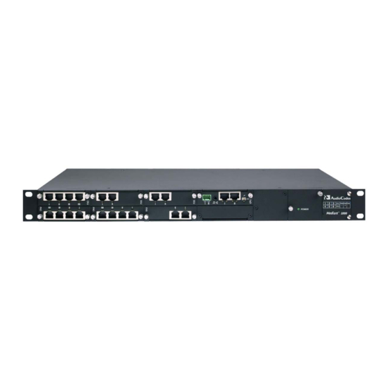
Page 22: Figure 2-2: Mediant 1000 Front Layout
I0I0 Reset button. The figure below illustrates the front layout of the Mediant 1000. There is also a schematic of the front layout on the front panel of the fan tray. To view your specific device’s configuration using the Embedded Web Server, refer to 'Monitoring the Gateway (Home Page)' on page 282. -
Page 23: I/O Modules
2. Physical Description 2.1.1 I/O Modules The Mediant 1000 can house both analog and/or digital modules: Analog modules: the gateway supports up to six replaceable analog FXO and/or FXS modules. Each module contains four analog RJ-11 ports. Therefore, the gateway can support up to 24 analog ports (6 modules x 4 ports). -
Page 24: Cpu Module
2.1.2.2 Audio IN/OUT1 The Audio IN/OUT port is indicated by the musical note and loudspeaker symbols (refer to the figure in 'Mediant 1000 Front Panel' on page 21). It is used for Music on Hold (IN) and paging (OUT). 2.1.2.3... -
Page 25: Port (Labeled I0I0)
This module is used for media server support (i.e., conferencing). The module is installed in slot 6 of the chassis front panel. For a description of Mediant 1000 conferencing capabilities, refer to 'Media Server Capabilities' on page 449. -
Page 26: Fan Tray Module
Mediant 1000 The front panel of the power supply unit provides a power supply LED that is lit green when the Mediant 1000 is powered up. If this LED does not light up, a power supply problem may be present. -
Page 27: Front Panel Leds
2. Physical Description 2.1.6 Front Panel LEDs The figure below shows the location of the front panel LEDs on the Mediant 1000. The LEDs are described in the tables below. Figure 2-11: Location of Front Panel LEDs Table 2-2: Analog I/O Modules LEDs Description... -
Page 28: Table 2-3: Digital I/O Modules Led Description
RAI - Remote Alarm Indication (the Yellow Alarm) Failure / disruption in the AC power supply or the power is currently not being supplied to the Mediant 1000 through the AC power supply entry. Table 2-4: Power Supply Module LED Description... -
Page 29: Mediant 1000 Rear Panel
SIP User's Manual 2. Physical Description Mediant 1000 Rear Panel The Mediant 1000 rear panel provides the power connectors, as shown in the figure below. Figure 2-12: Mediant 1000 Rear Connectors The table below describes the Mediant 1000 rear panel components. - Page 30 Mediant 1000 Reader's Notes SIP User's Manual Document #: LTRT-83302...
-
Page 31: Installing The Mediant 1000
Cable the Mediant 1000 (refer to 'Cabling the Mediant 1000' on page 35). After connecting the Mediant 1000 to the power source, the power LED on the front panel of the power supply unit is lit green. Any power supply malfunction results in the LED switching off (for details on the Mediant 1000 LEDs, refer to 'Front Panel LEDs' on page 27). -
Page 32: Mounting The Mediant 1000
The Mediant 1000 offers the following mounting options: Desktop mounting (refer to 'Mounting Mediant 1000 on a Desktop' on page 32) Installed in a standard 19-inch rack (refer to 'Installing Mediant 1000 in a 19-inch Rack' on page 34) 3.3.1... -
Page 33: Figure 3-2: Location Of Grooves For Rubber Feet
Figure 3-2: Location of Grooves for Rubber Feet Peel off the adhesive, anti-slide rubber feet and stick one in each anti-slide groove. Figure 3-3: Peeled-off Rubber Foot Flip the Mediant 1000 over again so that it is resting on its underside. Version 5.2 September 2007... -
Page 34: Installing Mediant 1000 In A 19-Inch Rack
Mediant 1000 3.3.2 Installing Mediant 1000 in a 19-inch Rack The Mediant 1000 can be installed in a standard 19-inch rack by implementing one of the following methods: Placing it on a pre-installed shelf in the rack (recommended method) Attaching it directly to the rack’s frame using the Mediant 1000 integral front mounting brackets and the user-adapted rear mounting brackets (not supplied). -
Page 35: Cabling The Mediant 1000
To install the Mediant 1000 in a rack without shelves, take these 2 steps: Position the Mediant 1000 in your 19-inch rack and align the front and rear (refer to note below) bracket holes to the holes (of your choosing) in the vertical tracks of the 19-inch rack. -
Page 36: Connecting To The Ethernet Network
For the RJ-45 connector pinouts, refer to the figure below. Figure 3-4: RJ-45 Connector Pinouts When assigning an IP address to the Mediant 1000 using HTTP (in Step 1 in' Assigning an IP Address Using HTTP' on page 50), you may be required to re-cable it differently. -
Page 37: Cabling The Analog Lifeline Phone
The Lifeline provides a wired analog POTS phone connection to any PSTN or PBX FXS port when there is no power, or when the network connection fails. Therefore, you can use the Lifeline phone even when the Mediant 1000 is not powered on or not connected to the network. -
Page 38: Figure 3-7: Mediant 1000 Lifeline Setup
To cable the Mediant 1000 FXS module's Lifeline, take these 3 steps: Connect the Lifeline Splitter (supplied) to Port 1 on the Mediant 1000 FXS module. Connect the Lifeline phone to Port A on the Lifeline Splitter. Connect an analog PSTN line to Port B on the Lifeline Splitter. -
Page 39: Connecting To Digital Trunks
T1 or E1 ports to the PSTN. To connect the digital trunk interfaces: Connect the E1/T1 trunk cables to the ports on the Mediant 1000 digital I/O module(s). Connect the other ends of the trunk cables to your PBX/PSTN switch. -
Page 40: Cabling The Digital Lifeline
3.4.6 Cabling the Digital Lifeline The Mediant 1000 gateway containing either one or two digital modules, each with 1 or 2 pairs of spans can provide a “lifeline” telephone link. In the event of a power failure, a relay connects trunk 1 to 2, and / or 3 to 4 in the same module. The link is provided by the closing of a metallic switch inside the module so that the trunk from the PBX is routed from the module to the PSTN. -
Page 41: Figure 3-10: Dry Contact Wires' Mate
(refer to 'Viewing the Active Alarms Table' on page 288) in the gateway's embedded Web server. The external alarm system is connected to the Mediant 1000 gateway's dry contact connector on the CPU module, using the supplied dry contact wires’ mate (refer to the figure below). -
Page 42: Connecting The Mediant 1000 Rs-232 Port To A Pc
3.4.8 Connecting the Mediant 1000 RS-232 Port to a PC The Mediant 1000 RS-232 port is used to access the CLI (refer to 'Accessing the CLI' on page 53) and to receive error / notification messages. Follow the procedure below to connect the Mediant 1000 serial (RS-232) interface to a PC. -
Page 43: Replacing Modules
3.5.1 Replacing Modules The Mediant 1000 I/O modules are hot-swappable (except for the OSN Server modules -- refer to 'OSN Server Hardware Installation' on page 487). The replacement of Mediant 1000 communication modules (i.e., digital, FXS, and FXO) is performed using the Mediant 1000 embedded Web server. -
Page 44: Inserting Modules Into Previously Empty Slots
Power off the Mediant 1000. On the Mediant 1000 front panel, using a Phillips screwdriver remove the black metal cover plate protecting the module slot. Insert the module into the empty slot, with the plain side of the Printed Circuit Board (PCB) facing up. -
Page 45: Replacing The Air Filter
SIP User's Manual 3. Installing the Mediant 1000 3.5.3 Replacing the Air Filter The fan tray module includes a removable air filter (located within the fan assembly, immediately inside the perforated grill). The air filter should be replaced approximately every 90 days and should be checked weekly to ensure it is not saturated and that it does not require cleaning / replacement. -
Page 46: Figure 3-13: Fan Tray With Filter Removed
• Alternatively, if you are replacing the filter, discard the old air filter and replace it with an air filter purchased from AudioCodes. Attach the (new / cleaned) air filter to the fan tray module; position the two holes on the filter over the pins on the fan tray. -
Page 47: Getting Started
'ini File Configuration' on page 293. An SNMP browser software (refer to the SIP Series Reference Manual). AudioCodes’ Element Management System (refer to AudioCodes’ EMS User’s Manual or EMS Product Description). To upgrade the gateway (i.e., load new software or configuration files), use the gateway's... -
Page 48: Startup Process
Mediant 1000 Startup Process The startup process (illustrated in the following figure) begins when the gateway is reset (physically, using the Embedded Web Server, or using SNMP) and ends when the operational software is running. In the startup process, the network parameters, and software and configuration files are obtained. -
Page 49: Figure 4-1: Startup Process
SIP User's Manual 4. Getting Started Figure 4-1: Startup Process Version 5.2 September 2007... -
Page 50: Assigning An Ip Address
Mediant 1000 Assigning an IP Address To assign the gateway an IP address, use one of the following methods: HTTP using a Web browser (refer to 'Assigning an IP Address Using HTTP' on page 50). BootP (refer to 'Assigning an IP Address Using BootP' on page 51). -
Page 51: Assigning An Ip Address Using Bootp
Assigning an IP Address Using BootP The procedure below describes how to assign the gateway an IP address using the supplied BootP application. For a detailed description on using AudioCodes' BootP application, refer to the SIP Series Reference Manual. Note: BootP procedure can also be performed using any standard compatible BootP server. -
Page 52: Assigning An Ip Address Using The Voice Menu Guidance
Mediant 1000 4.3.3 Assigning an IP Address Using the Voice Menu Guidance Initial configuration of the gateway can be performed using a standard touch-tone telephone connected to one of the FXS analog ports. The voice menu can also be used to query and modify basic configuration parameters. -
Page 53: Assigning An Ip Address Using The Cli
SIP User's Manual 4. Getting Started The following configuration parameters can be queried or modified via the voice menu: Table 4-2: Configuration Parameters Available via the Voice Menu Item Number at Menu Description Prompt IP address Subnet mask Default Gateway IP address Primary DNS server IP address DHCP enable / disable MGCP call agent IP address (N/A) -
Page 54: Assigning An Ip Address
232 interface. To access the CLI using the RS-232 port , take these 2 steps: Connect the gateway's RS-232 port to your PC (refer to Connecting the Mediant 1000 RS-232 Port to a PC on page Use a serial communication software (e.g., HyperTerminal... -
Page 55: Configuring Basic Parameters
SIP User's Manual 4. Getting Started Configuring Basic Parameters To configure the gateway's basic parameters, use the Embedded Web Server’s ‘Quick Setup’ screen (shown in the figure below). For information on accessing the Embedded Web Server, refer to 'Accessing the Embedded Web Server' on page 60. Figure 4-2: Quick Setup Screen To configure basic SIP parameters, take these 11 steps: Access the ‘Quick Setup’... - Page 56 Mediant 1000 When working with a Proxy server, set the ‘Working with Proxy’ field to ‘Yes’, and then enter the IP address of the primary Proxy server in the field ‘Proxy IP address’. When no Proxy is used, the internal routing table is used to route the calls.
-
Page 57: Web-Based Management
SIP User's Manual 5. Web-based Management Web-based Management The gateway's Embedded Web Server is used for remote configuration of the gateway including loading of configuration files, as well as for online monitoring of the gateway. In addition, you can also remotely reset the gateway. The Embedded Web Server can be accessed from a standard Web browser such as Microsoft™... -
Page 58: User Accounts
Mediant 1000 5.2.1 User Accounts Up to five simultaneous users can be handled on gateway authentication via the Embedded Web Server. To prevent unauthorized access to the Embedded Web Server, two user accounts are available: primary and secondary. Each account is composed of three attributes: username, password, and access level. -
Page 59: Limiting The Embedded Web Server To Read-Only Mode
SIP User's Manual 5. Web-based Management The first time a Web browser request is made, users are requested to provide their account's username and password to obtain access. If the Embedded Web Server is left idle for more than five minutes, the session expires and the user is required to re-enter username and password. -
Page 60: Accessing The Embedded Web Server
Mediant 1000 Accessing the Embedded Web Server You can access the gateway's Embedded Web Server by following the procedure below. To access the Embedded Web Server, take these 4 steps: Open a standard Web-browsing application (for a list of supported Web browsers, refer to 'Computer Requirements' on page 57). -
Page 61: Getting Acquainted With The Web Interface
Home icon: opens the Home page screen used mainly for monitoring the gateway (refer to Using the Home Page on page 282). Corporate logo: AudioCodes' corporate logo. For information on how to remove this logo, refer to 'Customizing the Web Interface' on page 65. -
Page 62: Main Menu Bar
Mediant 1000 5.4.1 Main Menu Bar The main menu bar of the Embedded Web Server provides the following menus: Quick Setup: Accesses the 'Quick Setup' screen for quickly configuring the gateway's basic settings.For a full list of configurable parameters, directly access the Protocol Management and Advanced Configuration menus. -
Page 63: Searching For Configuration Parameters
SIP User's Manual 5. Web-based Management 5.4.4 Searching for Configuration Parameters The Embedded Web Server provides a search engine that allows you to search any ini file parameter that is configurable by the Web server. The Search button, located near the bottom of the Main menu bar is used to perform parameter searches. -
Page 64: Figure 5-4: Searched Parameter Highlighted In Screen
Mediant 1000 In the searched result list, click the required parameter to open the screen in which the parameter appears; the searched parameter is highlighted in green in the screen for easy identification, as shown in the figure below. Figure 5-4: Searched Parameter Highlighted in Screen Note: If the searched parameter is not located, the "No Matches Found For This... -
Page 65: Customizing The Web Interface
69) Login welcome message (refer to 'Creating a Login Welcome Message' on page 70) The figure below displays an example of the default title bar (i.e., of AudioCodes) and below it, a customized one: Figure 5-5: Customized Web Interface Title Bar Figure 5-6: Customized Web Interface Title Bar 5.4.5.1... -
Page 66: Figure 5-7: Image Download Screen
Mediant 1000 5.4.5.1.1 Replacing the Main Corporate Logo with an Image File You can replace the logo in the Web interface's title bar using either the Embedded Web Server or the ini file. To replace the default logo with your own corporate image via the... -
Page 67: Table 5-3: Customizable Logo Ini File Parameters
5.4.5.1.2 Replacing the Main Corporate Logo with a Text String The main corporate logo can be replaced with a text string. To replace AudioCodes’ default logo with a text string using the ini file, add or modify the two ini file parameters listed in the table below (according to the procedure described in n 'Modifying an ini File' on page 293). -
Page 68: Replacing The Background Image File
Mediant 1000 5.4.5.2 Replacing the Background Image File The background image file is duplicated across the width of the screen. The number of times the image is duplicated depends on the width of the background image and screen resolution. When choosing your background image, keep this in mind. The background image file can be replaced using either the Embedded Web Server or the ini file. -
Page 69: Customizing The Product Name
5.4.5.3 Customizing the Product Name To replace AudioCodes’ default product name with a text string, add or modify the two ini file parameters listed in the table below (according to the procedure described in' Modifying an ini File' on page 293). -
Page 70: Creating A Login Welcome Message
Mediant 1000 5.4.5.4 Creating a Login Welcome Message You can create a Welcome message box (alert message) that appears (see figure below for an example) after each successful login to the gateway's Embedded Web Server. The ini file parameter table WelcomeMessage allows you to create the Welcome message. Up to 20 lines of character strings can be defined for the message. -
Page 71: Protocol Management
SIP User's Manual 5. Web-based Management Protocol Management The Protocol Management menu is used to configure the gateway's SIP parameters and tables. Note: Throughout this section, parameters enclosed in square brackets ([...]) depict the ini file parameters that correspond to the Embedded Web Server parameters. -
Page 72: General Parameters
Mediant 1000 5.5.1.1 General Parameters The General Parameters option is used to configure general SIP parameters. To configure the general SIP protocol parameters, take these 4 steps: Open the 'General Parameters' screen (Protocol Management menu > Protocol Definition submenu > General Parameters option). -
Page 73: Table 5-8: General Parameters (Protocol Definition)
SIP User's Manual 5. Web-based Management Configure the parameters according to the table below. Click the Submit button to save your changes. To save the changes to flash memory, refer to 'Saving Configuration' on page 278. Table 5-8: General Parameters (Protocol Definition) Parameter Description PRACK Mode... - Page 74 Mediant 1000 Table 5-8: General Parameters (Protocol Definition) Parameter Description Enable Early Media If enabled, the gateway sends 183 Session Progress response with SDP [EnableEarlyMedia] (instead of 180 Ringing), allowing the media stream to be set up prior to the answering of the call.
- Page 75 SIP User's Manual 5. Web-based Management Table 5-8: General Parameters (Protocol Definition) Parameter Description [0] Disabled = None (default) Asserted Identity Mode [AssertedIdMode] [1] Adding PAsserted Identity [2] Adding PPreferred Identity The Asserted ID mode defines the header that is used in the generated INVITE request.
- Page 76 Mediant 1000 Table 5-8: General Parameters (Protocol Definition) Parameter Description [0] Initiate T.38 on Preamble = Terminating fax gateway initiates T.38 Detect Fax on Answer session on receiving HDLC preamble signal from fax (default) Tone [DetFaxOnAnswerTone] [1] Initiate T.38 on CED = Terminating fax gateway initiates T.38 session on receiving CED answer tone from fax.
- Page 77 SIP User's Manual 5. Web-based Management Table 5-8: General Parameters (Protocol Definition) Parameter Description Use “user=phone” in [0] No = Doesn't use ';user=phone' string in From header (default). From Header [1] Yes = ';user=phone' string is part of the From header. [IsUserPhoneInFrom] Use Tel URI for Asserted Determines the format of the URI in the P-Asserted and P-Preferred...
- Page 78 Mediant 1000 Table 5-8: General Parameters (Protocol Definition) Parameter Description Enable History-Info Enables usage of the History-Info header. Header Valid options include: [EnableHistoryInfo] [0] Disable = Disable (default) [1] Enable = Enable UAC Behavior: Initial request: The History-Info header is equal to the Request URI. If a PSTN Redirect number is received, it is added as an additional History- Info header with an appropriate reason.
-
Page 79: Parameter Description
SIP User's Manual 5. Web-based Management Table 5-8: General Parameters (Protocol Definition) Parameter Description Use Source Number as Applicable to Tel-to-IP calls. Display Name [0] No = The Tel Source Number is used as the IP Source Number and [UseSourceNumberAsD the Tel Display Name is used as the IP Display Name (if Tel Display isplayName] Name is received). - Page 80 Mediant 1000 Table 5-8: General Parameters (Protocol Definition) Parameter Description [0] Don't Play = Ringback tone isn't played to the IP side of the call Play Ringback Tone to IP (default). [PlayRBTone2IP] [1] Play = Ringback tone is played to the IP side of the call after SIP 183 session progress response is sent (for analog interfaces, this applies only to FXS modules;...
- Page 81 Defines the string that is used in the SIP request header 'User-Agent' and [UserAgentDisplayInfo] SIP response header 'Server'. If not configured, the default string 'AudioCodes product-name s/w-version' is used (e.g., User-Agent: Audiocodes-Sip-Gateway-Mediant 1000/v.4.80.004.008). When configured, the string 'UserAgentDisplayInfo s/w-version' is used (e.g., User-Agent: MyNewOEM/v.4.80.004.008).
- Page 82 Mediant 1000 Table 5-8: General Parameters (Protocol Definition) Parameter Description Play Busy Tone to Tel Enables the ISDN gateway to play a Busy or a Reorder tone to the PSTN [PlayBusyTone2ISDN] after a call is released. [0] Don't Play = Immediately sends an ISDN Disconnect message (default).
- Page 83 SIP User's Manual 5. Web-based Management Table 5-8: General Parameters (Protocol Definition) Parameter Description Enable P-Charging Enables the addition of a P-Charging-Vector header to all outgoing INVITE Vector messages. [EnablePChargingVecto Valid options include: [0] Disable = Disable (default) [1] Enable = Enable Enable VoiceMail URI Enables or disables the interworking of target and cause for redirection [EnableVMURI]...
-
Page 84: Proxy & Registration Parameters
Mediant 1000 Table 5-8: General Parameters (Protocol Definition) Parameter Description SIP Maximum RTX Number of UDP transmissions (first transmission plus retransmissions) of [SIPMaxRtx] SIP messages. The range is 1 to 30. The default value is 7. 5.5.1.2 Proxy & Registration Parameters The Proxy &... -
Page 85: Table 5-9: Proxy & Registration Parameters
SIP User's Manual 5. Web-based Management Configure the Proxy and Registration parameters according to the following table. Click the Submit button to save your changes, or click the Register or Un-Register buttons to save your changes and register / unregister to a Proxy / Registrar. To save the changes to flash memory, refer to 'Saving Configuration' on page 278. - Page 86 Mediant 1000 Table 5-9: Proxy & Registration Parameters Parameter Description First Redundant Proxy IP addresses of the first redundant Proxy you are using. IP Address Enter the IP address as FQDN or in dotted decimal notation (e.g., [ProxyIP] 192.10.1.255). You can also specify the selected port in the format <IP Address>:<port>.
- Page 87 SIP User's Manual 5. Web-based Management Table 5-9: Proxy & Registration Parameters Parameter Description Proxy Load Balancing Enables the usage of the Proxy Load Balancing mechanism. Method [0] Disable = Load Balancing is disabled (default). [ProxyLoadBalancing [1] Round Robin = Round Robin. Method] [2] Random Weights = Random Weights.
- Page 88 Mediant 1000 Table 5-9: Proxy & Registration Parameters Parameter Description Enable Proxy Keep Determines whether Keep-Alive with the Proxy is enabled or disabled. Alive [0] Disable = Disable (default)\ [EnableProxyKeepAli [1] Using OPTIONS = Enable Keep alive with Proxy using OPTIONS...
- Page 89 SIP User's Manual 5. Web-based Management Table 5-9: Proxy & Registration Parameters Parameter Description Use Routing Table for Use the internal Tel to IP routing table to obtain the URI Host name and Host Names and (optionally) an IP profile (per call), even if Proxy server is used. Profiles [0] Disable = Don't use (default).
- Page 90 Mediant 1000 Table 5-9: Proxy & Registration Parameters Parameter Description Registrar IP Address IP address (numerical or FQDN) and optionally port number of Registrar [RegistrarIP] server. Enter the IP address in dotted format notation, for example, 201.10.8.1:<5080>. Notes: If not specified, the REGISTER request is sent to the primary Proxy server (refer to 'Proxy IP address' parameter).
- Page 91 SIP User's Manual 5. Web-based Management Table 5-9: Proxy & Registration Parameters Parameter Description Miscellaneous parameters Gateway Name Assigns a name to the gateway (e.g., 'gateway1.com'). Ensure that the [SIPGatewayName] name you choose is the one that the Proxy is configured with to identify your gateway.
- Page 92 Mediant 1000 Table 5-9: Proxy & Registration Parameters Parameter Description Proxy DNS Query Type Enables the use of DNS Naming Authority Pointer (NAPTR) and Service [ProxyDNSQueryType Record (SRV) queries to discover Proxy servers. Valid options include: [0] A-Record = A-Record (default)
- Page 93 SIP User's Manual 5. Web-based Management Table 5-9: Proxy & Registration Parameters Parameter Description Number of RTX Before Number of retransmitted INVITE/REGISTER messages before call is routed Hot-Swap (hot swap) to another Proxy/Registrar. [HotSwapRtx] The valid range is 1 to 30. The default value is 3. Note: This parameter is also used for alternative routing using the Tel to IP Routing table.
-
Page 94: Coders
Mediant 1000 Table 5-9: Proxy & Registration Parameters Parameter Description Challenge Caching Determines the mode used for Challenge Caching. Challenge Caching is Mode used to reduce the number of SIP messages transmitted through the [SIPChallengeCachin network. The first request to the Proxy is sent without authorization. The gMode] Proxy sends a 401/407 response with a challenge. -
Page 95: Figure 5-11: Coders Screen
SIP User's Manual 5. Web-based Management To configure the gateway's coders, take these 9 steps: Open the 'Coders' screen (Protocol Management menu > Protocol Definition submenu > Coders option). Figure 5-11: Coders Screen From the 'Coder Name' drop-down list, select the coder you want to use. For the full list of available coders and their corresponding attributes, refer to the table below. -
Page 96: Table 5-10: Supported Coders
Mediant 1000 Notes: • Each coder (i.e., 'Coder Name') can appear only once. • If packetization time and / or rate are not specified, the default value is applied. • The ptime specifies the packetization time the gateway expects to receive. - Page 97 SIP User's Manual 5. Web-based Management Table 5-10: Supported Coders Coder Name Packetization Time Rate Payload Type Silence Suppression NetCoder 20 (default), 40, 60, 6.4 [0]; Disable [0] [NetCoder] 80, 100, 120 Enable [1] 7.2 [1] 8.0 [2] 8.8 [3] (default) G.711A-law_VBD 10, 20 (default), 30,...
-
Page 98: Dtmf & Dialing Parameters
Mediant 1000 5.5.1.4 DTMF & Dialing Parameters The DTMF & Dialing option is used to configure parameters associated with dual-tone multi-frequency (DTMF) and dialing. To configure the DTMF and dialing parameters, take these 4 steps: Open the 'DTMF & Dialing' screen (Protocol Management menu > Protocol Definition submenu >... -
Page 99: Table 5-11: Dtmf And Dialing Parameters
SIP User's Manual 5. Web-based Management Table 5-11: DTMF and Dialing Parameters Parameter Description Max Digits in Phone Num Defines the maximum number of collected destination number digits that [MaxDigits] can be received (i.e., dialed) from the Tel side when Tel-to-IP overlap dialing is performed (ISDN uses overlap dialing). - Page 100 Mediant 1000 Table 5-11: DTMF and Dialing Parameters Parameter Description to 5 Tx DTMF Option Determines a single or several preferred transmit DTMF negotiation [TxDTMFOption] methods. Valid options include: [0] Not Supported = No negotiation, DTMF digits are sent according to the parameters DTMFTransportType and RFC2833PayloadType (default).
- Page 101 SIP User's Manual 5. Web-based Management Table 5-11: DTMF and Dialing Parameters Parameter Description Hook-Flash Option Supported hook-flash Transport Type (method by which hook-flash is sent [HookFlashOption] and received). Valid options include: [0] Not Supported = Hook-Flash indication isn't sent (default) [1] INFO = Send proprietary INFO message with Hook-Flash indication [4] RFC 2833 Notes:...
-
Page 102: Configuring The Advanced Parameters
Mediant 1000 Table 5-11: DTMF and Dialing Parameters Parameter Description Hotline Dial Tone Duration (in seconds) of the Hotline dial tone. Duration If no digits are received during the Hotline dial tone duration, the gateway [HotLineToneDuration] initiates a call to a preconfigured number (set in the 'Automatic Dialing' table). -
Page 103: General Parameters
SIP User's Manual 5. Web-based Management 5.5.2.1 General Parameters The General Parameters option is used to configure general control protocol parameters. To configure the advanced general protocol parameters, take these 4 steps: Open the 'General Parameters' screen (Protocol Management menu > Advanced Parameters submenu >... -
Page 104: Table 5-12: General Parameters (Advanced Parameters)
Mediant 1000 Configure the parameters according to the table below. Click the Submit button to save your changes. To save the changes to flash memory, refer to 'Saving Configuration' on page 278. Table 5-12: General Parameters (Advanced Parameters) Parameter Description [0] Disable = gateway accepts all SIP calls (default). - Page 105 SIP User's Manual 5. Web-based Management Table 5-12: General Parameters (Advanced Parameters) Parameter Description [0] Disable = Disabled (default). Enable Digit Delivery to Tel [EnableDigitDelivery] [1] Enable = Enable Digit Delivery feature for the FXO/FXS gateway The digit delivery feature enables sending DTMF digits to the gateway's port after the call is answered [line offhooked (FXS) or seized (FXO)].
- Page 106 Mediant 1000 Table 5-12: General Parameters (Advanced Parameters) Parameter Description PSTN Alert Timeout For Digital: Alert Timeout (in seconds) (ISDN T301 timer) for outgoing [PSTNAlertTimeout] calls to PSTN. This timer is used between the time SETUP is sent to the Tel side (IP to Tel call establishment) and CONNECT is received.
- Page 107 SIP User's Manual 5. Web-based Management Table 5-12: General Parameters (Advanced Parameters) Parameter Description [0] Disable = Disable the current disconnect service (default). Enable Current Disconnect [EnableCurrentDisconnec [1] Enable = Enable the current disconnect service. If the current disconnect service is enabled, the FXO releases a call when current disconnect signal is detected on its port, while the FXS module generates a 'Current Disconnect Pulse' after a call is released from IP.
- Page 108 Mediant 1000 Table 5-12: General Parameters (Advanced Parameters) Parameter Description Silence Detection Method Silence detection method. [FarEndDisconnectSilenc [0] None = Silence detection option is disabled. eMethod] [1] Packets Count = According to packet count. [2] Voice/Energy Detectors = N/A. [3] All = N/A.
- Page 109 SIP User's Manual 5. Web-based Management Table 5-12: General Parameters (Advanced Parameters) Parameter Description Debug Level Syslog logging level. One of the following debug levels can be selected: [GwDebugLevel] [0] 0 = Debug is disabled (default) [1] 1 = Flow debugging is enabled [2] 2 = Flow and device interface debugging are enabled [3] 3 = Flow, device interface and stack interface debugging are enabled...
- Page 110 Mediant 1000 Table 5-12: General Parameters (Advanced Parameters) Parameter Description [0] Disable = 'Busy out' feature is not used (default). Enable Busy Out [EnableBusyOut] [1] Enable = 'Busy out' feature is enabled. When Busy Out is enabled and certain scenarios exist, the gateway...
- Page 111 SIP User's Manual 5. Web-based Management Table 5-12: General Parameters (Advanced Parameters) Parameter Description Max Number of Active Defines the maximum number of simultaneous active calls supported by Calls the gateway. If the maximum number of calls is reached, new calls are [MaxActiveCalls] not established.
- Page 112 Mediant 1000 Table 5-12: General Parameters (Advanced Parameters) Parameter Description Out-Of-Service Behavior Determines the behavior of FXS endpoints that are not defined (in the [FXSOOSBehavior] Endpoint Phone Number table), and the behavior of all FXS endpoints when a Busy-Out condition exists.
-
Page 113: Supplementary Services
SIP User's Manual 5. Web-based Management 5.5.2.2 Supplementary Services The Supplementary Services option is used to configure parameters that are associated with supplementary services. For detailed information on supplementary services, refer to 'Working with Supplementary Services' on page 415. To configure the supplementary services' parameters, take these 4 steps: Open the 'Supplementary Services' screen (Protocol Management menu >... -
Page 114: Table 5-13: Supplementary Services Parameters
Mediant 1000 Click the Submit button to save your changes, or click the Subscribe to MWI or Unsubscribe to MWI buttons to save your changes and to subscribe / unsubscribe to the MWI server. To save the changes to flash memory, refer to 'Saving Configuration' on page 278. - Page 115 SIP User's Manual 5. Web-based Management Table 5-13: Supplementary Services Parameters Parameter Description [0] Disable = Disable the Call Forward service. Enable Call Forward [EnableForward] [1] Enable = Enable Call Forward service (using REFER) (default). For FXS modules, a Call Forward table must be defined to use the Call Forward service.
- Page 116 Mediant 1000 Table 5-13: Supplementary Services Parameters Parameter Description [0] Disable = Disable the Caller ID service (default). Enable Caller ID [EnableCallerID] [1] Enable = Enable the Caller ID service. If the Caller ID service is enabled, then, for FXS modules, calling number and Display text are sent to the gateway port.
- Page 117 SIP User's Manual 5. Web-based Management Table 5-13: Supplementary Services Parameters Parameter Description MWI Parameters Enable MWI Enable MWI (Message Waiting Indication). [EnableMWI] [0] Disable = Disabled (default). [1] Enable = MWI service is enabled. Notes: This parameter is applicable only to FXS modules. The gateway supports only the reception of SIP MWI NOTIFY messages (the gateway doesn't generate these messages).
-
Page 118: Metering Tones
Conference-initiating INVITE that is sent to the media server when Enable3WayConference is set to 1. When using the Mediant 1000 Media Process Module (MPM): To join a conference, the INVITE URI must include the Conference ID string, preceded by the number of the participants in the conference, and terminated by a unique number. -
Page 119: Figure 5-15: Metering Tones Parameters Screen
SIP User's Manual 5. Web-based Management To configure the Metering Tones, take these 6 steps: Open the 'Metering Tones' screen (Protocol Management menu > Advanced Parameters submenu > Metering Tones option). Figure 5-15: Metering Tones Parameters Screen From the 'Metering Tone Type' drop-down list, select the type of the metering tone according to your requirements (refer to the table below). -
Page 120: Keypad Features
Mediant 1000 5.5.2.3.1 Charge Codes Table The Charge Codes table is used to configure the metering tones (and their time interval) that the FXS modules generate to the Tel side. To associate a charge code to an outgoing Tel-to-IP call, use the 'Tel to IP Routing' table. -
Page 121: Figure 5-17: Keypad Features Screen
SIP User's Manual 5. Web-based Management To configure the keypad features, take these 4 steps: Open the 'Keypad Features' screen (Protocol Management menu > Advanced Parameters submenu > Keypad Features option). Figure 5-17: Keypad Features Screen Configure the Keypad Features according to the table below. Click the Submit button to save your changes. -
Page 122: Table 5-15: Keypad Features Parameters
Mediant 1000 Table 5-15: Keypad Features Parameters Parameter Description Forward Note that the forward type and number can be viewed in the Call Forward Table (refer to 'Call Forward' on page 157) Unconditional Keypad sequence that activates the immediate forward option. -
Page 123: Stand-Alone Survivability
SIP User's Manual 5. Web-based Management Table 5-15: Keypad Features Parameters Parameter Description Transfer Blind Keypad sequence that activates the blind transfer option. After this [KeyBlindTransfer] sequence is dialed, the current call is put on hold, a dial tone is played to the phone, and then phone number collection starts. -
Page 124: Figure 5-18: Stand-Alone Survivability Screen
Mediant 1000 during Emergency mode, the SAS can continue functioning in Normal mode. Alternatively, the SAS can be simplified by carelessly handling existing calls. To configure the Stand-Alone Survivability parameters, take these 4 steps: Open the 'Supplementary Services' screen (Protocol Management menu >... -
Page 125: Configuring The Number Manipulation Tables
SIP User's Manual 5. Web-based Management 5.5.3 Configuring the Number Manipulation Tables The VoIP gateway provides four Number Manipulation tables for incoming and outgoing calls. These tables are used to modify the destination and source telephone numbers so that the calls can be routed correctly. The Manipulation Tables include: Destination Phone Number Manipulation Table for IP-to-Tel calls Destination Phone Number Manipulation Table for Tel-to-IP calls... -
Page 126: Figure 5-19: Source Phone Number Manipulation Table For Tel-To-Ip Calls
Mediant 1000 To configure the Number Manipulation tables, take these 5 steps: Open the required 'Number Manipulation' screen (Protocol Management menu > Manipulation Tables submenu); the relevant Manipulation table screen is displayed (e.g., 'Source Phone Number Manipulation Table for Tel IP Calls' screen). -
Page 127: Table 5-17: Number Manipulation Parameters
SIP User's Manual 5. Web-based Management Table 5-17: Number Manipulation Parameters Parameter Description Destination Prefix Destination (called) telephone number prefix. An asterisk (*) represents any number. Source Prefix Source (caller) telephone number prefix. An asterisk (*) represents any number. Source IP Source IP address of the call (obtained from the Contact header in the (Applicable only to the INVITE message). -
Page 128: Dialing Plan Notation
Mediant 1000 Table 5-17: Number Manipulation Parameters Parameter Description Select the Numbering Plan Indicator (NPI) assigned to this entry. [0] Unknown (default) [9] Private [1] E.164 Public [-1] Not Configured = value received from PSTN/IP is used For a detailed list of the available NPI/TON values, refer to Numbering Plans and Type of Number on page Select the Type of Number (TON) assigned to this entry. -
Page 129: Numbering Plans And Type Of Number
SIP User's Manual 5. Web-based Management The gateway matches the rules starting at the top of the table (i.e., top rules take precedence over lower rules). For this reason, enter more specific rules above more generic rules. For example, if you enter 551 in entry 1 and 55 in entry 2, the gateway applies rule 1 to numbers that starts with 551 and applies rule 2 to numbers that start with 550, 552, 553, 554, 555, 556, 557, 558 and 559. -
Page 130: Mapping Npi/Ton To Phone-Context
Mediant 1000 5.5.3.3 Mapping NPI/TON to Phone-Context The Phone-Context Table option is used to configure the mapping of NPI and TON to the Phone-Context SIP parameter. When a call is received from the ISDN/Tel, the NPI and TON are compared against the table and the Phone-Context value is used in the outgoing SIP INVITE message. -
Page 131: Table 5-20: Phone-Context Parameters
SIP User's Manual 5. Web-based Management Click the Submit button to save your changes. To save the changes to flash memory, refer to 'Saving Configuration' on page 278. Notes: • Several rows with the same NPI-TON or Phone-Context are allowed. In such a scenario, a Tel-to-IP call uses the first match. -
Page 132: Configuring The Routing Tables
Mediant 1000 5.5.4 Configuring the Routing Tables The Routing Tables submenu is used to configure the gateway's IP-to-Tel and Tel-to-IP routing tables and their associated parameters: General Parameters (refer to 'General Parameters' on page 132) Tel to IP Routing Table (refer to 'Tel to IP Routing Table' on page 134) -
Page 133: Table 5-21: General Parameters (Routing Tables)
SIP User's Manual 5. Web-based Management Table 5-21: General Parameters (Routing Tables) Parameter Description [0] No = Don't add trunk group ID as prefix (default). Add Trunk Group ID as Prefix [1] Yes = Add trunk group ID as prefix to called number. [AddTrunkGroupAsPref If enabled, then the gateway's trunk group ID is added as a prefix to the destination phone number for Tel-to-IP calls. -
Page 134: Tel To Ip Routing Table
Mediant 1000 Table 5-21: General Parameters (Routing Tables) Parameter Description Enable Alt Routing Tel to Determines the operation modes for the Alternative Routing mechanism. [0] Disable = Disable the Alternative Routing feature (default). [AltRoutingTel2IPEnabl [1] Enable = Enable the Alternative Routing feature. - Page 135 SIP User's Manual 5. Web-based Management When using a Proxy server, you do not need to configure the Tel to IP Routing Table. However, if you want to use fallback routing when communication with Proxy servers is lost, or to use the 'Filter Calls to IP' and 'IP Security' features, or to obtain different SIP URI host names (per called number) or to assign IP profiles, you need to configure the IP Routing Table.
-
Page 136: Figure 5-21: Tel To Ip Routing Screen
Mediant 1000 Note: If the alternative routing destination is the gateway itself, the call can be configured to be routed back to PSTN. This feature is referred to as 'PSTN Fallback', meaning that if sufficient voice quality is not available over the IP network, the call is routed through the legacy telephony system (PSTN). -
Page 137: Table 5-22: Tel To Ip Routing Table
SIP User's Manual 5. Web-based Management Table 5-22: Tel to IP Routing Table Parameter Description Tel to IP Routing Mode Defines the order between routing incoming calls to IP, using routing table, [RouteModeTel2IP] and manipulation of destination number. [0] Route calls before manipulation = Tel-to-IP calls are routed before the number manipulation rules are applied (default). -
Page 138: Ip To Trunk Group Routing
Mediant 1000 5.5.4.3 IP to Trunk Group Routing The IP to Trunk Group Routing Table is used to route incoming IP calls to groups of channels (for digital modules, these are E1/T1 B-channels) called trunk groups. Calls are assigned to trunk groups according to any combination of the following three options (or... -
Page 139: Figure 5-22: Ip To Trunk Group Routing Table Screen
SIP User's Manual 5. Web-based Management To configure the IP to Trunk Group Routing table, take these 6 steps: Open the 'IP to Trunk Group Routing' screen (Protocol Management menu > Routing Tables submenu > IP to Trunk Group Routing option). Figure 5-23: IP to Trunk Group Routing Table Screen From the 'IP to Tel Routing Mode' field, select the IP to Tel routing mode (refer to the table below). -
Page 140: Internal Dns Table
Mediant 1000 Table 5-23: IP to Trunk Group Routing Table Parameter Description Source IP Address Represents the source IP address of an IP-to-Tel call (obtained from the Contact header in the INVITE message). Note: The source IP address can include the 'x' wildcard to represent single digits. -
Page 141: Internal Srv Table
SIP User's Manual 5. Web-based Management To configure the internal DNS table, take these 7 steps: Open the 'Internal DNS Table' screen (Protocol Management menu > Routing Tables submenu > Internal DNS Table option). Figure 5-24: Internal DNS Table Screen In the 'Domain Name' field, enter the host name to be translated. -
Page 142: Reasons For Alternative Routing
Mediant 1000 To configure the Internal SRV table, take these 9 steps: Open the 'Internal SRV Table' screen (Protocol Management menu > Routing Tables submenu > Internal SRV Table option). Figure 5-25: Internal SRV Table Screen In the 'Domain Name' field, enter the hostname to be translated. You can enter a string up to 31 characters long. -
Page 143: Figure 5-25: Reasons For Alternative Routing Screen
SIP User's Manual 5. Web-based Management You can use the 'Reasons for Alternative Routing' screen in the following example scenarios: For Tel-to-IP calls: when there is no response to an INVITE message (after INVITE retransmissions), and the gateway then issues an internal 408 'No Response' implicit release reason. -
Page 144: Release Cause Mapping
Mediant 1000 5.5.4.7 Release Cause Mapping The 'Release Cause Mapping' screen consists of two tables that allow the gateway to map up to 12 different SIP Responses to Q.850 Release Causes and vice versa, thereby overriding the hard-coded mapping mechanism (described in 'Release Cause Mapping' on page 144). -
Page 145: Coder Group Settings
SIP User's Manual 5. Web-based Management Use the Profile Definitions submenu to configure profiles: Coder Group Settings (refer to 'Coder Group Settings' on page 145) Tel Profile Settings (refer to 'Tel Profile Settings' on page 146) IP Profile Settings (refer to 'IP Profile Settings' on page 148) Note: The default values of the parameters in the Tel and IP Profiles are identical to the Embedded Web Server/ini file parameter values. -
Page 146: Tel Profile Settings
Mediant 1000 From the 'Coder Group ID' drop-down list, select a coder group ID that you want to add (up to four coder groups can be configured). From the 'Coder Name' drop-down list, select the first coder for the coder group. For a... - Page 147 SIP User's Manual 5. Web-based Management To configure Tel Profiles, take these 9 steps: Open the 'Tel Profile Settings' screen (Protocol Management menu > Profile Definitions submenu > Tel Profile Settings option). From the 'Profile ID' drop-down list, select the Tel Profile identification number you want to edit (up to four Tel Profiles can be configured).
-
Page 148: Ip Profile Settings
Mediant 1000 From the 'Profile Preference' drop-down list, select the preference (1-20) of the current Profile. The preference option is used to determine the priority of the Profile. Where '20' is the highest preference value. If both IP and Tel profiles apply to the same call, the coders and other common parameters (noted by an asterisk in the description of the parameter TelProfile) of the preferred Profile are applied to that call. - Page 149 SIP User's Manual 5. Web-based Management To configure the IP Profile settings, take these 9 steps: Open the 'IP Profile Settings' screen (Protocol Management menu > Profile Definitions submenu > IP Profile Settings option. Figure 5-29: IP Profile Settings Screen From the 'Profile ID' drop-down list, select the IP Profile you want to edit (up to four IP Profiles can be configured).
-
Page 150: Configuring The Trunk Group Table
Mediant 1000 From the 'Profile Preference' drop-down list, select the preference (1-20) of the current Profile. The preference option is used to determine the priority of the Profile. Where '20' is the highest preference value. If both IP and Tel profiles apply to the same call, the coders and other common parameters (noted by an asterisk in the description of the parameter IPProfile) of the preferred Profile are applied to that call. -
Page 151: Table 5-24: Trunk Group Table
SIP User's Manual 5. Web-based Management Table 5-24: Trunk Group Table Parameter Description Module The module for which you want to define the trunk group. Valid options include: Module 1 Digital Module 2 FXO Module 3 FXS From Trunk Starting physical trunk number (). Note: Applicable only to digital modules. -
Page 152: Configuring The Trunk Group Settings
Mediant 1000 5.5.7 Configuring the Trunk Group Settings The Trunk Group Settings option is used to determine the method in which new calls are assigned to channels within each trunk group. If such a rule doesn't exist (for a specific Trunk group), the global rule, defined by the 'Channel Select Mode' parameter (Protocol Definition >... -
Page 153: Table 5-25: Hunt Group Settings Parameters
SIP User's Manual 5. Web-based Management Table 5-25: Hunt Group Settings Parameters Mode Description Trunk Group ID Trunk Group ID to which you want to determine the method in which new calls are assigned to channels within the trunk group. Channel Select Method in which new calls are assigned to channels within the Trunk Group Mode... -
Page 154: Configuring The Endpoint Settings
Mediant 1000 5.5.8 Configuring the Endpoint Settings The Endpoint Settings submenu enables you to configure port-specific parameters. Note: The Endpoint Settings menu is only applicable to the analog modules. 5.5.8.1 Authentication The 'Authentication' screen (typically used for FXS modules) defines a username and password combination for authenticating each gateway port. -
Page 155: Automatic Dialing
SIP User's Manual 5. Web-based Management In the 'User Name' and 'Password' fields for a port, enter the username and password combination respectively. Repeat Step 3 for each port. Click the Submit button to save your changes. To save the changes to flash memory, refer to 'Saving Configuration' on page 278. 5.5.8.2 Automatic Dialing The 'Automatic Dialing' screen is used to define telephone numbers that are automatically... -
Page 156: Caller Id
Mediant 1000 Click the Submit button to save your changes. To save the changes to flash memory, refer to 'Saving Configuration' on page 278. Notes: • After a ring signal is detected on an 'Enabled' FXO port, the gateway initiates a call to the destination number without seizing the line. The line is seized only after the call is answered. -
Page 157: Call Forward
SIP User's Manual 5. Web-based Management In the' Caller ID/Name' field, enter the Caller ID string. The Caller ID string can contain up to 18 characters. Note that when the FXS modules receives 'Private' or 'Anonymous' strings in the From header, it doesn't send the calling name or number to the Caller ID display. -
Page 158: Table 5-26: Call Forward Table
Mediant 1000 To configure the Call Forward table, take these 4 steps: Open the 'Call Forward Table' screen (Protocol Management menu > Endpoint Settings submenu > Call Forward option). Configure the Call Forward parameters for each port according to the table below. -
Page 159: Caller Id Permissions
SIP User's Manual 5. Web-based Management 5.5.8.5 Caller ID Permissions The 'Caller ID Permissions' screen is used to enable or disable (per port) the Caller ID generation (for FXS modules) and detection (for FXO modules). If a port isn't configured, its Caller ID generation / detection are determined according to the global parameter EnableCallerID (described in 'Supplementary Services' on page 113). -
Page 160: Call Waiting
Mediant 1000 5.5.8.6 Call Waiting The 'Call Waiting' screen is used to configure call waiting per gateway port. You can also configure the Call Waiting table using the ini file parameter CallWaitingPerPort (refer to 'SIP Configuration Parameters' on page 323). -
Page 161: Configuring The Digital Gateway Parameters
SIP User's Manual 5. Web-based Management 5.5.9 Configuring the Digital Gateway Parameters The 'Digital Gateway' screen is used to configure miscellaneous digital parameters. To configure the digital gateway parameters, take these 4 steps: Open the 'Digital gateway Parameters' screen (Protocol Management menu > Digital Gateway Parameters). -
Page 162: Table 5-27: Digital Gateway Parameters
Mediant 1000 Table 5-27: Digital Gateway Parameters Parameter Description B-channel Negotiation Determines the ISDN B-Channel negotiation mode. [BchannelNegotiation] [0] Preferred = Preferred [1] Exclusive = Exclusive (default) [2] Any = Any Notes: Applicable to ISDN protocols. • The Any option is only applicable if TerminationSide = 0 (User •... - Page 163 SIP User's Manual 5. Web-based Management Table 5-27: Digital Gateway Parameters Parameter Description Send Screening Indicator to Overwrites the screening indicator of the calling number for ISDN IP Tel (ISDN) calls. [ScreeningInd2ISDN] [-1] Not Configured = Not configured (interworking from IP to ISDN) (default).
- Page 164 Mediant 1000 Table 5-27: Digital Gateway Parameters Parameter Description Enable ISDN Tunneling Tel to IP Valid options include: [EnableISDNTunnelingTel2IP] [0] Disable = Disable (default). [1] Using Header = Enable ISDN Tunneling from ISDN PRI to SIP using a proprietary SIP header.
- Page 165 SIP User's Manual 5. Web-based Management Table 5-27: Digital Gateway Parameters Parameter Description [0] Alert = Enable ISDN Transfer if outgoing call is in Alert state ISDN Transfer On Connect (default). [SendISDNTransferOnConnect] [1] Connect = Enable ISDN Transfer only if outgoing call is in Connect state.
-
Page 166: Configuring The Advanced Applications
Mediant 1000 Table 5-27: Digital Gateway Parameters Parameter Description MLPP Default Namespace Determines the Namespace used for MLPP calls received from the [MLPPDefaultNamespace] ISDN side and destined for the Application Server. The Namespace value is not present in the Precedence IE of the PRI SETUP message. -
Page 167: Table 5-28: Radius Parameters
SIP User's Manual 5. Web-based Management To configure the RADIUS parameters, take these 4 steps: Open the ‘RADIUS Parameters' screen (Protocol Management menu > Advanced Applications submenu > RADIUS Parameters). Figure 5-33: RADIUS Parameters Screen Configure the RADIUS accounting parameters according to the table below. Click the Submit button to save your changes. -
Page 168: Configuring The Fxo Parameters
Mediant 1000 5.5.10.2 Configuring the FXO Parameters The 'FXO Settings' screen is used to configure the gateway's specific FXO parameters. Note: The 'FXO Settings' screen is only available for gateways providing FXO interface. To configure the FXO parameters, take these 4 steps: Open the 'FXO Settings' screen (Protocol Management menu >... -
Page 169: Table 5-29: Fxo Parameters
SIP User's Manual 5. Web-based Management Table 5-29: FXO Parameters Parameter Description Dialing Mode Used for IP FXO modules calls. [IsTwoStageDial] [0] One Stage = One-stage dialing. [1] Two Stages = Two-stage dialing (default). If two-stage dialing is enabled, then the FXO module seizes one of the PSTN/PBX lines without performing any dial, the remote user is connected over IP to PSTN/PBX, and all further signaling (dialing and Call Progress Tones) is performed directly with the PBX without the gateway's... - Page 170 Mediant 1000 Table 5-29: FXO Parameters Parameter Description Ring Detection Timeout Note: Applicable only to FXO modules for Tel IP calls. [sec] The Ring Detection timeout is used differently for normal and for automatic [FXOBetweenRingTime] dialing. If automatic dialing is not used, and if Caller ID is enabled, then the FXO module seizes the line after detection of the second ring signal (allowing detection of caller ID, sent between the first and the second rings).
- Page 171 SIP User's Manual 5. Web-based Management Table 5-29: FXO Parameters Parameter Description Disconnect on Dial Tone FXO modules can disconnect a call after a dial tone from the PBX is [DisconnectOnDialTone detected. [0] Disable = Call isn't released. [1] Enable = Call is released if dial tone is detected on the gateway's FXO port (default).
-
Page 172: Configuring The Voice Mail (Vm) Parameters
Mediant 1000 5.5.10.3 Configuring the Voice Mail (VM) Parameters The 'Voice Mail' screen is used to configure the Voice Mail (VM) parameters. The VM application applies only to FXO/CAS modules. For detailed information on VM, refer to the CPE Configuration Guide for Voice Mail User's Manual. -
Page 173: Table 5-30: Voice Mail Parameters
SIP User's Manual 5. Web-based Management Table 5-30: Voice Mail Parameters Parameter Description General Voice Mail Interface Enables the VM application on the gateway and determines the [VoiceMailInterface] communication method used between the PBX and the gateway. [0] None (default) [1] DTMF [2] SMDI (N/A)[3] QSIG [4] SETUP Only (ISDN) - Page 174 Mediant 1000 Table 5-30: Voice Mail Parameters Parameter Description Forward on No Answer Digit Determines the digit pattern used by the PBX to indicate 'call forward on Pattern (Internal) no answer' when the original call is received from an internal extension.
-
Page 175: Configuring The Ipmedia Parameters
SIP User's Manual 5. Web-based Management Table 5-30: Voice Mail Parameters Parameter Description MWI Suffix Pattern Determines a digit code used by the gateway as a suffix for MWIOnCode [MWISuffixCode] and MWIOffCode. This suffix is added to the generated DTMF string after the extension number. -
Page 176: Table 5-31: Ipmedia Configuration Parameters
Mediant 1000 Table 5-31: IPmedia Configuration Parameters ini File Field Name Valid Range and Description Web Parameter Name Number of Media The number of DSP channels that are allocated for IP conferences, IP Channels streaming and IP Transcoding (other DSP channels can be used for [MediaChannels] PSTN Gateway). - Page 177 SIP User's Manual 5. Web-based Management Table 5-31: IPmedia Configuration Parameters ini File Field Name Valid Range and Description Web Parameter Name Enable DTMF Clamping Determines the gateway logic once a DTMF is received on any [EnableConferenceDTM conference participant. If enabled, the DTMF is not regenerated towards FClamp] the other conference participants.
-
Page 178: Network Settings
Mediant 1000 Network Settings The Network Settings menu allows you to configure the following: IP Settings (refer to 'Configuring the IP Settings' on page 178) Application Settings (refer to 'Configuring the Application Settings' on page 182) NFS Settings (refer to 'Configuring the NFS Settings' on page 184) -
Page 179: Table 5-32: Network Settings -- Ip Settings Parameters
SIP User's Manual 5. Web-based Management Configure the IP Settings according to the table below. Click the Submit button to save your changes. To save the changes to flash memory, refer to 'Saving Configuration' on page 278. Table 5-32: Network Settings -- IP Settings Parameters Parameter Description IP Networking Mode... - Page 180 Mediant 1000 Table 5-32: Network Settings -- IP Settings Parameters Parameter Description Control Network Settings (available only in Multiple IPs and Dual IP modes) IP Address The gateway's source IP address in the Control network. [LocalControlIPAddress] The default value is 0.0.0.0.
- Page 181 SIP User's Manual 5. Web-based Management Table 5-32: Network Settings -- IP Settings Parameters Parameter Description NAT Settings NAT IP Address Global gateway IP address. Define if static Network Address [StaticNatIP] Translation (NAT) device is used between the gateway and the Internet. Differential Services.
-
Page 182: Configuring The Application Settings
Mediant 1000 5.6.2 Configuring the Application Settings The 'Application Settings' screen is used for configuring various application parameters (e.g., for Telnet). To configure the Application Settings parameters, take these 4 steps: Open the 'Application Settings' screen (Advanced Configuration menu > Network Settings >... -
Page 183: Table 5-33: Network Settings, Application Settings Parameters
SIP User's Manual 5. Web-based Management Table 5-33: Network Settings, Application Settings Parameters Parameter Description NTP Settings For detailed information on Network Time Protocol (NTP), refer to 'Simple Network Time Protocol Support' on page 430. NTP Server IP Address IP address (in dotted format notation) of the NTP server. [NTPServerIP] The default IP address is 0.0.0.0 (the internal NTP client is disabled). -
Page 184: Configuring The Nfs Settings
Mediant 1000 Table 5-33: Network Settings, Application Settings Parameters Parameter Description STUN Settings [0] Disable = STUN protocol is disabled (default). Enable STUN [EnableSTUN] [1] Enable = STUN protocol is enabled. When enabled, the gateway functions as a STUN client and communicates with a STUN server located in the public Internet. - Page 185 SIP User's Manual 5. Web-based Management To configure the NFS Settings parameters, take these 7 steps: Open the 'Application Settings' screen (Advanced Configuration menu > Network Settings > Application Settings option); the 'Application Settings' screen is displayed (refer to 'Configuring the Application Settings' on page 182). Open the 'NFS Settings' screen by clicking the NFS Table arrow sign (-->).
-
Page 186: Configuring The Ip Routing Table
Mediant 1000 Table 5-34: Network Settings -- NFS Settings Parameters Parameter Description Line Number The row index of the remote file system. [NFSServers_Index] The valid range is 0 to 4. Host / IP The domain name or IP address of the NFS server. If a domain [NFSServers_HostOrIP] name is provided, a DNS server must be configured. -
Page 187: Table 5-35: Ip Routing Table Column Description
SIP User's Manual 5. Web-based Management To configure the IP Routing table, take these 3 steps: Open the 'IP Routing Table' screen (Advanced Configuration menu > Network Settings > Routing Table option). Figure 5-40: IP Routing Tablre Screen Use the 'Add a new table entry' pane to add a new routing rule. Each field in the IP routing table is described in the table below. -
Page 188: Configuring The Vlan Settings
Mediant 1000 Table 5-35: IP Routing Table Column Description Column Name Description [ini File Parameter Name] Gateway IP Address Specifies the IP address of the router to which the packets are sent [RoutingTableGatewaysColum if their destination matches the rules in the adjacent columns. -
Page 189: Table 5-36: Network Settings -- Vlan Settings Parameters
SIP User's Manual 5. Web-based Management Configure the VLAN Settings according to the table below. Click the Submit button to save your changes. To save the changes to flash memory, refer to 'Saving Configuration' on page 278. Table 5-36: Network Settings -- VLAN Settings Parameters Parameter Description VLAN Mode... -
Page 190: Media Settings
Mediant 1000 Media Settings The Media Settings submenu is used to configure the gateway's channel parameters. These parameters are applied to all the gateway's channels. From the Media Settings submenu, you can define the following: Voice Settings (refer to 'Configuring the Voice Settings' on page 191) -
Page 191: Configuring The Voice Settings
SIP User's Manual 5. Web-based Management 5.7.1 Configuring the Voice Settings The 'Voice Settings' screen is used for configuring various voice parameters such as voice volume. To configure the Voice Settings parameters, take these 4 steps: Open the 'Voice Settings' screen (Advanced Configuration menu > Media Settings >... - Page 192 Mediant 1000 Table 5-37: Media Settings, Voice Settings Parameters Parameter Description Silence Suppression Silence Suppression is a method conserving bandwidth on VoIP calls [EnableSilenceCompression by not sending packets when silence is detected. [0] Disable = Silence Suppression disabled (default). [1] Enable = Silence Suppression enabled.
- Page 193 SIP User's Manual 5. Web-based Management Table 5-37: Media Settings, Voice Settings Parameters Parameter Description Answer Detector Sensitivity Determines the Answer Detector sensitivity. [AnswerDetectorSensitivity] The range is 0 (most sensitive) to 2 (least sensitive). The default is 0. [0] CAS Events Only = Disable CAS relay (default). CAS Transport Type [CASTransportType] [1] CAS RFC2833 Relay = Enable CAS relay mode using RFC...
-
Page 194: Configuring The Fax / Modem / Cid Settings
Mediant 1000 5.7.2 Configuring the Fax / Modem / CID Settings The 'Fax / Modem / CID Settings' screen is used for configuring fax, modem, and Caller ID (CID) parameters. To configure the Fax, Modem, and CID Settings parameters, take these 4 steps: Open the 'Fax / Modem / CID Settings' screen (Advanced Configuration menu >... -
Page 195: Table 5-38: Media Settings -- Fax/Modem/Cid Parameters
SIP User's Manual 5. Web-based Management Table 5-38: Media Settings -- Fax/Modem/CID Parameters Parameter Description Fax Transport Mode Fax Transport Mode that the gateway uses. [FaxTransportMode] [0] Disable = transparent mode. [1] T.38 Relay = (default). [2] Bypass. [3] Events Only. Note: If parameter IsFaxUsed = 1, then FaxTransportMode is always set to 1 (T.38 relay). - Page 196 Mediant 1000 Table 5-38: Media Settings -- Fax/Modem/CID Parameters Parameter Description V.21 Modem Transport Type V.21 Modem Transport Type that the gateway uses. [V21ModemTransportType] [0] Disable = Disable (Transparent) -- default [1] Enable Relay = N/A [2] Enable Bypass. [3] Events Only = Transparent with Events.
- Page 197 SIP User's Manual 5. Web-based Management Table 5-38: Media Settings -- Fax/Modem/CID Parameters Parameter Description Fax Relay Max Rate (bps) Maximum rate (in bps), at which fax relay messages are transmitted [FaxRelayMaxRate] (outgoing calls). [0] 2400 = 2.4 kbps. [1] 4800 = 4.8 kbps. [2] 7200 = 7.2 kbps.
-
Page 198: Configuring The Rtp / Rtcp Settings
Mediant 1000 5.7.3 Configuring the RTP / RTCP Settings The 'RTP / RTCP Settings' screen is used for configuring RTP/RTCP parameters. To configure the RTP / RTCP Settings parameters, take these 4 steps: Open the 'RTP / RTCP Settings' screen (Advanced Configuration menu > Media Settings >... -
Page 199: Table 5-39: Media Settings, Rtp / Rtcp Parameters
SIP User's Manual 5. Web-based Management Table 5-39: Media Settings, RTP / RTCP Parameters Parameter Description Dynamic Jitter Buffer Minimum Minimum delay for the Dynamic Jitter Buffer. Delay The valid range is 0 to 150 milliseconds. The default delay is 10 [DJBufMinDelay] milliseconds. - Page 200 Mediant 1000 Table 5-39: Media Settings, RTP / RTCP Parameters Parameter Description Comfort Noise Generation Enables negotiation and usage of Comfort Noise (CN). Negotiation [0] Disable = Disable (default). [ComfortNoiseNegotiation] [1] Enable = Enable Comfort Noise negotiation The use of CN is indicated by including a payload type for CN on the media description line of the SDP.
- Page 201 SIP User's Manual 5. Web-based Management Table 5-39: Media Settings, RTP / RTCP Parameters Parameter Description RTP Multiplexing Local UDP Port Determines the local UDP port used for outgoing multiplexed [L1L1ComplexTxUDPPort] RTP packets (applies to the ThroughPacket™ mechanism). The valid range is the range of possible UDP ports: 6,000 to 64,000.
-
Page 202: Configuring The Ipmedia Settings
Mediant 1000 5.7.4 Configuring the IPmedia Settings The 'IPmedia Settings' screen is used for configuring the IPmedia server parameters. To configure the IPmedia parameters, take these 4 steps: Open the 'IPmedia Parameters' screen (Advanced Configuration menu > Media Settings > IPmedia Settings option). -
Page 203: Table 5-40: Media Server Parameters
SIP User's Manual 5. Web-based Management Table 5-40: Media Server Parameters Parameter Description Enable Answer Detector N/A. [EnableAnswerDetector] Answer Detector Activity Delay N/A. [AnswerDetectorActivityDel Answer Detector Silence Time [AnswerDetectorSilenceTim N/A. Answer Detector Redirection [AnswerDetectorRedirection N/A. Answer Detector Sensitivity Determines the Answer Detector sensitivity. [AnswerDetectorSensitivity] The range is 0 (most sensitive) to 2 (least sensitive). -
Page 204: Configuring The Hook-Flash Settings
Mediant 1000 5.7.5 Configuring the Hook-Flash Settings The 'Hook-Flash Settings' screen is used for configuring Hook-Flash parameters. To configure the Hook-Flash Settings parameters, take these 4 steps: Open the 'Hook-Flash Settings' screen (Advanced Configuration menu > Media Settings > Hook-Flash Settings option). -
Page 205: Configuring The General Media Settings
SIP User's Manual 5. Web-based Management 5.7.6 Configuring the General Media Settings To configure the General Media Settings parameters, take these 4 steps: Open the 'General Media Settings' screen (Advanced Configuration menu > Media Settings > General Media Settings option). Figure 5-45: General Media Settings Screen Configure the General Media Settings according to the table below. -
Page 206: Pstn Settings
Mediant 1000 PSTN Settings 5.8.1 Configuring the PSTN Settings The PSTN Settings submenu allows you to configure various PSTN settings. 5.8.1.1 Trunk Settings The 'Trunk Settings' screen enables you to configure the gateway's E1/T1 trunks. For configuring the trunks using the ini file parameters, refer to 'PSTN Parameters' on page 340. - Page 207 SIP User's Manual 5. Web-based Management Initially, the screen appears with the parameter fields grayed (indicating read-only), and the Stop Trunk button is displayed at the bottom of the screen (indicating that the trunk is currently active). The Trunk Status icons display the current status of the trunk: •...
- Page 208 Mediant 1000 From the ‘Protocol Type’ drop-down list, select the required protocol. Notes: • Different trunks can be defined with different protocols (CAS or ISDN variants) on the same gateway (subject to the constraints in the gateway's Release Notes). •...
-
Page 209: Table 5-43: E1/T1/J1 Configuration Parameters
SIP User's Manual 5. Web-based Management Table 5-43: E1/T1/J1 Configuration Parameters ini File Field Name Valid Range and Description Web Parameter Name Protocol Type Sets the PSTN protocol to be used for this trunk. [ProtocolType] [1] E1 EURO ISDN [2] T1 CAS [3] T1 RAW CAS [4] T1 TRANSPARENT [5] E1 TRANSPARENT 31... - Page 210 Mediant 1000 Table 5-43: E1/T1/J1 Configuration Parameters ini File Field Name Valid Range and Description Web Parameter Name Auto Clock Trunk Priority Defines the trunk priority for auto-clock fallback (per trunk [AutoClockTrunkPriority] parameter). 0 to 99 = priority (0 is the highest = default).
- Page 211 SIP User's Manual 5. Web-based Management Table 5-43: E1/T1/J1 Configuration Parameters ini File Field Name Valid Range and Description Web Parameter Name ISDN Configuration Parameters ISDN Termination Side Selects the ISDN termination side. Applicable only to ISDN protocols. [TerminationSide] [0] User side = ISDN User Termination Side (TE) (default) [1] Network side = ISDN Network Termination Side (NT) Note: select 'User side' when the PSTN or PBX side is configured as 'Network side', and vice-versa.
- Page 212 Mediant 1000 Table 5-43: E1/T1/J1 Configuration Parameters ini File Field Name Valid Range and Description Web Parameter Name Enable Receiving of Overlap Enable / disable Rx ISDN overlap per trunk ID. Dialing [0] Disable = Disabled (default). [ISDNRxOverlap_x] [1] Enable = Enabled.
- Page 213 SIP User's Manual 5. Web-based Management Table 5-43: E1/T1/J1 Configuration Parameters ini File Field Name Valid Range and Description Web Parameter Name ISDN Transfer Capabilities Defines the IP-to-ISDN Transfer Capability of the Bearer Capability [ISDNTransferCapability_ID] IE in ISDN Setup messages. ID is the Trunk number. [0] Audio 3.1 = Audio (default).
- Page 214 Mediant 1000 Table 5-43: E1/T1/J1 Configuration Parameters ini File Field Name Valid Range and Description Web Parameter Name screening are at their default. Applicable to ETSI, NI-2 and 5ESS. [131072] STATUS INCOMPATIBLE STATE = Clears the call on receipt of Q.931 Status with incompatible state. Otherwise, no action is taken (default).
- Page 215 SIP User's Manual 5. Web-based Management Table 5-43: E1/T1/J1 Configuration Parameters ini File Field Name Valid Range and Description Web Parameter Name [1024] = Numbering plan / type for T1 IP-to-Tel calling numbers are defined according to the manipulation tables or according to the RPID header (default).
- Page 216 Mediant 1000 Table 5-43: E1/T1/J1 Configuration Parameters ini File Field Name Valid Range and Description Web Parameter Name General Call Control Behavior Bit-field used to determine several general CC behavior options. To [ISDNGeneralCCBehavior] select the options, click the arrow button, and then for each required option, select 1 to enable.
- Page 217 SIP User's Manual 5. Web-based Management Table 5-43: E1/T1/J1 Configuration Parameters ini File Field Name Valid Range and Description Web Parameter Name CAS Configuration CAS Table Defines CAS protocol for each trunk ID from a list of CAS protocols [CASTableIndex_x] defined by the parameter CASFileName_Y.
- Page 218 Mediant 1000 Table 5-43: E1/T1/J1 Configuration Parameters ini File Field Name Valid Range and Description Web Parameter Name [2] Prefer IP = Play according to 'early media' (default). If a 180 response is received and the voice channel is already open (due...
-
Page 219: Cas State Machines
SIP User's Manual 5. Web-based Management 5.8.1.2 CAS State Machines The 'CAS State Machine Table' screen allows you to modify various timers and other basic parameters to define the initialization of the CAS state machine without changing the state machine itself (no compilation is needed). The change doesn't affect the state machine itself but rather the configuration. -
Page 220: Table 5-44: Cas State Machine Parameters
Mediant 1000 Notes: • It's strongly recommended that you don't modify the default values unless you fully understand the implications of the changes and know the default values. Every change affects the configuration of the state machine parameters and the call process related to the trunk you are using with this state machine. -
Page 221: Configuring The Tdm Bus Settings
SIP User's Manual 5. Web-based Management Table 5-44: CAS State Machine Parameters Parameter Description Collet ANI In some cases, when the state machine handles the ANI collection [CasStateMachineCollectANI (not related to MFCR2), you can control the state machine to collect ANI or discard ANI. -
Page 222: Table 5-45: Tdm Bus Settings Parameters
Mediant 1000 Refer to 'Clock Settings' on page for information on configuring the 'TDM Bus Clock Source', 'TDM Bus Enable Fallback' and 'TDM Bus PSTN Auto Clock' parameters. Table 5-45: TDM Bus Settings Parameters Parameter Description [1] Alaw = Alaw (default) -
Page 223: Security Settings
SIP User's Manual 5. Web-based Management Security Settings From the Security Settings submenu, you can configure the following: Web User Accounts (refer to 'Configuring the Web User Accounts' on page 223) Web & Telnet Access List (refer to 'Configuring the Web and Telnet Access List' on page 225) Firewall Settings (refer to 'Configuring the Firewall Settings' on page 226) Certificates (refer to 'Configuring the Certificates' on page 228) - Page 224 Mediant 1000 To change the Web User Accounts attributes, take these 4 steps: Open the 'Web User Accounts' screen (Advanced Configuration menu > Security Settings > Web User Accounts option). Figure 5-49: Web User Accounts Screen (for Users with 'Security Administrator' Privileges)
-
Page 225: Configuring The Web And Telnet Access List
SIP User's Manual 5. Web-based Management 5.9.2 Configuring the Web and Telnet Access List The 'Web & Telnet Access List' screen is used to define up to ten IP addresses that are permitted to access the gateway's Embedded Web Server and Telnet interfaces. Access from an undefined IP address is denied. -
Page 226: Configuring The Firewall Settings
Mediant 1000 5.9.3 Configuring the Firewall Settings The gateway accommodates an internal Firewall, allowing the security administrator to define network traffic filtering rules. For detailed information on the internal Firewall, refer to the SIP Series Reference Manual. To create a new access firewall rule, take these 6 steps: Open the 'Firewall Settings' screen (Advanced Configuration menu >... -
Page 227: Table 5-46: Internal Firewall Parameters
SIP User's Manual 5. Web-based Management To de-activate an activated rule, take these 2 steps: Select the radio button of the entry you want to activate. Click the DeActivate Rule button; the rule is de-activated. To delete a rule, take these 3 steps: Select the radio button of the entry you want to activate. -
Page 228: Configuring The Certificates
Mediant 1000 5.9.4 Configuring the Certificates The 'Certificates' screen is used to replace the server (refer to 'Server Certificate Replacement' on page 228) and client (refer to 'Client Certificates' on page 229) certificates and to update the private key (using HTTPSPkeyFileName, as described in the SIP Series Reference Manual). -
Page 229: Client Certificates
SIP User's Manual 5. Web-based Management In the 'Subject Name' field, enter the DNS name, and then click Generate CSR. A textual certificate signing request, that contains the SSL device identifier, is displayed. Copy this text and send it to your security provider; the security provider (also known as Certification Authority or CA) signs this request and send you a server certificate for the device. - Page 230 Mediant 1000 Since X.509 certificates have an expiration date and time, the gateway must be configured to use NTP (refer to 'Simple Network Time Protocol Support' on page 430) to obtain the current date and time. Without a correct date and time, client certificates cannot work.
-
Page 231: Self-Signed Certificates
SIP User's Manual 5. Web-based Management 5.9.4.3 Self-Signed Certificates The gateway is shipped with a operational, self-signed server certificate. The subject name for this default certificate is 'ACL_nnnnnnn', where nnnnnnn denotes the serial number of the gateway. However, this subject name may not be appropriate for production and can be changed while still using self-signed certificates. -
Page 232: Configuring The General Security Settings
Mediant 1000 5.9.5 Configuring the General Security Settings The 'General Security Settings' screen is used to configure various security features. To configure the general security parameters, take these 4 steps: Open the 'General Security Settings' screen (Advanced Configuration menu >... -
Page 233: Table 5-47: General Security Settings Parameters
SIP User's Manual 5. Web-based Management Table 5-47: General Security Settings Parameters Parameter Description Secured Web Connection Determines the protocol types used to access the Embedded Web [HTTPSOnly] Server. [0] HTTP and HTTPS (default). [1] HTTPS only = Unencrypted HTTP packets are blocked. HTTP Authentication Mode Determines the authentication mode for the Embedded Web Server. - Page 234 Mediant 1000 Table 5-47: General Security Settings Parameters Parameter Description Use RADIUS for Web/Telnet Uses RADIUS queries for Web and Telnet interface authentication. Login [0] Disable (default). [WebRADIUSLogin] [1] Enable. When enabled, logging in to the gateway's Web and Telnet embedded servers is performed via a RADIUS server.
- Page 235 SIP User's Manual 5. Web-based Management Table 5-47: General Security Settings Parameters Parameter Description RADIUS VSA Vendor ID Defines the vendor ID the gateway accepts when parsing a RADIUS [RadiusVSAVendorID] response packet. The valid range is 0 to 0xFFFFFFFF. The default value is 5003. RADIUS VSA Access Level Defines the code that indicates the access level attribute in the Attribute...
-
Page 236: Configuring The Ipsec Table
Mediant 1000 5.9.6 Configuring the IPSec Table The 'IPSec Table' screen is used to configure the IPSec SPD (Security Policy Database) parameters. To configure the IPSec SPD table using the Embedded Web Server, take these 6 steps: Access the Embedded Web Server (refer to 'Accessing the Embedded Web Server' on page 60). -
Page 237: Table 5-48: Ipsec Spd Table Configuration Parameters
SIP User's Manual 5. Web-based Management Table 5-48: IPSec SPD Table Configuration Parameters Parameter Name Description Remote IP Address Defines the destination IP address (or a FQDN) [IPSecPolicyRemoteIPAdd the IPSec mechanism is applied to. ress] This parameter is mandatory. Note: When an FQDN is used, a DNS server must be configured (DNSPriServerIP). -
Page 238: Table 5-49: Default Ike Second Phase Proposals
Mediant 1000 Table 5-48: IPSec SPD Table Configuration Parameters Parameter Name Description First to Fourth Proposal Determines the encryption type used in the quick mode negotiation for Encryption Type up to four proposals. [IPSecPolicyProposalEncr X stands for the proposal number (0 to 3). - Page 239 SIP User's Manual 5. Web-based Management An example of an IPSec SPD Table is shown below: [ IPSEC_SPD_TABLE ] Format SPD_INDEX = IPSecPolicyRemoteIPAddress, IpsecPolicySrcPort, IPSecPolicyDStPort,IPSecPolicyProtocol, IPSecPolicyLifeInSec, IPSecPolicyProposalEncryption_0, IPSecPolicyProposalAuthentication_0, IPSecPolicyProposalEncryption_1, IPSecPolicyProposalAuthentication_1, IPSecPolicyKeyExchangeMethodIndex, IPSecPolicyLocalIPAddressType; IPSEC_SPD_TABLE 0 = 10.11.2.21, 0, 0, 17, 900, 1,2, 2,2 ,1, 0; [ \IPSEC_SPD_TABLE ] In the IPSec SPD example, all packets designated to IP address 10.11.2.21 that originates from the OAM interface (regardless to their destination and source ports) and whose...
-
Page 240: Configuring The Ike Table
Mediant 1000 5.9.7 Configuring the IKE Table The 'IKE Table' screen is used to configure the IKE parameters. To configure the IKE table using the Embedded Web Server, take these 6 steps: Access the Embedded Web Server (refer to 'Accessing the Embedded Web Server' on page 60). -
Page 241: Table 5-50: Ike Table Configuration Parameters
SIP User's Manual 5. Web-based Management To delete a peer from the IKE table, select it from the ‘Policy Index’ drop-down list, click the button Delete, and then click OK at the prompt. The parameters described in the following table are used to configure the first phase (main mode) of the IKE negotiation for a specific peer. -
Page 242: Table 5-51: Default Ike First Phase Proposals
Mediant 1000 Table 5-50: IKE Table Configuration Parameters Parameter Name Description First to Fourth Proposal Determines the encryption type used in the main mode negotiation for Encryption Type up to four proposals. X stands for the proposal number (0 to 3). -
Page 243: Configuring The Management Settings
SIP User's Manual 5. Web-based Management An example of an IKE Table is shown below: [IPSec_IKEDB_Table] Format IKE_DB_INDEX = IKEPolicySharedKey, IKEPolicyProposalEncryption_0, IKEPolicypRoposalAuthentication_0, IKEPolicyProposalDHGroup_0, IKEPolicyProposalEncryption_1, IKEPolicypRoposalAuthentication_1, IKEPolicyProposalDHGroup_1, IKEPolicyLifeInSec, IkePolicyAuthenticationMethod; IPSEC_IKEDB_TABLE 0 = 123456789, 1, 2, 0, 2, 2, 1, 28800, 0; [\IPSEC_IKEDB_TABLE] In the example above, a single IKE peer is configured and a Pre-shared key authentication is selected. -
Page 244: Table 5-52: Management Settings Parameters
Mediant 1000 Configure the Management Settings according to the table below. Click the Submit button to save your changes. To save the changes to flash memory, refer to 'Saving Configuration' on page 278. Table 5-52: Management Settings Parameters Parameter Description... - Page 245 SIP User's Manual 5. Web-based Management Table 5-52: Management Settings Parameters Parameter Description Trunks Filter Filters syslog messages pertaining to trunks specified in this field. Only syslog messages belonging to these trunks are reported; the rest are discarded. To specify a range of trunks, use commas (,) and / or the minus sign (-).
-
Page 246: Configuring The Snmp Trap Destinations Table
Mediant 1000 Table 5-52: Management Settings Parameters Parameter Description Access to Restricted Domains Access to Restricted Domains. [ActivityListToLog = ARD] The following screens are restricted: ini parameters (AdminPage) General Security Settings Configuration File IPSec/IKE tables Software Upgrade Key Internal Firewall... -
Page 247: Table 5-53: Snmp Trap Destinations Table Parameters
SIP User's Manual 5. Web-based Management Configure the SNMP Trap parameters according to the table below. Click the Submit button to save your changes. To save the changes to flash memory, refer to 'Saving Configuration' on page 278. Note: If you clear a check box and then click Submit, all settings in the same row revert to their defaults. -
Page 248: Configuring The Snmp Community Strings
Mediant 1000 5.10.2 Configuring the SNMP Community Strings The 'SNMP Community String' screen is used to configure up to five read-only and up to five read / write SNMP community strings, and to configure the community string that is used for sending traps. For detailed information on SNMP community strings, refer to the SIP Series Reference Manual. -
Page 249: Configuring Snmp V3 Users
SIP User's Manual 5. Web-based Management Table 5-54: SNMP Community Strings Parameters Parameter Description Read Only Community String Up to five read-only community strings (up to 19 characters [SNMPReadOnlyCommunityString_x] each). The default string is 'public'. Read / Write Community String Up to five read / write community strings (up to 19 [SNMPReadWriteCommunityString_x] characters each). -
Page 250: Table 5-55: Snmp V3 Users Parameters
Mediant 1000 Table 5-55: SNMP V3 Users Parameters Parameter Description Index This is the table index. Its valid range is 0 to 9. [SNMPUsers_Index] Username Name of the SNMP v3 user. This name must be unique. [SNMPUsers_Username] AuthProtocol Authentication protocol to be used for the SNMP v3 user. -
Page 251: Status & Diagnostics
SIP User's Manual 5. Web-based Management 5.11 Status & Diagnostics The Status & Diagnostics menu is used to view and monitor the gateway's channels, Syslog messages, hardware and software product information, and to assess the gateway's statistics and IP connectivity information. 5.11.1 Gateway Statistics The 'Gateway Statistics' screens under the Gateway Statistics menu is used to monitor real-time activity such as IP connectivity information, call details and call statistics,... -
Page 252: Table 5-56: Ip Connectivity Parameters
Mediant 1000 To view the IP connectivity information, take these 2 steps: Set the parameter 'Enable Alt Routing Tel to IP' (or ini file parameter AltRoutingTel2IPEnable) to Enable [1] or Status Only [2]. To configure this parameter, refer to 'General Parameters' on page 132. - Page 253 SIP User's Manual 5. Web-based Management Table 5-56: IP Connectivity Parameters Column Name Description Quality Status Determines the QoS (according to packet loss and delay) of the IP address. Can be one of the following: Unknown = Recent quality information isn't available. Poor Notes: This field is applicable only if the parameter AltRoutingTel2IPMode is set to...
-
Page 254: Call Counters
Mediant 1000 5.11.1.2 Call Counters The call counters screens include the 'IP to Tel Calls Count' and 'Tel to IP Calls Count' screens. These screens provide you with statistic information on incoming (IP Tel) and outgoing (Tel IP) calls. The statistic information is updated according to the release reason that is received after a call is terminated (during the same time as the end-of-call Call Detail Record or CDR message is sent). - Page 255 SIP User's Manual 5. Web-based Management Table 5-57: Call Counters Description Counter Description Number of Indicates the number of established calls. It is incremented as a result of one of Established Calls the following release reasons if the duration of the call is greater than zero: GWAPP_REASON_NOT_RELEVANT (0) GWAPP_NORMAL_CALL_CLEAR (16) GWAPP_NORMAL_UNSPECIFIED (31)
-
Page 256: Call Routing Status
Mediant 1000 Table 5-57: Call Counters Description Counter Description Number of Failed Indicates the number of calls that failed due to unavailable resources or a Calls due to No gateway lock. The counter is incremented as a result of one of the following... -
Page 257: Sas Registered Users
SIP User's Manual 5. Web-based Management Table 5-58: Call Routing Status Parameters Parameter Description Not Used = Proxy server isn't defined. Current Proxy IP address and FQDN (if exists) of the Proxy server the gateway currently operates with. N/A = Proxy server isn't defined. Current Proxy State OK = Communication with the Proxy server is in order. -
Page 258: Activating The Internal Syslog Viewer
The 'Message Log' screen displays Syslog debug messages sent by the gateway. You can simply select the messages, and then copy and paste them into a text editor such as Notepad. This text file (txt) can then be sent to AudioCodes Technical Support for diagnosis and troubleshooting. -
Page 259: Device Information
This information can help you to expedite troubleshooting. Capture the screen and email it to AudioCodes Technical Support personnel to ensure quick diagnosis and effective corrective action. From this screen you can also view and remove any loaded files used by the gateway (stored in the RAM). -
Page 260: Viewing The Ethernet Port Information
Mediant 1000 5.11.4 Viewing the Ethernet Port Information The 'Ethernet Port Information' screen provides read-only information on the Ethernet connection used by the gateway. For detailed information on the Ethernet redundancy scheme, refer to 'Ethernet Interface Redundancy' on page 423. For detailed information on the Ethernet interface configuration, refer to 'Ethernet Interface Configuration' on page 423. -
Page 261: Viewing Performance Statistics
SIP User's Manual 5. Web-based Management 5.11.5 Viewing Performance Statistics The Performance Statistic submenu provides read-only, gateway performance statistics. This menu includes the Basic Statistic, Control Protocol Statistics, Networking Statistics, DS1 Trunk Statistics, DSP Statistics screen. To view performance statistics, take the following step: Open the 'Basic Statistics’... -
Page 262: Software Update
Mediant 1000 5.12 Software Update The Software Update menu enables users to upgrade the gateway software by loading a new cmp file along with the ini file and a suite of auxiliary files, or to update the existing auxiliary files. - Page 263 SIP User's Manual 5. Web-based Management Notes: • When you activate the wizard, the rest of the Embedded Web Server interface is unavailable and the background Web screen is disabled. After the process is completed, access to the full Embedded Web Server is restored.
- Page 264 Mediant 1000 Click the Start Software Upgrade button; the 'Load a cmp file' screen appears. Click the Browse button, navigate to the cmp file, and then click Send File; the cmp file is loaded to the gateway and you're notified as to a successful loading, as shown below.
- Page 265 SIP User's Manual 5. Web-based Management Note that the four action buttons (Cancel, Reset, Back, and Next) are now activated (following cmp file loading). You can now choose to either: • Click Reset; the gateway resets, utilizing the new cmp you loaded and utilizing the current configuration files.
-
Page 266: Automatic Update Mechanism
Mediant 1000 • Click Cancel, the gateway resets, utilizing the files previously stored in flash memory. (Note that these are NOT the files you loaded in the previous wizard steps). Figure 5-67: End Process Wizard Screen Click the End Process button; the 'Enter Network Password' screen appears requesting login username and password (described in 'Accessing the Embedded Web Server' on page 60). - Page 267 # DNS is required for specifying domain names in URLs DnsPriServerIP = 10.1.1.11 # Load an extra configuration ini file using HTTP IniFileURL = 'http://webserver.corp.com/AudioCodes/inifile.ini' # Load Call Progress Tones file using HTTPS CptFileUrl = 'https://10.31.2.17/usa_tones.dat' # Load Voice Prompts file using FTPS with user ‘root’ and password ‘wheel’...
- Page 268 Mediant 1000 To utilize Automatic Updates for deploying the gateway with minimum manual configuration, take these 5 steps: Setup a Web server (e.g., http://www.corp.com) where all configuration files are located. For each gateway, pre-configure the following parameter (DHCP / DNS are assumed): IniFileURL = 'http://www.corp.com/master_configuration.ini'...
-
Page 269: Auxiliary Files
SIP User's Manual 5. Web-based Management 5.12.3 Auxiliary Files The 'Auxiliary Files' screen enables you to load various auxiliary files to the gateway, as described in the table below. (For detailed information on these files, refer to the SIP Series Reference Manual). -
Page 270: Loading The Auxiliary Files Via The Embedded Web Server
Mediant 1000 5.12.3.1 Loading the Auxiliary Files via the Embedded Web Server To load an auxiliary file to the gateway using the Embedded Web Server, take these 8 steps: Open the 'Auxiliary Files' screen (Software Update menu > Load Auxiliary Files). -
Page 271: Loading The Auxiliary Files Via The Ini File
The gateway uses only these features and capabilities. A new key overwrites a previously installed key. Notes: • The Software Upgrade Key is an encrypted key. • The Software Upgrade Key is provided only by AudioCodes. Version 5.2 September 2007... -
Page 272: Backing Up The Current Software Upgrade Key
You can load a Software Upgrade Key using one of the following tools: Embedded Web Server (refer to 'Using the Embedded Web Server' on page 273) BootP/TFTP configuration utility (refer to the SIP Series Reference Manual) AudioCodes’ EMS (refer to AudioCodes’ EMS User’s Manual or EMS Product Description) SIP User's Manual... - Page 273 SIP User's Manual 5. Web-based Management 5.12.4.2.1 Using the Embedded Web Server The procedure below describes how to load a Software Upgrade Key to the gateway using the Embedded Web Server. To load a Software Upgrade Key using the Embedded Web Server, take these 5 steps: Access the devices Embedded Web Server (refer to 'Accessing the Embedded Web Server' on page 60).
- Page 274 5.12.4.2.2 Using BootP/TFTP The procedure below describes how to load a Software Upgrade Key to the gateway using AudioCodes' BootP/TFTP Server utility. To load a Software Upgrade Key file using BootP/TFTP, take these 6 steps: Place the file in the same folder in which the gateway's cmp file is located.
-
Page 275: Verifying That The Key Was Successfully Loaded
Open the Software Upgrade Key file and check that the S/N line of the specific gateway whose key you want to update is listed. If it isn’t, contact AudioCodes. Verify that you’ve loaded the correct file and that you haven’t loaded the gateway's ini file or the CPT ini file by mistake. -
Page 276: Maintenance
Mediant 1000 5.13 Maintenance The Maintenance menu is used for the following operations: Locking and unlocking the gateway (refer to 'Locking and Unlocking the Gateway' on page 276) Saving the gateway's configuration (refer to 'Saving Configuration' on page 278) Resetting the Gateway (refer to 'Resetting the Gateway' on page 279) 5.13.1 Regional Settings... -
Page 277: Figure 5-71: Maintenance Actions Screen
SIP User's Manual 5. Web-based Management To lock the gateway, take these 4 steps: Open the 'Maintenance Actions' screen (Maintenance menu). Figure 5-71: Maintenance Actions Screen Under the 'LOCK / UNLOCK' group, from the 'Graceful Option' drop-down list, select one of the following options: •... -
Page 278: Saving Configuration
Mediant 1000 5.13.3 Saving Configuration The 'Maintenance Actions' screen enables you to save the current parameter configuration and the loaded auxiliary files to the gateway's non-volatile memory (i.e., flash) so they are available after a hardware reset (or power fail). Parameters that are only saved to the volatile memory (RAM) revert to their previous settings after a hardware reset. -
Page 279: Resetting The Gateway
SIP User's Manual 5. Web-based Management 5.13.4 Resetting the Gateway The 'Maintenance Actions' screen enables you to remotely reset the gateway. Before you reset the gateway, you can choose the following options: Save the gateway's current configuration to the flash memory (non-volatile). Perform a graceful shutdown. -
Page 280: Restoring And Backing Up Configuration
Mediant 1000 In the 'Shutdown Timeout' field (relevant only if the 'Graceful Option' in the previous step is set to 'Yes'), enter the time after which the gateway resets. Note that if no traffic exists and the time has not yet expired, the gateway resets. -
Page 281: Factory Default Settings
SIP User's Manual 5. Web-based Management To restore the ini file, take these 4 steps: Click the Browse button. Navigate to the folder that contains the ini file you want to load. Click the file and click the Open button; the name and path of the file appear in the field beside the Browse button. -
Page 282: Restoring Default Settings
Mediant 1000 5.13.6.2 Restoring Default Settings You can use the gateway's hardware Reset button to restore all the gateway's configuration settings to default (e.g., IP address and login username and password). These default settings include factory as well as user-defined (refer to 'Defining Default Values' on page 281) defaults, where user-defined defaults override corresponding factory defaults. -
Page 283: Table 5-62: Description Of The Areas Of The Home Page
IP address, the number of digital and analog ports, and firmware version. The table below describes the areas of the graphic display of the Mediant 1000 chassis. Table 5-62: Description of the Areas of the Home Page... -
Page 284: Monitoring The Mediant 1000 Trunks And Channels
5.14.2 Monitoring the Mediant 1000 Trunks and Channels The Home page provides real-time monitoring of the trunks and channels. To monitor the status of the Mediant 1000 trunks and channel ports, take this step: Open the Home page by clicking the Home icon; the Home page is displayed. -
Page 285: Figure 5-77: Basic Information Screen
SIP User's Manual 5. Web-based Management To view a detailed status of a trunk, take these 4 steps: In the Home page, click the trunk of whose status you want to view; a shortcut menu appears. From the shortcut menu, choose Port Settings; the 'Trunk & Channel Status' screen pertaining to the specific trunk appears: Figure 5-76: Trunk and Channel Status Screen The trunk's channels are graphically displayed as icons. -
Page 286: Table 5-64: Trunk's Channel Status Color Indicators
Mediant 1000 Table 5-64: Trunk's Channel Status Color Indicators Indicator Color Label Description Grey Inactive Configured, but currently no call Green Active Call in progress (RTP traffic) Pink Configured for SS7 (Currently not supported) Dark blue Non Voice Not configured... -
Page 287: Monitoring The Modules
SIP User's Manual 5. Web-based Management 5.14.3 Monitoring the Modules The Home page also provides color-coding for displaying the status of the modules (digital and analog). In the Home page, the color of the 'square brackets' enclosing the module depicts the status of the module. Figure 5-79: Module Status Indicators The color coding of the module status indicators are described in the table below: Table 5-65: Description of the Module Status Indicators... -
Page 288: Monitoring Ethernet Ports, Dry Contacts, Power Supply Units, And Fan Tray Unit288
Mediant 1000 5.14.4 Monitoring Ethernet Ports, Dry Contacts, Power Supply Units, and Fan Tray Unit The Home page also displays the status of the Ethernet ports, Dry Contacts, power supply units, and fan tray unit. The table below describes the color-coding of the status indicators... -
Page 289: Viewing Ethernet Port Information
Open the Home page by clicking the Home icon; the Home page is displayed. On the graphical display of the Mediant 1000 front panel, click the area labelled 'ALARMS' or any area that displays the tooltip 'Click To Get Active Alarms Table'; the 'Active Alarms' screen appears. -
Page 290: Assigning A Name Or Brief Description To A Port
Mediant 1000 5.14.7 Assigning a Name or Brief Description to a Port The Home page allows you to assign an arbitrary name or brief description to the gateway's ports. This description appears as a tooltip when you move your mouse over the specific port. -
Page 291: Table 5-67
SIP User's Manual 5. Web-based Management Warnings: • Replacing of a damaged module can be performed only with the same module and in the exact module slot (e.g., a module with two digital spans in Slot 1 must be replaced with a module with two digital spans in Slot 1). -
Page 292: Logging Off The Embedded Web Server
Mediant 1000 Insert the replaced module by performing the following: Physically insert the replaced module (refer to 'Replacing Modules' on page 43). On the Home page, click the top border line pertaining to the module that you want to replace; the Insert Module button appears. -
Page 293: Ini File Configuration
SIP User's Manual 6. ini File Configuration ini File Configuration As an alternative to configuring the gateway using the Embedded Web Server (refer to 'Web-based Management' on page 57), you can configure the gateway by loading the ini file containing user-defined parameters. The ini file is loaded via the BootP/TFTP utility (refer to the SIP Series Reference Manual) or via any standard TFTP server. -
Page 294: The Ini File Content
Mediant 1000 Save the new settings, and then close the file. Load the modified ini file to the gateway (using either BootP/TFTP utility or the Embedded Web Server). This method of modifying the ini file preserves the configuration that already exists in the device, including special default values that were preconfigured when the unit was manufactured. -
Page 295: The Ini File Structure Rules
SIP User's Manual 6. ini File Configuration 6.4.1 The ini File Structure Rules The ini file must adhere to the following format rules: The ini file name must not include hyphens or spaces; use underscore instead. Lines beginning with a semi-colon (";") as the first character are ignored. These can be used for adding remarks in the ini file. - Page 296 Mediant 1000 Parameter tables (in an uploaded ini file) are grouped according to the applications they configure (e.g., NFS and IPSec). When loading an ini file to the gateway, the recommended policy is to include only tables that belong to applications that are to be configured (Dynamic tables of other applications are empty, but static tables are not).
- Page 297 SIP User's Manual 6. ini File Configuration Refer to the following notes: Indices (in both the Format and the Data lines) must appear in the same order determined by the specific table's documentation. The Index field must never be omitted. The Format line can include a sub-set of the configurable fields in a table.
-
Page 298: The Ini File Example
Mediant 1000 6.4.4 The ini File Example Below is an example of an ini file for the VoIP gateway. PCMLawSelect = 1 ProtocolType = 1 TerminationSide = 0 FramingMethod = 0 LineCode = 2 TDMBusClockSource = 4 ClockMaster = 0 ;Channel Params... -
Page 299: Networking Parameters
SIP User's Manual 6. ini File Configuration 6.5.1 Networking Parameters Table 6-1: Networking Parameters ini File Field Name Valid Range and Description Web Parameter Name EthernetPhyConfiguratio Defines the Ethernet connection mode type. 0] = 10 Base-T half-duplex [1] = 10 Base-T full-duplex [2] = 100 Base-TX half-duplex [3] = 100 Base-TX full-duplex [4] = Auto-negotiate (default) - Page 300 Mediant 1000 Table 6-1: Networking Parameters ini File Field Name Valid Range and Description Web Parameter Name DNS2IP The Internal DNS table is used to resolve host names to IP addresses. Two different IP addresses (in dotted format notation) can be assigned to a hostname.
- Page 301 SIP User's Manual 6. ini File Configuration Table 6-1: Networking Parameters ini File Field Name Valid Range and Description Web Parameter Name SRV2IP Defines the Internal SRV table used for resolving host names to DNS A- Records. Three different A-Records can be assigned to a hostname. Each A-Record contains the host name, priority, weight, and port.
- Page 302 Mediant 1000 Table 6-1: Networking Parameters ini File Field Name Valid Range and Description Web Parameter Name NATBindingDefaultTimeo Defines the default NAT binding lifetime in seconds. STUN is used to refresh the binding information after this time expires. The valid range is 0 to 2,592,000. The default value is 30.
- Page 303 SIP User's Manual 6. ini File Configuration Table 6-1: Networking Parameters ini File Field Name Valid Range and Description Web Parameter Name RTPNoOpInterval This parameter is obsolete; use the parameter NoOpInterval. RTPNoOpPayloadType Determines the payload type of No-Op packets. the valid range is 96 to 127 (for the range for Dynamic RTP Payload Type for all types of non hard-coded RTP Payload types, refer to RFC 3551).
- Page 304 Mediant 1000 Table 6-1: Networking Parameters ini File Field Name Valid Range and Description Web Parameter Name IP Routing Table parameters: The IP routing ini file parameters are array parameters. Each parameter configures a specific column in the IP routing table. The first entry in each parameter refers to the first row in the IP routing table, the second entry to the second row and so forth.
- Page 305 SIP User's Manual 6. ini File Configuration Table 6-1: Networking Parameters ini File Field Name Valid Range and Description Web Parameter Name EnableDNSasOAM This parameter applies to both Multiple IPs and VLAN mechanisms. Multiple IPs: Determines the network type for DNS services. VLAN: Determines the traffic type for DNS services.
- Page 306 Mediant 1000 Table 6-1: Networking Parameters ini File Field Name Valid Range and Description Web Parameter Name Password for PAP or Secret for CHAP authentication. PPPoEPassword The valid range is a string of up to 47 characters. The default value is 0.
- Page 307 SIP User's Manual 6. ini File Configuration Table 6-1: Networking Parameters ini File Field Name Valid Range and Description Web Parameter Name BronzeServiceClassDiffS For a description of this parameter, refer to 'Configuring the IP Settings' on page 178. NFS Table Parameters (NFSServers) For an NFS ini file example, refer to 'Configuring the NFS Settings' on page 184.
-
Page 308: System Parameters
[1]= Enable (enables ground start) Notes: For ground start signaling, ensure that the FXO G module is installed (and not the regular FXO module) in the Mediant 1000. For ground start FXO, the following parameters should be configured: EnableCurrentDisconnect = 1; FXOBetweenRingTime = 300. - Page 309 SIP User's Manual 6. ini File Configuration Table 6-2: System Parameters ini File Field Name Valid Range and Description Web Parameter Name ActivityListToLog The Activity Log mechanism enables the gateway to send log messages (to a Syslog server) that report certain types of Web actions according to a pre-defined filter.
- Page 310 Mediant 1000 Table 6-2: System Parameters ini File Field Name Valid Range and Description Web Parameter Name CDRSyslogServerIP For a description of this parameter, refer to 'General Parameters' on page 103. HeartBeatDestIP Destination IP address (in dotted format notation) to which the gateway sends proprietary UDP 'ping' packets.
- Page 311 SIP User's Manual 6. ini File Configuration Table 6-2: System Parameters ini File Field Name Valid Range and Description Web Parameter Name FarEndDisconnectSilenc For a description of this parameter, refer to 'General Parameters' on eMethod page 103. FarEndDisconnectSilenc Threshold of the packet count (in percents), below which is considered silence by the gateway.
- Page 312 Mediant 1000 Table 6-2: System Parameters ini File Field Name Valid Range and Description Web Parameter Name FXSCoeffFileURL Specifies the name of the FXS coefficients file and the location of the server (IP address or FQDN) from where it is loaded.
- Page 313 SIP User's Manual 6. ini File Configuration Table 6-2: System Parameters ini File Field Name Valid Range and Description Web Parameter Name Set the number of BootP requests Set the number of DHCP packets the gateway sends during start-up. the gateway sends. The gateway stops sending BootP After all packets were sent, if there's requests when either BootP reply is...
- Page 314 Mediant 1000 Table 6-2: System Parameters ini File Field Name Valid Range and Description Web Parameter Name [0] = Disable (default). ExtBootPReqEnable [1] = Enable extended information to be sent in BootP request. If enabled, the device uses the vendor specific information field in the BootP request to provide device-related initial startup information such as blade type, current IP address, software version, etc.
-
Page 315: Web And Telnet Parameters
SIP User's Manual 6. ini File Configuration 6.5.3 Web and Telnet Parameters Table 6-3: Web and Telnet Parameters ini File Field Name Valid Range and Description Web Parameter Name WebAccessList_x Defines up to ten IP addresses that are permitted to access the gateway's Embedded Web Server and Telnet interfaces. - Page 316 Mediant 1000 Table 6-3: Web and Telnet Parameters ini File Field Name Valid Range and Description Web Parameter Name WelcomeMessage Configures the Welcome message that appears after a Embedded Web Server login. The format of this ini file parameter table is:...
- Page 317 [0] = Logo image is used (default). UseWebLogo [1] = Text string is used instead of a logo image. If enabled, AudioCodes' default logo (or any other logo defined by the LogoFileName parameter) is replaced with a text string defined by the WebLogoText parameter.
-
Page 318: Security Parameters
Mediant 1000 6.5.4 Security Parameters Table 6-4: Security Parameters ini File Field Name Valid Range and Description Web Parameter Name EnableIPSec For a description of this parameter, refer to 'Configuring the General Security Settings' on page 232. EnableMediaSecurity For a description of this parameter, refer to 'Configuring the General Security Settings' on page 232. - Page 319 SIP User's Manual 6. ini File Configuration ini File Field Name Valid Range and Description Web Parameter Name HTTPSRootFileName Defines the name of the HTTPS trusted root certificate file to be loaded via TFTP. The file must be in base64-encoded PEM (Privacy Enhanced Mail) format.
-
Page 320: Radius Parameters
Mediant 1000 6.5.5 RADIUS Parameters For detailed information on the supported RADIUS attributes, refer to 'Supported RADIUS Attributes' on page 402. Table 6-5: RADIUS Parameter ini File Field Name Valid Range and Description Web Parameter Name EnableRADIUS For a description of this parameter, refer to 'Configuring the General Security Settings' on page 232. -
Page 321: Snmp Parameters
The valid range is a string of up to 255 characters. ChassisPhysicalAssetID This object is a user-assigned asset tracking identifier for the Mediant 1000 chassis as specified by an EMS, and provides non- volatile storage of this information. The valid range is a string of up to 255 characters. - Page 322 Mediant 1000 Table 6-6: SNMP Parameters ini File Field Name Valid Range and Description Web Parameter Name AlarmHistoryTableMaxSize Determines the maximum number of rows in the Alarm History table. The parameter can be controlled by the Config Global Entry Limit MIB (located in the Notification Log MIB).
-
Page 323: Sip Configuration Parameters
SIP User's Manual 6. ini File Configuration 6.5.7 SIP Configuration Parameters Table 6-7: SIP Configuration Parameters ini File Field Name Valid Range and Description Web Parameter Name SIPTransportType For a description of this parameter, refer to 'General Parameters' on page 72. TCPLocalSIPPort For a description of this parameter, refer to 'General Parameters' on page 72. - Page 324 Mediant 1000 Table 6-7: SIP Configuration Parameters ini File Field Name Valid Range and Description Web Parameter Name DNSQueryType For a description of this parameter, refer to 'Proxy & Registration Parameters' on page 84. ProxyDNSQueryType For a description of this parameter, refer to 'Proxy & Registration Parameters' on page 84.
- Page 325 SIP User's Manual 6. ini File Configuration Table 6-7: SIP Configuration Parameters ini File Field Name Valid Range and Description Web Parameter Name IsRegisterNeeded For a description of this parameter, refer to 'Proxy & Registration Parameters' on page 84. RegistrarIP For a description of this parameter, refer to 'Proxy &...
- Page 326 Mediant 1000 Table 6-7: SIP Configuration Parameters ini File Field Name Valid Range and Description Web Parameter Name EnableRPIheader For a description of this parameter, refer to 'General Parameters' on page 72. IsUserPhone For a description of this parameter, refer to 'General Parameters' on page 72.
- Page 327 SIP User's Manual 6. ini File Configuration Table 6-7: SIP Configuration Parameters ini File Field Name Valid Range and Description Web Parameter Name VBRCoderHeaderFormat Defines the format of the RTP header for VBR coders. [0] = Payload only (no header, no TOC, no m-factor) -- similar to RFC 3558 Header Free format (default).
- Page 328 Mediant 1000 Table 6-7: SIP Configuration Parameters ini File Field Name Valid Range and Description Web Parameter Name SipT2Rtx For a description of this parameter, refer to 'General Parameters' on page 72. EnableEarlyMedia For a description of this parameter, refer to 'General Parameters' on page 72.
- Page 329 SIP User's Manual 6. ini File Configuration Table 6-7: SIP Configuration Parameters ini File Field Name Valid Range and Description Web Parameter Name CHRRTimeout For a description of this parameter, refer to Supplementary Services on page 113. EnableCallWaiting For a description of this parameter, refer to 'Supplementary Services' on page 113.
- Page 330 Mediant 1000 Table 6-7: SIP Configuration Parameters ini File Field Name Valid Range and Description Web Parameter Name WarningToneDuration Defines the duration (in seconds) for which Off-Hook Warning Tone is played to the user. The valid range is -1 to 2,147,483,647 seconds. The default is 600 seconds.
- Page 331 SIP User's Manual 6. ini File Configuration Table 6-7: SIP Configuration Parameters ini File Field Name Valid Range and Description Web Parameter Name TxDTMFOption Determines a single or several (up to 5) preferred transmit DTMF negotiation methods. Format of this ini file parameter table: [TxDTMFOption] FORMAT TxDTMFOption_Index = TxDTMFOption_Type;...
- Page 332 Mediant 1000 Table 6-7: SIP Configuration Parameters ini File Field Name Valid Range and Description Web Parameter Name EnableImmediateTrying Determines if and when the gateway sends a 100 Trying response to an incoming INVITE request. [0] = 100 Trying response is sent upon receipt of PROCEEDING message from the PSTN.
- Page 333 SIP User's Manual 6. ini File Configuration Table 6-7: SIP Configuration Parameters ini File Field Name Valid Range and Description Web Parameter Name Authentication Defines a username and password combination for authenticating each gateway port. Format of this ini file parameter table: [Authentication] FORMAT Authentication_Index = Authentication_UserId, Authentication_UserPassword, Authentication_Port,...
- Page 334 Mediant 1000 Table 6-7: SIP Configuration Parameters ini File Field Name Valid Range and Description Web Parameter Name Profile Parameters CoderName Defines the gateway's coder list ('Coders' table in the Embedded Web Server -- refer to 'Coders' on page 94), including up to 5 groups of...
- Page 335 SIP User's Manual 6. ini File Configuration Table 6-7: SIP Configuration Parameters ini File Field Name Valid Range and Description Web Parameter Name IPProfile Configures the IP profiles table (for Embedded Web Server, refer to 'IP Profile Settings' on page 148). [IPProfile] FORMAT IPProfile_Index = IPProfile_ProfileName, IPProfile_IpPreference, IPProfile_CodersGroupID,...
- Page 336 Mediant 1000 Table 6-7: SIP Configuration Parameters ini File Field Name Valid Range and Description Web Parameter Name TelProfile Configures the Tel Profile Settings table (refer to 'Tel Profile Settings' on page 146). [TelProfile] FORMAT TelProfile_Index = TelProfile_ProfileName, TelProfile_TelPreference, TelProfile_CodersGroupID,...
-
Page 337: Media Server Parameters
SIP User's Manual 6. ini File Configuration 6.5.8 Media Server Parameters Table 6-8: IPmedia Configuration Parameters ini File Field Name Valid Range and Description Web Parameter Name MSCMLID For a description of this parameter, refer to 'Configuring the IPmedia Parameters' on page 175. AmsProfile Must be set to 1 to use advanced audio. -
Page 338: Voice Mail Parameters
Mediant 1000 Table 6-8: IPmedia Configuration Parameters ini File Field Name Valid Range and Description Web Parameter Name MediaChannels For a description of this parameter, refer to 'Configuring the IPmedia Parameters' on page 175. ConferenceID For a description of this parameter, refer to 'Configuring the IPmedia Parameters' on page 175. - Page 339 SIP User's Manual 6. ini File Configuration Table 6-9: Voice Mail Configuration Parameters ini File Field Name Valid Range and Description Web Parameter Name MWIOnCode For a description of this parameter, refer to 'Configuring the Voice Mail (VM) Parameters' on page 172. MWIOffCode For a description of this parameter, refer to 'Configuring the Voice Mail (VM) Parameters' on page 172.
-
Page 340: Pstn Parameters
Mediant 1000 6.5.10 PSTN Parameters Table 6-10: PSTN Parameters ini File Field Name Valid Range and Description Web Parameter Name For a description of this parameter, refer to 'Configuring the TDM Bus PCMLawSelect Settings' on page 221. ProtocolType For a description of this parameter, refer to 'Trunk Settings' on page 206. - Page 341 SIP User's Manual 6. ini File Configuration Table 6-10: PSTN Parameters ini File Field Name Valid Range and Description Web Parameter Name CASTableIndex_x For a description of this parameter, refer to 'Trunk Settings' on page 206. CASFileName_0 CAS file name (e.g., 'E_M_WinkTable.dat') that defines the CAS CASFileName_1 protocol.
- Page 342 Mediant 1000 Table 6-10: PSTN Parameters ini File Field Name Valid Range and Description Web Parameter Name TrunkLifeLineType Defines the type of trunk lifeline. Short trunks 1-2, 3-4. [0] = Activate lifeline on power down (default). [1] = Activate lifeline on power down or on detection of LAN disconnect.
-
Page 343: Isdn And Cas Interworking-Related Parameters
SIP User's Manual 6. ini File Configuration Table 6-10: PSTN Parameters ini File Field Name Valid Range and Description Web Parameter Name EnableVoiceDetection For a description of this parameter, refer to Configuring the FXO Parameters on page 168. [1] = The gatewaysends 200 OK (to INVITE) messages when speech/fax/modem is detected. - Page 344 Mediant 1000 Table 6-11: ISDN and CAS Interworking-Related Parameters ini File Field Name Web Parameter Valid Range and Description Name EnableQSIGTunneli For a description of this parameter, refer to 'Configuring the Digital Gateway Parameters' on page 161. PlayRBTone2Trunk_ For a description of this parameter, refer to 'Trunk Settings' on page 206.
- Page 345 SIP User's Manual 6. ini File Configuration Table 6-11: ISDN and CAS Interworking-Related Parameters ini File Field Name Web Parameter Valid Range and Description Name CauseMapISDN2SIP Defines a flexible mapping of Q.850 Release Causes to SIP Responses. Format of this ini file parameter table: [CauseMapISDN2SIP] FORMAT CauseMapISDN2SIP_Index = CauseMapISDN2SIP_IsdnReleaseCause,...
- Page 346 Mediant 1000 Table 6-11: ISDN and CAS Interworking-Related Parameters ini File Field Name Web Parameter Valid Range and Description Name [0] = Connect message isn't sent after 183 Session Progress is received ConnectOnProgress (default). [1] = Connect message is sent after 183 Session Progress is received.
- Page 347 SIP User's Manual 6. ini File Configuration Table 6-11: ISDN and CAS Interworking-Related Parameters ini File Field Name Web Parameter Valid Range and Description Name ScreeningInd2IP For a description of this parameter, refer to 'Configuring the Digital Gateway Parameters' on page 161. [0] = Not Supported (default).
- Page 348 Mediant 1000 Table 6-11: ISDN and CAS Interworking-Related Parameters ini File Field Name Web Parameter Valid Range and Description Name [0] = Not supported (default). TrunkTransferMode [1] = Supports CAS NFA DMS-100 transfer. When a SIP REFER message is received, the gateway performs a Blind...
- Page 349 SIP User's Manual 6. ini File Configuration Table 6-11: ISDN and CAS Interworking-Related Parameters ini File Field Name Web Parameter Valid Range and Description Name CasStateMachineGe For a description of this parameter, refer to 'CAS State Machines' on page nerateInterDigitTime 219.
-
Page 350: Analog Telephony Parameters
Mediant 1000 Table 6-11: ISDN and CAS Interworking-Related Parameters ini File Field Name Web Parameter Valid Range and Description Name EnablePatternDetect For a description of this parameter, refer to 'Configuring the Digital Gateway Parameters' on page 161. PDPattern Defines the patterns that can be detected by the Pattern Detector. - Page 351 SIP User's Manual 6. ini File Configuration Table 6-12: Analog Telephony Parameters ini File Field Name Valid Range and Description Web Parameter Name Notes: For an explanation on ini file parameter tables, refer to 'Structure of ini File Parameter Tables' on page 295. The parameter can appear up to 25 times (i.e., up to 25 different metering rules can be defined).
- Page 352 Mediant 1000 Table 6-12: Analog Telephony Parameters ini File Field Name Valid Range and Description Web Parameter Name CallerDisplayInfo [CallerDisplayInfo] FORMAT CallerDisplayInfo_Index = CallerDisplayInfo_DisplayString, CallerDisplayInfo_IsCidRestricted, CallerDisplayInfo_Port, CallerDisplayInfo_Module; [\CallerDisplayInfo] Where, DisplayString = Caller ID string IsCidRestricted = Restriction: [0] is not restricted (default); [1] is...
- Page 353 SIP User's Manual 6. ini File Configuration Table 6-12: Analog Telephony Parameters ini File Field Name Valid Range and Description Web Parameter Name FwdInfo Forwards IP-to-Tel calls (using 302 response) based on the gateway's port to which the call is routed (applicable only to FXS. [FwdInfo] FORMAT FwdInfo_Index = FwdInfo_Type, FwdInfo_Destination, FwdInfo_NoReplyTime, FwdInfo_Port, FwdInfo_Module;...
- Page 354 Mediant 1000 Table 6-12: Analog Telephony Parameters ini File Field Name Valid Range and Description Web Parameter Name EnableCallerID Configures Caller ID permissions. Format for this ini file parameter table: [EnableCallerID] FORMAT EnableCallerID_Index = EnableCallerID_IsEnabled, EnableCallerID_Port, EnableCallerID_Module; [\EnableCallerID] Where, IsEnabled = Enables [1] or disables [0] (default) Caller ID...
- Page 355 SIP User's Manual 6. ini File Configuration Table 6-12: Analog Telephony Parameters ini File Field Name Valid Range and Description Web Parameter Name TimeBeforeWaitingIndi For a description of this parameter, refer to 'Supplementary Services' on cation page 113. WaitingBeepDuration For a description of this parameter, refer to 'Supplementary Services' on page 113.
- Page 356 Mediant 1000 Table 6-12: Analog Telephony Parameters ini File Field Name Valid Range and Description Web Parameter Name KeyCLIR For a description of this parameter, refer to 'Keypad Features' on page 120. KeyCLIRDeact For a description of this parameter, refer to 'Keypad Features' on page 120.
- Page 357 SIP User's Manual 6. ini File Configuration Table 6-12: Analog Telephony Parameters ini File Field Name Valid Range and Description Web Parameter Name EnableDID Enables support for Japan NTT 'Modem' Direct Inward Dialing (DID). FXS modules can be connected to Japan's NTT PBX using 'Modem' DID lines. These DID lines are used to deliver a called number to the PBX (applicable to FXS modules).
- Page 358 Mediant 1000 Table 6-12: Analog Telephony Parameters ini File Field Name Valid Range and Description Web Parameter Name TimeToSampleAnalogL Determines the frequency at which the analog line voltage is sampled ineVoltage (after offhook), for detection of the current disconnect threshold.
-
Page 359: Number Manipulation And Routing Parameters
SIP User's Manual 6. ini File Configuration 6.5.13 Number Manipulation and Routing Parameters Table 6-13: Number Manipulation and Routing Parameters ini File Field Name Valid Range and Description Web Parameter Name TrunkGroup Defines the Trunk Group table. [TrunkGroup] FORMAT TrunkGroup_Index = TrunkGroup_TrunkGroupNum, TrunkGroup_FirstTrunkId, TrunkGroup_LastTrunkId, TrunkGroup_FirstBChannel, TrunkGroup_LastBChannel, TrunkGroup_FirstPhoneNumber, TrunkGroup_ProfileId,... - Page 360 Mediant 1000 Table 6-13: Number Manipulation and Routing Parameters ini File Field Name Valid Range and Description Web Parameter Name TrunkGroupSettings Defines rules for port allocation for specific Trunk Groups. If no rule exists, the global rule defined by ChannelSelectMode applies.
- Page 361 SIP User's Manual 6. ini File Configuration Table 6-13: Number Manipulation and Routing Parameters ini File Field Name Valid Range and Description Web Parameter Name UseDisplayNameAsSourc For a description of this parameter, refer to 'General Parameters' on eNumber page 72. AlwaysUseRouteTable For a description of this parameter, refer to 'Proxy &...
- Page 362 Mediant 1000 Table 6-13: Number Manipulation and Routing Parameters ini File Field Name Valid Range and Description Web Parameter Name If the string 'ENUM' is specified for the destination IP address, an ENUM query containing the destination phone number is sent to the DNS server.
- Page 363 SIP User's Manual 6. ini File Configuration Table 6-13: Number Manipulation and Routing Parameters ini File Field Name Valid Range and Description Web Parameter Name This parameter can appear up to 24 times. For available notations that represent multiple numbers, refer to 'Dialing Plan Notation' on page 128.
- Page 364 Mediant 1000 Table 6-13: Number Manipulation and Routing Parameters ini File Field Name Valid Range and Description Web Parameter Name IsPresentationRestricted = N/A (set to $$) For example: [NumberMapTel2Ip] NumberMapTel2Ip 0 = 01,$$,*,0,0,2,$$,$$,971,$$,$$; NumberMapTel2Ip 1 = 10,10,*,255,255,3,0,5,100,$$,255; [\NumberMapTel2Ip] Notes: For a description on ini file parameter tables, refer to 'Structure of ini File Parameter Tables' on page 295.
- Page 365 SIP User's Manual 6. ini File Configuration Table 6-13: Number Manipulation and Routing Parameters ini File Field Name Valid Range and Description Web Parameter Name LeaveFromRight = Number of remaining digits from the right Prefix2Add = String to add as prefix Suffix2Add = String to add as suffix IsPresentationRestricted = N/A (set to $$) For example:...
- Page 366 Mediant 1000 Table 6-13: Number Manipulation and Routing Parameters ini File Field Name Valid Range and Description Web Parameter Name DestinationPrefix = Destination number prefix SourcePrefix = Source number prefix SourceAddress = Source IP address (obtained from the Request- URI in the INVITE message)
- Page 367 SIP User's Manual 6. ini File Configuration Table 6-13: Number Manipulation and Routing Parameters ini File Field Name Valid Range and Description Web Parameter Name SourceNumberMapIp2Tel_NumberPlan, SourceNumberMapIp2Tel_RemoveFromLeft, SourceNumberMapIp2Tel_RemoveFromRight, SourceNumberMapIp2Tel_LeaveFromRight, SourceNumberMapIp2Tel_Prefix2Add, SourceNumberMapIp2Tel_Suffix2Add, SourceNumberMapIp2Tel_IsPresentationRestricted; [\SourceNumberMapIp2Tel] Where, DestinationPrefix = Destination number prefix SourcePrefix = Source number prefix SourceAddress = Source IP address (obtained from the Request- URI in the INVITE message) NumberType = Q.931 Number Type (TON)
- Page 368 Mediant 1000 Table 6-13: Number Manipulation and Routing Parameters ini File Field Name Valid Range and Description Web Parameter Name represents all the addresses between 10.8.8.0 and 10.8.8.255. For ETSI ISDN variant, the following Number Plan and Type combinations (Plan/Type) are supported...
- Page 369 SIP User's Manual 6. ini File Configuration Table 6-13: Number Manipulation and Routing Parameters ini File Field Name Valid Range and Description Web Parameter Name AltRouteCauseTel2IP Table of SIP call failure reason values received from the IP side. If a call is released as a result of one of these reasons, the gateway tries to find an alternative route to that call in the 'Tel to IP Routing' table (if Proxy is not used) or used as a redundant Proxy (when Proxy is used).
- Page 370 Mediant 1000 Table 6-13: Number Manipulation and Routing Parameters ini File Field Name Valid Range and Description Web Parameter Name AltRouteCauseIP2Tel Table of call failure reason values received from the PSTN side (in Q.931 presentation). If a call is released as a result of one of these reasons, the gateway attempts to find an alternative trunk group for that call in the 'IP to Trunk Group Routing' table.
- Page 371 SIP User's Manual 6. ini File Configuration Table 6-13: Number Manipulation and Routing Parameters ini File Field Name Valid Range and Description Web Parameter Name AltRoutingTel2IPEnable For a description of this parameter, refer to 'General Parameters' on page 132. AltRoutingTel2IPMode For a description of this parameter, refer to 'General Parameters' on page 132.
-
Page 372: Channel Parameters
Mediant 1000 6.5.14 Channel Parameters The Channel Parameters define the DTMF, fax and modem transfer modes. Table 6-14: Channel Parameters ini File Field Name Valid Range and Description Web Parameter Name DJBufMinDelay For a description of this parameter, refer to 'Configuring the RTP / RTCP Settings' on page 198. - Page 373 SIP User's Manual 6. ini File Configuration Table 6-14: Channel Parameters ini File Field Name Valid Range and Description Web Parameter Name FaxModemBypassBasicRTPPa Determines the basic frame size that is used during fax / modem cketInterval bypass sessions. [0] = Determined internally (default) [1] = 5 msec (not recommended) [2] = 10 msec [3] = 20 msec...
- Page 374 G.711 coders is a standard one (8 for G.711 A-Law and 0 for G.711 µ-Law). The parameters defining payload type for the 'old' AudioCodes' Bypass mode FaxBypassPayloadType and ModemBypassPayloadType are not used with NSE Bypass. The bypass packet interval is selected according to the parameter FaxModemBypassBasicRtpPacketInterval.
- Page 375 SIP User's Manual 6. ini File Configuration Table 6-14: Channel Parameters ini File Field Name Valid Range and Description Web Parameter Name VoiceVolume For a description of this parameter, refer to 'Configuring the Voice Settings' on page 191. RTPRedundancyDepth For a description of this parameter, refer to 'Configuring the RTP / RTCP Settings' on page 198.
- Page 376 Mediant 1000 Table 6-14: Channel Parameters ini File Field Name Valid Range and Description Web Parameter Name RTPSIDCoeffNum Determines the number of spectral coefficients added to an SID packet being sent according to RFC 3389. Valid only if EnableStandardSIDPayloadType is set to 1.
- Page 377 SIP User's Manual 6. ini File Configuration Table 6-14: Channel Parameters ini File Field Name Valid Range and Description Web Parameter Name AnalogSignalTransportType This parameter is obsolete; use instead the parameter HookFlashOption. VQMonEnable For a description of this parameter, refer to 'Configuring the RTP / RTCP Settings' on page 198.
-
Page 378: Configuration Files Parameters
Mediant 1000 6.5.15 Configuration Files Parameters The configuration files (i.e., auxiliary files) can be loaded to the gateway using the Embedded Web Server or a TFTP session (refer to 'Auxiliary Files' on page 269). Before you load them to the gateway, in the ini file you need to specify the files that you want loaded and whether they must be stored in the non-volatile memory. -
Page 379: Telephony Capabilities
SIP User's Manual 7. Telephony Capabilities Telephony Capabilities This section describes the gateway's telephony capabilities. Configuring the DTMF Transport Types You can control the way DTMF digits are transported over the IP network to the remote endpoint. The following five modes are supported: Using INFO message according to the Nortel IETF draft: In this mode DTMF digits are carried to the remote side within INFO messages. -
Page 380: Fax And Modem Capabilities
Mediant 1000 Sending DTMF digits (in RTP packets) as part of the audio stream (DTMF Relay is disabled): Note that this method is normally used with G.711 coders; with other low-bit rate (LBR) coders the quality of the DTMF digits is reduced. -
Page 381: Fax/Modem Transport Modes
SIP User's Manual 7. Telephony Capabilities 7.2.2 Fax/Modem Transport Modes The gateway supports the following transport modes for fax and each modem type (V.22/V.23/Bell/V.32/V.34): T.38 fax relay (refer to 'Fax Relay Mode' on page 381) Fax and modem bypass: a proprietary method that uses a high bit rate coder (refer to 'Fax/Modem Bypass Mode' on page 382) NSE Cisco’s Pass-through bypass mode for fax and modem (refer to 'Fax / Modem NSE Mode' on page 383) -
Page 382: Fax/Modem Bypass Mode
Mediant 1000 In this mode, the parameter FaxTransportMode is ignored. To configure T.38 mode using SIP Re-INVITE messages, set IsFaxUsed to 1. Additional configuration parameters include the following: FaxRelayEnhancedRedundancyDepth FaxRelayRedundancyDepth FaxRelayECMEnable FaxRelayMaxRate 7.2.2.1.2 Automatically Switching to T.38 Mode without SIP Re-INVITE In this mode, when a fax signal is detected the channel automatically switches from the current voice coder to answer tone mode, and then to T.38-compliant fax relay mode. -
Page 383: Fax / Modem Nse Mode
The voice channel is optimized for fax/modem transmission (same as for usual bypass mode). The parameters defining payload type for the proprietary AudioCodes’ Bypass mode FaxBypassPayloadType and ModemBypassPayloadType are not used with NSE Bypass. When configured for NSE mode, the gateway includes in its SDP the following line:... -
Page 384: Fax / Modem Transport Mode
Mediant 1000 V34ModemTransportType = 2 BellModemTransportType = 2 7.2.2.4 G.711 Fax / Modem Transport Mode In this mode, when the terminating gateway detects fax or modem signals (CED or AnsAM), it sends a Re-INVITE message to the originator gateway asking it to reopen the channel in G.711 VBD with the following adaptations:... -
Page 385: Fax / Modem Transparent Mode
SIP User's Manual 7. Telephony Capabilities 7.2.2.6 Fax / Modem Transparent Mode In this mode, fax and modem signals are transferred using the current voice coder without notifications to the user and without automatic adaptations. It's possible to use the Profiles mechanism (refer to 'Configuring the Profile Definitions' on page 144) to apply certain adaptations to the channel that is used for fax / modem. -
Page 386: Supporting V.34 Faxes
Mediant 1000 7.2.3 Supporting V.34 Faxes Unlike T.30 fax machines, V.34 fax machines have no relay standard to transmit the data over IP to the remote side. Therefore, the gateway provides the following operation modes for transporting V.34 fax data over the IP: Using bypass mechanism for V.34 fax transmission (refer to 'Using Bypass... -
Page 387: Supporting V.152 Implementation
SIP User's Manual 7. Telephony Capabilities V23ModemTransportType = 0 V22ModemTransportType = 0 7.2.4 Supporting V.152 Implementation The gateway supports the ITU-T recommendation V.152 (Procedures for Supporting Voice- Band Data over IP Networks). Voice-band data (VBD) is the transport of modem, facsimile, and text telephony signals over a voice channel of a packet network with a codec appropriate for such signals. -
Page 388: Fxo Operating Modes
Mediant 1000 FXO Operating Modes This section provides a description of the FXO operating modes and gateway configurations for Tel-to-IP and IP-to-Tel calls. 7.3.1 IP-to-Telephone Calls The FXO gateway provides the following operating modes for IP-to-Tel calls: One-stage dialing •... - Page 389 SIP User's Manual 7. Telephony Capabilities One -stage dialing incorporates the following FXO functionality: Waiting for Dial Tone The Waiting for Dial Tone feature enables the gateway to dial the digits to the Tel side only after detecting a dial tone from the PBX line. The ini file parameter IsWaitForDialTone is used to configure this operation.
-
Page 390: Two-Stage Dialing
DTMFInterDigitInterval (100 msec): time between generated DTMF digits to PSTN (PBX) side 7.3.1.3 Call Termination (Disconnect Supervision) on Mediant 1000/FXO The FXO Disconnect Supervision enables the gateway's FXO ports to monitor call- progress tones from a PBX or from the PSTN. This allows the FXO to determine when the call has terminated on the PBX side, and thereby, prevents analog trunks (i.e., lines to the... - Page 391 SIP User's Manual 7. Telephony Capabilities The PBX doesn't disconnect the call, but instead signals to the gateway that the call is disconnected using one of the following methods: Detection of polarity reversal / current disconnect: The call is immediately disconnected after polarity reversal or current disconnect is detected on the Tel side (assuming the PBX / CO produces this signal).
-
Page 392: Did Wink
Mediant 1000 7.3.1.4 DID Wink The gateway's FXO ports support Direct Inward Dialing (DID). DID is a service offered by telephone companies that enables callers to dial directly to an extension on a PBX without the assistance of an operator or automated call attendant. This service makes use of DID trunks, which forward only the last three to five digits of a phone number to the PBX. -
Page 393: Collecting Digits Mode
SIP User's Manual 7. Telephony Capabilities The SIP call flow diagram below illustrates Automatic Dialing. 7.3.2.2 Collecting Digits Mode When automatic dialing is not defined, the gateway collects the digits. The SIP call flow diagram below illustrates the Collecting Digits Mode. Figure 7-3: Call Flow for Collecting Digits Mode Version 5.2 September 2007... -
Page 394: Ring Detection Timeout
Mediant 1000 7.3.2.3 Ring Detection Timeout The ini file parameters IsWaitForDialTone and WaitForDialTone apply to Ring Detection Timeout. The operation of Ring Detection Timeout depends on the following: No automatic dialing and Caller ID is enabled: if the second ring signal doesn’t arrive for Ring Detection Timeout, the gateway doesn’t initiate a call to the IP. -
Page 395: Table 7-1: Supported X-Detect Event Types
SIP User's Manual 7. Telephony Capabilities Table 7-1: Supported X-Detect Event Types Events Required Configuration Type Subtype SITDetectorEnable = 1 UserDefinedToneDetectorEnable = 1 Note: Differentiation of SIT is not supported in 5.0. (IsFaxUsed ≠ 0) or (IsFaxUsed = 0, and FaxTransportMode ≠ 0) modem VxxModemTransportType = 3 voice-start... -
Page 396: Rtp Multiplexing (Throughpacket)
Mediant 1000 Below is an example of SIP messages implementing the X-Detect header: INVITE sip:101@10.33.2.53;user=phone SIP/2.0 Via: SIP/2.0/UDP 10.33.2.53;branch=z9hG4bKac5906 Max-Forwards: 70 From: "anonymous" <sip:anonymous@anonymous.invalid>;tag=1c25298 To: <sip:101@10.33.2.53;user=phone> Call-ID: 11923@10.33.2.53 CSeq: 1 INVITE Contact: <sip:100@10.33.2.53> X- Detect: Request=CPT,FAX SIP/2.0 200 OK Via: SIP/2.0/UDP 10.33.2.53;branch=z9hG4bKac5906 From: "anonymous"... -
Page 397: Dynamic Jitter Buffer Operation
SIP User's Manual 7. Telephony Capabilities Dynamic Jitter Buffer Operation Voice frames are transmitted at a fixed rate. If the frames arrive at the other end at the same rate, voice quality is perceived as good. In many cases, however, some frames can arrive slightly faster or slower than the other frames. -
Page 398: Configuring Alternative Routing (Based On Connectivity And Qos)
Mediant 1000 Configuring Alternative Routing (Based on Connectivity and QoS) The Alternative Routing feature enables reliable routing of Tel-to-IP calls when a Proxy isn’t used. The gateway periodically checks the availability of connectivity and suitable Quality of Service (QoS) before routing. If the expected quality cannot be achieved, an alternative IP route for the prefix (phone number) is selected. -
Page 399: Pstn Fallback As A Special Case Of Alternative Routing
IPConnQoSMaxAllowedDelay Mapping PSTN Release Cause to SIP Response The Mediant 1000 FXO module is used to interoperate between the SIP network and the PSTN/PBX. This interoperability includes the mapping of PSTN/PBX Call Progress Tones to SIP 4xx or 5xx responses for IP Tel calls. The converse is also true: For Tel IP calls, the SIP 4xx or 5xx responses are mapped to tones played to the PSTN/PBX. -
Page 400: Call Detail Record
Mediant 1000 Call Detail Record The Call Detail Record (CDR) contains vital statistic information on calls made by the gateway. CDRs are generated at the end and (optionally) at the beginning of each call (determined by the parameter CDRReportLevel), and then sent to a Syslog server. The destination IP address for CDR logs is determined by the parameter CDRSyslogServerIP. - Page 401 SIP User's Manual 7. Telephony Capabilities Table 7-2: Supported CDR Fields Field Name Description OutPackets Number of Outgoing Packets PackLoss Local Packet Loss RemotePackLoss Remote Packet Loss UniqueId unique RTP ID SetupTime Call Setup Time ConnectTime Call Connect Time ReleaseTime Call Release Time RTPdelay RTP Delay...
-
Page 402: Supported Radius Attributes
Mediant 1000 7.10 Supported RADIUS Attributes Use the following table for explanations on the RADIUS attributes contained in the communication packets transmitted between the gateway and a RADIUS Server. Table 7-3: Supported RADIUS Attributes Attribute Attribute Value Purpose Example Number... - Page 403 SIP User's Manual 7. Telephony Capabilities Table 7-3: Supported RADIUS Attributes Attribute Attribute Value Purpose Example Number Name Format String 8004567145 Start Acc Called-Station- Destination phone number String 2427456425 Stop Acc Calling- Start Acc Calling Party Number (ANI) String 5135672127 Station-Id Stop Acc Account Request Type...
-
Page 404: Radius Server Messages
Mediant 1000 7.10.1 RADIUS Server Messages Below is an example of RADIUS Accounting, where the non-standard parameters are preceded with brackets. Accounting-Request (361) user-name = 111 acct-session-id = 1 nas-ip-address = 212.179.22.213 nas-port-type = 0 acct-status-type = 2 acct-input-octets = 4841... -
Page 405: Proxy Or Registrar Registration Example
SIP User's Manual 7. Telephony Capabilities • Prefix = 3, 192.168.3.51 • Prefix = 4, 192.168.3.51 Note: It is also possible to define Prefix = *,192.168.3.51 instead of the four lines above. In gateway ‘B’, route IP PSTN calls to Trunk Group ID according to the first digit of the called number: •... -
Page 406: Configuration Examples
Mediant 1000 REGISTER messages are sent to the Registrar's IP address (if configured) or to the Proxy's IP address. A single message is sent once per gateway, or messages are sent per B-channel according to the parameter AuthenticationMode. There is also an option to configure registration mode per Trunk Group using the TrunkGroupSettings table. - Page 407 F1 (10.8.201.108 >> 10.8.201.10 INVITE): INVITE sip:1000@10.8.201.10;user=phone SIP/2.0 Via: SIP/2.0/UDP 10.8.201.108;branch=z9hG4bKacsiJkDGd From: <sip:8000@10.8.201.108>;tag=1c5354 To: <sip:1000@10.8.201.10> Call-ID: 534366556655skKw-8000--1000@10.8.201.108 CSeq: 18153 INVITE Contact: <sip:8000@10.8.201.108;user=phone> User-Agent: Audiocodes-Sip-Gateway/MP-108 FXS/v.4.20.299.410 Supported: 100rel,em Allow: REGISTER,OPTIONS,INVITE,ACK,CANCEL,BYE, NOTIFY,PRACK,REFER,INFO Content-Type: application/sdp Content-Length: 208 o=AudiocodesGW 18132 74003 IN IP4 10.8.201.108 s=Phone-Call c=IN IP4 10.8.201.108...
- Page 408 Mediant 1000 F4 (10.8.201.10 >> 10.8.201.108 200 OK): SIP/2.0 200 OK Via: SIP/2.0/UDP 10.8.201.108;branch=z9hG4bKacsiJkDGd From: <sip:8000@10.8.201.108>;tag=1c5354 To: <sip:1000@10.8.201.10>;tag=1c7345 Call-ID: 534366556655skKw-8000--1000@10.8.201.108 CSeq: 18153 INVITE Contact: <sip:1000@10.8.201.10;user=phone> Server: Audiocodes-Sip-Gateway/TrunkPack 1610/v.4.20.299.412 Supported: 100rel,em Allow: REGISTER,OPTIONS,INVITE,ACK,CANCEL,BYE, NOTIFY,PRACK,REFER,INFO Content-Type: application/sdp Content-Length: 206 o=AudiocodesGW 30221 87035 IN IP4 10.8.201.10 s=Phone-Call c=IN IP4 10.8.201.10...
-
Page 409: Sip Authentication Example
F7 (10.8.201.10 >> 10.8.201.108 200 OK): SIP/2.0 200 OK Via: SIP/2.0/UDP 10.8.201.108;branch=z9hG4bKacRKCVBud From: <sip:8000@10.8.201.108>;tag=1c5354 To: <sip:1000@10.8.201.10>;tag=1c7345 Call-ID: 534366556655skKw-8000--1000@10.8.201.108 Server: Audiocodes-Sip-Gateway/TrunkPack 1610/v.4.20.299.412 CSeq: 18154 BYE Supported: 100rel,em Content-Length: 0 7.13.2 SIP Authentication Example The gateway supports basic and digest (MD5) authentication types, according to SIP RFC 3261 standard. - Page 410 Since the algorithm used is MD5, then: • The username is equal to the endpoint phone number: 122 • The realm return by the proxy: audiocodes.com • The password from the ini file: AudioCodes. • The equation to be evaluated: (according to RFC this part is called A1): ‘122:audiocodes.com:AudioCodes’.
-
Page 411: Establishing A Call Between Two Gateways
This section describes how to configure two 4-port Mediant 1000 FXS SIP gateway to establish a call. After configuration, you can make calls between telephones connected to a single Mediant 1000 gateway or between the two Mediant 1000 gateways. -
Page 412: Remote Ip Extension Between Fxo And Fxs
One FXS Mediant 1000 gateway Analog phones (POTS) PBX – one or more PBX loop start lines Connect the FXO Mediant 1000 ports directly to the PBX lines, as shown in the diagram, below: 7.13.4.1 Dialing from Remote Extension (Phone Connected to FXS) -
Page 413: Dialing From Other Pbx Line, Or From Pstn
There is a one-to-one mapping between PBX lines and FXS Mediant 1000 ports. Each PBX line is routed to the same phone (connected to FXS Mediant 1000). The call is disconnected when the phone that is connected to FXS Mediant 1000 goes onhook. -
Page 414: Fxo Gateway Configuration (Using The Embedded Web Server)
FXS to the FXO (HookFlashOption = 4). 7.13.4.4 FXO Gateway Configuration (using the Embedded Web Server) To configure the FXO Mediant 1000, take these 4 steps: In the ‘Endpoint Phone Numbers’ screen, assign the phone numbers 200 to 207 for the gateway’s endpoints. -
Page 415: Working With Supplementary Services
SIP User's Manual 7. Telephony Capabilities 7.14 Working with Supplementary Services The gateway supports the following supplementary services: Call Hold and Retrieve; refer to 'Call Hold and Retrieve' on page Consultation / Alternate; refer to 'Consultation / Alternate' on page Call Transfer;... -
Page 416: Consultation / Alternate
Mediant 1000 The hold and retrieve functionalities are implemented by REINVITE messages. The IP address 0.0.0.0 as the connection IP address or the string ‘a=inactive’ in the received Re-INVITE SDP cause the gateway to enter Hold state and to play held tone (configured in the gateway) to the PBX/PSTN. -
Page 417: Call Forward
SIP User's Manual 7. Telephony Capabilities The transfer can be initiated at any of the following stages of the call between A and • Just after completing dialing C phone number - transfer from setup. • While hearing Ringback – transfer from alert. •... -
Page 418: Call Waiting
Mediant 1000 7.14.5 Call Waiting The Call Waiting feature enables FXS gateway to accept an additional (second) call on busy endpoints. If an incoming IP call is designated to a busy port, the called party hears call waiting tone (several configurable short beeps) and (for Bellcore and ETSI Caller IDs) can view the Caller ID string of the incoming call. -
Page 419: Caller Id
SIP User's Manual 7. Telephony Capabilities StutterToneDuration (or using the Embedded Web Server, refer to 'Supplementary Services' on page 113) EnableMWISubscription (or using the Embedded Web Server, refer to 'Supplementary Services' on page 113) MWIExpirationTime (or using the Embedded Web Server, refer to 'Supplementary Services' on page 113) SubscribeRetryTime (or using the Embedded Web Server, refer to 'Supplementary Services' on page 113) -
Page 420: Debugging A Caller Id Detection On Fxo
Mediant 1000 AnalogCallerIDTimimgMode: determines the time period when a caller ID signal is generated (FXS only). By default, the caller ID is generated between the first two rings. PolarityReversalType: some Caller ID signals use reversal polarity and/or wink signals. In these scenarios, it is recommended to set PolarityReversalType to 1 (Hard) (FXS only). -
Page 421: Caller Id On The Ip Side
SIP User's Manual 7. Telephony Capabilities 7.14.7.3 Caller ID on the IP Side 7.14.7.3.1 Overview Caller ID is provided by the From header containing the caller's name and "number", for example: From: “David” <SIP:101@10.33.2.2>;tag=35dfsgasd45dg If Caller ID is restricted (received from Tel or configured in the gateway), the From header is set to: From: “anonymous”... - Page 422 Mediant 1000 7.14.7.3.2 Configuration The ‘Caller Display Information’ table (CallerDisplayInfo) is used: For FXS modules: to define the caller ID (per port) that is sent to IP. For FXO modules: to define the caller ID (per port) that is sent to IP if caller ID isn’t detected on the Tel side, or when EnableCallerID = 0.
-
Page 423: Networking Capabilities
Ethernet configuration. Ethernet Interface Redundancy The Mediant 1000 supports Ethernet redundancy by providing two Ethernet ports, located on the CPU module. The Ethernet port redundancy feature is enabled using the ini file parameter MIIRedundancyEnable. By default, this feature is disabled. -
Page 424: Nat (Network Address Translation) Support
Mediant 1000 When the CPU module loses all Ethernet connectivity, a Critical alarm is generated (displaying 'No Ethernet Link'): When MIIRedundancyEnable is disabled: the alarm is generated when the single physical connection is lost. The alarm is cleared when the single physical connection is restored. -
Page 425: Stun
SIP User's Manual 8. Networking Capabilities 8.3.1 STUN Simple Traversal of UDP through NATs (STUN), based on RFC 3489 is a client / server protocol that solves most of the NAT traversal problems. The STUN server operates in the public Internet and the STUN clients are embedded in end-devices (located behind NAT). STUN is used both for the signaling and the media streams. -
Page 426: First Incoming Packet Mechanism
No-Op packets are sent. This is performed using the RTPNoOpPayloadType ini parameter (refer to 'Networking Parameters' on page 299). AudioCodes’ default payload type is 120. T.38 No-Op: T.38 No-Op packets are sent only while a T.38 session is activated. Sent packets are a duplication of the previously sent frame (including duplication of the sequence number). -
Page 427: Point-To-Point Protocol Over Ethernet (Pppoe)
SIP User's Manual 8. Networking Capabilities Point-to-Point Protocol over Ethernet (PPPoE) Point-to-Point Protocol over Ethernet (PPPoE) is a method of sending the Point-to-Point Protocol packets over an Ethernet network. 8.4.1 Point-to-Point Protocol (PPP) Overview Point-to-Point Protocol (PPP) provides a method of transmitting data over serial point-to- point links. -
Page 428: Pppoe Overview
8.4.3 PPPoE in AudioCodes Gateway The AudioCodes gateway contains a PPPoE client embedded in its software. When configured, the gateway can try to connect to a remote PPPoE Access Concentrator. When resetting the gateway after several BootP attempts and if PPPoE is enabled (see ini file parameter EnablePPPoE), the gateway tries to initiate a PPP session. -
Page 429: Ip Multicasting
SIP User's Manual 8. Networking Capabilities When working in a PPPoE environment, the gateway negotiates for its IP address (as described above). However, if you want to disable the PPPoE client, the gateway can be configured to use default values for IP address, subnet mask and default gateway. This done using file... -
Page 430: Simple Network Time Protocol Support
Mediant 1000 Simple Network Time Protocol Support The Simple Network Time Protocol (SNTP) client functionality generates requests and reacts to the resulting responses using the NTP version 3 protocol definitions (according to RFC 1305). Through these requests and responses, the NTP client synchronizes the system time to a time source within the network, thereby eliminating any potential issues should the local system clock 'drift' during operation. -
Page 431: Vlans And Multiple Ips
SIP User's Manual 8. Networking Capabilities 8.10 VLANS and Multiple IPs 8.10.1 Multiple IPs Media, Control, and Management (OAM) traffic in the gateway can be assigned one of the following IP addressing schemes: Single IP address for all traffic (i.e., Media, Control, and OAM). Separate IP address for each traffic type: For separate IP addresses, the different traffic types are separated into three dedicated networks. -
Page 432: Table 8-1: Traffic / Network Types And Priority
Mediant 1000 Traffic type tagging can be used to implement Layer 2 VLAN security. By discriminating traffic into separate and independent domains, the information is preserved within the VLAN. Incoming packets received from an incorrect VLAN are discarded. Media traffic type is assigned ‘Premium media’ class of service, Management traffic type is assigned ‘Bronze’... - Page 433 SIP User's Manual 8. Networking Capabilities Table 8-1: Traffic / Network Types and Priority Application Traffic / Network Types Class-of-Service (Priority) SNMP Traps Management Bronze DNS client EnableDNSasOAM Network Depends on the traffic type: EnableNTPasOAM Control: Premium control Management: Bronze NFSServers_VlanType in the Gold NFSServers table...
-
Page 434: Getting Started With Vlans And Multiple Ips
Mediant 1000 8.10.3 Getting Started with VLANS and Multiple IPs By default, the gateway operates without VLANs and multiple IPs, using a single IP address, subnet mask and default gateway IP address. This section provides an example of the configuration required to integrate the gateway into a VLAN and multiple IPs network using the Embedded Web Server (refer to 'Integrating Using the Embedded Web Server' on page 434) and ini file (refer to 'Integrating Using the ini File' on page 437). -
Page 435: Figure 8-1: Vlan Settings Screen - Example
SIP User's Manual 8. Networking Capabilities Configure the VLAN parameters by completing the following steps: Open the ‘VLAN Settings’ screen (Advanced Configuration menu > Network Settings > VLAN Settings option). Modify the VLAN parameters to correspond to the values shown in the following figure. -
Page 436: Figure 8-2: Ip Settings Screen - Example
Mediant 1000 Figure 8-2: IP Settings Screen - Example Click the Submit button to save your changes. Configure the IP Routing table by completing the following steps (the IP Routing table is required to define static routing rules for the OAM and Control networks since a default gateway isn’t supported for these networks):... -
Page 437: Integrating Using The Ini File
SIP User's Manual 8. Networking Capabilities Use the ‘Add a new table entry’ pane to add the routing rules shown in the following table: Destination IP Gateway IP Destination Mask Hop Count Network Type Address Address 130.33.4.6 255.255.255.255 10.32.0.1 Control 83.4.87.6 255.255.255.0 10.31.0.1... - Page 438 Mediant 1000 Below is an example of an ini file containing VLAN and Multiple IPs parameters: ; VLAN Configuration VlanMode=1 VlanOamVlanId=4 VlanNativeVlanId=4 VlanControlVlanId=5 VlanMediaVlanID=6 ; Multiple IPs Configuration EnableMultipleIPs=1 LocalMediaIPAddress=10.33.174.50 LocalMediaSubnetMask=255.255.0.0 LocalMediaDefaultGW=10.33.0.1 LocalControlIPAddress=10.32.174.50 LocalControlSubnetMask=255.255.0.0 LocalControlDefaultGW=0.0.0.0 LocalOAMPAddress=10.31.174.50 LocalOAMSubnetMask=255.255.0.0 LocalOAMDefaultGW=0.0.0.0 ; IP Routing table parameters RoutingTableDestinationsColumn = 130.33.4.6, 83.4.87.6...
-
Page 439: Advanced Pstn Configuration
SIP User's Manual 9. Advanced PSTN Configuration Advanced PSTN Configuration Clock Settings The gateway Clock Settings can be configured to generate its own timing signals, use an internal clock, or recover them from one of the E1/T1 trunks. To use the internal gateway clock source, configure the following parameters: TDMBusClockSource = 1 ClockMaster = 1 (for all gateway trunks) -
Page 440: Release Reason Mapping
Mediant 1000 Release Reason Mapping This appendix describes the available mapping mechanisms of SIP Responses to Q.850 Release Causes and vice versa. The existing mapping of ISDN Release Causes to SIP Responses is described in' Fixed Mapping of ISDN Release Reason to SIP Response' on page and 'Fixed Mapping of SIP Response to ISDN Release Reason' on page 443. -
Page 441: Fixed Mapping Of Isdn Release Reason To Sip Response
SIP User's Manual 9. Advanced PSTN Configuration 9.2.2 Fixed Mapping of ISDN Release Reason to SIP Response The following table describes the mapping of ISDN release reason to SIP response. Table 9-1: Mapping of ISDN Release Reason to SIP Response ISDN Release Description Description... - Page 442 Mediant 1000 Table 9-1: Mapping of ISDN Release Reason to SIP Response ISDN Release Description Description Reason Response Service/option not available 503* Service unavailable Bearer capability not implemented Not implemented Channel type not implemented 480* Temporarily unavailable Requested facility not implemented...
-
Page 443: Fixed Mapping Of Sip Response To Isdn Release Reason
SIP User's Manual 9. Advanced PSTN Configuration 9.2.3 Fixed Mapping of SIP Response to ISDN Release Reason The following table describes the mapping of SIP response to ISDN release reason. Table 9-2: Mapping of SIP Response to ISDN Release Reason ISDN Release SIP Response Description... -
Page 444: Isdn Overlap Dialing
Mediant 1000 Table 9-2: Mapping of SIP Response to ISDN Release Reason ISDN Release SIP Response Description Description Reason 505* Version not supported Interworking Busy everywhere User busy Decline Call rejected Does not exist anywhere Unallocated number 606* Not acceptable Network out of order * Messages and responses were created as the ‘ISUP to SIP Mapping’... -
Page 445: Using Isdn Nfas
SIP User's Manual 9. Advanced PSTN Configuration Using ISDN NFAS In regular (non-NFAS) T1 ISDN trunks, a single 64 kbps channel carries signaling for the other 23 B-channels of that particular T1 trunk. This channel is called the D-channel and usually resides on timeslot # 24. -
Page 446: Working With Dms-100 Switches
Mediant 1000 To define an explicit Interface ID for a T1 trunk (that is different from the default), use the following parameters: ISDNIBehavior_x = 512 (x = 0 to 3 identifying the gateway physical trunk) ISDNNFASInterfaceID_x = ID (x = 0 to 255) Notes: •... -
Page 447: Creating An Nfas-Related Trunk Configuration On-The-Fly
SIP User's Manual 9. Advanced PSTN Configuration If there is no NFAS Backup trunk, the following configuration should be used: ISDNNFASInterfaceID_0 = 0 ISDNNFASInterfaceID_1 = 2 ISDNNFASInterfaceID_2 = 3 ISDNNFASInterfaceID_3 = 4 ISDNIBehavior = 512 ;This parameter should be added because of ;ISDNNFASInterfaceID coniguration above NFASGroupNumber_0 = 1 NFASGroupNumber_1 = 1... -
Page 448: Redirect Number And Calling Name (Display)
Mediant 1000 Redirect Number and Calling Name (Display) The following tables define the gateway redirect number and calling name (Display) support for various PRI variants: Table 9-3: Calling Name (Display) DMS-100 NI-2 4/5ESS Euro ISDN NT TE TE NT Table 9-4: Redirect Number... -
Page 449: Media Server Capabilities
MediaChannels. Other DSP channels can be used for PSTN media server. The Mediant 1000 SIP implementation is based on the decomposition model described in the following IETF drafts: ‘A Multi-party Application Framework for SIP’ (draft-ietf-sipping-cc-framework-06.txt) ‘Models for Multi Party Conferencing in SIP’... -
Page 450: Simple Conferencing (Netann)
Mediant 1000 10.1.1 Simple Conferencing (NetAnn) 10.1.1.1 SIP Call Flow Figure 10-1: Simple Conferencing SIP Call Flow SIP User's Manual Document #: LTRT-83302... -
Page 451: Creating A Conference
Identifier (indicating that the requested Media Service is a Conference) and a Unique Conference Identifier (identifying a specific instance of a conference). INVITE sip: conf100@audiocodes.com SIP/2.0 By default, a request to create a conference reserves three resources on the gateway. It is possible to reserve a larger number of resources in advance by adding the number of required participants to the User Part of the Request-URI. -
Page 452: Pstn Participants
10.1.1.5 PSTN Participants Adding PSTN participants is done by performing loopback from the IP side (TEL2IP have the Mediant 1000 IP address). If the destination phone number in the incoming call from the PSTN is equal to the Conference Service Identifier and Unique Conference Identifier, the participant joins the conference. -
Page 453: Joining A Conference
SIP User's Manual 10. Media Server Capabilities Figure 10-2: Advanced Conferencing SIP Call Flow 10.1.2.2 Joining a Conference To join an existing conference, the Application Server sends a SIP INVITE message with the same Request-URI as the one that created the conference. The INVITE message may include a <configure_leg>... -
Page 454: Modifying A Conference
Mediant 1000 10.1.2.3 Modifying a Conference To modify an existing conference, INFO messages are used. Each INFO message carries an MSCML request. The MSCML response is included in an INFO message back from the gateway to the Application Server. It is possible to modify an entire conference (by issuing requests on the Control Leg) or only a certain participant (by issuing requests on that specific leg). -
Page 455: Active Speaker Notification
SIP User's Manual 10. Media Server Capabilities When issuing a Media Service on the Control Leg, it affects all Participant Legs in the conference, e.g., play an announcement. When issuing a Media Service on a Participant Leg, it affects the specific leg only. Figure 10-4: Applying Media Services on a Conference -- SIP Call Flow 10.1.2.5 Active Speaker Notification After an advanced conference is established, the Application Server can subscribe to the... -
Page 456: Terminating A Conference
Figure 10-5: Terminating a Conference -- SIP Call Flow 10.1.3 Conference Call Flow Example The call flow, shown in the following figure, describes SIP messages exchanged between the Mediant 1000 (10.8.58.4) and three conference participants (10.8.29.1, 10.8.58.6 and 10.8.58.8). SIP User's Manual... -
Page 457: Figure 10-6: Conference Call Flow Example
SIP User's Manual 10. Media Server Capabilities Figure 10-6: Conference Call Flow Example Version 5.2 September 2007... - Page 458 Mediant 1000 SIP MESSAGE 1: 10.8.29.1:5060 -> 10.8.58.4:5060 INVITE sip:conf100@10.8.58.4;user=phone SIP/2.0 Via: SIP/2.0/UDP 10.8.29.1;branch=z9hG4bKacRHmJhMj Max-Forwards: 70 From: <sip:100@10.8.8.10>;tag=1c352329022 To: <sip:conf100@10.8.58.4;user=phone> Call-ID: 1792526528qlax@10.8.29.1 CSeq: 1 INVITE Contact: <sip:100@10.8.29.1> Supported: em,100rel,timer,replaces,path Allow:REGISTER,OPTIONS,INVITE,ACK,CANCEL,BYE,NOTIFY,PRACK,REFER,IN FO,SUBSCRIBE,UPDATE User-Agent: Audiocodes-Sip-Gateway-MP-104 FXS/v.4.60A.006.001 Content-Type: application/sdp Content-Length: 216 o=AudiocodesGW 663410 588654 IN IP4 10.8.29.1 s=Phone-Call c=IN IP4 10.8.29.1...
- Page 459 From: <sip:100@10.8.8.10>;tag=1c352329022 To: <sip:conf100@10.8.58.4;user=phone>;tag=1c222574568 Call-ID: 1792526528qlax@10.8.29.1 CSeq: 1 ACK Contact: <sip:100@10.8.29.1> Supported: em,timer,replaces,path Allow:REGISTER,OPTIONS,INVITE,ACK,CANCEL,BYE,NOTIFY,PRACK,REFER,IN FO,SUBSCRIBE,UPDATE User-Agent: Audiocodes-Sip-Gateway-MP-104 FXS/v.4.60A.006.001 Content-Length: 0 SIP MESSAGE 5: 10.8.58.6:5060 -> 10.8.58.4:5060 INVITE sip:conf100@10.8.58.4;user=phone SIP/2.0 Via: SIP/2.0/UDP 10.8.58.6;branch=z9hG4bKacfowEuut Max-Forwards: 70 From: <sip:600@10.8.8.10>;tag=1c201038291 To: <sip:conf100@10.8.58.4;user=phone> Call-ID: 1008914574iYgW@10.8.58.6 CSeq: 1 INVITE Contact: <sip:600@10.8.58.6>...
- Page 460 Mediant 1000 SIP MESSAGE 7: 10.8.58.4:5060 -> 10.8.58.6:5060 SIP/2.0 200 OK Via: SIP/2.0/UDP 10.8.58.6;branch=z9hG4bKacfowEuut From: <sip:600@10.8.8.10>;tag=1c201038291 To: <sip:conf100@10.8.58.4;user=phone>;tag=1c1673415884 Call-ID: 1008914574iYgW@10.8.58.6 CSeq: 1 INVITE Contact: <sip:conf100@10.8.58.4> Supported: em,timer,replaces,path Allow:REGISTER,OPTIONS,INVITE,ACK,CANCEL,BYE,NOTIFY,PRACK,REFER,IN FO,SUBSCRIBE,UPDATE Server: Audiocodes-Sip-Gateway-IPMedia 1610/v.4.60A.006.001 Content-Type: application/sdp Content-Length: 236 v=0 o=AudiocodesGW 886442 597756 IN IP4 10.8.58.4 s=Phone-Call c=IN IP4 10.8.58.4...
- Page 461 Via: SIP/2.0/UDP 10.8.58.8;branch=z9hG4bKaczJpxnnv From: <sip:800@10.8.58.8>;tag=1c2419012378 To: <sip:conf100@10.8.58.4;user=phone>;tag=1c3203015250 Call-ID: 150852731NDDC@10.8.58.8 CSeq: 1 INVITE Supported: em,timer,replaces,path Allow:REGISTER,OPTIONS,INVITE,ACK,CANCEL,BYE,NOTIFY,PRACK,REFER,IN FO,SUBSCRIBE,UPDATE Server: Audiocodes-Sip-Gateway-IPMedia 1610/v.4.60A.006.001 Content-Length: 0 SIP MESSAGE 11: 10.8.58.4:5060 -> 10.8.58.8:5060 SIP/2.0 200 OK Via: SIP/2.0/UDP 10.8.58.8;branch=z9hG4bKaczJpxnnv From: <sip:800@10.8.58.8>;tag=1c2419012378 To: <sip:conf100@10.8.58.4;user=phone>;tag=1c3203015250 Call-ID: 150852731NDDC@10.8.58.8 CSeq: 1 INVITE Contact: <sip:conf100@10.8.58.4>...
- Page 462 Mediant 1000 SIP MESSAGE 13: 10.8.58.8:5060 -> 10.8.58.4:5060 BYE sip:conf100@10.8.58.4 SIP/2.0 Via: SIP/2.0/UDP 10.8.58.8;branch=z9hG4bKackSIyGww Max-Forwards: 70 From: <sip:800@10.8.58.8>;tag=1c2419012378 To: <sip:conf100@10.8.58.4;user=phone>;tag=1c3203015250 Call-ID: 150852731NDDC@10.8.58.8 CSeq: 2 BYE Contact: <sip:800@10.8.58.8> Supported: em,timer,replaces,path Allow:REGISTER,OPTIONS,INVITE,ACK,CANCEL,BYE,NOTIFY,PRACK,REFER,IN FO,SUBSCRIBE,UPDATE User-Agent: Audiocodes-Sip-Gateway-MP-112 FXS/v.4.60A.005.009 Content-Length: 0 SIP MESSAGE 14: 10.8.58.4:5060 -> 10.8.58.8:5060 SIP/2.0 200 OK...
-
Page 463: Announcement Server
MSCML for playing single or multiple announcement(s) and collecting digits' (refer to MSCML' Interface on page 10.2.1 NetAnn Interface The Mediant 1000 supports playing announcements using NetAnn format (according to RFC 4240). 10.2.1.1 Playing a Local Voice Prompt To play a single local Voice Prompt, the Application Server (or any SIP user agent) sends a regular SIP INVITE message with SIP URI that includes the NetAnn Announcement Identifier name. -
Page 464: Supported Attributes
Mediant 1000 Notes: • A 200 OK message is sent only after the HTTP connection is successfully established and the requested file is found. If the file isn’t found, a 404 Not Found response is sent. • To use NFS, the requested file system should be first mounted by using the NFS Servers table, see Configuring the NFS Settings. -
Page 465: Figure 10-7: Mscml Architecture
Figure 10-7: MSCML Architecture The architecture comprises the following components: Mediant 1000: Operating independently, the gateway controls and allocates its processing resources to match each application’s requirements. Its primary role is to handle requests from the Application server for playing announcements and collecting digits. -
Page 466: Operation
Mediant 1000 10.2.2.1 Operation On startup, the gateway sends a heartbeat packet (a proprietary UDP Ping packet) to the APS. The IP address of the APS to which the gateway sends the heartbeat packet is defined by the parameter HeartBeatDestIP. After receiving the heartbeat packet, the APS scans its internal database for the IP address (node) of the gateway (a provision set that includes all necessary audio data is defined for each node). -
Page 467: Playing Announcements
SIP User's Manual 10. Media Server Capabilities The gateway supports basic IVR functions of playing announcements, collecting DTMF digits, and voice stream recording. These services are implemented using the following Request and Response messages: <Play> for playing announcements <PlayCollect> for playing announcements and collecting digits <PlayRecord>... -
Page 468: Playing Announcements And Collecting Digits
Mediant 1000 An example of an MSCML <Play> Request that includes local and streaming audio files as well as variables is shown below: <?xml version="1.0" encoding="utf-8"?> <MediaServerControl version="1.0"> <request> <play id=”123”> <prompt> <audio url="http://localhost/1"/> <variable type="digits" value="284"/> <variable type="silence" value="1"/>... - Page 469 SIP User's Manual 10. Media Server Capabilities extradigittimer: used to enable the following: • Detection of command keys (ReturnKey and EscapeKey). • Not report the shortest match. MGCP Digitmap searches for the shortest possible match. This means that if a digitmap of (123 | 1234) is defined, once the user enters 123, a match is found and a response is sent.
-
Page 470: Playing Announcements And Recording Voice
Mediant 1000 10.2.2.4 Playing Announcements and Recording Voice The <PlayRecord> request is used to play an announcement to the caller and to then record the voice stream associated with that caller. The play part of the <PlayRecord> request is identical to the <Play> request. The record part includes a URL to which the voice stream is recorded. -
Page 471: Stopping The Playing Of An Announcement
SIP User's Manual 10. Media Server Capabilities An example is shown below of an MSCML <PlayRecord> Response: <?xml version="1.0" encoding="utf-8"?> <MediaServerControl version="1.0"> <response request=“playrecord” id=”75899” code=”200” text=”OK” reclength=”15005”> </response> </MediaServerControl> 10.2.2.5 Stopping the Playing of an Announcement The Application server issues a <stop> request when it requires that the gateway stops a request in progress and not initiate another operation. -
Page 472: Announcement Call Flow Example
10.2.3 Announcement Call Flow Example The call flow, shown in the following figure, describes SIP messages exchanged between an Mediant 1000 (10.33.24.1) and a SIP client (10.33.2.40) requesting to play local announcement #1 (10.8.25.17) using AudioCodes proprietary method. Figure 10-8: Announcement Call Flow... - Page 473 From: <sip:103@10.33.2.40>;tag=1c2917829348 To: <sip:annc@10.33.24.1> Call-ID: 1414622340oZZq@10.33.2.40 CSeq: 1 INVITE Contact: <sip:103@10.33.2.40> Supported: em,100rel,timer,replaces,path Allow:REGISTER,OPTIONS,INVITE,ACK,CANCEL,BYE,NOTIFY,PRACK,REFER ,INFO,SUBSCRIBE,UPDATE User-Agent: Audiocodes-Sip-Gateway-4.0 GA/v.4.0 GA Content-Type: application/sdp Content-Length: 215 o=AudiocodesGW 377662 728960 IN IP4 10.33.41.52 s=Phone-Call c=IN IP4 10.33.41.52 t=0 0 m=audio 4030 RTP/AVP 4 0 8...
-
Page 474: Ip-To-Ip Transcoding
From: <sip:103@10.33.2.40>;tag=1c2917829348 To: <sip:annc@10.33.24.1>;tag=1c1528117157 Call-ID: 1414622340oZZq@10.33.2.40 CSeq: 1 ACK Contact: <sip:103@10.33.2.40> Supported: em,timer,replaces,path Allow:REGISTER,OPTIONS,INVITE,ACK,CANCEL,BYE,NOTIFY,PRACK,REFER ,INFO,SUBSCRIBE,UPDATE User-Agent: Audiocodes-Sip-Gateway-4.0 GA/v.4.0 GA Content-Length: 0 SIP MESSAGE 5: 10.33.24.1:5060 -> 10.33.2.40:5060 BYE sip:103@10.33.2.40 SIP/2.0 Via: SIP/2.0/UDP 10.33.24.1;branch=z9hG4bKacFhtFbFR Max-Forwards: 70 From: <sip:annc@10.33.24.1>;tag=1c1528117157 To: <sip:103@10.33.2.40>;tag=1c2917829348 Call-ID: 1414622340oZZq@10.33.2.40 CSeq: 1 BYE Contact: <sip:10.33.24.1>... -
Page 475: Figure 10-9: Direct Connection (Example)
10. Media Server Capabilities For example: Invite sip:trans123@audiocodes.com SIP/2.0 The left part of the SIP URI includes the TranscodingID (the default string is ‘trans’) and is terminated by a unique number (123). The gateway immediately sends a 200 OK message in response to each INVITE. -
Page 476: Figure 10-10: Using An Application Server (Example)
Mediant 1000 The figure below illustrates an example of implementing an Application server: Figure 10-10: Using an Application Server (Example) SIP User's Manual Document #: LTRT-83302... -
Page 477: Tunneling Applications
SIP User's Manual 11. Tunneling Applications Tunneling Applications 11.1 TDM Tunneling The gateway TDM Tunneling feature allows you to tunnel groups of digital trunk spans or timeslots (B-channels) over the IP network. TDM Tunneling utilizes the internal routing capabilities of the gateway (without Proxy control) to receive voice and data streams from TDM (1 to 4 E1/T1/J1) spans or individual timeslots, convert them into packets and transmit them automatically over the IP network (using point-to-point or point-to-multipoint gateway distributions). - Page 478 Mediant 1000 Note: For TDM over IP, the CallerIDTransportType parameter must be set to 0 (transparent). Below is an example of ini files for two gateways implementing TDM Tunneling for four E1 spans. Note that in this example both gateways are dedicated to TDM tunneling.
- Page 479 SIP User's Manual 11. Tunneling Applications TelProfile_MWIAnalog, TelProfile_MWIDisplay, TelProfile_FlashHookPeriod, TelProfile_EnableEarlyMedia, TelProfile_ProgressIndicator2IP; TelProfile 1 = voice,$$,1,$$,$$,$$,$$,$$,$$,$$; TelProfile 2 = data,$$,2,$$,$$,$$,$$,$$,$$,$$; [\TelProfile] Originating Side: ;E1_TRANSPARENT_31 ProtocolType_0 = 5 ProtocolType_1 = 5 ProtocolType_2 = 5 ProtocolType_3 = 5 ; Channel selection by Phone number. ChannelSelectMode = 0 [TrunkGroup] FORMAT TrunkGroup_Index = TrunkGroup_TrunkGroupNum,...
-
Page 480: Qsig Tunneling
Mediant 1000 11.2 QSIG Tunneling The gateway supports QSIG tunneling over SIP according to <draft-elwell-sipping-qsig- tunnel-03>. This method enables all QSIG messages to be sent as raw data in corresponding SIP messages using a dedicated message body. This mechanism is useful for two QSIG subscribers (connected to the same / different QSIG PBX) to communicate with each other over an IP network. -
Page 481: Selected Technical Specifications
SIP User's Manual 12. Selected Technical Specifications Selected Technical Specifications The table below lists the main technical specifications of the Mediant 1000. Table 12-1: Mediant 1000 Functional Specifications Function Specification Modularity and Capacity 6 slots for analog modules, supporting up to 24 FXS/FXO analog ports. - Page 482 Tx & Rx frequency response, Tx & Rx Gains, ring detection threshold, DC characteristics Note: For a specific coefficient file, please contact AudioCodes. Caller ID Detection: Bellcore GR-30-CORE Type 1 using Bell 202 FSK modulation, ETSI Type 1, NTT, Denmark, India, Brazil, British and DTMF ETSI CID (ETS 300-659-1).
- Page 483 SIP User's Manual 12. Selected Technical Specifications Table 12-1: Mediant 1000 Functional Specifications Function Specification Simultaneous 3-Way Conferences (Max.) Full-duplex parties per conference bridge ((Max.) Fax/Modem Relay Group 3 fax relay up to 14.4 kbps with auto fallback. T.30 (PSTN) and T.38 (IP) compliant, real time fax relay.
- Page 484 Mediant 1000 Table 12-1: Mediant 1000 Functional Specifications Function Specification Physical Dimensions (W x H x 482.6 mm (19”) x 1U x 350.5 mm (13.8”) Weight Approx. 5 kg (depending on number of installed modules) Supply Voltage and Universal 100 - 240 VAC; 50 - 60 Hz; 1 A max.
-
Page 485: Supplied Sip Software Package
Notes.) Table 13-1: Supplied Software Package File Name Description Ram.cmp file M1000_Digital_SIP_xxx.cmp Image file containing the software for the Mediant 1000 gateway. M1000_SIP_xxx.cmp Image file containing the software for both FXS and FXO modules. ini files SIPgw_M1K.ini Sample Ini file for the Mediant 1000 media gateway. - Page 486 Mediant 1000 Reader's Notes SIP User's Manual Document #: LTRT-83302...
-
Page 487: Osn Server Hardware Installation
Flathead screwdriver Wire cutter 14.2 OSN Server Installation on the Mediant 1000 The Mediant 1000 OSN Server package is composed of three modules, which need to be installed in the Mediant 1000 chassis: Connection module (CM) iPMX module Hard Drive module (HDMX) -
Page 488: Figure 14-1: Connection Module (Cm)
Mediant 1000 The OSN Server modules are shown in the figures below: Figure 14-1: Connection Module (CM) Figure 14-2: iPMX Module Figure 14-3: Hard Drive Module (HDMX) SIP User's Manual Document #: LTRT-83302... -
Page 489: Installing The Cm Module
SIP User's Manual 14. OSN Server Hardware Installation 14.2.1 Installing the CM Module The Connection Module (CM) is installed on the front panel of the Mediant 1000, as described in the following procedure: To install the CM module, take these 4 steps:... -
Page 490: Installing The Ipmx Module
Mediant 1000 14.2.2 Installing the iPMX Module The iPMX module is installed on the rear panel of the Mediant 1000, as described in the following procedure: To install the iPMX module, take these 7 steps: Place the Mediant 1000 so that the rear panel is facing you, as shown in the figure below. -
Page 491: Figure 14-8: Mediant 1000 With Cutter Tool
Use the cutter tool to remove the small metal strip between the upper and lower slots, as shown in the figure below. Figure 14-8: Mediant 1000 with Cutter Tool Insert the iPMX module into the first slot, closest to the power connection, as shown in the figure below. -
Page 492: Installing The Hdmx Module
Mediant 1000 14.2.3 Installing the HDMX Module The Hard Drive module (HDMX) is installed on the rear panel of the Mediant 1000, as described in the following procedure: To install the Hard Drive (HDMX) module, take these 6 steps: Place the Mediant 1000 so that the rear panel is facing you. - Page 493 The following procedure describes how to replace the Lithium battery in the iPMX module. To replace the Lithium battery in the iPMX, take these 6 steps: Remove the iPMX module from the slot in which it's housed in the Mediant 1000 rear panel, by performing the following: Using a flathead screwdriver, loosen the module's two lower mounting captive screws.
- Page 494 Ensure that you install the battery in the correct orientation such that the positive side is facing up (i.e., the side containing the battery description is visible). Re-insert the iPMX module into the slot of the Mediant 1000 chassis as described in the previous section.
-
Page 495: Installing Linux™ Operating System On The Osn Server
Installing Linux™ Operating System on the OSN Server This appendix describes how to install the following distributions of the Linux operating system on the Mediant 1000 OSN server on which the partner application (e.g., IP-PBX) is to run: Linux RedHat (and Fedora) -
Page 496: Software
Connect the USB port to an external CD-ROM drive, using the USB cable. Figure 15-1: Mediant 1000 Front Panel OSN Server Connections On the Mediant 1000 iPMX module (located on the rear panel), connect the RJ-45 Ethernet port, using the Ethernet cable. -
Page 497: Installing Linux™ Redhat (And Fedora)
15.3.1 Stage 1: Obtaining the Linux Redhat ISO Image To obtain an updated ISO image, perform one of the following: Download it from the AudioCodes Web site, as described in 'Downloading an updated LinuxTM Redhat ISO Image' on page 497, Create it using the steps detailed in 'Creating an updated Linux Redhat ISO Image' on page 497. -
Page 498: Figure 15-2: Disk 1 Of Redhat Partner Installation
Mediant 1000 Using Internet Explorer, download a UNIX File Format text editor (e.g., PSPad™ at http://www.pspad.com or UltraEdit™ at http://www.ultraedit.com). Insert the first installation disk of the Linux™ Redhat distribution into the CD-ROM drive of the Windows™ PC. The Windows Explorer screen appears, displaying files currently on the CD. -
Page 499: Figure 15-4: Iso Screen
SIP User's Manual 15. Installing Linux™ Operating System on the OSN Server Copy the boot.iso file to the 'Partner Install' folder created in Step 1, and then open it with an ISO image editor. The isolinux.cfg file should appear as shown in the screen below. Figure 15-4: ISO Screen Note: The 'images' folder may be named differently on different Linux™... -
Page 500: Stage 2: Editing The Isolinux.cfg File
Mediant 1000 15.3.2 Stage 2: Editing the isolinux.cfg File To edit the isolinux.cfg file, take these 14 steps: Extract the isolinux.cfg file by performing the following: Right-click the isolinux.cfg file, and then from the shortcut menu, choose Extract. Figure 15-5: Selecting Extract Option In the 'Extract to' field, browse to the 'Partner Install' folder (created in Stage 1) to where the isolinux.cfg file must be extracted. -
Page 501: Figure 15-7: Iso-Extract Screen
SIP User's Manual 15. Installing Linux™ Operating System on the OSN Server Click Extract; the files is extracted and a screen opens containing the extracted isolinux file. Figure 15-7: ISO-Extract Screen Open the isolinux.cfg file with a text editor that supports UNIX file format (e.g., PSPad or UltraEdit);... - Page 502 Mediant 1000 Insert the following line at the beginning of the file so that it's the first line: serial 0 115200 Locate the line 'default <my_label>' (usually 'default linux' appears), and then locate the line 'label <my_label>' (usually 'label linux' appears). Under this line, the following appears: kernel ...
-
Page 503: Figure 15-9: Deleting Cfg
SIP User's Manual 15. Installing Linux™ Operating System on the OSN Server Figure 15-9: Deleting CFG From the ISO edit utility menu, select the Actions option, followed by Add Files. Figure 15-10: File Add Navigate to the 'Partner Install' folder, select the isolinux.cfg file, and then click Open. Version 5.2 September 2007... -
Page 504: Stage 3: Burning Iso Image File To Cd-Rom
Ensure that the boot.iso file is burned to the CD as an image and not as a data file. 15.3.4 Stage 4: Installing the Boot Media Now you have the boot media which enables the installation of the Mediant 1000 using the serial connection (terminal) with RS-232 cable. Note: Some third-party applications require specific Linux OS installation steps. -
Page 505: Figure 15-12: Choose A Language
Flow Control: None Insert the “Boot CD” (created in Stage 3) into the USB CD-ROM drive. Power up the Mediant 1000. On the Terminal application, the BIOS phase starts and the Linux installation begins. The installation uncompresses the kernel, loads it and its drivers, and then starts the interactive installation. -
Page 506: Additional Redhat™ And Fedora™ Installation Notes
/usr/bin/redhat-config-securitylevel-tui --quiet –disabled It is recommended that you assign a static IP address to your Mediant 1000. So when the installation has been completed, you will be able to create an SSH remote connection and continue the post-installation configuration. -
Page 507: Installing Linux™ Debian
SIP User's Manual 15. Installing Linux™ Operating System on the OSN Server 15.4 Installing Linux™ Debian Perform the following five stages for installing Linux™ Debian. Note: Some distributions of Linux may vary slightly. 15.4.1 Stage 1: Obtaining the ISO Image To obtain an updated ISO image, create it using the steps detailed in the section below. -
Page 508: Stage 2: Preparing The Boot Media
Mediant 1000 Figure 15-14: Create ISO from CD-ROM The .iso file starts being created. Figure 15-15: Creating .iso File 15.4.2 Stage 2: Preparing the Boot Media To prepare the Boot Media, take these 5 steps: If you have not already done so, download a utility that allows editing of an ISO image (e.g., WinISO™... -
Page 509: Figure 15-16: Partner Install Folder
SIP User's Manual 15. Installing Linux™ Operating System on the OSN Server Figure 15-16: Partner Install Folder Extract the isolinux.cfg file by right-clicking the file name, and then from the shortcut menu, choosing Extract. Figure 15-17: Extract isolinux.cfg Extract the isolinux.cfg file to the 'Partner Install' folder. Figure 15-18: Extracting Files to Partner Install Folder Version 5.2 September 2007... -
Page 510: Stage 3: Editing The Isolinux.cfg File
15.4.3 Stage 3: Editing the isolinux.cfg File To obtain an updated isolinux.cfg file, perform one of the following: Download it from the AudioCodes Web site as described in 'Downloading an updated Debian isolinux.cfg file' on page Edit it using the steps detailed in 'Editing the isolinux.cfg File' on page 15.4.3.1 Downloading an Updated Debian isolinux.cfg File... - Page 511 SIP User's Manual 15. Installing Linux™ Operating System on the OSN Server Locate the line 'prompt <flag>' (usually appears as 'prompt 1') and change it to 'prompt Locate the line 'timeout <tenth_of_secs>' (usually appears as 'timeout 600') and change it to 'timeout 0'. Note: If the timeout line does not exist, do not add it.
-
Page 512: Figure 15-19: Deleting Cfg
Mediant 1000 Figure 15-19: Deleting CFG From the ISO edit utility menu, select the Actions option, followed by Add Files. Figure 15-20: File Add Navigate to the 'Partner Install' folder, select the isolinux.cfg file, and then click Open. SIP User's Manual... -
Page 513: Stage 4: Burning Iso Image To Cd
Ensure that the boot.iso file is burned as an image and not as a data file. 15.4.5 Stage 5: Installing the Boot Media Now you have the boot media which enables the installation of the Mediant 1000 using the serial connection (terminal) with RS-232 cable. -
Page 514: Additional Linux™ Debian Installation Notes
Flow Control: None Insert the “Boot CD” (created in Stage 3) into the USB CD-ROM drive. Power up the Mediant 1000. On the Terminal application, the BIOS phase starts and the Linux installation begins. The installation uncompresses the kernel, loads it and its drivers, and then starts the interactive installation. - Page 515 After the whole installation has been completed, you will be able login to the system from the serial console and/or to “ssh” on your Mediant 1000 (to create an SSH remote connection to it) and to continue its post-installation configuring. You can use the boot media you have created in order to install multiple Mediant 1000 stations.
-
Page 516: Installing Linux™ Suse
Mediant 1000 15.5 Installing Linux™ SUSE Perform the following five stages for the Linux SUSE Installation. Note: Some distributions of Linux may vary slightly. 15.5.1 Additional Requirement for Linux™ SUSE Installation To install Linux™ SUSE, a terminal emulation program is required that supports the following: ANSI colors (or Linux™... -
Page 517: Stage 2: Preparing The Boot Media
SIP User's Manual 15. Installing Linux™ Operating System on the OSN Server Create a 'Partner Install' folder on your hard drive. Select boot.iso as the output filename, and then click Make. Figure 15-23: Create ISO from CD-ROM The utility begins creating the boot.iso file. Figure 15-24: Creating .iso File 15.5.3 Stage 2: Preparing the Boot Media To prepare the Boot Media, take these 5 steps:... -
Page 518: Figure 15-25: Partner Install Folder
Mediant 1000 Figure 15-25: Partner Install Folder Extract the isolinux.cfg file by right-clicking the filename, and then from the shortcut menu, choosing Extract. Figure 15-26: Extract isolinux.cfg File Extract the isolinux.cfg file to the 'Partner Install' folder. Figure 15-27: Extracting Files to Partner Install Folder... -
Page 519: Stage 3: Editing The Isolinux.cfg File
15.5.4 Stage 3: Editing the isolinux.cfg File To obtain an updated isolinux.cfg file, perform on of the following: Download it from the AudioCodes Web site as described in 'Downloading an updated SUSE isolinux.cfg file' on page Edit it using the steps detailed in 'Editing the isolinux.cfg File' on page 15.5.4.1 Downloading an Updated SUSE isolinux.cfg File... -
Page 520: Editing The Isolinux.cfg File
Mediant 1000 15.5.4.2 Editing the isolinux.cfg File To edit the isolinux.cfg file, take these 19 steps: From the 'Partner Install' folder, open the isolinux.cfg file with a text editor that supports UNIX file format (e.g., PSPad or UltraEdit). Figure 15-28: isolinux.cfg File Insert the following line at the beginning of the file, so that it is the first line. - Page 521 SIP User's Manual 15. Installing Linux™ Operating System on the OSN Server Add the following parameters to the 'append' line: text console=ttyS0,115200. Note: In the above string, “ttyS0,115200” consists of a capital “S”, only zeros, and one comma. The following examples show how the 'label linux' line and its 'kernel' and 'append' sublines may appear after you change them: label linux kernel linux...
-
Page 522: Figure 15-29: Deleting Cfg File
Mediant 1000 # memory test label memtest kernel memtest implicit gfxboot bootlogo display message prompt timeout readinfo framebuffer 1 notice Save the changes to the isolinux.cfg file, and then close the text editor. Open the 'Partner Install' folder and with the ISO edit utility, open the boot.iso file. -
Page 523: Stage 4: Burning The Cd
SIP User's Manual 15. Installing Linux™ Operating System on the OSN Server Navigate to the 'Partner Install' folder, select the isolinux.cfg file, and then click Open. Figure 15-31: Partner Install Folder The updated isolinux.cfg file is added to the 'Partner Install' folder. Save the boot.iso in the 'Partner Install' folder. -
Page 524: Stage 5: Installing The Boot Media
Mediant 1000 15.5.6 Stage 5: Installing the Boot Media Now you have the boot media which enables SUSE installation of the Mediant 1000 using serial connection (terminal) with RS232 cable. To complete the installation, take these 8 steps: Connect your Windows™ PC to the Mediant 1000 using a serial cable. - Page 525 After the whole installation has been completed, you will be able login to the system from the serial console and/or to 'ssh' on your Mediant 1000 (to create an SSH remote connection to it) and to continue its post-installation configuring. You can use the boot media you have created to install multiple Mediant 1000 stations.
- Page 526 User's Manual Version 5.2 www.audiocodes.com...
Need help?
Do you have a question about the Mediant 1000 and is the answer not in the manual?
Questions and answers