AudioCodes Mediant 600 User Manual
Voip media gateways
sip protocol
Hide thumbs
Also See for Mediant 600:
- User manual (850 pages) ,
- Installation manual (52 pages) ,
- Hardware installation manual (32 pages)

Related Manuals for AudioCodes Mediant 600


Summary of Contents for AudioCodes Mediant 600
- Page 1 Mediant™ 600 & Mediant™ 1000 VoIP Media Gateways SIP Protocol User’s Manual Version 6.2 February 2011 Document # LTRT‐83308 ...
-
Page 3: Table Of Contents
SIP User's Manual Contents Table of Contents Overview ......................21 Mediant 600 ......................21 Mediant 1000 ......................22 SIP Overview ......................24 Configuration Concepts ................... 25 Configuration Tools ....................25 Web-Based Management .................. 27 Getting Acquainted with the Web Interface ............27 3.1.1... - Page 4 Mediant 600 & Mediant 1000 3.3.2.4 PSTN ......................96 3.3.2.5 Media ..................... 102 3.3.2.6 Services ....................109 3.3.2.7 Applications Enabling ................110 3.3.2.8 Control Network ..................111 3.3.2.9 SIP Definitions ..................125 3.3.2.10 Coders and Profiles ................132 3.3.2.11 GW and IP to IP ..................139 3.3.2.12 SAS .......................
- Page 5 SIP User's Manual Contents 5.9.1 Configuring SNMPv3 using SSH ................239 5.9.2 Configuring EMS to Operate with a Pre-configured SNMPv3 System ....240 5.9.3 Configuring SNMPv3 to Operate with Non-Configured SNMPv3 System .....241 5.9.4 Cloning SNMPv3 Users ..................242 5.10 Resetting the Device .................... 242 5.11 Upgrading the Device's Software .................
- Page 6 Mediant 600 & Mediant 1000 8.3.8 Fax and Modem Capabilities .................318 8.3.8.1 Fax/Modem Operating Modes ............... 318 8.3.8.2 Fax/Modem Transport Modes ............... 318 8.3.8.3 V.152 Support ..................323 8.3.8.4 Fax Transmission behind NAT .............. 324 8.3.9 Working with Supplementary Services ..............325 8.3.9.1...
- Page 7 SIP User's Manual Contents VoIP Networking Capabilities ................. 399 Ethernet Interface Configuration ................399 Ethernet Interface Redundancy ................399 NAT (Network Address Translation) Support ............400 9.3.1 STUN ........................401 9.3.2 First Incoming Packet Mechanism .................401 9.3.3 No-Op Packets ......................402 IP Multicasting ...................... 402 Robust Receipt of Media Streams ...............
- Page 8 Mediant 600 & Mediant 1000 12.1.1 Simple Conferencing (NetAnn) ................440 12.1.1.1 SIP Call Flow ..................440 12.1.1.2 Creating a Conference ................441 12.1.1.3 Joining a Conference ................441 12.1.1.4 Terminating a Conference ..............441 12.1.1.5 PSTN Participants ................. 442 12.1.2 Advanced Conferencing (MSCML) ................442 12.1.2.1 Creating a Conference ................
- Page 9 SIP User's Manual Contents 13 Configuration Parameters Reference ............501 13.1 Networking Parameters ..................501 13.1.1 Ethernet Parameters ....................501 13.1.2 Multiple Network Interfaces and VLAN Parameters ..........502 13.1.3 Static Routing Parameters ..................504 13.1.4 Quality of Service Parameters ................505 13.1.5 NAT and STUN Parameters ..................506 13.1.6 NFS Parameters ....................509 13.1.7 DNS Parameters ....................510 13.1.8 DHCP Parameters ....................511...
- Page 10 Mediant 600 & Mediant 1000 13.12.5.5 Call Hold Parameters ................626 13.12.5.6 Call Transfer Parameters ..............627 13.12.5.7 Three-Way Conferencing Parameters ..........629 13.12.5.8 Emergency Call Parameters ..............630 13.12.5.9 Call Cut-Through Parameters ............... 631 13.12.5.10 Automatic Dialing Parameters ............632 13.12.5.11...
- Page 11 Figure 3-24: Log Off Confirmation Box ....................50 Figure 3-25: Web Session Logged Off ....................50 Figure 3-26: Mediant 600 Home Page ....................51 Figure 3-27: Mediant 1000 Home Page ....................51 Figure 3-28: Shortcut Menu (e.g. Mediant 1000) ................... 54 Figure 3-29: Typing Port Name (e.g.
- Page 12 Mediant 600 & Mediant 1000 Figure 3-57: IP Routing Table Page ....................... 81 Figure 3-58: QoS Settings Page ......................83 Figure 3-59: DNS Settings Page ......................84 Figure 3-60: Internal DNS Table Page ....................85 Figure 3-61: Internal SRV Table Page ....................86 Figure 3-62: TDM Bus Settings Page .....................
- Page 13 SIP User's Manual Contents Figure 3-116: Call Forward Table Page ....................181 Figure 3-117: Caller ID Permissions Page ...................182 Figure 3-118: Caller Waiting Page .......................183 Figure 3-119: Digital Gateway Parameters Page .................184 Figure 3-120: ISDN Supp Services Table Page ...................185 Figure 3-121: Voice Mail Settings Page ....................187 Figure 3-122: SAS Configuration Page ....................189 Figure 3-123: IP2IP Routing Page .......................190 Figure 3-124: IP Media Settings Page ....................193...
- Page 14 Mediant 600 & Mediant 1000 Figure 8-10: Defining IP-to-Trunk Group Routing ................267 Figure 8-11: Defining Trunk Group to IP Group Routing ..............267 Figure 8-12: Configuring Dial Plan File Label for IP-to-Tel Routing .............275 Figure 8-13: Configuring Manipulation for Removing Label ..............275 Figure 8-14: Prefix to Add Field with Notation ..................276...
- Page 15 SIP User's Manual Contents Figure 8-69: SAS Redundant Mode in Emergency State (Example) ...........361 Figure 8-70: Flowchart of INVITE from UA's in SAS Normal State ............362 Figure 8-71: Flowchart of INVITE from Primary Proxy in SAS Normal State ........363 Figure 8-72: Flowchart for SAS Emergency State ................364 Figure 8-73: Enabling SAS Application ....................365 Figure 8-74: Configuring Common Settings ..................366 Figure 8-75: Defining UAs' Proxy Server....................367...
- Page 16 Mediant 600 & Mediant 1000 List of Tables Table 3-1: Description of Toolbar Buttons ....................30 Table 3-2: ini File Parameter for Welcome Login Message ..............48 Table 3-3: Description of the Areas of the Home Page ................52 Table 3-4: Color-Coding Status for Trunk Channels ................56 Table 3-5: NFS Settings Parameters .....................
- Page 17 SIP User's Manual Contents Table 9-5: Quality of Service Parameters ....................409 Table 9-6: Traffic/Network Types and Priority ..................409 Table 9-7: Application Type Parameters ....................410 Table 9-8: IP Routing Table Layout ......................413 Table 9-9: Multiple Interface Table - Example 1 ..................416 Table 9-10: Routing Table - Example 1 ....................417 Table 9-11: Multiple Interface Table - Example 2.................417 Table 9-12: Routing Table - Example 2 ....................418...
- Page 18 Mediant 600 & Mediant 1000 Table 13-32: Voice Parameters ......................586 Table 13-33: Coder Parameters ......................588 Table 13-34: Fax and Modem Parameters ...................590 Table 13-35: DTMF Parameters ......................594 Table 13-36: RTP/RTCP and T.38 Parameters ...................596 Table 13-37: Fax and Modem Parameters ...................600 Table 13-38: DTMF and Hook-Flash Parameters ................602...
-
Page 19: Weee Eu Directive
SIP User's Manual Notices Notice This document describes the AudioCodes Mediant 600 and Mediant 1000 Voice-over-IP (VoIP) SIP media gateways. Information contained in this document is believed to be accurate and reliable at the time of printing. However, due to ongoing product improvements and revisions, AudioCodes cannot guarantee accuracy of printed material after the Date Published nor can it accept responsibility for errors or omissions. -
Page 20: Related Documentation
CPE Configuration Guide for IP Voice Mail Note: Throughout this manual, unless otherwise specified, the term device refers to the Mediant 600 and Mediant 1000 gateways. Note: Before configuring the device, ensure that it is installed correctly as instructed in the device's Installation Manual. -
Page 21: Overview
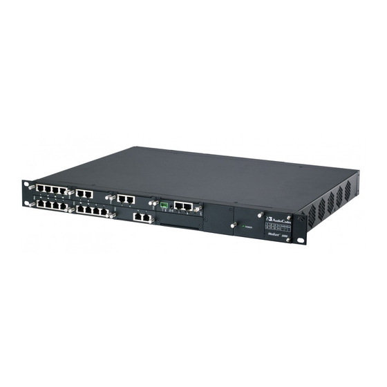
SIP User's Manual 1. Overview Overview This section provides an overview of the Mediant 1000 and Mediant 600 media gateways. Mediant 600 The Mediant 600 (hereafter referred to as device) is a cost-effective, wireline Voice-over-IP (VoIP) Session Initiation Protocol (SIP)-based media gateway. It is designed to interface between Time-Division Multiplexing (TDM) and IP networks in enterprises, small and medium businesses (SMB), and CPE application service providers. -
Page 22: Mediant 1000
Mediant 600 & Mediant 1000 The device provides a variety of management and provisioning tools, including an HTTP- based embedded Web server, Telnet, Element Management System (EMS), and Simple Network Management Protocol (SNMP). The user-friendly, Web interface provides remote configuration using a Web browser (such as Microsoft™ Internet Explorer™). - Page 23 SIP User's Manual 1. Overview Analog: The device's analog interface supports up to 24 analog ports (four ports per analog module) in various Foreign Exchange Office (FXO) or Foreign Exchange Station (FXS) configurations, supporting up to 24 simultaneous VoIP calls. The device supports up to six analog modules, each module providing four analog RJ-11 ports.
-
Page 24: Sip Overview
Mediant 600 & Mediant 1000 SIP Overview Session Initiation Protocol (SIP) is an application-layer control (signaling) protocol used on the gateway for creating, modifying, and terminating sessions with one or more participants. These sessions can include Internet telephone calls, media announcements, and conferences. -
Page 25: Configuration Concepts
Note: To initialize the device by assigning it an IP address, a firmware file (cmp), and a configuration file (ini file), you can use AudioCodes' BootP/TFTP utility, which accesses the device using the device's MAC address (refer to the Product Reference Manual). - Page 26 Mediant 600 & Mediant 1000 Reader's Notes SIP User's Manual Document #: LTRT-83308...
-
Page 27: Web-Based Management
SIP User's Manual 3. Web-Based Management Web-Based Management The device's Embedded Web Server (Web interface) provides FCAPS (fault management, configuration, accounting, performance, and security) functionality. The Web interface allows you to remotely configure your device for quick-and-easy deployment, including uploading of software (*.cmp), configuration (*.ini), and auxiliary files, and resetting the device. -
Page 28: Accessing The Web Interface
Mediant 600 & Mediant 1000 3.1.2 Accessing the Web Interface The Web interface can be opened using any standard Web browser (see ''Computer Requirements'' on page 27). When initially accessing the Web interface, use the default user name ('Admin') and password ('Admin'). For changing the login user name and password, see ''Configuring the Web User Accounts'' on page 66). -
Page 29: Areas Of The Gui
SIP User's Manual 3. Web-Based Management Note: If access to the device's Web interface is denied ("Unauthorized") due to Microsoft Internet Explorer security settings, perform the following: Delete all cookies in the Temporary Internet Files folder. If this does not resolve the problem, the security settings may need to be altered (continue with Step 2). -
Page 30: Toolbar
Mediant 600 & Mediant 1000 3.1.4 Toolbar The toolbar provides command buttons for quick-and-easy access to frequently required commands, as described in the table below: Table 3-1: Description of Toolbar Buttons Icon Button Description Name Submit Applies parameter settings to the device (see ''Saving Configuration'' on page 197). -
Page 31: Navigation Tree
SIP User's Manual 3. Web-Based Management 3.1.5 Navigation Tree The Navigation tree, located in the Navigation pane, displays the menus (pertaining to the menu tab selected on the Navigation bar) used for accessing the configuration pages. The Navigation tree displays a tree-like structure of menus. You can easily drill-down to the required page item level to open its corresponding page in the Work pane. -
Page 32: Displaying Navigation Tree In Basic And Full View
Mediant 600 & Mediant 1000 3.1.5.1 Displaying Navigation Tree in Basic and Full View You can view an expanded or reduced Navigation tree display regarding the number of listed menus and submenus. This is relevant when using the configuration tabs (Configuration, Maintenance, and Status &... -
Page 33: Showing / Hiding The Navigation Pane
SIP User's Manual 3. Web-Based Management 3.1.5.2 Showing / Hiding the Navigation Pane The Navigation pane can be hidden to provide more space for elements displayed in the Work pane. This is especially useful when the Work pane displays a page with a table that's wider than the Work pane and to view the all the columns, you need to use scroll bars. -
Page 34: Working With Configuration Pages
Mediant 600 & Mediant 1000 3.1.6 Working with Configuration Pages The configuration pages contain the parameters for configuring the device. The configuration pages are displayed in the Work pane, which is located to the right of the Navigation pane. 3.1.6.1... -
Page 35: Figure 3-7: Toggling Between Basic And Advanced View
SIP User's Manual 3. Web-Based Management 3.1.6.2.1 Displaying Basic and Advanced Parameters Some pages provide you with an Advanced Parameter List / Basic Parameter List toggle button that allows you to show or hide advanced parameters (in addition to displaying the basic parameters). This button is located on the top-right corner of the page and has two states: ... -
Page 36: Modifying And Saving Parameters
Mediant 600 & Mediant 1000 3.1.6.2.2 Showing / Hiding Parameter Groups Some pages provide groups of parameters, which can be hidden or shown. To toggle between hiding and showing a group, simply click the group name button that appears above each group. The button appears with a down-pointing or up-pointing arrow, indicating that it can be collapsed or expanded when clicked, respectively. -
Page 37: Entering Phone Numbers
SIP User's Manual 3. Web-Based Management Notes: • Parameters saved to the volatile memory (by clicking Submit), revert to their previous settings after a hardware or software reset (or if the device is powered down). Therefore, to ensure parameter changes (whether on- the-fly or not) are retained, you need to save ('burn') them to the device's non-volatile memory, i.e., flash (see ''Saving Configuration'' on page 197). -
Page 38: Working With Tables
Mediant 600 & Mediant 1000 3.1.6.5 Working with Tables The Web interface includes many configuration pages that provide tables for configuring the device. Some of these tables provide the following command buttons: Add Index: adds an index entry to the table. -
Page 39: Searching For Configuration Parameters
SIP User's Manual 3. Web-Based Management To organize the index entries in ascending, consecutive order: Click Compact; the index entries are organized in ascending, consecutive order, starting from index 0. For example, if you added three index entries 0, 4, and 6, then the index entry 4 is re-assigned index number 1 and the index entry 6 is re-assigned index number 2. -
Page 40: Working With Scenarios
Mediant 600 & Mediant 1000 Each searched result displays the following: • ini file parameter name • Link (in green) to its location (page) in the Web interface • Brief description of the parameter In the searched list, click the required parameter (link in green) to open the page in which the parameter appears;... -
Page 41: Creating A Scenario
SIP User's Manual 3. Web-Based Management 3.1.8.1 Creating a Scenario The Web interface allows you to create one Scenario with up to 20 configuration pages, as described in the procedure below: To create a Scenario: On the Navigation bar, click the Scenarios tab; a message box appears, requesting you to confirm creation of a Scenario: Figure 3-14: Scenario Creation Confirm Message Box Note: If a Scenario already exists, the Scenario Loading message box appears. -
Page 42: Accessing A Scenario
Mediant 600 & Mediant 1000 Repeat steps 5 through 8 to add additional Steps (i.e., pages). When you have added all the required Steps for your Scenario, click the Save & Finish button located at the bottom of the Navigation tree; a message box appears informing you that the Scenario has been successfully created. -
Page 43: Figure 3-17: Scenario Example
SIP User's Manual 3. Web-Based Management Click OK; the Scenario and its Steps appear in the Navigation tree, as shown in the example figure below: Figure 3-17: Scenario Example When you select a Scenario Step, the corresponding page is displayed in the Work pane. In each page, the available parameters are indicated by a dark-blue background;... -
Page 44: Editing A Scenario
Mediant 600 & Mediant 1000 3.1.8.3 Editing a Scenario You can modify a Scenario anytime by adding or removing Steps (i.e., pages) or parameters, and changing the Scenario name and the Steps' names. Note: Only users with access level of 'Security Administrator' can edit a Scenario. -
Page 45: Saving A Scenario To A Pc
SIP User's Manual 3. Web-Based Management 3.1.8.4 Saving a Scenario to a PC You can save a Scenario to a PC (as a dat file). This is especially useful when requiring more than one Scenario to represent different environment setups (e.g., where one includes PBX interoperability and another not). -
Page 46: Loading A Scenario To The Device
Mediant 600 & Mediant 1000 3.1.8.5 Loading a Scenario to the Device Instead of creating a Scenario, you can load a Scenario file (data file) from your PC to the device. To load a Scenario to the device: On the Navigation bar, click the Scenarios tab; the Scenario appears in the Navigation tree. -
Page 47: Exiting Scenario Mode
SIP User's Manual 3. Web-Based Management Click the Delete Scenario File button; a message box appears requesting confirmation for deletion. Figure 3-20: Message Box for Confirming Scenario Deletion Click OK; the Scenario is deleted and the Scenario mode closes. Note: You can also delete a Scenario using the following alternative methods: •... -
Page 48: Creating A Login Welcome Message
Mediant 600 & Mediant 1000 3.1.9 Creating a Login Welcome Message You can create a Welcome message box (alert message) that appears after each successful login to the device's Web interface. The ini file table parameter WelcomeMessage allows you to create the Welcome message. Up to 20 lines of character strings can be defined for the message. -
Page 49: 3.1.10 Getting Help
SIP User's Manual 3. Web-Based Management 3.1.10 Getting Help The Web interface provides you with context-sensitive Online Help. The Online Help provides you with brief descriptions of most of the parameters you'll need to successfully configure the device. The Online Help provides descriptions of parameters pertaining to the currently opened page. -
Page 50: 3.1.11 Logging Off The Web Interface
Mediant 600 & Mediant 1000 3.1.11 Logging Off the Web Interface You can log off the Web interface and re-access it with a different user account. For detailed information on the Web User Accounts, see User Accounts. To log off the Web interface: On the toolbar, click the Log Off button;... -
Page 51: Using The Home Page
To access the Home page: On the toolbar, click the Home icon; the 'Home' page is displayed. Figure 3-26: Mediant 600 Home Page Figure 3-27: Mediant 1000 Home Page Note: The displayed number and type of telephony interface modules depends on the device's hardware configuration. -
Page 52: Table 3-3: Description Of The Areas Of The Home Page
Mediant 600 & Mediant 1000 Protocol Type: signaling protocol currently used by the device (i.e. SIP) Gateway Operational State: operational state of the device: • LOCKED - device is locked (i.e. no new calls are accepted) • UNLOCKED - device is not locked •... - Page 53 SIP User's Manual 3. Web-Based Management Item # Description Dry Contact (normally open) status icon (green): Dry Contact is open (normal) (red): Dry contact is closed Dry Contact (normally closed) status icon: (green): Dry Contact is closed (normal) ...
-
Page 54: Assigning A Port Name
Mediant 600 & Mediant 1000 3.2.1 Assigning a Port Name The 'Home' page allows you to assign an arbitrary name or a brief description to each port. This description appears as a tooltip when you move your mouse over the port. -
Page 55: Viewing Analog Port Information
SIP User's Manual 3. Web-Based Management 3.2.3 Viewing Analog Port Information The 'Home' page allows you to view detailed information on a specific FXS or FXO analog port such as RTP/RTCP and voice settings. To view detailed port information: Click the port for which you want to view port settings;... -
Page 56: Replacing Modules
Mediant 600 & Mediant 1000 Table 3-4: Color-Coding Status for Trunk Channels Icon Color Label Description Light blue Inactive Configured, but currently no call Green Active Call in progress (RTP traffic) Purple Configured for SS7 (Currently not supported) Grey Non Voice... -
Page 57: Figure 3-34: Remove Module Button
SIP User's Manual 3. Web-Based Management To replace a module: Remove the module by performing the following: In the 'Home' page, click the title of the module that you want to replace; the Remove Module button appears: Figure 3-34: Remove Module Button Click the Remove Module button;... -
Page 58: Configuration Tab
Mediant 600 & Mediant 1000 Configuration Tab The Configuration tab on the Navigation bar displays menus in the Navigation tree related to device configuration. This tab provides the following main menus: System (see ''System Settings'' on page 58) ... -
Page 59: Configuring Nfs Settings
SIP User's Manual 3. Web-Based Management Configure the parameters as required. For configuring NFS, under the 'NFS Settings' group, click the NFS Table button; the 'NFS Settings' page appears. For a description of configuring this page, see ''Configuring NFS Settings'' on page 59. Click the Submit button to save your changes. -
Page 60: Configuring Syslog Settings
Mediant 600 & Mediant 1000 Table 3-5: NFS Settings Parameters Parameter Description Index The row index of the remote file system. The valid range is 1 to 16. Host Or IP The domain name or IP address of the NFS server. If a domain name is provided, a DNS server must be configured. -
Page 61: Configuring Regional Settings
SIP User's Manual 3. Web-Based Management To configure the Syslog client: Open the 'Syslog Settings' page (Configuration tab > System menu > Syslog Settings). Figure 3-40: Syslog Settings Page Configure the parameters as required, and then click the Submit button to apply your changes. -
Page 62: Configuring Certificates
Mediant 600 & Mediant 1000 Notes: • If the device is configured to obtain the date and time from an SNTP server (see ''Configuring Application Settings'' on page 58), the fields on this page are read-only and cannot be modified. -
Page 63: Figure 3-42: Certificates Signing Request Page
SIP User's Manual 3. Web-Based Management Open the ‘Certificates Signing Request' page (Configuration tab > System menu > Certificates). Figure 3-42: Certificates Signing Request Page In the 'Subject Name' field, enter the DNS name, and then click Generate CSR. A textual certificate signing request that contains the SSL device identifier is displayed. -
Page 64: Figure 3-43: Ike Table Listing Loaded Certificate Files
Mediant 600 & Mediant 1000 Notes: • The certificate replacement process can be repeated when necessary (e.g., the new certificate expires). • It is possible to use the IP address of the device (e.g., 10.3.3.1) instead of a qualified DNS name in the Subject Name. This is not recommended since the IP address is subject to changes and may not uniquely identify the device. - Page 65 SIP User's Manual 3. Web-Based Management To enable two-way client certificates: Set the parameter 'Secured Web Connection (HTTPS)' to 'HTTPS Only' (0) in ''Configuring Web Security Settings'' on page to ensure you have a method of accessing the device in case the client certificate doesn’t work. Restore the previous setting after testing the configuration.
-
Page 66: Management Settings
Mediant 600 & Mediant 1000 In the 'Subject Name' field, enter the fully-qualified DNS name (FQDN) as the certificate subject, and then click Generate Self-signed; after a few seconds, a message appears displaying the new subject name. Save configuration (see ''Saving Configuration'' on page 197), and then restart the device for the new certificate to take effect. -
Page 67: Figure 3-44: Web User Accounts Page (For Users With 'Security Administrator' Privileges)
SIP User's Manual 3. Web-Based Management The default attributes for the two Web user accounts are shown in the following table: Table 3-7: Default Attributes for the Web User Accounts Account / Attribute User Name Password Access Level (Case-Sensitive) (Case-Sensitive) Primary Account Admin Admin... - Page 68 Mediant 600 & Mediant 1000 Notes: • The access level of the primary Web user account is 'Security Administrator', which cannot be modified. • The access level of the secondary account can only be modified by the primary account user or a secondary account user with 'Security Administrator' access level.
-
Page 69: Figure 3-45: Web Security Settings Page
SIP User's Manual 3. Web-Based Management 3.3.1.6.2 Configuring Web Security Settings The 'WEB Security Settings' page is used to define a secure Web access communication method. For a description of these parameters, see ''Web and Telnet Parameters'' on page 513. ... -
Page 70: Figure 3-47: Web & Telnet Access List Page - Add New Entry
Mediant 600 & Mediant 1000 3.3.1.6.4 Configuring Web and Telnet Access List The 'Web & Telnet Access List' page is used to define IP addresses (up to ten) that are permitted to access the device's Web, Telnet, and SSH interfaces. Access from an undefined IP address is denied. -
Page 71: Figure 3-49: Radius Parameters Page
SIP User's Manual 3. Web-Based Management 3.3.1.6.5 Configuring RADIUS Settings The 'RADIUS Settings' page is used for configuring the Remote Authentication Dial In User Service (RADIUS) accounting parameters. For a description of these parameters, see ''Configuration Parameters Reference'' on page 501. ... -
Page 72: Figure 3-50: Radius Parameters Page
Mediant 600 & Mediant 1000 To configure the SNMP community strings: Open the 'SNMP Community String' page (Maintenance tab > System menu > Management submenu > SNMP submenu > SNMP Community String). Figure 3-50: RADIUS Parameters Page Configure the SNMP community strings parameters according to the table below. -
Page 73: Figure 3-51: Snmp Trap Destinations Page
SIP User's Manual 3. Web-Based Management 3.3.1.6.6.2 Configuring SNMP Trap Destinations The 'SNMP Trap Destinations' page allows you to configure up to five SNMP trap managers. To configure SNMP trap destinations: Open the 'SNMP Trap Destinations' page (Maintenance tab > System menu > Management submenu >... -
Page 74: Figure 3-52: Snmp Trusted Managers
Mediant 600 & Mediant 1000 3.3.1.6.6.3 Configuring SNMP Trusted Managers The 'SNMP Trusted Managers' page allows you to configure up to five SNMP Trusted Managers, based on IP addresses. By default, the SNMP agent accepts SNMP Get and Set requests from any IP address, as long as the correct community string is used in the request. -
Page 75: Table 3-10: Snmp V3 Users Parameters
SIP User's Manual 3. Web-Based Management Notes: • For a description of the web interface's table command buttons (e.g., Duplicate and Delete), see ''Working with Tables'' on page 38. • You can also configure SNMP v3 users using the ini file table parameter SNMPUsers (see ''SNMP Parameters'' on page 534). -
Page 76: Voip Settings
Mediant 600 & Mediant 1000 3.3.2 VoIP Settings The VoIP menu includes the following main submenus: Network (see ''Network'' on page 76) TDM (see TDM on page 87) Security (see ''Security'' on page 88) PSTN (see PSTN on page 96) ... -
Page 77: Figure 3-54: Ip Settings Page
SIP User's Manual 3. Web-Based Management Notes: • For a detailed description and examples of network interfaces configuration, see ''Network Configuration'' on page 404. • When adding more than one interface, ensure that you enable VLANs using the 'VLAN Mode' (VlANMode) parameter. •... -
Page 78: Figure 3-55: Confirmation Message For Accessing The Multiple Interface Table
Mediant 600 & Mediant 1000 Under the 'Multiple Interface Settings' group, click the Multiple Interface Table button; a confirmation message box appears: Figure 3-55: Confirmation Message for Accessing the Multiple Interface Table Click OK to confirm; the 'Multiple Interface Table' page appears:... - Page 79 SIP User's Manual 3. Web-Based Management Parameter Description are allowed on the interface. [4] OAMP + Control = Only OAMP and Call Control applications are allowed on the interface. [5] Media + Control = Only Media and Call Control applications are allowed on the interface.
-
Page 80: Mediant 600 & Mediant
Mediant 600 & Mediant 1000 Parameter Description For IPv4 Interfaces, the prefix length values range from 0 to Note: Subnets of different interfaces must not overlap in any way (e.g., defining two interfaces with 10.0.0.1/8 and 10.50.10.1/24 is invalid). Each interface must have its own address space. -
Page 81: Figure 3-57: Ip Routing Table Page
SIP User's Manual 3. Web-Based Management To configure static IP routing: Open the 'IP Routing Table' page (Configuration tab > VoIP menu > Network submenu > IP Routing Table). Figure 3-57: IP Routing Table Page In the 'Add a new table entry' table, add a new static routing rule according to the parameters described in the table below. - Page 82 Mediant 600 & Mediant 1000 Parameter Description Gateway IP Address The IP address of the router (next hop) to which the packets [StaticRouteTable_Gateway] are sent if their destination matches the rules in the adjacent columns. Note: The Gateway address must be in the same subnet as the IP address of the interface over which you configure this static routing rule.
-
Page 83: Figure 3-58: Qos Settings Page
SIP User's Manual 3. Web-Based Management To configure QoS: Open the 'QoS Settings' page (Configuration tab > VoIP menu > Network submenu > QoS Settings). Figure 3-58: QoS Settings Page Configure the QoS parameters as required. Click the Submit button to save your changes. Save the changes to flash memory (see ''Saving Configuration'' on page 197). -
Page 84: Figure 3-59: Dns Settings Page
Mediant 600 & Mediant 1000 3.3.2.1.4 DNS The DNS submenu includes the following items: DNS Settings (refer to ''Configuring DNS Settings'' on page 84) Internal DNS Table (refer to ''Configuring the Internal DNS Table'' on page 85) ... -
Page 85: Figure 3-60: Internal Dns Table Page
SIP User's Manual 3. Web-Based Management 3.3.2.1.4.2 Configuring the Internal DNS Table The 'Internal DNS Table' page, similar to a DNS resolution translates up to 20 host (domain) names into IP addresses (e.g., when using the 'Outbound IP Routing Table' for Tel-to-IP call routing). -
Page 86: Figure 3-61: Internal Srv Table Page
Mediant 600 & Mediant 1000 3.3.2.1.4.3 Configuring the Internal SRV Table The 'Internal SRV Table' page resolves host names to DNS A-Records. Three different A- Records can be assigned to each host name. Each A-Record contains the host name, priority, weight, and port. -
Page 87: Tdm
SIP User's Manual 3. Web-Based Management 3.3.2.2 The TDM submenu contains the following item: TDM (see ''Configuring TDM Bus Settings'' on page 87) 3.3.2.2.1 Configuring TDM Bus Settings The 'TDM Bus Settings' page allows you to configure the device's Time-Division Multiplexing (TDM) bus settings. -
Page 88: Security
Mediant 600 & Mediant 1000 3.3.2.3 Security The Security Settings submenu allows you to configure various security settings. This menu contains the following page items: Firewall Settings (see ''Configuring Firewall Settings'' on page 88) General Security Settings (see ''Configuring General Security Settings'' on page 92) ... -
Page 89: Figure 3-63: Firewall Settings Page
SIP User's Manual 3. Web-Based Management To add firewall rules: Open the 'Firewall Settings' page (Configuration tab > VoIP menu > Security submenu > Firewall Settings). Figure 3-63: Firewall Settings Page In the 'Add' field, enter the index of the access rule that you want to add, and then click Add;... -
Page 90: Table 3-13: Internal Firewall Parameters
Mediant 600 & Mediant 1000 To delete a rule: Select the radio button of the entry you want to activate. Click the Delete Rule button; the rule is deleted. To save the changes to flash memory, see ''Saving Configuration'' on page 197. - Page 91 SIP User's Manual 3. Web-Based Management Parameter Description Packet Size Maximum allowed packet size. [AccessList_Packet_Size] The valid range is 0 to 65535. Note: When filtering fragmented IP packets, this field relates to the overall (re-assembled) packet size, and not to the size of each fragment.
-
Page 92: Figure 3-64: General Security Settings Page
Mediant 600 & Mediant 1000 3.3.2.3.2 Configuring General Security Settings The 'General Security Settings' page is used to configure various security features. For a description of the parameters appearing on this page, refer ''Configuration Parameters Reference'' on page 501. ... -
Page 93: Figure 3-65: Ip Security Proposals Table
SIP User's Manual 3. Web-Based Management To configure IP Security Proposals: Open the ‘IP Security Proposals Table’ page (Configuration tab > VoIP menu > Security submenu > IPSec Proposal Table). Figure 3-65: IP Security Proposals Table In the figure above, four proposals are defined. Select an Index, click Edit, and then modify the proposal as required. -
Page 94: Figure 3-66: Ip Security Associations Table Page
Mediant 600 & Mediant 1000 3.3.2.3.4 Configuring IP Security Associations Table The 'IP Security Associations Table' page allows you to configure up to 20 peers (hosts or networks) for IP security (IPSec)/IKE. Each of the entries in the IPSec Security Association... - Page 95 SIP User's Manual 3. Web-Based Management Parameter Name Description Authentication Method Selects the method used for peer authentication during IKE [IPsecSATable_AuthenticationMetho main mode. [0] Pre-shared Key (default) [1] RSA Signature = in X.509 certificate Note: For RSA-based authentication, both peers must be provisioned with certificates signed by a common CA.
-
Page 96: Pstn
Mediant 600 & Mediant 1000 Parameter Name Description IPSec SA Lifetime (Kbs) Determines the maximum volume of traffic (in kilobytes) for [IPsecSATable_Phase2SaLifetimeInK which the negotiated IPSec SA (Quick mode) is valid. After this specified volume is reached, the SA is re-negotiated. -
Page 97: Figure 3-67: Cas State Machine Page
SIP User's Manual 3. Web-Based Management 3.3.2.4.1 Configuring CAS State Machines The 'CAS State Machine' page allows you to modify various timers and other basic parameters to define the initialization of the CAS state machine without changing the state machine itself (no compilation is required). The change doesn't affect the state machine itself, but rather the configuration. -
Page 98: Table 3-17: Cas State Machine Parameters Description
Mediant 600 & Mediant 1000 Table 3-17: CAS State Machine Parameters Description Parameter Description Generate Digit On Time Generates digit on-time (in msec). [CasStateMachineGenerateDigitOnTime] The value must be a positive value. The default value is -1 (use value from CAS state machine). -
Page 99: Figure 3-68: Trunk Settings Page
SIP User's Manual 3. Web-Based Management 3.3.2.4.2 Configuring Trunk Settings The 'Trunk Settings' page allows you to configure the device's trunks. This includes selecting the PSTN protocol and configuring related parameters. Some parameters can be configured when the trunk is in service, while others require you to take the trunk out of service (by clicking the Stop button). -
Page 100: Figure 3-69: Trunk Scroll Bar (Used Only As An Example)
Mediant 600 & Mediant 1000 On the top of the page, a bar with Trunk number icons displays the status of each trunk, according to the following color codes: • Grey: Disabled • Green: Active • Yellow: RAI alarm (also appears when you deactivate a Trunk by clicking the Deactivate button) •... - Page 101 SIP User's Manual 3. Web-Based Management Click the Apply Trunk Settings button to apply the changes to the selected trunk (or click Apply to All Trunks to apply the changes to all trunks); the Stop Trunk button replaces Apply Trunk Settings and the ‘Trunk Configuration State’ displays 'Active'. To save the changes to flash memory, see ''Saving Configuration'' on page 197.
-
Page 102: Media
Mediant 600 & Mediant 1000 3.3.2.5 Media The Media submenu allows you to configure the device's channel parameters and contains the following items: Voice Settings (see ''Configuring Voice Settings'' on page 102) Fax/Modem/CID Settings (see Configuring Fax/Modem/CID Settings on page 103) ... -
Page 103: Figure 3-71: Fax/Modem/Cid Settings Page
SIP User's Manual 3. Web-Based Management 3.3.2.5.2 Configuring Fax/Modem/CID Settings The 'Fax/Modem/CID Settings' page is used for configuring fax, modem, and Caller ID (CID) parameters. For a detailed description of the parameters appearing on this page, see ''Configuration Parameters Reference'' on page 501. ... -
Page 104: Figure 3-72: Rtp/Rtcp Settings Page
Mediant 600 & Mediant 1000 3.3.2.5.3 Configuring RTP/RTCP Settings The 'RTP/RTCP Settings' page configures the Real-Time Transport Protocol (RTP) and Real-Time Transport (RTP) Control Protocol (RTCP) parameters. For a detailed description of the parameters appearing on this page, refer to ''Configuration Parameters Reference'' on page 501. -
Page 105: Figure 3-73: 'Ipmedia Settings Page
SIP User's Manual 3. Web-Based Management 3.3.2.5.4 Configuring IP Media Settings The 'IPMedia Settings' page allows you to configure the IP media parameters. For a detailed description of the parameters appearing on this page, see ''Configuration Parameters Reference'' on page 501. ... -
Page 106: Figure 3-74: General Media Settings
Mediant 600 & Mediant 1000 3.3.2.5.5 Configuring General Media Settings The 'General Media Settings' page allows you to configure various media parameters. For a detailed description of the parameters appearing on this page, see ''Configuration Parameters Reference'' on page 501. -
Page 107: Figure 3-76: Sip Media Realm Table Page
SIP User's Manual 3. Web-Based Management 3.3.2.5.7 Configuring Media Realms The 'SIP Media Realm Table' page allows you to define a pool of up to 64 SIP media interfaces, termed Media Realms. This table allows you to divide a Media-type interface (defined in the 'Multiple Interface' table - see ''Configuring IP Interface Settings'' on page 76) into several realms, where each realm is specified by a UDP port range. - Page 108 Mediant 600 & Mediant 1000 Parameter Description IPv4 Interface Name Associates the IPv4 interface to the Media Realm. [CpMediaRealm_IPv4IF] Note: The name of this interface must be exactly (i.e., case- sensitive etc.) as configured in the 'Multiple Interface' table (InterfaceTable parameter). For the VoIP WAN IP address, you must enter the string "WAN"...
-
Page 109: Services
SIP User's Manual 3. Web-Based Management 3.3.2.5.8 Configuring Media Security The 'Media Security' page allows you to configure media security. For a detailed description of the parameters appearing on this page, see ''Configuration Parameters Reference'' on page 501. To configure media security: Open the 'Media Security' page (Configuration tab >... -
Page 110: Applications Enabling
Mediant 600 & Mediant 1000 To configure the LDAP parameters: Open the 'LDAP Settings' page (Configuration tab > VoIP menu > Services submenu >LDAP Settings). Figure 3-78: LDAP Settings Page The read-only 'LDAP Server Status' field displays one of the following possibilities: •... -
Page 111: Control Network
SIP User's Manual 3. Web-Based Management To enable an application: Open the 'Applications Enabling' page (Configuration tab > VoIP menu > Applications Enabling submenu > Applications Enabling). Figure 3-79: Applications Enabling Page Save the changes to the device's flash memory and then reset the device (see ''Saving Configuration'' on page 197). -
Page 112: Figure 3-80: Srd Settings Page
Mediant 600 & Mediant 1000 Notes: • For a detailed description of SRD's, see ''Multiple SIP Signaling/Media Interfaces Environment'' on page 261. • The SRD table can also be configured using the ini file table parameter SRD. To configure SRDs: Open the 'SRD Settings' page (Configuration tab >... -
Page 113: Table 3-19: Srd Table Parameters
SIP User's Manual 3. Web-Based Management Table 3-19: SRD Table Parameters Parameter Description SRD Name Mandatory descriptive name of the SRD. [SRD_Name] The valid value can be a string of up to 21 characters. Media Realm Determines the media ports associated with the specific SRD. This is the name as defined in the 'SIP Media Realm' table (CpMediaRealm). -
Page 114: Figure 3-81: Sip Interface Table Page
Mediant 600 & Mediant 1000 To configure the SIP Interface table: Open the 'SIP Interface Table' page (Configuration tab > VoIP menu > Control Network submenu > SIP Interface Table). Figure 3-81: SIP Interface Table Page Add an entry and then configure it according to the table below. - Page 115 SIP User's Manual 3. Web-Based Management 3.3.2.8.3 Configuring IP Groups The 'IP Group Table' page allows you to create up to 32 logical IP entities called IP Groups. An IP Group is an entity with a set of definitions such as a Proxy Set ID (see ''Configuring Proxy Sets Table'' on page 120), which represents the IP address of the IP Group.
-
Page 116: Figure 3-82: Ip Group Table Page
Mediant 600 & Mediant 1000 To configure IP Groups: Open the 'IP Group Table' page (Configuration tab > VoIP menu > Control Network submenu > IP Group Table). Figure 3-82: IP Group Table Page Configure the IP group parameters according to the table below. - Page 117 SIP User's Manual 3. Web-Based Management Parameter Description forwards these responses directly to the SIP users. To route a call to a registered user, a rule must be configured in the ‘Outbound IP Routing Table’ table (see Configuring the Outbound IP Routing Table). The device searches the dynamic database (by using the request URI) for an entry that matches a registered AOR or Contact.
- Page 118 Mediant 600 & Mediant 1000 Parameter Description The SRD (defined in Configuring SRD Table on page 111) [IPGroup_SRD] associated with the IP Group. The default is 0. Note: For this parameter to take effect, a device reset is required. Media Realm...
- Page 119 SIP User's Manual 3. Web-Based Management Parameter Description SIP Re-Routing Mode Determines the routing mode after a call redirection (i.e., a 3xx [IPGroup_SIPReRoutingMode] SIP response is received) or transfer (i.e., a SIP REFER request is received). [0] Standard = INVITE messages that are generated as a result of Transfer or Redirect are sent directly to the URI, according to the Refer-To header in the REFER message or Contact header in the 3xx response (default).
- Page 120 Mediant 600 & Mediant 1000 Parameter Description Serving IP Group ID If configured, INVITE messages initiated from the IP Group are [IPGroup_ServingIPGroup] sent to this Serving IP Group (range 1 to 9). In other words, the INVITEs are sent to the address defined for the Proxy Set associated with this Serving IP Group.
-
Page 121: Figure 3-83: Proxy Sets Table Page
SIP User's Manual 3. Web-Based Management To add Proxy servers: Open the 'Proxy Sets Table' page (Configuration tab > VoIP menu > Control Network submenu > Proxy Sets Table). Figure 3-83: Proxy Sets Table Page From the 'Proxy Set ID' drop-down list, select an ID for the desired group. Configure the Proxy parameters according to the following table. - Page 122 Mediant 600 & Mediant 1000 Parameter Description message is sent according to the following preferences: To the Trunk Group's Serving IP Group ID, as defined in the 'Trunk Group Settings' table. According to the 'Outbound IP Routing Table' if the parameter PreferRouteTable is set to 1.
- Page 123 SIP User's Manual 3. Web-Based Management Parameter Description SIP OPTIONS messages. [2] Using Register = Enables Keep-Alive with Proxy using SIP REGISTER messages. If set to 'Using Options', the SIP OPTIONS message is sent every user-defined interval (configured by the parameter ProxyKeepAliveTime).
- Page 124 Mediant 600 & Mediant 1000 Parameter Description in the list occurs, all load statistics are erased and balancing starts over again. When the Random Weights algorithm is used, the outgoing requests are not distributed equally among the Proxies. The weights are received from the DNS server by using SRV records.
-
Page 125: Sip Definitions
SIP User's Manual 3. Web-Based Management 3.3.2.9 SIP Definitions The SIP Definitions submenu allows you to configure various SIP call control settings. This menu contains the following page items: General Parameters (see ''Configuring SIP General Parameters'' on page 125) ... -
Page 126: Figure 3-84: Sip General Parameters Page
Mediant 600 & Mediant 1000 Figure 3-84: SIP General Parameters Page Configure the parameters as required. Click the Submit button to save your changes. To save the changes to flash memory, see ''Saving Configuration'' on page 197. SIP User's Manual... -
Page 127: Figure 3-85: Advanced Parameters Page
SIP User's Manual 3. Web-Based Management 3.3.2.9.2 Configuring Advanced Parameters The 'Advanced Parameters' page allows you to configure advanced SIP control parameters. For a description of the parameters appearing on this page, see ''Configuration Parameters Reference'' on page 501. To configure advanced general protocol parameters: Open the 'Advanced Parameters' page (Configuration tab >... -
Page 128: Figure 3-86: Account Table Page
Mediant 600 & Mediant 1000 3.3.2.9.3 Configuring Account Table The 'Account Table' page allows you to define up to 32 Accounts per Trunk Group (Served Trunk Group) or source IP Group (Served IP Group) for registration and/or digest authentication (user name and password) to a destination IP address (Serving IP Group). - Page 129 SIP User's Manual 3. Web-Based Management Parameter Description Group from where the call originated. For IP-to-Tel calls, the Served Trunk Group is the 'Trunk Group ID' defined in the 'Inbound IP Routing Table' (see ''Configuring the Inbound IP Routing Table'' on page 165).
- Page 130 Mediant 600 & Mediant 1000 Parameter Description Register Enables registration. [Account_Register] [0] No = Don't register [1] Yes = Enables registration When enabled, the device sends REGISTER requests to the Serving IP Group. In addition, to activate registration, you also need to set the parameter 'Registration Mode' to 'Per Account' in the 'Trunk Group Settings' table for the specific Trunk Group.
-
Page 131: Figure 3-87: Proxy & Registration Page
SIP User's Manual 3. Web-Based Management 3.3.2.9.4 Configuring Proxy and Registration Parameters The 'Proxy & Registration' page allows you to configure the Proxy server and registration parameters. For a description of the parameters appearing on this page, see ''Configuration Parameters Reference'' on page 501. Note: To view whether the device or its endpoints have registered to a SIP Registrar/Proxy server, see ''Viewing Registration Status'' on page 216. -
Page 132: 3.3.2.10 Coders And Profiles
Mediant 600 & Mediant 1000 To save the changes to flash memory, see ''Saving Configuration'' on page 197. Click the Proxy Set Table button to open the 'Proxy Sets Table' page to configure groups of proxy addresses. Alternatively, you can open this page from the Proxy Sets... -
Page 133: Figure 3-89: Coders Page
SIP User's Manual 3. Web-Based Management page 165) In addition, you can associate different Profiles per the channels. Notes: • The default values of the parameters in the 'Tel Profile Settings' and 'IP Profile Settings' pages are identical to their default values in their respective primary configuration page ("global"... - Page 134 Mediant 600 & Mediant 1000 In the 'Payload Type' field, if the payload type (i.e., format of the RTP payload) for the selected coder is dynamic, enter a value from 0 to 120 (payload types of 'well-known' coders cannot be modified).
-
Page 135: Figure 3-90: Coder Group Settings Page
SIP User's Manual 3. Web-Based Management To configure Coder Groups: Open the 'Coder Group Settings' page (Configuration tab > VoIP menu > Coders And Profiles submenu > Coders Group Settings). Figure 3-90: Coder Group Settings Page From the 'Coder Group ID' drop-down list, select a Coder Group ID. From the 'Coder Name' drop-down list, select the first coder for the Coder Group. -
Page 136: Figure 3-91: Tel Profile Settings Page
Mediant 600 & Mediant 1000 To configure Tel Profiles: Open the 'Tel Profile Settings' page (Configuration tab > VoIP menu > Coders And Profiles submenu > Tel Profile Settings). Figure 3-91: Tel Profile Settings Page From the 'Profile ID' drop-down list, select the Tel Profile identification number you want to configure. - Page 137 SIP User's Manual 3. Web-Based Management From the 'Profile Preference' drop-down list, select the priority of the Tel Profile, where '1' is the lowest priority and '20' is the highest. If both IP and Tel profiles apply to the same call, the coders and other common parameters (noted by an asterisk in the description of the parameter TelProfile) of the preferred Profile are applied to that call.
-
Page 138: Figure 3-92: Ip Profile Settings Page
Mediant 600 & Mediant 1000 To configure IP Profiles: Open the 'IP Profile Settings' page (Configuration tab > VoIP menu > Coders And Profiles submenu > IP Profile Settings). Figure 3-92: IP Profile Settings Page From the 'Profile ID' drop-down list, select an identification number for the IP Profile. -
Page 139: 3.3.2.11 Gw And Ip To Ip
SIP User's Manual 3. Web-Based Management From the 'Coder Group' drop-down list, select the coder group that you want to assign to the IP Profile. You can select the device's default coders (see ''Configuring Coders'' on page 133), or one of the coder groups you defined in the 'Coder Group Settings' page (see ''Configuring Coder Groups'' on page 134). -
Page 140: Figure 3-93: Trunk Group Table Page
Mediant 600 & Mediant 1000 To configure the Trunk Group Table: Open the 'Trunk Group Table' page (Configuration tab > VoIP menu > GW and IP to IP submenu > Trunk Group > Trunk Group). Figure 3-93: Trunk Group Table Page Configure the Trunk Group according to the table below. - Page 141 SIP User's Manual 3. Web-Based Management Parameter Description Phone Number The telephone number that is assigned to the channel. [TrunkGroup_FirstPhoneNumber] This value can include up to 50 characters. For a range of channels, enter only the first telephone number. Subsequent channels are assigned the next consecutive telephone number.
-
Page 142: Figure 3-94: Trunk Group Settings Page
Mediant 600 & Mediant 1000 3.3.2.11.1.2 Configuring Trunk Group Settings The 'Trunk Group Settings' page allows you to configure the settings of up to 24 Trunk Groups. These Trunk Groups are configured in the 'Trunk Group Table' page (see Configuring Trunk Group Table on page 139). -
Page 143: Table 3-25: Trunk Group Settings Parameters
SIP User's Manual 3. Web-Based Management Table 3-25: Trunk Group Settings Parameters Parameter Description Trunk Group ID The Trunk Group ID that you want to configure. [TrunkGroupSettings_TrunkGroupId] Channel Select Mode The method for which IP-to-Tel calls are assigned to channels pertaining to a Trunk Group. For a detailed [TrunkGroupSettings_ChannelSelectM ode] description of this parameter, refer to the global... - Page 144 Mediant 600 & Mediant 1000 Parameter Description Notes: To enable Trunk Group registrations, configure the global parameter IsRegisterNeeded to 1. This is unnecessary for 'Per Account' registration mode. If no mode is selected, the registration is performed according to the global registration parameter ChannelSelectMode.
-
Page 145: Figure 3-95: General Settings Page
SIP User's Manual 3. Web-Based Management 3.3.2.11.2 Manipulation The Manipulation Tables submenu allows you to configure number manipulation and mapping of NPI/TON to SIP messages. This submenu includes the following items: General Settings (see ''Configuring General Settings'' on page 145) ... - Page 146 Mediant 600 & Mediant 1000 3.3.2.11.2.2 Configuring Number Manipulation Tables The device provides number manipulation tables for incoming (IP-to-Tel) and outgoing (Tel-to-IP) calls. These tables are used to modify the destination and/or source telephone numbers so that the calls can be routed correctly. For example, telephone number manipulation can be implemented by the following: ...
-
Page 147: Figure 3-96: Source Phone Number Manipulation Table For Tel-To-Ip Calls
SIP User's Manual 3. Web-Based Management Notes: • Number manipulation can occur before or after a routing decision is made. For example, you can route a call to a specific Trunk Group according to its original number, and then you can remove or add a prefix to that number before it is routed. -
Page 148: Table 3-26: Number Manipulation Parameters Description
Mediant 600 & Mediant 1000 • Index 1: When the destination number has the prefix 03 (e.g., 035000), source number prefix 201 (e.g., 20155), and from source IP Group ID 2, the source number is changed to, for example, 97120155. - Page 149 SIP User's Manual 3. Web-Based Management Parameter Description The source IP address can include the asterisk (*) wildcard to represent any number between 0 and 255. For example, 10.8.8.* represents all IP addresses between 10.8.8.0 and 10.8.8.255. Web: Stripped Digits From Number of digits to remove from the left of the telephone number prefix.
-
Page 150: Figure 3-97: Redirect Number Ip To Tel Page
Mediant 600 & Mediant 1000 Parameter Description Notes: This field is applicable only to Number Manipulation tables for source number manipulation. If 'Presentation' is set to 'Restricted' and the AssertedIdMode parameter is set to 'P-Asserted', the From header in the INVITE message includes the following: From: 'anonymous' <sip:... -
Page 151: Table 3-27: Redirect Number Ip To Tel Parameters Description
SIP User's Manual 3. Web-Based Management Table 3-27: Redirect Number IP to Tel Parameters Description Parameter Description Web/EMS: Destination Destination (called) telephone number prefix. An asterisk (*) represents Prefix any number. Web/EMS: Redirect Prefix Redirect telephone number prefix. An asterisk (*) represents any number. -
Page 152: Figure 3-98: Redirect Number Tel To Ip Page
Mediant 600 & Mediant 1000 Parameter Description Web: NPI The Numbering Plan Indicator (NPI) assigned to this entry. EMS: Number Plan [0] Unknown (default) [9] Private [1] E.164 Public [-1] Not Configured = value received from PSTN/IP is used... -
Page 153: Table 3-28: Redirect Number Tel To Ip Parameters Description
SIP User's Manual 3. Web-Based Management Click the Submit button to save your changes. To save the changes to flash memory, see ''Saving Configuration'' on page 197. Table 3-28: Redirect Number Tel to IP Parameters Description Parameter Description Source Trunk Group The Trunk Group from where the Tel call is received. -
Page 154: Figure 3-99: Phone Context Table Page
Mediant 600 & Mediant 1000 3.3.2.11.2.5 Mapping NPI/TON to SIP Phone-Context The 'Phone-Context Table' page allows you to map Numbering Plan Indication (NPI) and Type of Number (TON) to the SIP Phone-Context parameter. When a call is received from the ISDN/Tel, the NPI and TON are compared against the table and the matching Phone- Context value is used in the outgoing SIP INVITE message. -
Page 155: Table 3-30: Npi/Ton Values For Isdn Etsi
SIP User's Manual 3. Web-Based Management Parameter Description Select the Number Plan assigned to this entry. [0] Unknown (default) [1] E.164 Public [9] Private For a detailed list of the available NPI/TON values, see Numbering Plans and Type of Number on page 155. Select the Type of Number assigned to this entry. - Page 156 Mediant 600 & Mediant 1000 Description Private [9] Unknown [0] A private number, but with no further information about the numbering plan. Level 2 Regional [1] Level 1 Regional [2] A private number with a location, e.g., 3932200. PISN Specific [3] Level 0 Regional (local) [4] A private local extension number, e.g., 2200.
-
Page 157: Figure 3-100: Release Cause Mapping Page
SIP User's Manual 3. Web-Based Management To configure Release Cause Mapping: Open the 'Release Cause Mapping' page (Configuration tab > VoIP menu > GW and IP to IP submenu > Manipulations submenu > Release Cause Mapping). Figure 3-100: Release Cause Mapping Page In the 'Release Cause Mapping from ISDN to SIP' group, map different Q.850 Release Causes to SIP Responses. -
Page 158: Figure 3-101: Routing General Parameters Page
Mediant 600 & Mediant 1000 3.3.2.11.3 Routing The Routing submenu allows you to configure call routing rules. This submenu includes the following page items: General Parameters (see ''Configuring General Routing Parameters'' on page 158) Tel to IP Routing (see ''Configuring Outbound IP Routing Table'' on page 159) ... - Page 159 SIP User's Manual 3. Web-Based Management 3.3.2.11.3.2 Configuring Outbound IP Routing Table The 'Outbound IP Routing Table' page allows you to configure up to 180 Tel-to- IP/outbound IP call routing rules. The device uses these rules to route calls (from the Tel or IP) to IP destinations.
-
Page 160: Figure 3-102: Locating Srd
Mediant 600 & Mediant 1000 Since each call must have a destination IP Group (even in cases when the destination type is not to an IP Group), in cases when the IP Group is not specified, the SRD's default IP Group is used (the first defined IP Group that belongs to the SRD). - Page 161 SIP User's Manual 3. Web-Based Management Assign IP Profiles: IP Profiles can be assigned to destination addresses (also when a proxy is used). Alternative Routing (when a proxy isn't used): An alternative IP destination can be configured for specific call. To associate an alternative IP address to a called telephone number prefix, assign it with an additional entry (with a different IP address), or use an FQDN that resolves into two IP addresses.
-
Page 162: Figure 3-103: Outbound Ip Routing Table Page
Mediant 600 & Mediant 1000 To configure outbound IP routing rules: Open the 'Outbound IP Routing Table' page (Configuration tab > VoIP menu > GW and IP to IP submenu > Routing submenu > Tel to IP Routing). Figure 3-103: Outbound IP Routing Table Page The figure above displays the following outbound IP routing rules: •... -
Page 163: Table 3-31: Outbound Ip Routing Table Parameters
SIP User's Manual 3. Web-Based Management Table 3-31: Outbound IP Routing Table Parameters Parameter Description Web/EMS: Tel to IP Determines whether to route received calls to an IP destination before or after Routing Mode manipulation of the destination number. [RouteModeTel2IP] ... - Page 164 Mediant 600 & Mediant 1000 Parameter Description All calls matching all or any combination of the above characteristics are sent to the IP destination defined below. Note: For alternative routing, additional entries of the same prefix can be configured. Web: Dest. IP...
- Page 165 SIP User's Manual 3. Web-Based Management Parameter Description Groups'' on page 115), then the Request-URI host name in the INVITE message is set to the value defined for the parameter 'Dest. IP Address' (above); otherwise, if no IP address is defined, it is set to the value of the parameter 'SIP Group Name' (defined in the 'IP Group' table).
-
Page 166: Figure 3-104: Inbound Ip Routing Table
Mediant 600 & Mediant 1000 Notes: • When a call release reason (defined in ''Configuring Reasons for Alternative Routing'' on page 168) is received for a specific IP-to-Tel call, an alternative Trunk Group for that call can be configured. This is done by configuring an additional routing rule for the same call characteristics, but with a different Trunk Group ID. - Page 167 SIP User's Manual 3. Web-Based Management Parameter Description [0] Route calls before manipulation = Incoming IP calls are routed before number manipulation (default). [1] Route calls after manipulation = Incoming IP calls are routed after number manipulation are applied. Dest.
- Page 168 Mediant 600 & Mediant 1000 Parameter Description Source IP Group ID For IP-to-Tel calls: The IP Group associated with the incoming IP call. This is the IP Group from where the INVITE message originated. This IP Group can later be used as the 'Serving IP Group' in the Account table for obtaining authentication user name/password for this call (see ''Configuring Account Table'' on page 128).
-
Page 169: Figure 3-105: Reasons For Alternative Routing Page
SIP User's Manual 3. Web-Based Management To configure reasons for alternative routing: Open the 'Reasons for Alternative Routing' page (Configuration tab > VoIP menu > GW and IP to IP submenu > Routing submenu > Alternative Routing Reasons). Figure 3-105: Reasons for Alternative Routing Page In the 'IP to Tel Reasons' group, select up to five different call failure reasons that invoke an alternative IP-to-Tel routing. -
Page 170: Figure 3-106: Forward On Busy Trunk Destination Page
Mediant 600 & Mediant 1000 The device forwards calls using this table only if no alternative IP-to-Tel routing rule has been configured or alternative routing fails, and one of the following reasons (included in the SIP Diversion header of 3xx messages) exists: ... -
Page 171: Figure 3-107: Dtmf & Dialing Page
SIP User's Manual 3. Web-Based Management 3.3.2.11.4 DTMF and Supplementary The DTMF and Supplementary submenu allows you to configure DTMF and supplementary parameters. This submenu includes the following page items: DTMF & Dialing (see ''Configuring DTMF and Dialing'' on page 171) ... -
Page 172: Figure 3-108: Supplementary Services Page
Mediant 600 & Mediant 1000 3.3.2.11.4.2 Configuring Supplementary Services The 'Supplementary Services' page is used to configure parameters associated with supplementary services. For a description of the parameters appearing on this page, see ''Configuration Parameters Reference'' on page 501. For an overview on supplementary services, see ''Working with Supplementary Services'' on page 325. - Page 173 SIP User's Manual 3. Web-Based Management Click the Submit button to save your changes, or click the Subscribe to MWI or Unsubscribe to MWI buttons to save your changes and to subscribe / unsubscribe to the MWI server. To save the changes to flash memory, see ''Saving Configuration'' on page 197. 3.3.2.11.5 Analog Gateway The Analog Gateway submenu allows you to configure analog settings.
-
Page 174: Figure 3-109: Keypad Features Page
Mediant 600 & Mediant 1000 To configure the keypad features Open the 'Keypad Features' page (Configuration tab > VoIP menu > GW and IP to IP submenu > Analog Gateway submenu > Keypad Features). Figure 3-109: Keypad Features Page Configure the keypad features as required. -
Page 175: Figure 3-110: Metering Tones Page
SIP User's Manual 3. Web-Based Management Notes: • The 'Metering Tones' page is available only for FXS interfaces. • Charge Code rules can be assigned to routing rules in the 'Outbound IP Routing Table' (see ''Configuring Outbound IP Routing Table'' on page 159). -
Page 176: Figure 3-111: Charge Codes Table Page
Mediant 600 & Mediant 1000 3.3.2.11.5.3 Configuring Charge Codes The 'Charge Codes Table' page is used to configure the metering tones (and their time interval) that the FXS interfaces generate to the Tel side. To associate a charge code to an outgoing Tel-to-IP call, use the 'Outbound IP Routing Table'. -
Page 177: Figure 3-112: Fxo Settings Page
SIP User's Manual 3. Web-Based Management 3.3.2.11.5.4 Configuring FXO Settings The 'FXO Settings' page allows you to configure the device's specific FXO parameters. For a description of these parameters, see ''Configuration Parameters Reference'' on page 501. Note: The 'FXO Settings' page is available only for FXO interfaces. ... -
Page 178: Figure 3-113: Authentication Page
Mediant 600 & Mediant 1000 3.3.2.11.5.5 Configuring Authentication The 'Authentication' page defines a user name and password for authenticating each device port. Authentication is typically used for FXS interfaces, but can also be used for FXO interfaces. Notes: • For configuring whether authentication is performed per port or for the entire device, use the parameter AuthenticationMode. -
Page 179: Figure 3-114: Automatic Dialing Page
SIP User's Manual 3. Web-Based Management Notes: • After a ring signal is detected on an 'Enabled' FXO port, the device initiates a call to the destination number without seizing the line. The line is seized only after the call is answered. •... -
Page 180: Figure 3-115: Caller Display Information Page
Mediant 600 & Mediant 1000 3.3.2.11.5.7 Configuring Caller Display Information The 'Caller Display Information' page allows you to enable the device to send Caller ID information to IP when a call is made. The called party can use this information for caller identification. -
Page 181: Table 3-33: Call Forward Table
SIP User's Manual 3. Web-Based Management 3.3.2.11.5.8 Configuring Call Forward The 'Call Forwarding Table' page allows you to forward (redirect) IP-to-Tel calls (using SIP 302 response) originally destined to specific device ports, to other device ports or to an IP destination. -
Page 182: Figure 3-117: Caller Id Permissions
Mediant 600 & Mediant 1000 Parameter Description Forward to Phone The telephone number or URI (<number>@<IP address>) to where the Number call is forwarded. Note: If this field only contains a telephone number and a Proxy isn't used, the 'forward to' phone number must be specified in the 'Outbound IP Routing Table' (see ''Configuring Outbound IP Routing Table'' on page 159). -
Page 183: Figure 3-118: Caller Waiting
SIP User's Manual 3. Web-Based Management 3.3.2.11.5.10 Configuring Call Waiting The 'Call Waiting' page allows you to enable or disable call waiting per device FXS port. Notes: • This page is applicable only to FXS interfaces. • Instead of using this page, you can enable or disable call waiting for all the device's ports, using the global call waiting parameter 'Enable Call Waiting' (see ''Configuring Supplementary Services'' on page 172). -
Page 184: Figure 3-119: Digital Gateway Parameters
Mediant 600 & Mediant 1000 3.3.2.11.6 Digital Gateway The Digital Gateway submenu allows you to configure digital PSTN settings. This submenu includes the following page items: Digital Gateway Parameters (see ''Configuring Digital Gateway Parameters'' on page 184) ISDN Supp Services (see Configuring ISDN Supplementary Services on page 185) 3.3.2.11.6.1... -
Page 185: Figure 3-120: Isdn Supp Services Table
SIP User's Manual 3. Web-Based Management 3.3.2.11.6.2 Configuring ISDN Supplementary Services The 'ISDN Supp Services Table' page allows you to configure supplementary services for Integrated Services Digital Network (ISDN) Basic Rate Interface (BRI) phones connected to the device. This feature enables the device to route IP-to-Tel calls (including voice and fax) to specific BRI ports (channels). -
Page 186: Table 3-34: Isdn Supp Services Table Parameters
Mediant 600 & Mediant 1000 Click the Submit button to save your changes. To save the changes to flash memory, see ''Saving Configuration'' on page 197. Table 3-34: ISDN Supp Services Table Parameters Parameter Description Phone Number The telephone extension number for the BRI endpoint. -
Page 187: Figure 3-121: Voice Mail Settings
SIP User's Manual 3. Web-Based Management To configure the Voice Mail parameters: Open the 'Voice Mail Settings' page (Configuration tab > VoIP menu > GW and IP to IP submenu > Advanced Applications submenu > Voice Mail Settings). Figure 3-121: Voice Mail Settings Page Configure the parameters as required. -
Page 188: 3.3.2.12 Sas
Mediant 600 & Mediant 1000 3.3.2.12 SAS The SAS submenu allows you to configure the SAS application. This submenu includes the Stand Alone Survivability item page (see ''Configuring Stand-Alone Survivability'' on page 188), from which you can also access the 'IP2IP Routing Table' page for configuring SAS routing rules (see ''Configuring IP2IP Routing Table (SAS)'' on page 190). -
Page 189: Figure 3-122: Sas Configuration
SIP User's Manual 3. Web-Based Management To configure SAS: Open the 'SAS Configuration' page (Configuration tab > VoIP menu > SAS > Stand Alone Survivability). Figure 3-122: SAS Configuration Page Configure the individual parameters as described in SIP Configuration Parameters. Configure the SAS Registration Manipulation table to manipulate the SIP Request-URI user part of incoming INVITE messages and of incoming REGISTER request AoR (in the To header), before it is saved to the registered users database. -
Page 190: Table 3-35: Sas Ip2Ip Routing Table Parameters
Mediant 600 & Mediant 1000 3.3.2.12.2 Configuring IP2IP Routing Table (SAS) The 'IP2IP Routing Table' page allows you to configure up to 120 SAS routing rules (for Normal and Emergency modes). The device routes the SAS call (received SIP INVITE message) once a rule in this table is matched. - Page 191 SIP User's Manual 3. Web-Based Management Parameter Description Destination Username Prefix The prefix of the incoming SIP INVITE's destination URI [IP2IPRouting_DestUsernamePrefix] (usually the Request URI) user part. If this rule is not required, leave the field empty. To denote any prefix, use the asterisk (*) symbol.
- Page 192 Mediant 600 & Mediant 1000 Parameter Description of the settings of the parameter 'Destination Type', the IP Group is still used - only for determining the IP Profile Destination Address The destination IP address (or domain name, e.g., [IP2IPRouting_DestAddress] domain.com) to where the call is sent.
-
Page 193: 3.3.2.13 Ip Media
SIP User's Manual 3. Web-Based Management 3.3.2.13 IP Media 3.3.2.13.1 Configuring the IP Media Parameters The 'IP Media Settings' page allows you to configure IP media parameters. For a description of these parameters, see ''Configuration Parameters Reference'' on page 501. Note: This page is applicable only to Mediant 1000. -
Page 194: Maintenance Tab
Mediant 600 & Mediant 1000 Maintenance Tab The Maintenance tab on the Navigation bar displays menus in the Navigation tree related to device maintenance procedures. These menus include the following: Maintenance (see ''Maintenance'' on page 194) Software Update (see ''Software Update'' on page 198) 3.4.1... -
Page 195: Figure 3-126: Reset Confirmation Message Box
SIP User's Manual 3. Web-Based Management 3.4.1.1.1 Resetting the Device The 'Maintenance Actions' page allows you to remotely reset the device. In addition, before resetting the device, you can choose the following options: Save the device's current configuration to the device's flash memory (non-volatile). ... -
Page 196: Figure 3-127: Device Lock Confirmation Message Box
Mediant 600 & Mediant 1000 3.4.1.1.2 Locking and Unlocking the Device The Lock and Unlock options allow you to lock the device so that it doesn't accept any new calls. This is useful when, for example, you are uploading new software files to the device and you don't want any traffic to interfere with the process. - Page 197 SIP User's Manual 3. Web-Based Management 3.4.1.1.3 Saving Configuration The 'Maintenance Actions' page allows you to save (burn) the current parameter configuration (including loaded auxiliary files) to the device's non-volatile memory (i.e., flash). The parameter modifications that you make throughout the Web interface's pages are temporarily saved (to the volatile memory - RAM) when you click the Submit button on these pages.
-
Page 198: Software Update
Mediant 600 & Mediant 1000 3.4.2 Software Update The Software Update menu allows you to upgrade the device's software, install Software Upgrade Key, and load/save configuration file. This menu includes the following page items: Load Auxiliary Files (see ''Loading Auxiliary Files'' on page 198) ... - Page 199 SIP User's Manual 3. Web-Based Management File Description User Info The User Information file maps PBX extensions to IP numbers. This file can be used to represent PBX extensions as IP phones in the global 'IP world'. For a detailed description of the User Info file, see ''User Information File'' on page 256.
-
Page 200: Figure 3-128: Load Auxiliary Files
Mediant 600 & Mediant 1000 The auxiliary files can be loaded to the device using the Web interface's 'Load Auxiliary Files' page, as described in the procedure below. To load an auxiliary file to the device using the Web interface: Open the 'Load Auxiliary Files' page (Maintenance tab >... -
Page 201: Loading Software Upgrade Key
Web interface BootP/TFTP configuration utility (see Loading via BootP/TFTP on page 203) AudioCodes’ EMS (refer to EMS User’s Manual or EMS Product Description) Warning: Do not modify the contents of the Software Upgrade Key file. Note: The Software Upgrade Key is an encrypted key. -
Page 202: Figure 3-129: Software Upgrade Key Status
Mediant 600 & Mediant 1000 To load a Software Upgrade Key: Open the 'Software Upgrade Key Status' page (Maintenance tab > Software Update menu > Software Upgrade Key). Figure 3-129: Software Upgrade Key Status Page Backup your current Software Upgrade Key as a precaution so that you can re-load this backup key to restore the device's original capabilities if the new key doesn’t... -
Page 203: Figure 3-130: Software Upgrade Key With Multiple S/N Lines
Verify that the content of the file has not been altered. 3.4.2.2.1 Loading via BootP/TFTP The procedure below describes how to load a Software Upgrade Key to the device using AudioCodes' BootP/TFTP Server utility (for a detailed description on the BootP utility, refer to the Product Reference Manual). ... -
Page 204: Software Upgrade Wizard
• If you upgraded your cmp and the "SW version mismatch" message appears in the Syslog or Web interface, then your Software Upgrade Key does not support the new cmp version. Contact AudioCodes support for assistance. • If you use the wizard to load an ini file, parameters excluded from the ini... -
Page 205: Figure 3-131: Start Software Upgrade Wizard Screen
SIP User's Manual 3. Web-Based Management To load files using the Software Upgrade Wizard: Stop all traffic on the device using the Graceful Lock feature (refer to the warning bulletin above). Open the 'Software Upgrade Wizard' (Maintenance tab > Software Update menu > Software Upgrade Wizard);... -
Page 206: Figure 3-132: End Process Wizard
Mediant 600 & Mediant 1000 Click the Next button; the wizard page for loading an ini file appears. You can now perform one of the following: • Load a new ini file: Click Browse, navigate to the ini file, and then click Send File;... -
Page 207: Backing Up And Loading Configuration File
SIP User's Manual 3. Web-Based Management 3.4.2.4 Backing Up and Loading Configuration File You can save a copy/backup of the device's current configuration settings as an ini file to a folder on your PC, using the 'Configuration File' page. The saved ini file includes only parameters that were modified and parameters with other than default values. -
Page 208: Status & Diagnostics Tab
The 'Message Log' page displays Syslog debug messages sent by the device. You can select the Syslog messages in this page, and then copy and paste them into a text editor such as Notepad. This text file (txt) can then be sent to AudioCodes Technical Support for diagnosis and troubleshooting. -
Page 209: Viewing Device Information
The 'Device Information' page displays the device's specific hardware and software product information. This information can help you expedite troubleshooting. Capture the page and e-mail it to AudioCodes Technical Support personnel to ensure quick diagnosis and effective corrective action. This page also displays any loaded files used by the device (stored in the RAM) and allows you to remove them. -
Page 210: Viewing Ethernet Port Information
Mediant 600 & Mediant 1000 3.5.1.3 Viewing Ethernet Port Information The 'Ethernet Port Information' page displays read-only information on the device's Ethernet connection. This includes indicating the active port, duplex mode, and speed. You can also access this page from the 'Home' page (see ''Using the Home Page'' on page 51). -
Page 211: Carrier-Grade Alarms
SIP User's Manual 3. Web-Based Management 3.5.1.4 Carrier-Grade Alarms The Carrier-Grade Alarms submenu contains the following item: Active Alarms (see ''Viewing Active Alarms'' on page 211) 3.5.1.4.1 Viewing Active Alarms The 'Active Alarms' page displays a list of currently active alarms. You can also access this page from the 'Home' page (see ''Using the Home Page'' on page 51). -
Page 212: Voip Status
Mediant 600 & Mediant 1000 3.5.2 VoIP Status The VoIP Status menu allows you to monitor real-time activity of VoIP entities such as IP connectivity, call details, and call statistics. This menu includes the following page items: IP Interface Status (see ''Viewing Active IP Interfaces'' on page 212) ... -
Page 213: Viewing Call Counters
SIP User's Manual 3. Web-Based Management 3.5.2.3 Viewing Call Counters The 'IP to Tel Calls Count' and 'Tel to IP Calls Count' pages provide you with statistical information on incoming (IP-to-Tel) and outgoing (Tel-to-IP) calls. The statistical information is updated according to the release reason that is received after a call is terminated (during the same time as the end-of-call Call Detail Record or CDR message is sent). -
Page 214: Viewing Sas/Sbc Registered Users
Mediant 600 & Mediant 1000 Counter Description Percentage of The percentage of established calls from attempted calls. Successful Calls (ASR) Number of Calls Indicates the number of calls that failed as a result of a busy line. It is Terminated due to a... -
Page 215: Viewing Call Routing Status
SIP User's Manual 3. Web-Based Management To view the registered users: Open the 'SAS/SBC Registered Users' page (Status & Diagnostics tab > VoIP Status menu > SAS/SBC Registered Users). Figure 3-141: SAS/SBC Registered Users Page Table 3-39: SAS/SBC Registered Users Parameters Column Name Description Address of... -
Page 216: Viewing Registration Status
Mediant 600 & Mediant 1000 Table 3-40: Call Routing Status Parameters Parameter Description Proxy/GK = Proxy server is used to route calls. Call-Routing Method Routing Table = The 'Outbound IP Routing Table' is used to route calls. ... -
Page 217: Viewing Ip Connectivity
SIP User's Manual 3. Web-Based Management • Status: indicates whether or not the group is registered ('Registered' or 'Unregistered') BRI Phone Number Status: • Phone Number: phone number of BRI endpoint • Module/Port: module/port number of BRI endpoint • Status: indicates whether or not the BRI endpoint is registered ('Registered' or 'Unregistered') Note:... -
Page 218: Table 3-41: Ip Connectivity Parameters
Mediant 600 & Mediant 1000 Table 3-41: IP Connectivity Parameters Column Name Description IP Address The IP address can be one of the following: IP address defined as the destination IP address in the 'Outbound IP Routing Table'. ... -
Page 219: Ini File-Based Management
Web interface (see ''Backing Up and Loading Configuration File'' on page 207) AudioCodes' BootP/TFTP utility (refer to the Product Reference Manual) Any standard TFTP server The ini file configuration parameters are saved in the device's non-volatile memory when the file is loaded to the device. -
Page 220: Configuring Ini File Table Parameters
Mediant 600 & Mediant 1000 An example of an ini file containing individual ini file parameters is shown below: [System Parameters] SyslogServerIP = 10.13.2.69 EnableSyslog = 1 ; these are a few of the system-related parameters. [Web Parameters] LogoWidth = '339'... - Page 221 SIP User's Manual 4. INI File-Based Management The following displays an example of the structure of an ini file table parameter. [Table_Title] ; This is the title of the table. FORMAT Index = Column_Name1, Column_Name2, Column_Name3; ; This is the Format line. Index 0 = value1, value2, value3;...
-
Page 222: General Ini File Formatting Rules
Mediant 600 & Mediant 1000 4.1.3 General ini File Formatting Rules The ini file must adhere to the following formatting rules: The ini file name must not include hyphens (-) or spaces; if necessary, use an underscore (_) instead. -
Page 223: Secured Encoded Ini File
To overcome this security threat, the AudioCodes' TrunkPack Downloadable Conversion Utility (DConvert) utility allows you to binary-encode (encrypt) the ini file before loading it to the device (refer to the Product Reference Manual). - Page 224 Mediant 600 & Mediant 1000 Reader's Notes SIP User's Manual Document #: LTRT-83308...
-
Page 225: Ems-Based Management
EMS-Based Management This section provides a brief description on configuring various device configurations using AudioCodes Element Management System (EMS). The EMS is an advanced solution for standards-based management of gateways within VoP networks, covering all areas vital for the efficient operation, administration, management and provisioning (OAM&P) of AudioCodes' families of gateways. -
Page 226: Securing Ems-Device Communication
Mediant 600 & Mediant 1000 The MG Tree is a hierarchical tree-like structure that lists all the devices managed by EMS. The tree includes the following icons: Globe : highest level in the tree from which a Region can be added. -
Page 227: Changing Ssh Login Password
SIP User's Manual 5. EMS-Based Management Type the following at the configuration session: [ IPsecSATable ] FORMAT IPsecSATable_Index = IPsecSATable_RemoteEndpointAddressOrName, IPsecSATable_AuthenticationMethod, IPsecSATable_SharedKey, IPsecSATable_SourcePort, IPsecSATable_DestPort, IPsecSATable_Protocol, IPsecSATable_Phase1SaLifetimeInSec, IPsecSATable_Phase2SaLifetimeInSec, IPsecSATable_Phase2SaLifetimeInKB, IPsecSATable_DPDmode, IPsecSATable_IPsecMode, IPsecSATable_RemoteTunnelAddress, IPsecSATable_RemoteSubnetIPAddress, IPsecSATable_RemoteSubnetPrefixLength, IPsecSATable_InterfaceName; IPsecSATable 1 = <IP address>, 0, <IKE password>, 0, 0, 0, 28800, 28800, 0, 0, 0, 0.0.0.0, 0.0.0.0, 16, ;... -
Page 228: Adding The Device In Ems
Mediant 600 & Mediant 1000 chpw <old_password> <new_password> where: • <old_password> is the existing password • <new_password> is the new password The device responds with the message “Password changed”. Close the SSH client session and reconnect using the new password. -
Page 229: Figure 5-3: Adding A Region
SIP User's Manual 5. EMS-Based Management In the MG Tree, right-click the Globe icon, and then click Add Region; the Region dialog box appears. Figure 5-3: Adding a Region In the 'Region Name' field, enter a name for the Region (e.g., a geographical name), and then click OK;... -
Page 230: Configuring Trunks
Mediant 600 & Mediant 1000 Configuring Trunks This section describes the provisioning of trunks: E1/T1Trunk configuration (see ''General Trunk Configuration'' on page 230) ISDN NFAS (see ''Configuring ISDN NFAS'' on page 231) 5.4.1 General Trunk Configuration This section describes how to provision a PSTN trunk. -
Page 231: Configuring Isdn Nfas
SIP User's Manual 5. EMS-Based Management Select a trunk, and then in the Configuration pane, click Trunk SIP Frame; the Trunk SIP Provisioning screen is displayed with the General Settings tab selected. Figure 5-7: General Settings Screen From the 'Protocol Type' drop-down list, select the required protocol. From the 'Framing Method' drop-down list, select the required framing method. -
Page 232: Figure 5-8: Ems Isdn Settings Screen
Mediant 600 & Mediant 1000 The NFAS group can comprise up to 10 T1 trunks. Each T1 trunk is called an ‘NFAS member’. The T1 trunk whose D-channel is used for signaling is called the ‘Primary NFAS Trunk’. The T1 trunk whose D-channel is used for backup signaling is called the ‘Backup NFAS Trunk’. - Page 233 SIP User's Manual 5. EMS-Based Management Burn and reset the device after all the trunks have been configured. Note: All trunks in the group must be configured with the same values for trunk parameters TerminationSide, ProtocolType, FramingMethod and LineCode. The procedure below describes how to configure ISDN-NFAS trunks on-the-fly. The configuration process is the same as the initial Offline configuration, but the sequence of configuring or locking the trunks is important.
-
Page 234: Configuring Basic Sip Parameters
Mediant 600 & Mediant 1000 Configuring Basic SIP Parameters This section describes how to configure the device with basic SIP control protocol parameters using the EMS. To configure basic SIP parameters: In the Navigation pane, select VoIP > SIP, and then in the Configuration pane, select SIP Protocol Definitions;... - Page 235 SIP User's Manual 5. EMS-Based Management Open the 'SIP EndPoints' frame (Configuration pane > SIP Endpoints menu). Click the button to add a new entry, and then click Yes to confirm; the 'Phones' screen is displayed. Double-click each field to enter values. Right-click the new entry, and then select Unlock Rows.
-
Page 236: Configuring Advanced Ipsec/Ike Parameters
Mediant 600 & Mediant 1000 Configuring Advanced IPSec/IKE Parameters After you have pre-configured IPSec via SSH (see ''Securing EMS-Device Communication'' on page 226), you can optionally configure additional IPSec and IKE entries for other SNMP Managers aside from the EMS. -
Page 237: Provisioning Sip Srtp Crypto Offered Suites
SIP User's Manual 5. EMS-Based Management Provisioning SIP SRTP Crypto Offered Suites This section describes how to configure offered SRTP crypto suites in the SDP. To configure SRTP crypto offered suites: In the Navigation pane, select VoIP > SIP, and then in the Configuration pane, select SIP Protocol Definitions;... -
Page 238: Provisioning Sip Mlpp Parameters
Mediant 600 & Mediant 1000 Provisioning SIP MLPP Parameters This section describes how to configure the MLPP (Multi-Level Precedence and Preemption) parameters using the EMS. To configure the MLPP parameters: In the Navigation pane, select VoIP > SIP, and then in the Configuration pane, select SIP Advanced Configuration;... -
Page 239: Configuring Snmpv3 Using Ssh
SIP User's Manual 5. EMS-Based Management 5.9.1 Configuring SNMPv3 using SSH The procedure below describes how to configure SNMPv3 using SSH. This is a more secure way of configuring the SNMPv3 connection between the EMS and the device, i.e., before you have a secure SNMP connection, there could be eavesdropping. ... -
Page 240: Configuring Ems To Operate With A Pre-Configured Snmpv3 System
Mediant 600 & Mediant 1000 5.9.2 Configuring EMS to Operate with a Pre-configured SNMPv3 System The procedure below describes how to configure the device with a pre-configured SNMPv3. To configure EMS to operate with a pre-configured SNMPv3 system: In the MG Tree, select the required Region to which the device belongs, and then right-click the device. -
Page 241: Configuring Snmpv3 To Operate With Non-Configured Snmpv3 System
SIP User's Manual 5. EMS-Based Management 5.9.3 Configuring SNMPv3 to Operate with Non-Configured SNMPv3 System The procedure below describes how to configure SNMPv3 using the EMS. To configure the device to operate with SNMPv3 via EMS (to a non-configured System): In the MG Tree, select the required Region to which the device belongs;... -
Page 242: Cloning Snmpv3 Users
Mediant 600 & Mediant 1000 5.9.4 Cloning SNMPv3 Users According to the SNMPv3 standard, SNMPv3 users on the SNMP Agent (on the device) cannot be added via the SNMP protocol, e.g. SNMP Manager (i.e., the EMS). Instead, new users must be defined by User Cloning. The SNMP Manager creates a new user according to the original user permission levels. -
Page 243: Upgrading The Device's Software
SIP User's Manual 5. EMS-Based Management 5.11 Upgrading the Device's Software The procedure below describes how to upgrade the devices software (i.e., cmp file) using the EMS. To upgrade the device's cmp file: From the Tools menu, choose Software Manager; the 'Software Manager' screen appears. -
Page 244: Figure 5-18: Files Manager Screen
Mediant 600 & Mediant 1000 Select the cmp file, by performing the following: Ensure that the CMP File Only option is selected. In the 'CMP' field, click the browse button and navigate to the required cmp file; the software version number of the selected file appears in the 'Software Version' field. -
Page 245: Restoring Factory Default Settings
SIP User's Manual 6. Restoring Factory Default Settings Restoring Factory Default Settings You can restore the device's configuration to factory defaults using one of the following methods: Using the CLI (see ''Restoring Defaults using CLI'' on page 245) Loading an empty ini file (see ''Restoring Defaults using an ini File'' on page 246) ... -
Page 246: Restoring Defaults Using An Ini File
Mediant 600 & Mediant 1000 Restoring Defaults using an ini File You can restore the device to factory default settings by loading an empty ini file to the device, using the Web interface's 'Configuration File' page (see ''Backing Up and Loading Configuration File'' on page 207). -
Page 247: Auxiliary Configuration Files
SIP User's Manual 7. Auxiliary Configuration Files Auxiliary Configuration Files This section describes the auxiliary files that can be loaded to the device: Call Progress Tones (see ''Call Progress Tones File'' on page Distinctive Ringing in the ini file (see Distinctive Ringing on page 250) ... - Page 248 Mediant 600 & Mediant 1000 tone is detected after 3 seconds (300 x 10 msec). The minimum detection time is 100 msec. Cadence: A repeating sequence of on and off sounds. Up to four different sets of on/off periods can be specified.
- Page 249 SIP User's Manual 7. Auxiliary Configuration Files • First Signal Off Time [10 msec]: 'Signal Off' period (in 10 msec units) for the first cadence on-off cycle (for cadence tones). For burst tones, this parameter defines the off time required after the burst tone ends and the tone detection is reported.
-
Page 250: Distinctive Ringing
Mediant 600 & Mediant 1000 7.1.1 Distinctive Ringing Distinctive Ringing is applicable only to FXS interfaces. Using the Distinctive Ringing section of the Call Progress Tones auxiliary file, you can create up to 16 Distinctive Ringing patterns. Each ringing pattern configures the ringing tone frequency and up to four ringing cadences. - Page 251 SIP User's Manual 7. Auxiliary Configuration Files An example of a ringing burst definition is shown below: #Three ringing bursts followed by repeated ringing of 1 sec on and 3 sec off. [NUMBER OF DISTINCTIVE RINGING PATTERNS] Number of Ringing Patterns=1 [Ringing Pattern #0] Ring Type=0 Freq [Hz]=25...
-
Page 252: Prerecorded Tones File
Mediant 600 & Mediant 1000 7.1.2 FXS Distinctive Ringing and Call Waiting Tones per Source/Destination Number The device supports the configuration of a Distinctive Ringing tone and Call Waiting Tone per calling (source) and/or called (destination) number (or prefix) for IP-to-Tel calls. This feature can be configured per FXS endpoint or for a range of FXS endpoints. -
Page 253: Voice Prompts File
Channels: mono Once created, the PRT file can then be loaded to the device using AudioCodes' BootP/TFTP utility or the Web interface (see ''Loading Auxiliary Files'' on page 198). The prerecorded tones are played repeatedly. This allows you to record only part of the tone and then play the tone for the full duration. -
Page 254: Cas Files
(in the Dial Plan file) to use for a specific trunk. Note: To use this Dial Plan, you must also use a special CAS *.dat file that supports this feature (contact your AudioCodes sales representative). Prefix tags (for IP-to-Tel routing): Provides enhanced routing rules based on Dial Plan prefix tags. - Page 255 SIP User's Manual 7. Auxiliary Configuration Files Notes: • The prefixes must not overlap. Attempting to process an overlapping configuration by the DConvert utility results in an error message specifying the problematic line. • For a detailed description on working with Dial Plan files, see ''External Dial Plan File'' on page 271.
-
Page 256: Table 7-1: User Information Items
Mediant 600 & Mediant 1000 An example of a Dial Plan file in ini-file format (i.e., before converted to *.dat) that contains two dial plans is shown below: ; Example of dial-plan configuration. ; This file contains two dial plans: [ PLAN1 ] ;... -
Page 257: Figure 7-1: Example Of A User Information File
SIP User's Manual 7. Auxiliary Configuration Files Item Description Maximum Size (Characters) A string that represents the user name for SIP Username registration. A string that represents the password for SIP Password registration. Note: For FXS ports, when the device is required to send a new request with the ‘Authorization’... -
Page 258: Amd Sensitivity File
Mediant 600 & Mediant 1000 The calling number of outgoing Tel-to-IP calls is translated to a "Global phone number" only after Tel-to-IP manipulation rules (if defined) are performed. The Display Name is used in the From header in addition to the "Global phone number". The called number of incoming IP-to-Tel calls is translated to a PBX extension only after IP-to-Tel manipulation rules (if defined) are performed. - Page 259 SIP User's Manual 7. Auxiliary Configuration Files </AMDSENSITIVITYLEVEL> <AMDSENSITIVITYLEVEL> <!-- Level 3 --> <AMDCOEFFICIENTA>8389</AMDCOEFFICIENTA> <AMDCOEFFICIENTB>62259</AMDCOEFFICIENTB> <AMDCOEFFICIENTC>23040</AMDCOEFFICIENTC> </AMDSENSITIVITYLEVEL> <AMDSENSITIVITYLEVEL> <!-- Level 4 --> <AMDCOEFFICIENTA>10486</AMDCOEFFICIENTA> <AMDCOEFFICIENTB>50790</AMDCOEFFICIENTB> <AMDCOEFFICIENTC>28160</AMDCOEFFICIENTC> </AMDSENSITIVITYLEVEL> <AMDSENSITIVITYLEVEL> <!-- Level 5 --> <AMDCOEFFICIENTA>6291</AMDCOEFFICIENTA> <AMDCOEFFICIENTB>58982</AMDCOEFFICIENTB> <AMDCOEFFICIENTC>23040</AMDCOEFFICIENTC> </AMDSENSITIVITYLEVEL> <AMDSENSITIVITYLEVEL> <!-- Level 6 --> <AMDCOEFFICIENTA>7864</AMDCOEFFICIENTA>...
- Page 260 Mediant 600 & Mediant 1000 <AMDCOEFFICIENTA>13107</AMDCOEFFICIENTA> <AMDCOEFFICIENTB>61440</AMDCOEFFICIENTB> <AMDCOEFFICIENTC>26880</AMDCOEFFICIENTC> </AMDSENSITIVITYLEVEL> </PARAMETERSUIT> </AMDSENSITIVITY> SIP User's Manual Document #: LTRT-83308...
-
Page 261: Ip Telephony Capabilities
SIP User's Manual 8. IP Telephony Capabilities IP Telephony Capabilities This section describes the device's main IP telephony capabilities. Multiple SIP Signaling and Media Interfaces The device supports multiple, logical SIP signaling interfaces and RTP (media) traffic interfaces. This allows you to separate SIP signaling messages and media traffic between different applications (i.e., SAS, Gateway\IP-to-IP), and/or between different networks (e.g., when operating with multiple ITSP's). -
Page 262: Media Realms
Mediant 600 & Mediant 1000 8.1.1.1 Media Realms A Media Realm is a range of UDP ports that is associated with a media IP interface/IP address (defined in the Multiple Interface table). Media Realms allow you to divide a media (RTP traffic) IP interface into several realms, where each realm is specified by a UDP port range. -
Page 263: Figure 8-1: Multiple Sip Signaling And Rtp Interfaces
SIP User's Manual 8. IP Telephony Capabilities The figure below illustrates a typical scenario for implementing multiple SIP signaling interfaces. In this example, different SIP signaling interfaces and RTP traffic interfaces are assigned to Network 1 (ITSP A) and Network 2 (ITSP B). Figure 8-1: Multiple SIP Signaling and RTP Interfaces Version 6.2 February 2011... -
Page 264: Multiple Sip Signaling And Media Configuration Example
Mediant 600 & Mediant 1000 8.1.2 Multiple SIP Signaling and Media Configuration Example This section provides an example for configuring multiple SIP signaling and RTP interfaces. In this example, the device serves as the interface between the enterprise's PBX (connected using an E1/T1 trunk) and two ITSP's, as shown in the figure below:... -
Page 265: Figure 8-3: Defining A Trunk Group For Pstn
SIP User's Manual 8. IP Telephony Capabilities Figure 8-3: Defining a Trunk Group for PSTN Configure the Trunk in the 'Trunk Settings' page ((Configuration tab > VoIP menu > GW and IP to IP submenu > Trunk Group > Trunk Group Settings). Configure the IP interfaces in the 'Multiple Interface Table' page (Configuration tab >... -
Page 266: Figure 8-7: Defining Sip Interfaces
Mediant 600 & Mediant 1000 Configure the SIP Interfaces in the 'SIP Interface Table' page (Configuration tab > VoIP menu > Control Network submenu > SIP Interface Table): Figure 8-7: Defining SIP Interfaces Configure Proxy Sets in the 'Proxy Sets Table' page (Configuration tab > VoIP menu >... -
Page 267: Figure 8-9: Defining Ip Groups
SIP User's Manual 8. IP Telephony Capabilities Configure IP Groups in the 'IP Group Table' page (Configuration tab > VoIP menu > Control Network submenu > IP Group Table). The figure below configures IP Group for ITSP A. Do the same for ITSP B but for Index 2 with SRD 1 and Media Realm to "Realm2". -
Page 268: Dynamic Jitter Buffer Operation
Mediant 600 & Mediant 1000 Dynamic Jitter Buffer Operation Voice frames are transmitted at a fixed rate. If the frames arrive at the other end at the same rate, voice quality is perceived as good. In many cases, however, some frames can arrive slightly faster or slower than the other frames. -
Page 269: Table 8-1: Dialing Plan Notations
SIP User's Manual 8. IP Telephony Capabilities Gateway and IP-to-IP This section describes various Gateway and IP-to-IP application features. 8.3.1 Dialing Plan Features This section discusses various dialing plan features supported by the device: Dialing plan notations (see ''Dialing Plan Notation for Routing and Manipulation'' on page 269) ... -
Page 270: Table 8-2: Digit Map Pattern Notations
Mediant 600 & Mediant 1000 Notation Description Example Pound sign (#) Represents the end of a 54324xx#: represents a 7-digit number that starts with at the end of a number. 54324. number A single asterisk Represents any *: represents any number (i.e., all numbers). -
Page 271: External Dial Plan File
SIP User's Manual 8. IP Telephony Capabilities DigitMapping = 11xS|00[1- 7]xxx|8xxxxxxx|#xxxxxxx|*xx|91xxxxxxxxxx|9011x|xx.T In the example, the rule "00[1-7]xxx" denotes dialed numbers that begin with 00, and then any digit from 1 through 7, followed by three digits (of any number). Once the device receives these digits, it does not wait for additional digits, but starts sending the collected digits (dialed number) immediately. - Page 272 Mediant 600 & Mediant 1000 An example of a Dial Plan file with indices (in ini-file format before conversion to binary *.dat) is shown below: [ PLAN1 ] ; Area codes 02, 03, - phone numbers include 7 digits. 02,7 03,7 ;...
- Page 273 SIP User's Manual 8. IP Telephony Capabilities the outgoing INVITE. The second number must always be set to "0". The third number is a string of up to 12 characters containing the mapped number that is used as the URI user part in the From and Contact headers of the outgoing INVITE. The Dial Plan index used in the Dial Plan file for this feature is defined by the Tel2IPSourceNumberMappingDialPlanIndex parameter.
-
Page 274: Dial Plan Prefix Tags For Ip-To-Tel Routing
Mediant 600 & Mediant 1000 8.3.1.4 Dial Plan Prefix Tags for IP-to-Tel Routing The device supports the use of string labels (or "tags") in the external Dial Plan file for tagging incoming IP-to-Tel calls. The special “tag” is added as a prefix to the called party number, and then the 'Inbound IP Routing Table' uses this “tag”... -
Page 275: Manipulating Number Prefix
SIP User's Manual 8. IP Telephony Capabilities • The 'Dest. Phone Prefix' field is set to the value "LONG" and this rule is assigned to a long distance Trunk Group (e.g. Trunk Group ID 2). Figure 8-12: Configuring Dial Plan File Label for IP-to-Tel Routing The above routing rules are configured to be performed before manipulation (described in the step below). -
Page 276: Ip-To-Ip Routing Application
Mediant 600 & Mediant 1000 where, • 0 is the number to add at the beginning of the original destination number. • [5,3] denotes a string that is located after (and including) the fifth character (i.e., the first '2' in the example) of the original destination number, and its length being three digits (i.e., the area code 202, in the example). -
Page 277: Theory Of Operation
SIP User's Manual 8. IP Telephony Capabilities Provides fallback to the legacy PSTN telephone network upon Internet connection failure. Provides Transcoding from G.711 to G.729 coder with the ITSP for bandwidth reduction. Supports SRTP, providing voice traffic security toward the ITSP. ... -
Page 278: Figure 8-15: Basic Schema Of The Device's Ip-To-Ip Call Handling
Mediant 600 & Mediant 1000 The figure below provides a simplified illustration of the device's handling of IP-to-IP call routing: Figure 8-15: Basic Schema of the Device's IP-to-IP Call Handling The basic IP-to-IP call handling process can be summarized as follows: Incoming IP calls are identified as belonging to a specific logical entity in the network (referred to as a Source IP Group), according to Inbound IP Routing rules. -
Page 279: Figure 8-16: Ip-To-Ip Routing/Registration/Authentication Of Remote Ip-Pbx Users (Example)
SIP User's Manual 8. IP Telephony Capabilities For registrations of USER IP Groups, the device updates its internal database with the AOR and Contacts of the users (refer to the figure below) Digest authentication using SIP 401/407 responses (if needed) is performed by the Serving IP Group (e.g., IP-PBX). The device forwards these responses directly to the remote SIP users. -
Page 280: Figure 8-17: Ip-To-Ip Routing For Ip-Pbx Remote Users In Survivability Mode (Example)
Mediant 600 & Mediant 1000 The device also supports the IP-to-IP call routing Survivability mode feature (refer to the figure below) for USER IP Groups. The device records (in its database) REGISTER messages sent by the clients of the USER IP Group. If communication with the Serving IP Group (e.g., IP-PBX) fails, the USER IP Group enters into Survivability mode in which the... -
Page 281: Figure 8-18: Registration With Multiple Itsp's On Behalf Of Ip-Pbx
SIP User's Manual 8. IP Telephony Capabilities 8.3.3.1.4 Accounts Accounts are used by the device to register to a Serving IP Group (e.g., an ITSP) on behalf of a Served IP Group (e.g., IP-PBX). This is necessary for ITSP's that require registration to provide services. -
Page 282: Ip-To-Ip Routing Configuration Example
Mediant 600 & Mediant 1000 8.3.3.2 IP-to-IP Routing Configuration Example This section provides step-by-step procedures for configuring IP-to-IP call routing. These procedures are based on the setup example described below. In this example, the device serves as the communication interface between the enterprise's IP-PBX (located on the LAN) and the following network entities: ... -
Page 283: Figure 8-19: Sip Trunking Setup Scenario Example
SIP User's Manual 8. IP Telephony Capabilities The figure below provides an illustration of this example scenario: Figure 8-19: SIP Trunking Setup Scenario Example The steps for configuring the device according to the scenario above can be summarized as follows: ... -
Page 284: Figure 8-20: Enabling The Ip2Ip Application
Mediant 600 & Mediant 1000 Configure destination phone number manipulation (see ''Step 10: Configure Destination Phone Number Manipulation'' on page 296). 8.3.3.2.1 Step 1: Enable the IP-to-IP Capabilities This step describes how to enable the device's IP-to-IP application. ... -
Page 285: Figure 8-22: Defining A Trunk Group For Pstn
SIP User's Manual 8. IP Telephony Capabilities To configure the Trunk Group for local PSTN: Open the 'Trunk Group Table' page (Configuration tab > VoIP menu > GW and IP to IP submenu > Trunk Group > Trunk Group). Configure Trunk Group ID #1 (as shown in the figure below): •... -
Page 286: Figure 8-23: Proxy Set Id #1 For Itsp-A
Mediant 600 & Mediant 1000 In the 'Enable Proxy Keep Alive' drop-down list, select "Using Options", and then in the Proxy Load Balancing Method drop-down list, select "Round Robin". Figure 8-23: Proxy Set ID #1 for ITSP-A Configure Proxy Set ID #2 for ITSP-B: From the 'Proxy Set ID' drop-down list, select "2". -
Page 287: Figure 8-25: Proxy Set Id #3 For The Ip-Pbx
SIP User's Manual 8. IP Telephony Capabilities Configure Proxy Set ID #3 for the IP-PBX: From the 'Proxy Set ID' drop-down list, select "3". In the 'Proxy Address' column, enter the IP address of the IP-PBX (e.g., 10.15.4.211). From the 'Transport Type' drop-down list corresponding to the IP address entered above, select "UDP ". -
Page 288: Figure 8-26: Defining Ip Group 1
Mediant 600 & Mediant 1000 Contact User = name that is sent in the SIP Request's Contact header for this IP Group (e.g., ITSP-A). Figure 8-26: Defining IP Group 1 Define IP Group #2 for ITSP-B: From the 'Type' drop-down list, select 'SERVER'. -
Page 289: Figure 8-28: Defining Ip Group 3
SIP User's Manual 8. IP Telephony Capabilities Define IP Group #3 for the IP-PBX: From the 'Type' drop-down list, select 'SERVER'. In the 'Description' field, type an arbitrary name for the IP Group (e.g., IP-PBX). From the 'Proxy Set ID' drop-down lists, select '3' (represents the IP address, configured in , for communicating with this IP Group). -
Page 290: Figure 8-29: Defining Ip Group 4
Mediant 600 & Mediant 1000 From the 'Serving IP Group ID' drop-down list, select "3" (i.e. the IP Group for the IP-PBX). Figure 8-29: Defining IP Group 4 Note: No Serving IP Groups are defined for ITSP-A and ITSP-B. Instead, the... -
Page 291: Figure 8-31: Defining Coder Group Id 1
SIP User's Manual 8. IP Telephony Capabilities Configure Account ID #1 for IP-PBX authentication and registration with ITSP-A: • In the 'Served IP Group' field, enter '3' to indicate that authentication is performed on behalf of IP Group #3 (i.e., the IP-PBX). •... -
Page 292: Figure 8-32: Defining Coder Group Id 2
Mediant 600 & Mediant 1000 From the 'Coder Name' drop-down list, select 'G.723.1'. Click Submit. Figure 8-32: Defining Coder Group ID 2 Open the 'IP Profile Settings' page (Configuration tab > VoIP menu > Coders And Profiles submenu > IP Profile Settings). -
Page 293: Figure 8-34: Defining Inbound Ip Routing Rules
SIP User's Manual 8. IP Telephony Capabilities To configure inbound IP routing: Open the 'Inbound IP Routing Table' page (Configuration tab > VoIP menu > GW and IP to IP submenu > Routing submenu > IP to Trunk Group Routing). Figure 8-34: Defining Inbound IP Routing Rules Index #1: routes calls with prefix 9 (i.e., local calls) dialed from IP-PBX users to the local PSTN:... -
Page 294: Figure 8-35: Defining Outbound Ip Routing Rules
Mediant 600 & Mediant 1000 • 'Trunk Group ID': enter "-1" to indicate that these calls are IP-to-IP calls. • 'Source IP Group ID': enter "4" to assign these calls to the IP Group pertaining to the remote IP-PBX users. - Page 295 SIP User's Manual 8. IP Telephony Capabilities • 'IP Profile ID': enter "2" to indicate the IP Profile configured for G.723. Index #3: routes calls received from the local PSTN network to the IP-PBX: • 'Source Trunk Group ID': enter '1' to indicate calls received on the trunk connecting the device to the local PSTN network.
-
Page 296: Figure 8-36: Defining Destination Phone Number Manipulation Rules
Mediant 600 & Mediant 1000 8.3.3.2.10 Step 10: Configure Destination Phone Number Manipulation This step defines how to manipulate the destination phone number. The IP-PBX users in our example scenario use a 4-digit extension number. The incoming calls from the ITSP's have different prefixes and different lengths. -
Page 297: Emergency Phone Number Services - E911
SIP User's Manual 8. IP Telephony Capabilities 8.3.4 Emergency Phone Number Services - E911 The device supports emergency phone number services. The device supports the North American emergency telephone number system known as Enhanced 911 (E911), according to the TR-TSY-000350 and Bellcore's GR-350-Jun2003 standards. The E911 emergency system automatically associates a physical address with the calling party's telephone number, and routes the call to the most appropriate (closest) Public Safety Answering Point (PSAP), allowing the PSAP to quickly dispatch emergency response (e.g.,... - Page 298 Mediant 600 & Mediant 1000 The FXS device collects the MF digits, and then sends a SIP INVITE message to the PSAP with all collected MF digits in the SIP From header as one string. The FXS device generates a mid-call wink signal (two subsequent polarity reversals) toward the E911 tandem switch upon either detection of an RFC 2833 "hookflash"...
-
Page 299: Table 8-3: Dialed Mf Digits Sent To Psap
SIP User's Manual 8. IP Telephony Capabilities The ANI and the pseudo-ANI numbers are sent to the PSAP either in the From and/or P- AssertedID SIP header. Typically, the MF spills are sent from the E911 tandem switch to the PSAP, as shown in the table below: Table 8-3: Dialed MF Digits Sent to PSAP Digits of Calling Number... -
Page 300: Fxo Device Interworking Sip E911 Calls From Service Provider's Ip Network To Psap Did Lines
Mediant 600 & Mediant 1000 8.3.4.2 FXO Device Interworking SIP E911 Calls from Service Provider's IP Network to PSAP DID Lines The FXO device can interwork SIP emergency E911 calls from the Service Provider's IP network to the analog PSAP DID lines. The standards that define this interface include TR- TSY-000350 or Bellcore’s GR-350-Jun2003. -
Page 301: Table 8-4: Dialed Number By Device Depending On Calling Number
SIP User's Manual 8. IP Telephony Capabilities For supporting the E911 service, used the following configuration parameter settings: Enable911PSAP = 1 (also forces the EnableDIDWink and EnableReversalPolarity) HookFlashOption = 1 (generates the SIP INFO hookflash message) or 4 for RFC 2833 telephony event ... - Page 302 Mediant 600 & Mediant 1000 Notes: • Manipulation rules can be configured for the calling (ANI) and called number (but not on the "display" string), for example, to strip 00 from the ANI "00INXXYYYY". • The called number, received as userpart of the Request URI ("301" in the example below), can be used to route incoming SIP calls to FXO specific ports, using the TrunkGroup and PSTNPrefix parameters.
-
Page 303: Pre-Empting Existing Calls For E911 Ip-To-Tel Calls
SIP User's Manual 8. IP Telephony Capabilities message: INFO sip:4505656002@192.168.13.40:5060 SIP/2.0 Via: SIP/2.0/UDP 192.168.13.2:5060 From: port1vega1 <sip:06@192.168.13.2:5060> To: <sip:4505656002@192.168.13.40:5060>;tag=132878796- 1040067870294 Call-ID: 0010-0016-D69A7DA8-1@192.168.13.2 CSeq:2 INFO Content-Type: application/broadsoft Content-Length: 17 event flashhook 8.3.4.3 Pre-empting Existing Calls for E911 IP-to-Tel Calls If the device receives an E911 call from the IP network destined to the Tel, and there are unavailable channels (e.g., all busy), the device terminates one of the calls (arbitrary) and then sends the E911 call to that channel. -
Page 304: Configuring Dtmf Transport Types
Mediant 600 & Mediant 1000 8.3.5 Configuring DTMF Transport Types You can control the way DTMF digits are transported over the IP network to the remote endpoint, by using one of the following modes: Using INFO message according to Nortel IETF draft: DTMF digits are carried to the remote side in INFO messages. - Page 305 SIP User's Manual 8. IP Telephony Capabilities Notes: • The device is always ready to receive DTMF packets over IP in all possible transport modes: INFO messages, NOTIFY, and RFC 2833 (in proper payload type) or as part of the audio stream. •...
-
Page 306: Fxs And Fxo Capabilities
Mediant 600 & Mediant 1000 8.3.6 FXS and FXO Capabilities 8.3.6.1 FXS/FXO Coefficient Types The FXS Coefficient and FXO Coefficient types used by the device can be one of the following: US line type of 600 ohm AC impedance and 40 V RMS ringing voltage for REN = 2 ... -
Page 307: Figure 8-39: Call Flow For One-Stage Dialing
SIP User's Manual 8. IP Telephony Capabilities 8.3.6.2.1.1 One-Stage Dialing One-stage dialing is when the FXO device receives an IP-to-Tel call, off-hooks the PBX line connected to the telephone, and then immediately dials the destination telephone number. In other words, the IP caller doesn't dial the PSTN number upon hearing a dial tone. -
Page 308: Figure 8-40: Call Flow For Two-Stage Dialing
Mediant 600 & Mediant 1000 8.3.6.2.1.2 Two-Stage Dialing Two-stage dialing is when the IP caller is required to dial twice. The caller initially dials to the FXO device and only after receiving a dial tone from the PBX (via the FXO device), dials the destination telephone number. -
Page 309: Figure 8-41: Call Flow For Automatic Dialing
SIP User's Manual 8. IP Telephony Capabilities DID Wink can be used for connection to EIA/TIA-464B DID Loop Start lines Both FXO (detection) and FXS (generation) are supported 8.3.6.2.2 FXO Operations for Tel-to-IP Calls The FXO device provides the following FXO operating modes for Tel-to-IP calls: ... -
Page 310: Figure 8-42: Call Flow For Collecting Digits Mode
Mediant 600 & Mediant 1000 8.3.6.2.2.2 Collecting Digits Mode When automatic dialing is not defined, the device collects the digits. The SIP call flow diagram below illustrates the Collecting Digits Mode. Figure 8-42: Call Flow for Collecting Digits Mode 8.3.6.2.2.3 FXO Supplementary Services The FXO supplementary services include the following: ... - Page 311 SIP User's Manual 8. IP Telephony Capabilities 8.3.6.2.3 Call Termination on FXO Devices This section describes the device's call termination capabilities for its FXO interfaces: Calls terminated by a PBX (see ''Call Termination by PBX'' on page 311) Calls terminated before call establishment (see ''Call Termination before Call Establishment'' on page 312) ...
-
Page 312: Remote Pbx Extension Between Fxo And Fxs Devices
Mediant 600 & Mediant 1000 8.3.6.2.3.2 Call Termination before Call Establishment The device supports the following call termination methods before a call is established: Call termination upon receipt of SIP error response (in Automatic Dialing mode): By default, when the FXO device operates in Automatic Dialing mode, there is no method to inform the PBX if a Tel-to-IP call has failed (SIP error response - 4xx, 5xx or 6xx - is received). -
Page 313: Figure 8-43: Fxo-Fxs Remote Pbx Extension (Example)
SIP User's Manual 8. IP Telephony Capabilities PBX (one or more PBX loop start lines) LAN network Figure 8-43: FXO-FXS Remote PBX Extension (Example) 8.3.6.3.1 Dialing from Remote Extension (Phone at FXS) The procedure below describes how to dial from the 'remote PBX extension' (i.e., phone connected to the FXS interface). -
Page 314: Figure 8-44: Mwi For Remote Extensions
Mediant 600 & Mediant 1000 There is one-to-one mapping between PBX lines and FXS device ports. Each PBX line is routed to the same phone (connected to the FXS device). The call disconnects when the phone connected to the FXS device is on-hooked. -
Page 315: Figure 8-46: Assigning Phone Numbers To Fxs Endpoints
SIP User's Manual 8. IP Telephony Capabilities 8.3.6.3.5 FXS Gateway Configuration The procedure below describes how to configure the FXS interface (at the 'remote PBX extension'). To configure the FXS interface: In the ‘Trunk Group Table’ page (see Configuring Trunk Group Table on page 139, assign the phone numbers 100 to 104 to the device's endpoints. -
Page 316: Configuring Alternative Routing (Based On Connectivity And Qos)
Mediant 600 & Mediant 1000 To configure the FXO interface: In the ‘Trunk Group Table’ page (see Configuring Trunk Group Table on page 139, assign the phone numbers 200 to 204 to the device’s FXO endpoints. Figure 8-49: Assigning Phone Numbers to FXO Ports In the ‘Automatic Dialing’... -
Page 317: Alternative Routing Mechanism
SIP User's Manual 8. IP Telephony Capabilities 8.3.7.1 Alternative Routing Mechanism When the device routes a Tel-to-IP call, the destination number is compared to the list of prefixes defined in the 'Outbound IP Routing Table' (described in ''Configuring the Outbound IP Routing Table'' on page 159). This table is scanned for the destination number’s prefix starting at the top of the table. -
Page 318: Mediant 600 & Mediant
Mediant 600 & Mediant 1000 8.3.8 Fax and Modem Capabilities This section describes the device's fax and modem capabilities, and includes the following main subsections: Fax and modem operating modes (see ''Fax/Modem Operating Modes'' on page 318) Fax and modem transport modes (see ''Fax/Modem Transport Modes'' on page 318) ... - Page 319 SIP User's Manual 8. IP Telephony Capabilities When fax transmission ends, the reverse switching from fax relay to voice is automatically performed at both the local and remote endpoints. You can change the fax rate declared in the SDP, using the parameter FaxRelayMaxRate (this parameter doesn’t affect the actual transmission rate).
- Page 320 Mediant 600 & Mediant 1000 8.3.8.2.2 G.711 Fax / Modem Transport Mode In this mode, when the terminating device detects fax or modem signals (CED or AnsAM), it sends a Re-INVITE message to the originating device requesting it to re-open the channel in G.711 VBD with the following adaptations:...
- Page 321 Tip: When the remote (non-AudioCodes’) gateway uses G711 coder for voice and doesn’t change the coder payload type for fax or modem transmission, it is recommended to use the Bypass mode with the following configuration: •...
- Page 322 Mediant 600 & Mediant 1000 The parameters defining payload type for the proprietary AudioCodes’ Bypass mode FaxBypassPayloadType and ModemBypassPayloadType are not used with NSE Bypass. When configured for NSE mode, the device includes in its SDP the following line: a=rtpmap:100 X-NSE/8000 (where 100 is the NSE payload type) The Cisco gateway must include the following definition: "modem passthrough nse...
-
Page 323: V.152 Support
SIP User's Manual 8. IP Telephony Capabilities To configure fax / modem transparent mode, use the following parameters: IsFaxUsed = 0 FaxTransportMode = 0 V21ModemTransportType = 0 V22ModemTransportType = 0 V23ModemTransportType = 0 V32ModemTransportType = 0 ... -
Page 324: Fax Transmission Behind Nat
Mediant 600 & Mediant 1000 When in VBD mode for V.152 implementation, support is negotiated between the device and the remote endpoint at the establishment of the call. During this time, initial exchange of call capabilities is exchanged in the outgoing SDP. These capabilities include whether VBD is supported and associated RTP payload types ('gpmd' SDP attribute), supported codecs, and packetization periods for all codec payload types ('ptime' SDP attribute). -
Page 325: Working With Supplementary Services
SIP User's Manual 8. IP Telephony Capabilities 8.3.9 Working with Supplementary Services The device supports the following supplementary services: Call Hold and Retrieve (see ''Call Hold and Retrieve'' on page 325) BRI suspend-resume (see BRI Suspend and Resume on page 327) ... -
Page 326: Figure 8-52: Double Hold Sip Call Flow
Mediant 600 & Mediant 1000 Receiving Hold/Retrieve: When an active call receives a Re-INVITE message with either the IP address 0.0.0.0 or the ‘inactive’ string in SDP, the device stops sending RTP and plays a local Held tone. ... -
Page 327: Bri Suspend And Resume
SIP User's Manual 8. IP Telephony Capabilities The flowchart above describes the following "double" call-hold scenario: A calls B and establishes a voice path. A places B on hold; A hears a Dial tone and B hears a Held tone. A calls C and establishes a voice path. -
Page 328: Call Transfer
Mediant 600 & Mediant 1000 Note: The Consultation feature is applicable only to FXS interfaces. 8.3.9.4 Call Transfer The device supports the following call transfer types: Consultation Transfer (see ''Consultation Call Transfer'' on page 328) Blind Transfer (see ''Blind Call Transfer'' on page 329) Notes: •... -
Page 329: Call Forward
SIP User's Manual 8. IP Telephony Capabilities The Explicit Call Transfer (ECT, according to ETS-300-367, 368, 369) supplementary service is supported for BRI and PRI trunks. This service provides the served user who has two calls to ask the network to connect these two calls together and release its connection to both parties. -
Page 330: Figure 8-53: Call Forward Reminder With Application Server
Mediant 600 & Mediant 1000 Notes: • When call forward is initiated, the device sends a SIP 302 response with a contact that contains the phone number from the forward table and its corresponding IP address from the routing table (or when a proxy is used, the proxy’s IP address). - Page 331 SIP User's Manual 8. IP Telephony Capabilities 8.3.9.5.2 Call Forward Reminder (Off-Hook) Special Dial Tone The device plays a special dial tone (Stutter Dial tone - Tone Type #15) to a specific FXS endpoint when the phone is off-hooked and when a third-party Application server (AS), e.g., a softswitch is used to forward calls intended for the endpoint, to another destination.
-
Page 332: Call Waiting
Mediant 600 & Mediant 1000 Note: These codes must be defined according to the settings of the softswitch (i.e., the softswitch must recognize them). Below is an example of an INVITE message sent by the device indicating an unconditional call forward (“*72”) to extension number 100. This code is defined using the SuppServCodeCFU parameter. -
Page 333: Message Waiting Indication
SIP User's Manual 8. IP Telephony Capabilities Note: The Call Waiting feature is applicable only to FXS/FXO interfaces. 8.3.9.7 Message Waiting Indication The device supports Message Waiting Indication (MWI) according to IETF Internet-Draft draft-ietf-sipping-mwi-04, including SUBSCRIBE (to MWI server). Note: For a detailed description on IP voice mail configuration, refer to the IP Voice Mail CPE Configuration Guide. -
Page 334: Caller Id
Mediant 600 & Mediant 1000 softswitch, which requires information on the number of messages waiting for a specific user. This support is configured using the MWIInterrogationType parameter, which determines the device's handling of MWI Interrogation messages. The process for sending the MWI status upon request from a softswitch is as follows: The softswitch sends a SIP SUBSCRIBE message to the device. - Page 335 ID. If the above does not solve the problem, you need to record the caller ID signal (and send it to AudioCodes), as described below. To record the caller ID signal using the debug recording mechanism: Access the FAE page (by appending "FAE"...
- Page 336 Mediant 600 & Mediant 1000 To stop the DR recording, at the CLI prompt, type STOP. 8.3.9.8.3 Caller ID on the IP Side Caller ID is provided by the SIP From header containing the caller's name and "number", for example: From: “David”...
-
Page 337: Three-Way Conferencing
The device supports the following conference modes (configured by the parameter 3WayConferenceMode): Conferencing controlled by an external AudioCodes Conference (media) server: The Conference-initiating INVITE sent by the device uses the ConferenceID concatenated with a unique identifier as the Request-URI. This same Request-URI is set as the Refer-To header value in the REFER messages that are sent to the two remote parties. -
Page 338: Table 8-5: Mlpp Call Priority Levels (Precedence) And Dscp Configuration Parameters
Mediant 600 & Mediant 1000 3WayConferenceMode (conference mode) FlashKeysSequenceStyle = 1 or 2 (makes a three-way call conference using the Flash button + 3) 8.3.9.10 Multilevel Precedence and Preemption The device's Multilevel Precedence and Preemption (MLPP) service can be enabled using the CallPriorityMode parameter. - Page 339 SIP User's Manual 8. IP Telephony Capabilities • Reason: preemption ;cause=2 ;text=”Reserved Resources Preempted” • Reason: preemption ;cause=3 ;text=”Generic Preemption” • Reason: preemption ;cause=4 ;text=”Non-IP Preemption” • Reason: preemption; cause=5; text=”Network Preemption” Cause=4: The Reason cause code "Non-IP Preemption" indicates that the session preemption has occurred in a non-IP portion of the infrastructure.
-
Page 340: Sip Call Routing Examples
Mediant 600 & Mediant 1000 8.3.10 SIP Call Routing Examples 8.3.10.1 SIP Call Flow Example The SIP call flow (shown in the following figure), describes SIP messages exchanged between two devices during a basic call. In this call flow example, device (10.8.201.158) with phone number ‘6000’... - Page 341 F2 TRYING (10.8.201.161 >> 10.8.201.108): SIP/2.0 100 Trying Via: SIP/2.0/UDP 10.8.201.108;branch=z9hG4bKacsiJkDGd From: <sip:6000@10.8.201.108>;tag=1c5354 To: <sip:2000@10.8.201.161> Call-ID: 534366556655skKw-6000--2000@10.8.201.108 Server: Audiocodes-Sip-Gateway/Mediant 1000/v.6.00.010.006 CSeq: 18153 INVITE Content-Length: 0 F3 RINGING 180 (10.8.201.161 >> 10.8.201.108): SIP/2.0 180 Ringing Via: SIP/2.0/UDP 10.8.201.108;branch=z9hG4bKacsiJkDGd From: <sip:6000@10.8.201.108>;tag=1c5354 To: <sip:2000@10.8.201.161>;tag=1c7345...
- Page 342 Mediant 600 & Mediant 1000 SIP/2.0 200 OK Via: SIP/2.0/UDP 10.8.201.108;branch=z9hG4bKacsiJkDGd From: <sip:6000@10.8.201.108>;tag=1c5354 To: <sip:2000@10.8.201.161>;tag=1c7345 Call-ID: 534366556655skKw-6000--2000@10.8.201.108 CSeq: 18153 INVITE Contact: <sip:2000@10.8.201.161;user=phone> Server: Audiocodes-Sip-Gateway/Mediant 1000/v.6.00.010.006 Supported: 100rel,em Allow: REGISTER,OPTIONS,INVITE,ACK,CANCEL,BYE, NOTIFY,PRACK,REFER,INFO Content-Type: application/sdp Content-Length: 206 o=AudiocodesGW 30221 87035 IN IP4 10.8.201.161 s=Phone-Call c=IN IP4 10.8.201.10...
-
Page 343: Sip Authentication Example
8. IP Telephony Capabilities SIP/2.0 200 OK Via: SIP/2.0/UDP 10.8.201.108;branch=z9hG4bKacRKCVBud From: <sip:6000@10.8.201.108>;tag=1c5354 To: <sip:2000@10.8.201.161>;tag=1c7345 Call-ID: 534366556655skKw-6000--2000@10.8.201.108 Server: Audiocodes-Sip-Gateway/Mediant 1000/v.6.00.010.006 CSeq: 18154 BYE Supported: 100rel,em Content-Length: 0 8.3.10.2 SIP Authentication Example The device supports basic and digest (MD5) authentication types, according to SIP RFC 3261 standard. - Page 344 Since the algorithm is MD5: • The username is equal to the endpoint phone number 122. • The realm return by the proxy is audiocodes.com. • The password from the ini file is AudioCodes. • The equation to be evaluated is (according to RFC this part is called A1) ‘122:audiocodes.com:AudioCodes’.
-
Page 345: Establishing A Call Between Two Devices
Expires: Thu, 26 Jul 2001 10:34:42 GMT 8.3.10.3 Establishing a Call between Two Devices This section provides an example on configuring two AudioCodes' devices with FXS interfaces for establishing call communication. After configuration, you can make calls between telephones connected to the same device and between the two devices. -
Page 346: Figure 8-55: Assigning Phone Numbers To Device 10.2.37.10
Mediant 600 & Mediant 1000 To configure the two devices for call communication: For the first device (10.2.37.10), in the ‘Trunk Group Table' page (see Configuring Trunk Group Table on page ), assign the phone numbers 101 to 104 to the device's endpoints. -
Page 347: Trunk-To-Trunk Routing Example
SIP User's Manual 8. IP Telephony Capabilities 8.3.10.4 Trunk-to-Trunk Routing Example This example describes two devices, each interfacing with the PSTN through four E1 spans. Device A is configured to route all incoming Tel-to-IP calls to Device B. Device B generates calls to the PSTN on the same E1 trunk on which the call was originally received (in Device A). -
Page 348: Sip Trunking Between Enterprise And Itsps
Mediant 600 & Mediant 1000 8.3.10.5 SIP Trunking between Enterprise and ITSPs By implementing the device's enhanced and flexible routing capabilities, you can "design" complex routing schemes. This section provides an example of an elaborate routing scheme for SIP trunking between an Enterprise's PBX and two Internet Telephony Service Providers (ITSP), using the device. -
Page 349: Figure 8-59: Configuring Proxy Set Id #1 In The Proxy Sets Table
SIP User's Manual 8. IP Telephony Capabilities To configure call routing between an Enterprise and two ITSPs: Enable the device to register to a Proxy/Registrar server using the parameter IsRegisterNeeded. In the 'Proxy Sets Table' page (see ''Configuring Proxy Sets Table'' on page 120), configure two Proxy Sets and for each, enable Proxy Keep-Alive (using SIP OPTIONS) and 'round robin' load-balancing method: •... -
Page 350: Figure 8-60: Configuring Ip Groups #1 And #2 In The Ip Group Table
Mediant 600 & Mediant 1000 In the 'IP Group Table' page (see ''Configuring IP Groups'' on page 115), configure the two IP Groups #1 and #2. Assign Proxy Sets #1 and #2 to IP Groups #1 and #2 respectively. Figure 8-60: Configuring IP Groups #1 and #2 in the IP Group Table Page... -
Page 351: Mapping Pstn Release Cause To Sip Response
SIP User's Manual 8. IP Telephony Capabilities In the 'Inbound IP Routing Table' page, configure IP-to-Tel routing for calls from ITSPs to Trunk Group ID #1 (see 1 below) and from the device to the local PSTN (see 2 below). Figure 8-64: Configuring ITSP-to-Trunk Group #1 Routing in IP to Trunk Group Table Page In the 'Outbound IP Routing Table' page, configure Tel-to-IP routing rules for calls to ITSPs (see first entry below) and to local PSTN (see second and third entries below). -
Page 352: Answer Machine Detector (Amd)
Mediant 600 & Mediant 1000 In the example above, "telchs" specifies the number of available channels and the number of occupied channels (4 channels are occupied and 12 channels are available). 8.3.13 Answer Machine Detector (AMD) Answering Machine Detection (AMD) can be useful in automatic dialing applications. In some of these applications, it is important to detect if a human voice or an answering machine is answering the call. -
Page 353: Table 8-6: Approximate Amd Detection Normal Sensitivity (Based On North American English)
SIP User's Manual 8. IP Telephony Capabilities The table below shows the success rates of the AMD feature for correctly detecting live and fax calls: Table 8-6: Approximate AMD Detection Normal Sensitivity (Based on North American English) Performance AMD Detection Sensitivity Success Rate for Live Calls Success Rate for Answering Machine... - Page 354 The device's AMD feature is based on voice detection for North American English. If you want to implement AMD in a different language or region, you must provide AudioCodes with a database of recorded voices in the language on which the device's AMD mechanism can base its voice detector algorithms for detecting these voices.
- Page 355 CSeq: 1 INFO Contact: <sip:56700@172.22.168.249> Supported: em,timer,replaces,path,resource-priority Allow: REGISTER,OPTIONS,INVITE,ACK,CANCEL,BYE,NOTIFY,PRACK,REFER,INFO,SUB SCRIBE,UPDATE User-Agent: Audiocodes-Sip-Gateway/v.6.00A.040.004 Content-Type: application/x-detect Content-Length: 30 Type= AMD SubType= AUTOMATA The device then detects the start of voice (i.e., the greeting message of the answering machine), and then sends the following to the Application server: INFO sip:sipp@172.22.2.9:5060 SIP/2.0...
-
Page 356: Stand-Alone Survivability (Sas) Application
Mediant 600 & Mediant 1000 INFO sip:sipp@172.22.2.9:5060 SIP/2.0 Via: SIP/2.0/UDP 172.22.168.249;branch=z9hG4bKac482466515 Max-Forwards: 70 From: sut <sip:3000@172.22.168.249:5060>;tag=1c419779142 To: sipp <sip:sipp@172.22.2.9:5060>;tag=1 Call-ID: 1-29753@172.22.2.9 CSeq: 1 INFO Contact: <sip:56700@172.22.168.249> Supported: em,timer,replaces,path,resource-priority Allow: REGISTER,OPTIONS,INVITE,ACK,CANCEL,BYE,NOTIFY,PRACK,REFER,INFO,SUB SCRIBE,UPDATE User-Agent: Audiocodes-Sip-Gateway/v.6.00A.040.004 Content-Type: application/x-detect Content-Length: 34 Type= PTT SubType= SPEECH-END The Application server now sends its message to the answering message. -
Page 357: Sas Operating Modes
SIP User's Manual 8. IP Telephony Capabilities 8.4.1 SAS Operating Modes The device's SAS application can be implemented in one of the following main modes: Outbound Proxy: In this mode, SAS receives SIP REGISTER requests from the enterprise's UAs and forwards these requests to the external proxy (i.e., outbound proxy). -
Page 358: Sas Outbound Mode
Mediant 600 & Mediant 1000 8.4.1.1 SAS Outbound Mode This section describes the SAS outbound mode, which includes the following states: Normal state (see ''Normal State'' on page 358) Emergency state (see ''Emergency State'' on page 359) 8.4.1.1.1 Normal State In normal state, SAS receives REGISTER requests from the enterprise's UAs and forwards them to the external proxy (i.e., outbound proxy). -
Page 359: Figure 8-67: Sas Outbound Mode In Emergency State (Example)
SIP User's Manual 8. IP Telephony Capabilities 8.4.1.1.2 Emergency State When a connection with the external proxy fails (detected by the device's keep-alive messages), the device enters SAS emergency state. The device serves as a proxy for the UAs, by handling internal call routing of the UAs (within the LAN enterprise). When the device receives calls, it searches its SAS registration database to locate the destination address (according to AOR or Contact). -
Page 360: Sas Redundant Mode
Mediant 600 & Mediant 1000 8.4.1.2 SAS Redundant Mode In SAS redundant mode, the enterprise's UAs register with the external proxy and establish calls directly through it, without traversing SAS (or the device per se'). Only when connection with the proxy fails, do the UAs register with SAS, serving now as the UAs redundant proxy. -
Page 361: Figure 8-69: Sas Redundant Mode In Emergency State (Example)
SIP User's Manual 8. IP Telephony Capabilities 8.4.1.2.2 Emergency State If the UAs detect that their primary (external) proxy does not respond, they immediately register to SAS and start routing calls to it. Figure 8-69: SAS Redundant Mode in Emergency State (Example) 8.4.1.2.3 Exiting Emergency and Returning to Normal State Once the connection with the primary proxy is re-established, the following occurs: ... -
Page 362: Sas Routing
Mediant 600 & Mediant 1000 8.4.2 SAS Routing This section provides flowcharts describing the routing logic for SAS in normal and emergency states. 8.4.2.1 SAS Routing in Normal State The flowchart below displays the routing logic for SAS in normal state for INVITE... -
Page 363: Figure 8-71: Flowchart Of Invite From Primary Proxy In Sas Normal State
SIP User's Manual 8. IP Telephony Capabilities The flowchart below displays the routing logic for SAS in normal state for INVITE messages received from the external proxy: Figure 8-71: Flowchart of INVITE from Primary Proxy in SAS Normal State Version 6.2 February 2011... -
Page 364: Sas Routing In Emergency State
Mediant 600 & Mediant 1000 8.4.2.2 SAS Routing in Emergency State The flowchart below shows the routing logic for SAS in emergency state: Figure 8-72: Flowchart for SAS Emergency State 8.4.3 SAS Configuration SAS supports various configuration possibilities, depending on how the device is deployed in the network and the network architecture requirements. -
Page 365: General Sas Configuration
Note: The SAS application is available only if the device is installed with the SAS Software Upgrade Key. If your device is not installed with the SAS feature, contact your AudioCodes representative. To enable the SAS application: Open the 'Applications Enabling' page (Configuration tab > VoIP menu >... -
Page 366: Figure 8-74: Configuring Common Settings
Mediant 600 & Mediant 1000 Note: This SAS port must be different than the device's local gateway port (i.e., that defined for the 'SIP UDP/TCP/TLS Local Port' parameter in the 'SIP General Parameters' page - Configuration tab > VoIP menu > SIP Definitions >... -
Page 367: Figure 8-75: Defining Uas' Proxy Server
SIP User's Manual 8. IP Telephony Capabilities In the 'SAS Proxy Set' field, enter the Proxy Set used for SAS. The SAS Proxy Set must be defined only for the following SAS modes: • Outbound mode: In SAS normal state, SAS forwards REGISTER and INVITE messages received from the UAs to the proxy servers defined in this Proxy Set. -
Page 368: Configuring Sas Outbound Mode
Mediant 600 & Mediant 1000 8.4.3.2 Configuring SAS Outbound Mode This section describes how to configure the SAS outbound mode. These settings are in addition to the ones described in ''Configuring Common SAS Parameters'' on page 365. Note: The VoIP CPEs (such as IP phones or residential gateways) need to be... -
Page 369: Configuring Gateway Application With Sas
SIP User's Manual 8. IP Telephony Capabilities 8.4.3.4 Configuring Gateway Application with SAS If you want to run both the Gateway and SAS applications on the device, the configuration described in this section is required. The configuration steps depend on whether the Gateway application is operating with SAS in outbound mode or SAS in redundant mode. -
Page 370: Figure 8-77: Defining Proxy Server For Gateway Application
Mediant 600 & Mediant 1000 In the first 'Proxy Address' field, enter the IP address and port of the device (in the format x.x.x.x:port). This is the port as defined in the 'SAS Local UDP/TCP/TLS Port' field (see ''Configuring Common SAS Parameters'' on page 365). -
Page 371: Figure 8-79: Enabling Proxy Server For Gateway Application
SIP User's Manual 8. IP Telephony Capabilities 8.4.3.4.2 Gateway with SAS Redundant Mode The procedure below describes how to configure the Gateway application with SAS redundant mode. To configure Gateway application with SAS redundant mode: Define the proxy servers for the Gateway application: Open the 'Proxy &... -
Page 372: Advanced Sas Configuration
Mediant 600 & Mediant 1000 Disable the use of user=phone in the SIP URL: Open the 'SIP General Parameters' page (Configuration tab > VoIP menu > SIP Definitions submenu > General Parameters). From the 'Use user=phone in SIP URL' drop-down list, select 'No'. This instructs the Gateway application to not use user=phone in SIP URL and therefore, REGISTER and INVITE messages use SIP URI. - Page 373 CSeq: 1 REGISTER Contact: <sip: 976653434@10.10.10.10:5050>;expires=180 Allow: REGISTER,OPTIONS,INVITE,ACK,CANCEL,BYE,NOTIFY,PRACK,REFER,INFO,SUBSCRIBE, UPDATE Expires: 180 User-Agent: Audiocodes-Sip-Gateway-/v. Content-Length: 0 After manipulation, SAS registers the user in its database as follows: AOR: 976653434@10.33.4.226 Associated AOR: 3434@10.33.4.226 (after manipulation, in which only the four digits from the right of the URI user part are retained) ...
-
Page 374: Figure 8-82: Manipulating User Part In Incoming Register
Mediant 600 & Mediant 1000 To manipulate incoming Request-URI user part of REGISTER message: Open the 'SAS Configuration' page (Configuration tab > VoIP menu > SAS > Stand Alone Survivability). In the SAS Registration Manipulation table, in the 'Leave From Right' field, enter the number of digits (e.g., 4) to leave from the right side of the user part. -
Page 375: Figure 8-83: Manipulating Invite Destination Number
SIP User's Manual 8. IP Telephony Capabilities In normal state, the numbers are not manipulated. In this state, SAS searches the number 552155551234 in its database and if found, it sends the INVITE containing this number to the UA. To manipulate destination number in SAS emergency state: Load an ini file to the device with the following setting to enable inbound manipulation: SASInboundManipulationMode = 1... -
Page 376: Figure 8-84: Blocking Unregistered Sas Users
Mediant 600 & Mediant 1000 8.4.3.5.3 SAS Routing Based on SAS Routing Table SAS routing based on rules configured in the SAS Routing table is applicable for SAS in the following states: SAS in normal state, if the SASSurvivabilityMode parameter is set to 4 ... -
Page 377: Figure 8-85: Configuring Sas Emergency Numbers
SIP User's Manual 8. IP Telephony Capabilities 8.4.3.5.5 Configuring SAS Emergency Calls You can configure SAS to route emergency calls (such as 911 in North America) directly to the PSTN (through its FXO interface or E1/T1 trunk). Therefore, even during a communication failure with the external proxy, enterprise UAs can still make emergency calls. -
Page 378: Viewing Registered Sas Users
Mediant 600 & Mediant 1000 8.4.3.5.6 Adding SIP Record-Route Header to SIP INVITE You can configure SAS to add the SIP Record-Route header to SIP requests (e.g. INVITE) received from the enterprise UAs. SAS then sends the request with this header to the proxy. -
Page 379: Routing Based On Ldap Active Directory Queries
SIP User's Manual 8. IP Telephony Capabilities Routing Based on LDAP Active Directory Queries The device supports Lightweight Directory Access Protocol (LDAP), allowing the device to make call routing decisions based on information stored on a third-party LDAP server (or Microsoft’s Active Directory-based enterprise directory server). -
Page 380: Ad-Based Tel-To-Ip Routing In Microsoft Ocs 2007 Environment
Mediant 600 & Mediant 1000 8.5.2 AD-Based Tel-to-IP Routing in Microsoft OCS 2007 Environment Typically, enterprises wishing to deploy Microsoft’s Office Communication Server 2007 (OCS 2007) are faced with a complex, call routing dial plan when migrating users from their existing PBX/IP-PBX to the OCS 2007 platform. -
Page 381: Figure 8-86: Active Directory-Based Routing Rules In Outbound Ip Routing Table
SIP User's Manual 8. IP Telephony Capabilities This feature uses the following parameters to configure the attribute names in the AD used in the LDAP query: AD attribute for Mediation Server: MSLDAPOCSNumAttributeName (the default is "msRTCSIPPrimaryUserAddress") AD attribute for PBX/IP-PBX: MSLDAPPBXNumAttributeName (the default is "telephoneNumber") ... -
Page 382: General
Mediant 600 & Mediant 1000 General 8.6.1 DSP Channel Resources for SBC/IP-to-IP/IP Media Functionality The device supports the IP-to-IP call routing application as well as IP media capabilities. The device provides the required DSP resources (channels) for these applications (in addition to the DSP resources needed for the PRI Trunk interfaces). -
Page 383: Ini File Configuration
SIP User's Manual 8. IP Telephony Capabilities • With Conferencing: when the MPM modules are housed in chassis slots 4, 5, and 6, up to 100 DSP resources are supported with call conferencing (up to 60 conference participants). These channels are allocated as follows: ♦... -
Page 384: Transcoding Using Third-Party Call Control
Mediant 600 & Mediant 1000 [IPMediaChannels] FORMAT IPMediaChannels_Index = IPMediaChannels_ModuleID, IPMediaChannels_DSPChannelsReserved; IPMediaChannels 1 = 1, 15; IPMediaChannels 2 = 2, 10; [\IPMediaChannels] Notes: • The value of IPMediaChannels_DSPChannelsReserved must be in multiples of 5. • By default, the MPM module is set to the maximum number of IP media channels (i.e., no need to define it in the IPmediaChannels table). -
Page 385: Using Rfc 4240 - Netann 2-Party Conferencing
INVITE messages with SIP URI that includes the Transcoding Identifier name. For example: Invite sip:trans123@audiocodes.com SIP/2.0 The left part of the SIP URI includes the Transcoding ID (the default string is ‘trans’) and is terminated by a unique number (123). The device immediately sends a 200 OK message in response to each INVITE. -
Page 386: Event Notification Using X-Detect Header
Mediant 600 & Mediant 1000 The figure below illustrates an example of a direct connection to a device: Figure 8-87: Direct Connection (Example) The figure below illustrates an example of implementing an Application server: Figure 8-88: Using an Application Server 8.6.3... -
Page 387: Table 8-8: Supported X-Detect Event Types
SIP User's Manual 8. IP Telephony Capabilities For supporting some events, certain device configurations need to be performed. The table below lists the supported event types (and subtypes) and the corresponding device configurations, if required: Table 8-8: Supported X-Detect Event Types Events Type Subtype Required Configuration... - Page 388 Mediant 600 & Mediant 1000 Special Description First Tone Second Tone Third Tone Information Frequency Frequency Frequency Tones (SITs) Duration Duration Duration Name (Hz) (ms) (Hz) (ms) (Hz) (ms) Operator intercept 913.8 1370.6 1776.7 Vacant circuit (non 985.2 1370.6 1776.7...
- Page 389 SIP User's Manual 8. IP Telephony Capabilities From: "anonymous" <sip:anonymous@anonymous.invalid>;tag=1c25298 To: <sip:101@10.33.2.53;user=phone> Call-ID: 11923@10.33.2.53 CSeq: 1 INVITE Contact: <sip:100@10.33.2.53> X- Detect: Request=CPT,FAX SIP/2.0 200 OK Via: SIP/2.0/UDP 10.33.2.53;branch=z9hG4bKac5906 From: "anonymous" <sip:anonymous@anonymous.invalid>;tag=1c25298 To: <sip:101@10.33.2.53;user=phone>;tag=1c19282 Call-ID: 11923@10.33.2.53 CSeq: 1 INVITE Contact: <sip:101@10.33.2.53> X- Detect: Response=CPT,FAX INFO sip:101@10.33.2.53;user=phone SIP/2.0 Via: SIP/2.0/UDP 10.33.2.53;branch=z9hG4bKac5906...
-
Page 390: Table 8-10: Supported Radius Attributes
Mediant 600 & Mediant 1000 8.6.4 Supported RADIUS Attributes The following table provides explanations on the RADIUS attributes included in the communication packets transmitted between the device and a RADIUS Server. Table 8-10: Supported RADIUS Attributes Attribute Attribute Value Purpose... - Page 391 SIP User's Manual 8. IP Telephony Capabilities Attribute Attribute Value Purpose Example Number Name Format The call's terminator: Call- PSTN-terminated call String Yes, No Stop Acc Terminator (Yes); IP-terminated call (No). String 8004567145 Start Acc Destination phone number String 2427456425 Stop Acc Calling Party Number Start Acc...
-
Page 392: Table 8-11: Supported Cdr Fields
Mediant 600 & Mediant 1000 Below is an example of RADIUS Accounting, where the non-standard parameters are preceded with brackets. Accounting-Request (361) user-name = 111 acct-session-id = 1 nas-ip-address = 212.179.22.213 nas-port-type = 0 acct-status-type = 2 acct-input-octets = 4841... - Page 393 SIP User's Manual 8. IP Telephony Capabilities Field Name Description SourceIp Source IP Address DestIp Destination IP Address Source Phone Number Type Source Phone Number Plan SrcPhoneNum Source Phone Number SrcNumBeforeMap Source Number Before Manipulation Destination Phone Number Type Destination Phone Number Plan DstPhoneNum Destination Phone Number DstNumBeforeMap...
-
Page 394: Release Reasons In Cdr
Mediant 600 & Mediant 1000 8.6.5.2 Release Reasons in CDR The possible reasons for call termination which is represented in the CDR field TrmReason are listed below: "REASON N/A" "RELEASE_BECAUSE_NORMAL_CALL_DROP" "RELEASE_BECAUSE_DESTINATION_UNREACHABLE" "RELEASE_BECAUSE_DESTINATION_BUSY" "RELEASE_BECAUSE_NOANSWER" "RELEASE_BECAUSE_UNKNOWN_REASON"... - Page 395 SIP User's Manual 8. IP Telephony Capabilities "GWAPP_INVALID_NUMBER_FORMAT" "GWAPP_FACILITY_REJECT" "GWAPP_RESPONSE_TO_STATUS_ENQUIRY" "GWAPP_NORMAL_UNSPECIFIED" "GWAPP_CIRCUIT_CONGESTION" "GWAPP_USER_CONGESTION" "GWAPP_NO_CIRCUIT_AVAILABLE" "GWAPP_NETWORK_OUT_OF_ORDER" "GWAPP_NETWORK_TEMPORARY_FAILURE" "GWAPP_NETWORK_CONGESTION" "GWAPP_ACCESS_INFORMATION_DISCARDED" "GWAPP_REQUESTED_CIRCUIT_NOT_AVAILABLE" "GWAPP_RESOURCE_UNAVAILABLE_UNSPECIFIED " "GWAPP_PERM_FR_MODE_CONN_OUT_OF_S" "GWAPP_PERM_FR_MODE_CONN_OPERATIONAL" "GWAPP_PRECEDENCE_CALL_BLOCKED" •...
- Page 396 Mediant 600 & Mediant 1000 "GWAPP_MESSAGE_TYPE_NON_EXISTENT" "GWAPP_MESSAGE_STATE_INCONSISTENCY" "GWAPP_NON_EXISTENT_IE" "GWAPP_INVALID_IE_CONTENT" "GWAPP_MESSAGE_NOT_COMPATIBLE" "GWAPP_RECOVERY_ON_TIMER_EXPIRY" "GWAPP_PROTOCOL_ERROR_UNSPECIFIED" "GWAPP_INTERWORKING_UNSPECIFIED" "GWAPP_UKNOWN_ERROR" "RELEASE_BECAUSE_HELD_TIMEOUT" SIP User's Manual Document #: LTRT-83308...
-
Page 397: Rtp Multiplexing (Throughpacket)
SIP User's Manual 8. IP Telephony Capabilities 8.6.6 RTP Multiplexing (ThroughPacket) The device supports a proprietary method to aggregate RTP streams from several channels. This reduces the bandwidth overhead caused by the attached Ethernet, IP, UDP, and RTP headers and reduces the packet/data transmission rate. This option reduces the load on network routers and can typically save 50% (e.g., for G.723) on IP bandwidth. - Page 398 Mediant 600 & Mediant 1000 Reader’s Notes SIP User's Manual Document #: LTRT-83308...
-
Page 399: Voip Networking Capabilities
SIP User's Manual 9. VoIP Networking Capabilities VoIP Networking Capabilities This section provides an overview of the device's VoIP networking capabilities. Ethernet Interface Configuration The device's Ethernet connection can be configured (using the ini file parameter EthernetPhyConfiguration) for one of the following modes: ... -
Page 400: Nat (Network Address Translation) Support
Mediant 600 & Mediant 1000 When Ethernet redundancy is implemented, the two Ethernet ports can be connected to the same switch (segment / hub). In this setup, one Ethernet port is active and the other is redundant. If an Ethernet connection failure is detected, the CPU module switches over to the redundant Ethernet port. -
Page 401: Stun
SIP User's Manual 9. VoIP Networking Capabilities 9.3.1 STUN Simple Traversal of UDP through NATs (STUN), based on RFC 3489 is a client / server protocol that solves most of the NAT traversal problems. The STUN server operates in the public Internet and the STUN clients are embedded in end-devices (located behind NAT). -
Page 402: No-Op Packets
You can control the payload type with which the No-Op packets are sent. This is performed using the RTPNoOpPayloadType ini parameter (see ''Networking Parameters'' on page 501). AudioCodes’ default payload type is 120. T.38 No-Op: T.38 No-Op packets are sent only while a T.38 session is activated. Sent packets are a duplication of the previously sent frame (including duplication of the sequence number). -
Page 403: Multiple Routers Support
SIP User's Manual 9. VoIP Networking Capabilities Multiple Routers Support Multiple routers support is designed to assist the device when it operates in a multiple routers network. The device learns the network topology by responding to Internet Control Message Protocol (ICMP) redirections and caches them as routing rules (with expiration time). -
Page 404: Network Configuration
Mediant 600 & Mediant 1000 Network Configuration The device allows you to configure up to 16 different IP addresses with associated VLANs, using the Multiple Interface table. Complementing this table is the Routing table, which allows you to define static routing rules for non-local hosts/subnets. This section describes the various network configuration options offered by the device. -
Page 405: Table 9-1: Multiple Interface Table
SIP User's Manual 9. VoIP Networking Capabilities 9.8.1.1 Overview of Multiple Interface Table The Multiple Interfaces scheme allows you to define up to 16 different IP addresses and VLANs in a table format, as shown below: Table 9-1: Multiple Interface Table Index Prefix Default... -
Page 406: Table 9-2: Application Types
Mediant 600 & Mediant 1000 9.8.1.2.1 Index Column This column holds the index of each interface. Possible values are 0 to 15. Each interface index must be unique. 9.8.1.2.2 Application Types Column This column defines the types of applications that are allowed on this interface: ... -
Page 407: Table 9-3: Configured Default Gateway Example
SIP User's Manual 9. VoIP Networking Capabilities Each interface must have its own address space. Two interfaces may not share the same address space, or even part of it. The IP address should be configured as a dotted-decimal notation. For IPv4 interfaces, the prefix length values range from 0 to 30. OAMP Interface Address when Booting using BootP/DHCP: When booting using BootP/DHCP protocols, an IP address is obtained from the server. -
Page 408: Other Related Parameters
Mediant 600 & Mediant 1000 9.8.1.2.7 Interface Name Column This column allows the configuration of a short string (up to 16 characters) to name this interface. This name is displayed in management interfaces (Web, CLI, and SNMP) and is used in the Media Realm table. This column must have a unique value for each interface (no two interfaces can have the same name) and must not be left blank. -
Page 409: Table 9-5: Quality Of Service Parameters
SIP User's Manual 9. VoIP Networking Capabilities Gold Service class – used for streaming applications Bronze Service class – used for OAMP applications The Layer-2 QoS parameters define the values for the 3 priority bits in the VLAN tag of frames related to a specific service class (according to the IEEE 802.1p standard). -
Page 410: Table 9-7: Application Type Parameters
Mediant 600 & Mediant 1000 Application Traffic / Network Types Class-of-Service (Priority) T.38 traffic Media Premium media Control Premium control SIP over TLS (SIPS) Control Premium control Syslog Management Bronze Management Determined by the initiator of the ICMP request ARP listener... -
Page 411: Multiple Interface Table Configuration Summary And Guidelines
SIP User's Manual 9. VoIP Networking Capabilities 9.8.1.4 Multiple Interface Table Configuration Summary and Guidelines Multiple Interface table configuration must adhere to the following rules: Up to 16 different interfaces may be defined. The indices used must be in the range between 0 and 15. ... -
Page 412: Troubleshooting The Multiple Interface Table
Mediant 600 & Mediant 1000 When booting using BootP/DHCP protocols, the address received from the BootP/DHCP server acts as a temporary OAMP address, regardless of the address specified in the Multiple Interface table. This configured address becomes available when booting from flash. -
Page 413: Static Routing Table
SIP User's Manual 9. VoIP Networking Capabilities 9.8.2 Static Routing Table The IP Routing table allows you to configure static routing rules. You may define up to 30 different routing rules, using the ini file, Web interface, and SNMP. 9.8.2.1 Routing Table Overview The IP Routing table consists of the following: Table 9-8: IP Routing Table Layout... -
Page 414: Routing Table Configuration Summary And Guidelines
Mediant 600 & Mediant 1000 Figure 9-3: Interface Column 9.8.2.2.5 Metric Column The Metric column must be set to 1 for each static routing rule. 9.8.2.2.6 State Column The State column displays the state of each static route. Possible values are "Active" and "Inactive". -
Page 415: Troubleshooting The Routing Table
SIP User's Manual 9. VoIP Networking Capabilities 9.8.2.4 Troubleshooting the Routing Table When adding a new static routing rule, the added rule passes a validation test. If errors are found, the routing rule is rejected and is not added to the IP Routing table. Failed routing validations may result in limited connectivity (or no connectivity) to the destinations specified in the incorrect routing rule. -
Page 416: Networking Configuration Examples
Mediant 600 & Mediant 1000 VlanGoldServiceClassPriority = 4 VlanBronzeServiceClassPriority = 2 NetworkServiceClassDiffServ = 48 PremiumServiceClassMediaDiffServ = 46 PremiumServiceClassControlDiffServ = 40 GoldServiceClassDiffServ = 26 BronzeServiceClassDiffServ = 10 ; Application Type for applications: EnableDNSasOAM = 1 EnableNTPasOAM = 1 ; Multiple Interface Table Configuration:... -
Page 417: Table 9-10: Routing Table - Example 1
SIP User's Manual 9. VoIP Networking Capabilities VLANS are not required and the 'Native' VLAN ID is irrelevant. Class of Service parameters may have default values. The required routing table features two routes: Table 9-10: Routing Table - Example 1 Destination Prefix Length Gateway... -
Page 418: Table 9-12: Routing Table - Example 2
Media & IPv4 200.200.85.14 200.200.85.1 MediaCntrl1 Control Manual Media & IPv4 200.200.86.14 200.200.86.1 MediaCntrl2 Control Manual VLANs are required. The 'Native' VLAN ID is the same VLAN ID as the AudioCodes Management interface (index 0). SIP User's Manual Document #: LTRT-83308... -
Page 419: Table 9-14: Routing Table - Example 3
SIP User's Manual 9. VoIP Networking Capabilities One routing rule is required to allow remote management from a host in 176.85.49.0/24: Table 9-14: Routing Table - Example 3 Destination Subnet Destination Gateway Interface Metric Mask/Prefix Length 176.85.49.0 192.168.0.10 All other parameters are set to their respective default values. The DNS/NTP applications are left with their default application types. - Page 420 Mediant 600 & Mediant 1000 Reader's Notes SIP User's Manual Document #: LTRT-83308...
-
Page 421: Advanced Pstn Configuration
SIP User's Manual 10. Advanced PSTN Configuration Advanced PSTN Configuration This section discusses advanced PSTN configurations. 10.1 Clock Settings In a traditional TDM service network such as PSTN, both ends of the TDM connection must be synchronized. If synchronization is not achieved, voice frames are either dropped (to prevent a buffer overflow condition) or inserted (to prevent an underflow condition). -
Page 422: Release Reason Mapping
Mediant 600 & Mediant 1000 10.2 Release Reason Mapping This section describes the available mapping mechanisms of SIP responses to Q.850 Release Causes and vice versa. The existing mapping of ISDN Release Causes to SIP Responses is described in ''Fixed Mapping of ISDN Release Reason to SIP Response'' on page and ''Fixed Mapping of SIP Response to ISDN Release Reason'' on page 424. - Page 423 SIP User's Manual 10. Advanced PSTN Configuration ISDN Release Description Description Reason Response Normal call clearing User busy Busy here No user responding Request timeout No answer from the user Temporarily unavailable Call rejected Forbidden Number changed w/o diagnostic Gone Non-selected user clearing Not found Destination out of order...
-
Page 424: Fixed Mapping Of Sip Response To Isdn Release Reason
Mediant 600 & Mediant 1000 ISDN Release Description Description Reason Response Call identity in use 503* Service unavailable No call suspended 503* Service unavailable Call having the requested call identity 408* Request timeout has been cleared User not member of CUG... - Page 425 SIP User's Manual 10. Advanced PSTN Configuration ISDN Release SIP Response Description Description Reason Not acceptable Service/option not implemented Proxy authentication required Call rejected Request timeout Recovery on timer expiry Conflict Temporary failure Gone Number changed w/o diagnostic Length required Interworking Request entity too long Interworking...
-
Page 426: Isdn Overlap Dialing
Mediant 600 & Mediant 1000 10.3 ISDN Overlap Dialing Overlap dialing is a dialing scheme used by several ISDN variants to send and/or receive called number digits one after the other (or several at a time). This is in contrast to en-bloc dialing in which a complete number is sent. -
Page 427: Isdn Non-Facility Associated Signaling (Nfas)
SIP User's Manual 10. Advanced PSTN Configuration 10.4 ISDN Non-Facility Associated Signaling (NFAS) In regular T1 ISDN trunks, a single 64 kbps channel carries signaling for the other 23 B- channels of that particular T1 trunk. This channel is called the D-channel and usually resides on timeslot # 24. -
Page 428: Working With Dms-100 Switches
Mediant 600 & Mediant 1000 ISDNNFASInterfaceID_x = ID (x = 0 to 255) Notes: • Usually the Interface Identifier is included in the Q.931 Setup/Channel Identification IE only on T1 trunks that doesn’t contain the D-channel. Calls initiated on B-channels of the Primary T1 trunk, by default, don’t contain the Interface Identifier. -
Page 429: Creating An Nfas-Related Trunk Configuration
SIP User's Manual 10. Advanced PSTN Configuration 10.4.3 Creating an NFAS-Related Trunk Configuration The procedures for creating and deleting an NFAS group must be performed in the correct order, as described below. To create an NFAS Group: If there’s a backup (‘secondary’) trunk for this group, it must be configured first. Configure the primary trunk before configuring any NFAS (‘slave’) trunk. -
Page 430: Automatic Gain Control (Agc)
Mediant 600 & Mediant 1000 10.6 Automatic Gain Control (AGC) Automatic Gain Control (AGC) adjusts the energy of the output signal to a required level (i.e., volume). This feature compensates for near-far gain differences. AGC estimates the energy of the incoming signal (from the IP or PSTN, determined by the parameter AGCRedirection), calculates the essential gain, and then performs amplification. -
Page 431: Tunneling Applications
SIP User's Manual 11. Tunneling Applications Tunneling Applications This section discusses the device's support for VoIP tunneling applications. 11.1 TDM Tunneling The device's TDM Tunneling feature allows you to tunnel groups of digital trunk spans or timeslots (B-channels) over the IP network. TDM Tunneling utilizes the device's internal routing (without Proxy control) capabilities to receive voice and data streams from TDM (E1/T1/J1/) spans or individual timeslots, convert them into packets, and then transmit them over the IP network (using point-to-point or point-to-multipoint device distributions). - Page 432 Mediant 600 & Mediant 1000 For tunneling of E1/T1 CAS trunks, set the protocol type to 'Raw CAS' (ProtocolType = 3 / 9) and enable RFC 2833 CAS relay mode ('CAS Transport Type' parameter is set to 'CAS RFC2833 Relay').
- Page 433 SIP User's Manual 11. Tunneling Applications TelProfile_IsFaxUsed, TelProfile_JitterBufMinDelay, TelProfile_JitterBufOptFactor, TelProfile_IPDiffServ, TelProfile_SigIPDiffServ, TelProfile_DtmfVolume, TelProfile_InputGain, TelProfile_VoiceVolume, TelProfile_EnableReversePolarity, TelProfile_EnableCurrentDisconnect, TelProfile_EnableDigitDelivery, TelProfile_EnableEC, TelProfile_MWIAnalog, TelProfile_MWIDisplay, TelProfile_FlashHookPeriod, TelProfile_EnableEarlyMedia, TelProfile_ProgressIndicator2IP; TelProfile 1 = voice,$$,1,$$,$$,$$,$$,$$,$$,$$; TelProfile 2 = data,$$,2,$$,$$,$$,$$,$$,$$,$$; [\TelProfile] Originating Side: Version 6.2 February 2011...
- Page 434 Mediant 600 & Mediant 1000 ;E1_TRANSPARENT_31 ProtocolType_0 = 5 ProtocolType_1 = 5 ProtocolType_2 = 5 ProtocolType_3 = 5 ;Channel selection by Phone number. ChannelSelectMode = 0 [TrunkGroup] FORMAT TrunkGroup_Index = TrunkGroup_TrunkGroupNum, TrunkGroup_FirstTrunkId, TrunkGroup_LastTrunkId, TrunkGroup_FirstBChannel, TrunkGroup_LastBChannel, TrunkGroup_FirstPhoneNumber, TrunkGroup_ProfileId, TrunkGroup_Module; TrunkGroup 0 = 0,0,0,1,31,1000,1;...
-
Page 435: Dsp Pattern Detector
SIP User's Manual 11. Tunneling Applications 11.1.1 DSP Pattern Detector For TDM tunneling applications, you can use the DSP pattern detector feature to initiate the echo canceller at call start. The device can be configured to support detection of a specific one-byte idle data pattern transmitted over digital E1/T1 timeslots. - Page 436 Mediant 600 & Mediant 1000 SIP User's Manual Document #: LTRT-83308...
- Page 437 SIP User's Manual 11. Tunneling Applications Call tear-down: The SIP connection is terminated once the QSIG call is complete. The RELEASE COMPLETE message is encapsulated in the SIP BYE message that terminates the session. To enable QSIG tunneling, use the following settings: ...
- Page 438 Mediant 600 & Mediant 1000 Reader's Notes SIP User's Manual Document #: LTRT-83308...
-
Page 439: Ip Media Capabilities
SIP User's Manual 12. IP Media Capabilities IP Media Capabilities This section provides information on the device's media server capabilities: Multi-party conferencing (see ''Conference Server'' on page 439) Playing and recording Announcements (see ''Announcement Server'' on page 454) ... -
Page 440: Mediant 600 & Mediant
Mediant 600 & Mediant 1000 12.1.1 Simple Conferencing (NetAnn) 12.1.1.1 SIP Call Flow A SIP call flow for simple conferencing is shown below: Figure 12-1: Simple Conferencing SIP Call Flow SIP User's Manual Document #: LTRT-83308... -
Page 441: Creating A Conference
(indicating that the requested Media Service is a Conference) and a Unique Conference Identifier (identifying a specific instance of a conference). INVITE sip: conf100@audiocodes.com SIP/2.0 By default, a request to create a conference reserves three resources on the device. It is possible to reserve a larger number of resources in advance by adding the number of required participants to the User Part of the Request-URI. -
Page 442: Pstn Participants
Mediant 600 & Mediant 1000 Sending a BYE request to the device terminates the participant's SIP session and removes it from the conference. The final BYE from the last participant ends the conference and releases all conference resources. 12.1.1.5 PSTN Participants Adding PSTN participants is done by performing a loopback from the IP side (the device's IP address is configured in the 'Outbound IP Routing Table'). -
Page 443: Joining A Conference
SIP User's Manual 12. IP Media Capabilities Figure 12-2: Advanced Conferencing SIP Call Flow 12.1.2.2 Joining a Conference To join an existing conference, the Application Server sends a SIP INVITE message with the same Request-URI as the one that created the conference. The INVITE message may include a <configure_leg>... -
Page 444: Modifying A Conference
Mediant 600 & Mediant 1000 The participants are identified in the <teammate> elements by their IDs that are assigned in their <configure_leg> element. The team configuration is implicitly symmetric, i.e. if participant A defines participant B as its team member, implicitly participant B defines participant A as its team member. -
Page 445: Applying Media Services On A Conference
SIP User's Manual 12. IP Media Capabilities Figure 12-3: Modifying a Conference - SIP Call Flow 12.1.2.4 Applying Media Services on a Conference The Application Server can issue a Media Service request (<play>, <playcollect>, or <playrecord>) on either the Control Leg or a specific Participant Leg. For a Participant Leg, all three requests are applicable. -
Page 446: Active Speaker Notification
Mediant 600 & Mediant 1000 12.1.2.5 Active Speaker Notification After an advanced conference is established, the Application Server can subscribe to the device to receive notifications of the current set of active speakers in a conference at any given moment. This feature is referred to as Active Speaker Notification (ASN) and is designed according to the MSCML standard. -
Page 447: Conference Call Flow Example
Figure 12-6: Conference Call Flow Example SIP MESSAGE 1: 10.8.29.1:5060 -> 10.8.58.4:5060 INVITE sip:conf100@10.8.58.4;user=phone SIP/2.0 Via: SIP/2.0/UDP 10.8.29.1;branch=z9hG4bKacRHmJhMj Max-Forwards: 70 From: <sip:100@10.8.8.10>;tag=1c352329022 To: <sip:conf100@10.8.58.4;user=phone> Call-ID: 1792526528qlax@10.8.29.1 CSeq: 1 INVITE Contact: <sip:100@10.8.29.1> Supported: em,100rel,timer,replaces,path Allow:REGISTER,OPTIONS,INVITE,ACK,CANCEL,BYE,NOTIFY,PRACK,REFER,IN FO,SUBSCRIBE,UPDATE User-Agent: Audiocodes-Sip-Gateway-Mediant 1000/v.5.40A.010.006 Version 6.2 February 2011... - Page 448 Mediant 600 & Mediant 1000 Content-Type: application/sdp Content-Length: 216 o=AudiocodesGW 663410 588654 IN IP4 10.8.29.1 s=Phone-Call c=IN IP4 10.8.29.1 t=0 0 m=audio 6000 RTP/AVP 8 96 a=rtpmap:8 pcma/8000 a=rtpmap:96 telephone-event/8000 a=fmtp:96 0-15 a=ptime:20 a=sendrecv SIP MESSAGE 2: 10.8.58.4:5060() -> 10.8.29.1:5060() SIP/2.0 100 Trying...
- Page 449 From: <sip:100@10.8.8.10>;tag=1c352329022 To: <sip:conf100@10.8.58.4;user=phone>;tag=1c222574568 Call-ID: 1792526528qlax@10.8.29.1 CSeq: 1 ACK Contact: <sip:100@10.8.29.1> Supported: em,timer,replaces,path Allow:REGISTER,OPTIONS,INVITE,ACK,CANCEL,BYE,NOTIFY,PRACK,REFER,IN FO,SUBSCRIBE,UPDATE User-Agent: Audiocodes-Sip-Gateway-Mediant 1000/v.5.40A.010.006 Content-Length: 0 SIP MESSAGE 5: 10.8.58.6:5060 -> 10.8.58.4:5060 INVITE sip:conf100@10.8.58.4;user=phone SIP/2.0 Via: SIP/2.0/UDP 10.8.58.6;branch=z9hG4bKacfowEuut Max-Forwards: 70 From: <sip:600@10.8.8.10>;tag=1c201038291 To: <sip:conf100@10.8.58.4;user=phone> Call-ID: 1008914574iYgW@10.8.58.6 CSeq: 1 INVITE Contact: <sip:600@10.8.58.6>...
- Page 450 Mediant 600 & Mediant 1000 SIP/2.0 100 Trying Via: SIP/2.0/UDP 10.8.58.6;branch=z9hG4bKacfowEuut From: <sip:600@10.8.8.10>;tag=1c201038291 To: <sip:conf100@10.8.58.4;user=phone>;tag=1c1673415884 Call-ID: 1008914574iYgW@10.8.58.6 CSeq: 1 INVITE Supported: em,timer,replaces,path Allow:REGISTER,OPTIONS,INVITE,ACK,CANCEL,BYE,NOTIFY,PRACK,REFER,IN FO,SUBSCRIBE,UPDATE Server: Audiocodes-Sip-Gateway-Mediant 1000/v.5.40A.010.006 Content-Length: 0 SIP MESSAGE 7: 10.8.58.4:5060 -> 10.8.58.6:5060 SIP/2.0 200 OK Via: SIP/2.0/UDP 10.8.58.6;branch=z9hG4bKacfowEuut From: <sip:600@10.8.8.10>;tag=1c201038291...
- Page 451 To: <sip:conf100@10.8.58.4;user=phone> Call-ID: 150852731NDDC@10.8.58.8 CSeq: 1 INVITE Contact: <sip:800@10.8.58.8> Supported: em,timer,replaces,path Allow:REGISTER,OPTIONS,INVITE,ACK,CANCEL,BYE,NOTIFY,PRACK,REFER,IN FO,SUBSCRIBE,UPDATE User-Agent: Audiocodes-Sip-Gateway-Mediant 1000/v.4.60A.005.009 Content-Type: application/sdp Content-Length: 236 o=AudiocodesGW 558246 666026 IN IP4 10.8.58.8 s=Phone-Call c=IN IP4 10.8.58.8 t=0 0 m=audio 6000 RTP/AVP 4 96 a=rtpmap:4 g723/8000 a=fmtp:4 annexa=no...
- Page 452 Mediant 600 & Mediant 1000 SIP/2.0 200 OK Via: SIP/2.0/UDP 10.8.58.8;branch=z9hG4bKaczJpxnnv From: <sip:800@10.8.58.8>;tag=1c2419012378 To: <sip:conf100@10.8.58.4;user=phone>;tag=1c3203015250 Call-ID: 150852731NDDC@10.8.58.8 CSeq: 1 INVITE Contact: <sip:conf100@10.8.58.4> Supported: em,timer,replaces,path Allow:REGISTER,OPTIONS,INVITE,ACK,CANCEL,BYE,NOTIFY,PRACK,REFER,IN FO,SUBSCRIBE,UPDATE Server: Audiocodes-Sip-Gateway-Mediant 1000/v.5.40A.010.006 Content-Type: application/sdp Content-Length: 236 o=AudiocodesGW 385533 708665 IN IP4 10.8.58.4 s=Phone-Call c=IN IP4 10.8.58.4...
- Page 453 From: <sip:800@10.8.58.8>;tag=1c2419012378 To: <sip:conf100@10.8.58.4;user=phone>;tag=1c3203015250 Call-ID: 150852731NDDC@10.8.58.8 CSeq: 2 BYE Contact: <sip:800@10.8.58.8> Supported: em,timer,replaces,path Allow:REGISTER,OPTIONS,INVITE,ACK,CANCEL,BYE,NOTIFY,PRACK,REFER,IN FO,SUBSCRIBE,UPDATE User-Agent: Audiocodes-Sip-Gateway-Mediant 1000/v.5.40A.010.006 Content-Length: 0 SIP MESSAGE 14: 10.8.58.4:5060 -> 10.8.58.8:5060 SIP/2.0 200 OK Via: SIP/2.0/UDP 10.8.58.8;branch=z9hG4bKackSIyGww From: <sip:800@10.8.58.8>;tag=1c2419012378 To: <sip:conf100@10.8.58.4;user=phone>;tag=1c3203015250 Call-ID: 150852731NDDC@10.8.58.8 CSeq: 2 BYE Contact: <sip:conf100@10.8.58.4>...
-
Page 454: Netann Interface
Mediant 600 & Mediant 1000 SIP/2.0 200 OK Via: SIP/2.0/UDP 10.8.58.6;branch=z9hG4bKacQypxnvl From: <sip:600@10.8.8.10>;tag=1c201038291 To: <sip:conf100@10.8.58.4;user=phone>;tag=1c1673415884 Call-ID: 1008914574iYgW@10.8.58.6 CSeq: 2 BYE Contact: <sip:conf100@10.8.58.4> Supported: em,timer,replaces,path Allow:REGISTER,OPTIONS,INVITE,ACK,CANCEL,BYE,NOTIFY,PRACK,REFER,IN FO,SUBSCRIBE,UPDATE Server: Audiocodes-Sip-Gateway-Mediant 1000/v.5.40A.010.006 Content-Length: 0 12.2 Announcement Server The device supports playing and recording of announcements (local Voice Prompts or HTTP streaming) and playing of Call Progress Tones over the IP network. -
Page 455: Supported Attributes
SIP User's Manual 12. IP Media Capabilities The left part of the SIP URI includes the string ‘annc’ terminated by the IP address of the HTTP server, and the name and path of the file to be played. In the example above, the device starts playing the ‘Hello.wav’... -
Page 456: Operation
Mediant 600 & Mediant 1000 The following figure illustrates standard MSCML application architecture: Figure 12-7: MSCML Architecture The architecture comprises the following components: device: Operating independently, the device controls and allocates its processing resources to match each application’s requirements. Its primary role is to handle requests from the Application server for playing announcements and collecting digits. - Page 457 SIP INVITE message with a SIP URI that includes the MSCML Identifier name. For example: INVITE sip:ivr@audiocodes.com SIP/2.0 The left part of the SIP URI includes the MSCML Identifier string ‘ivr’, which can be configured using the ini file (parameter MSCMLID) or Web interface (see ''Configuring the IPmedia Parameters'' on page 193).
-
Page 458: Operating With Audio Bundles
Mediant 600 & Mediant 1000 baseurl: defines a URL address that functions as a prefix to all audio segment URLs in the Prompt block. The Prompt block contains references to one or more audio segments. The following audio segment types are available: ... -
Page 459: Playing Announcements
SIP User's Manual 12. IP Media Capabilities Adding the following ini file parameter to periodically upload the .dat and .xml files: AutoUpdateFrequency = 100 // updating is performed every 100 minutes. For more information, refer to Automatic Updates in the Product Reference Manual. ... -
Page 460: Playing Announcements And Collecting Digits
Mediant 600 & Mediant 1000 12.2.2.4 Playing Announcements and Collecting Digits The <PlayCollect> request is used to play an announcement to the caller and to then collect entered DTMF digits. The play part of the <PlayCollect> request is identical to the <Play>... -
Page 461: Playing Announcements And Recording Voice
SIP User's Manual 12. IP Media Capabilities <playcollect id="6379" barge="NO" returnkey="#"> <prompt> <audio url="http://localhost/1"> <variable type="silence" value="1"/> <variable type="date" subtype="mdy" value="20041210"/> </prompt> <regex type="mgcpdigitmap" value="([0- 1]xxx)"> </regex> </playcollect> </request> </MediaServerControl> An example is shown below of an MSCML <PlayCollect> Response: <?xml version="1.0"... -
Page 462: Stopping The Playing Of An Announcement
Mediant 600 & Mediant 1000 sent. An example is shown below of an MSCML <PlayRecord> Request: <?xml version="1.0" encoding="utf-8"?> <MediaServerControl version="1.0"> <request> <playrecord id="75899" barge="NO" Recurl=nfs://10.11.12.13/save/recordings/11.wav> <prompt> <audio url="nfs://100.101.102.103/45"> <variable type="date" subtype="mdy" value="20041210"/> </prompt> </playrecord> </request> </MediaServerControl> An example is shown below of an MSCML <PlayRecord> Response: <?xml version="1.0"... -
Page 463: Signal Events Notifications
SIP User's Manual 12. IP Media Capabilities MSCMLID (default=”ivr”) AmsPrimaryLanguage (default=”eng”) AmsSecondaryLanguage (default=”heb”) When using APS: • HeartBeatDestIP • HeartBeatDestPort • HeartBeatIntervalmsec When using AutoUpdate: • VPFileURL • APSSegmentsFileUrl • AutoUpdateFrequency / AutoUpdatePredefinedTime 12.2.2.8 Signal Events Notifications The device supports Signal Events Notifications as defined in RFC 4722/5022 - MSCML. - Page 464 Mediant 600 & Mediant 1000 <?xml version="1.0"?> <MediaServerControl version="1.0"> <request> <configure_leg> <subscribe> <events> <signal type="amd" report="yes"/> </events> </subscribe> </configure_leg> </request> </MediaServerControl> <?xml version="1.0"?> <MediaServerControl version="1.0"> <notification> <signal type="amd" subtype="voice"/> </notification> </MediaServerControl> SIP User's Manual Document #: LTRT-83308...
-
Page 465: Voice Streaming
SIP User's Manual 12. IP Media Capabilities 12.2.3 Voice Streaming The voice streaming layer provides you with the ability to play and record different types of files while using an NFS or HTTP server. 12.2.3.1 Voice Streaming Features The following subsections summarizes the Voice Streaming features supported on HTTP and NFS servers, unless stated otherwise. - Page 466 Mediant 600 & Mediant 1000 where, :<port> is optional. <path> is a path to a server-side script. <searchpart> is of the form: key=value[&key=value]* Note: At least one key=value pair is required. Another example of a dynamic URL is shown below: http://MyServer:8080/prompts/servlet?action=play&language=eng&file...
-
Page 467: Using File Coders With Different Channel Coders
SIP User's Manual 12. IP Media Capabilities 12.2.3.1.10 Record Files Using LBR You may record a file using low bit rate coders for *.wav and *.raw files. Notes: This feature is relevant for both NFS and HTTP. 12.2.3.1.11 Modifying Streaming Levels Timers Several parameters enable the user to control streaming level timers for NFS and HTTP and also the number of data retransmission when using NFS as the application layer protocol:... -
Page 468: Maximum Concurrent Playing And Recording
Mediant 600 & Mediant 1000 Note: When recording with an LBR type coder, it is assumed that the same coder is used both as the file coder and the channel coder. Combinations of different LBR coders are currently not supported. -
Page 469: Lbr Coders Support
SIP User's Manual 12. IP Media Capabilities 12.2.3.4 LBR Coders Support The following table describes the different low bit rate (LBR) coders and their support for *.wav, *.au, and *.raw files. Note: Coder support depends on the specific DSP template version installed on the device. -
Page 470: Http Recording Configuration
• For further details, see ''Configuring the NFS Settings'' on page 59. 12.2.3.7 Supported HTTP Servers The following is a list of HTTP servers that are known to be compatible with AudioCodes voice streaming under Linux™: Apache: cgi scripts are used for recording and supporting dynamic URLs. - Page 471 SIP User's Manual 12. IP Media Capabilities Apache tomcat: using servlets. 12.2.3.7.1 Tuning the Apache Server It is recommended to perform the following modifications in the http.conf file located in the apache conf/ directory: Define PUT script location: Assuming the put.cgi file is included in this package, add the following line for defining the PUT script (script must be placed in the cgi-bin/ directory): Script PUT /cgi-bin/put.cgi...
-
Page 472: Supporting Nfs Servers
Mediant 600 & Mediant 1000 12.2.3.8 Supporting NFS Servers The table below lists the NFS servers that are known to be compatible with AudioCodes Voice Streaming functionality. Table 12-6: Compatible NFS Servers Operating System Server Versions Solaris™ 5.8 and 5.9... - Page 473 12.2.3.8.2 Linux-Based NFS Servers The AudioCodes device uses local UDP ports that are outside of the range of 0..IPPORT_RESERVED(1024). Therefore, when configuring a remote file system to be accessed by an AudioCodes device, use the insecure option in the /etc/exports file. The insecure option allows the nfs daemon to accept mount requests from ports outside of this range.
-
Page 474: Common Troubleshooting
Mediant 600 & Mediant 1000 rpc.mountd: refused mount request from <ip> for <dir> illegal port 28000 Without the insecure option, the following Syslog is received: NFS mount failed, reason=permission denied IP=<ip> path=<dir> state=waitForMountReply numRetries=0 For more information, see the exports(5) main page on your Linux server. - Page 475 SIP User's Manual 12. IP Media Capabilities Problem Probable Cause Corrective Action Record is terminated prematurely and the This occurs when the Fix the network problem Syslog displays the following: 'VeData: no media server is receiving or NFS server problem. free buffers, req=16' audio faster than it can Check the configuration...
-
Page 476: Announcement Call Flow Example
The call flow, shown in the following figure, describes SIP messages exchanged between the device (10.33.24.1) and a SIP client (10.33.2.40) requesting to play local announcement #1 (10.8.25.17) using AudioCodes proprietary method. Figure 12-8: Announcement Call Flow SIP MESSAGE 1: 10.33.2.40:5060 -> 10.33.24.1:5060 INVITE sip:annc@10.33.24.1;play=http://10.3.0.2/hello.wav;repeat=2... - Page 477 SIP MESSAGE 4: 10.33.2.40:5060 -> 10.33.24.1:5060 ACK sip:10.33.24.1 SIP/2.0 Via: SIP/2.0/UDP 10.33.2.40;branch=z9hG4bKacnNUEeKP Max-Forwards: 70 From: <sip:103@10.33.2.40>;tag=1c2917829348 To: <sip:annc@10.33.24.1>;tag=1c1528117157 Call-ID: 1414622340oZZq@10.33.2.40 CSeq: 1 ACK Contact: <sip:103@10.33.2.40> Supported: em,timer,replaces,path Allow:REGISTER,OPTIONS,INVITE,ACK,CANCEL,BYE,NOTIFY,PRACK,REFER,IN FO,SUBSCRIBE,UPDATE User-Agent: Audiocodes-Sip-Gateway-4.0 GA/v.4.0 GA Content-Length: 0 Version 6.2 February 2011...
-
Page 478: Features
Mediant 600 & Mediant 1000 SIP MESSAGE 5: 10.33.24.1:5060 -> 10.33.2.40:5060 BYE sip:103@10.33.2.40 SIP/2.0 Via: SIP/2.0/UDP 10.33.24.1;branch=z9hG4bKacFhtFbFR Max-Forwards: 70 From: <sip:annc@10.33.24.1>;tag=1c1528117157 To: <sip:103@10.33.2.40>;tag=1c2917829348 Call-ID: 1414622340oZZq@10.33.2.40 CSeq: 1 BYE Contact: <sip:10.33.24.1> Supported: em,timer,replaces,path Allow:REGISTER,OPTIONS,INVITE,ACK,CANCEL,BYE,NOTIFY,PRACK,REFER,IN FO,SUBSCRIBE,UPDATE User-Agent: Audiocodes-Sip-Gateway-Mediant 1000/v.5.40.010.006D Content-Length: 0 SIP MESSAGE 6: 10.33.2.40:5060 -> 10.33.24.1:5060 SIP/2.0 200 OK... -
Page 479: Feature Key
SIP User's Manual 12. IP Media Capabilities Supports DTMF recognition. Supports recording of audio for later playback. Speech recognition: subscriber’s speech is compared with voice grammars residing on an external speech server that is directed using the MRCP protocol) with matching words or phrases are returned as text strings. -
Page 480: Proprietary Extensions
To provide the functionality intended by the VXML specification and to extend the functionality of the VXML specification, some proprietary extensions have been included in the AudioCodes VXML Interpreter. These extensions are discussed in the following sections and are intended to enable a VXML script to make use of the advanced audio capabilities provided by the device. -
Page 481: Audio Extensions
This reference directs the VXML software to play the audio segment marked with identifier '123'. Using this method of access, the advanced audio structures defined by the AudioCodes Audio Provisioning Server (APS) can be referenced. While these various structures are outside the scope of the current document, they include sets, sequences, and multi- language variables. -
Page 482: Table 12-8: Say-As Phrase Types
While the VXML <say-as> tag is typically used as a directive to a text-to-speech engine in association with a VXML <prompt> element, the AudioCodes resident VXML Interpreter allows the <say-as> tag to also be used with the <audio> element. In this context, the <say-as>... - Page 483 VXML doesn't define any capability for passing a value to a variable, therefore, the AudioCodes VXML Interpreter provides an extension to support this capability.
-
Page 484: Language Identifier Support
Server (APS) User’s Guide. 12.3.4.3 Language Identifier Support The AudioCodes resident VXML engine supports language identifiers as specified by RFC 3066. However, when accessing audio resident on the device using the proprietary extensions described earlier, the country code portion of the identifier is ignored. -
Page 485: Combining
The VXML specification supports multiple <audio> elements nested within other elements such as prompts. An example demonstrating this functionality which includes the AudioCodes extensions is useful to show how multiple components can be combined to create a single announcement. The following example shows how an announcement can be constructed that says “Welcome to Acme Corporation. -
Page 486: Notes Regarding Non-Compliant Functionality
VXML Specification specifies that the Interpreter should throw an “error.badfetch” event. In contrast, the AudioCodes Interpreter logs an appropriate error to the syslog for the device and the script exits. The VXML Interpreter behaves similarly for software errors in general such as running out of memory resources, trying to access non-existent audio files, etc. - Page 487 SIP User's Manual 12. IP Media Capabilities Element Parameter Max Size Shadow Variable Status Comments <catch> event count numeric cond <choice> dtmf accept next expr event eventexpr message messageexpr fetchaudio fetchtimeout fetchhint Default behavior is "safe"; fetch document when it's needed. maxage maxstale <clear>...
- Page 488 Mediant 600 & Mediant 1000 Element Parameter Max Size Shadow Variable Status Comments expr namelist 4 * 32 <field> name expr cond type enum Built-in grammars are supported for recognition against fields, but the match isn't spoken as the built-in type in text-to-speech.
- Page 489 SIP User's Manual 12. IP Media Capabilities Element Parameter Max Size Shadow Variable Status Comments maxage maxstale <grammar> version For voice grammars, this is passed to the speech recognition engine. xml:lang For voice grammars, this is passed to the speech recognition engine. mode root xml:base...
- Page 490 Mediant 600 & Mediant 1000 Element Parameter Max Size Shadow Variable Status Comments <initial> The initial element and all its attributes aren't supported in this release. name expr cond <link> next expr event eventexpr message messageexpr dtmf fetchaudio fetchtimeout fetchhint Default behavior is "safe";...
- Page 491 SIP User's Manual 12. IP Media Capabilities Element Parameter Max Size Shadow Variable Status Comments <nomatch> count numeric field cond <object> name Since objects are developed for proprietary purposes as needed, attribute sizes aren't listed. expr cond classid codebase codetype data type archive...
- Page 492 Mediant 600 & Mediant 1000 Element Parameter Max Size Shadow Variable Status Comments bargein true/false bargeintype Speech barge-in is supported, but not hotword. cond count numeric timeout numeric xml:lang xml:base <property> name value <record> name expr cond modal Grammars are not supported, thus, modal doesn't apply.
- Page 493 SIP User's Manual 12. IP Media Capabilities Element Parameter Max Size Shadow Variable Status Comments name$.termchar true/false name$.maxtime <reprompt> <return> event eventexpr message messageexpr namelist 4 * 32 <script> The script element and all of its attributes are not supported. charset fetchtimeout fetchhint...
- Page 494 Mediant 600 & Mediant 1000 Element Parameter Max Size Shadow Variable Status Comments maxage maxstale <submit> next expr namelist 4 * 32 method enum enctype fetchaudio fetchtimeout Fetchhint Default behavior is "safe"; fetch document when it's needed. Maxage maxstale <throw>...
- Page 495 SIP User's Manual 12. IP Media Capabilities Element Parameter Max Size Shadow Variable Status Comments Aaiexpr name$.duration name$.inputmode name$.utterance <value> expr <var> name expr Name <transfer> Expr Cond Dest Only numbers. destexpr Bridge Only Bridge = false type Only type = blind connecttimeout maxtime transferaudio...
-
Page 496: Srgs And Ssml Support
Mediant 600 & Mediant 1000 Element Parameter Max Size Shadow Variable Status Comments <vxml> 12.3.7.2 SRGS and SSML Support Note that elements associated with either the Speech Recognition Grammar Specification (SRGS) or Speech Synthesis Markup Language (SSML) are used to control the behavior of a remote speech engine for either speech recognition or text-to-speech. -
Page 497: Voicexml Variables And Events
SIP User's Manual 12. IP Media Capabilities Platform Properties Status Equivalent ini file parameter or Notes documentfetchhint documentmaxage documentmaxstale grammarfetchhint Grammarmaxage Objectfetchhint Objectmaxage Objectmaxstale Scriptfetchhint Scriptmaxage Scriptmaxstale Fetchaudio Fetchaudiodelay fetchaudiominimum Fetchtimeout Miscellaneous Inputmodes VxmlSystemInputModes. Note that the system default is 0 (DTMF) vs 2 (Voice and DTMF) as specified in the specification. - Page 498 Mediant 600 & Mediant 1000 Variable/Event Name Status Notes session.connection.aai session.connection.originator Standard Application Variables application.lastresult$ The application.lastresult variables array is one element deep. application.lastresult$[i].confidence application.lastresult$[i].utterance application.lastresult$[i].inputmode application.lastresult$[i].interpretation Pre-defined Events Note: while throwing and catching events from scripts are supported, throwing events asynchronously from within the interpreter (e.g., an event.badfetch) is currently not supported.
-
Page 499: Ecmascript Support
12.3.7.5 ECMAScript Support The following table describes the ECMAScript support that the AudioCodes resident VXML engine provides. As shown in the example below, all operands and operators in an expression must be separated by one or more ECMAScript whitespace characters. -
Page 500: Example Of Udt 'Beep' Tone Definition
Mediant 600 & Mediant 1000 Operand/Operator Examples Status Note <= <= > >= >= >= && && Support for the ‘≤’ and ‘≥’ entities is currently not available. Null Literals null Section 7.8.1, ECMA-262 3rd Edition December, 1999 Boolean Literals true, false Section 7.8.2, ECMA-262 3rd... -
Page 501: Configuration Parameters Reference
SIP User's Manual 13. Configuration Parameters Reference Configuration Parameters Reference The device's configuration parameters, default values, and their descriptions are documented in this section. Parameters and values enclosed in square brackets ([...]) represent the ini file parameters and their enumeration values; parameters not enclosed in square brackets represent their corresponding Web interface and/or EMS parameters. -
Page 502: Multiple Network Interfaces And Vlan Parameters
Mediant 600 & Mediant 1000 13.1.2 Multiple Network Interfaces and VLAN Parameters The IP network interfaces and VLAN parameters are described in the table below. Table 13-2: IP Network Interfaces and VLAN Parameters Parameter Description Web: Multiple Interface Table EMS: IP Interface Settings... - Page 503 SIP User's Manual 13. Configuration Parameters Reference Parameter Description while retaining the address to be used for deployment. To configure multiple IP interfaces in the Web interface and for a detailed description of the table's parameters, see ''Configuring IP Interface Settings'' on page 76). ...
-
Page 504: Static Routing Parameters
Mediant 600 & Mediant 1000 Parameter Description to have a ‘Native’ VLAN ID and want to use VLAN ID 1, set this parameter to a value other than any VLAN ID in the table. [EnableDNSasOAM] Determines the application type for DNS services. -
Page 505: Quality Of Service Parameters
SIP User's Manual 13. Configuration Parameters Reference Parameter Description the 'Multiple Interface' table for (refer to ''Configuring IP Interface Settings'' on page 76). The StaticRouteTable_Description parameter is a string value of up to 30 characters. The metric value (next hop) is automatically set to 1. 13.1.4 Quality of Service Parameters The Quality of Service (QoS) parameters are described in the table below. -
Page 506: Nat And Stun Parameters
Mediant 600 & Mediant 1000 Parameter Description Web: Media Premium QoS Defines the DiffServ value for Premium Media CoS EMS: Premium Service Class Media Diff Serv content (only if IPDiffServ is not set in the selected [PremiumServiceClassMediaDiffServ] IP Profile). The valid range is 0 to 63. The default value is 46. - Page 507 SIP User's Manual 13. Configuration Parameters Reference Parameter Description information on STUN, see STUN on page 401. Notes: For this parameter to take effect, a device reset is required. For defining the STUN server domain name, use the parameter STUNServerDomainName.
- Page 508 Mediant 600 & Mediant 1000 Parameter Description first incoming packet to the remote IP address stated in the opening of the channel. If the two IP addresses don't match, the NAT mechanism is activated. Consequently, the remote IP address of the outgoing stream is replaced by the source IP address of the first incoming packet.
-
Page 509: Nfs Parameters
SIP User's Manual 13. Configuration Parameters Reference 13.1.6 NFS Parameters The Network File Systems (NFS) configuration parameters are described in the table below. Table 13-6: NFS Parameters Parameter Description [NFSBasePort] Start of the range of numbers used for local UDP ports used by the NFS client. -
Page 510: Dns Parameters
Mediant 600 & Mediant 1000 13.1.7 DNS Parameters The Domain name System (DNS) parameters are described in the table below. Table 13-7: DNS Parameters Parameter Description Web: DNS Primary Server The IP address of the primary DNS server. Enter the IP address in dotted-decimal notation, for example, 10.8.2.255. -
Page 511: Dhcp Parameters
SIP User's Manual 13. Configuration Parameters Reference Parameter Description SRV2IP_Weight3, SRV2IP_Port3; [\SRV2IP] For example: SRV2IP 0 = SrvDomain,0,Dnsname1,1,1,500,Dnsname2,2,2,501,$$,0,0,0; Notes: This parameter can include up to 10 indices. If the Internal SRV table is used, the device first attempts to resolve a domain name using this table. -
Page 512: Ntp And Daylight Saving Time Parameters
Mediant 600 & Mediant 1000 Parameter Description EMS: DHCP Speed Factor Determines the DHCP renewal speed. [DHCPSpeedFactor] [0] = Disable [1] = Normal (default) [2] to [10] = Fast When set to 0, the DHCP lease renewal is disabled. Otherwise, the renewal time is divided by this factor. -
Page 513: Web And Telnet Parameters
SIP User's Manual 13. Configuration Parameters Reference Parameter Description Web: Start Time Defines the date and time when daylight saving begins. EMS: Start The format of the value is mo:dd:hh:mm (month, day, hour, and [DayLightSavingTimeStart] minutes). Web: End Time Defines the date and time when daylight saving ends. EMS: End The format of the value is mo:dd:hh:mm (month, day, hour, and minutes). -
Page 514: Web Parameters
Mediant 600 & Mediant 1000 13.2.2 Web Parameters The Web parameters are described in the table below. Table 13-11: Web Parameters Parameter Description Disables or enables device management through the Web interface. [DisableWebTask] [0] = Enable Web management (default). -
Page 515: Telnet Parameters
SIP User's Manual 13. Configuration Parameters Reference Parameter Description [WelcomeMessage] This ini file table parameter configures the Welcome message that appears after a Web interface login. The format of this parameter is as follows: [WelcomeMessage ] FORMAT WelcomeMessage_Index = WelcomeMessage_Text [\WelcomeMessage] For Example: FORMAT WelcomeMessage_Index = WelcomeMessage_Text... -
Page 516: Debugging And Diagnostics Parameters
Mediant 600 & Mediant 1000 13.3 Debugging and Diagnostics Parameters This subsection describes the device's debugging and diagnostic parameters. 13.3.1 General Parameters The general debugging and diagnostic parameters are described in the table below. Table 13-13: General Debugging and Diagnostic Parameters... - Page 517 SIP User's Manual 13. Configuration Parameters Reference Parameter Description is maintained for the FXS phone user. [0] = Lifeline is activated upon power failure (default). [1] = Lifeline is activated upon power failure or when the link is down (physically disconnected). ...
-
Page 518: Syslog, Cdr And Debug Parameters
Mediant 600 & Mediant 1000 13.3.2 Syslog, CDR and Debug Parameters The Syslog, CDR and debug parameters are described in the table below. Table 13-14: Syslog, CDR and Debug Parameters Parameter Description Web: Enable Syslog Sends the logs and error message generated by the device to the EMS: Syslog enable Syslog server. - Page 519 SIP User's Manual 13. Configuration Parameters Reference Parameter Description end of each call. [3] Connect & End Call = CDR report is sent to Syslog at connection and at the end of each call. [4] Start & End & Connect Call = CDR report is sent to Syslog at the start, at connection, and at the end of each call.
- Page 520 Mediant 600 & Mediant 1000 Parameter Description Web: Activity Types to The Activity Log mechanism enables the device to send log messages Report via Activity Log (to a Syslog server) for reporting certain types of Web operations Messages according to the below user-defined filters.
-
Page 521: Remote Alarm Indication Parameters
SIP User's Manual 13. Configuration Parameters Reference 13.3.3 Remote Alarm Indication Parameters The Remote Alarm Indication (RAI) parameters are described in the table below. Table 13-15: RAI Parameters Parameter Description [EnableRAI] Enables RAI alarm generation if the device's busy endpoints exceed a user-defined threshold. -
Page 522: Bootp Parameters
Mediant 600 & Mediant 1000 Parameter Description EMS: Data Determines the value of the RS-232 data bit. [SerialData] [7] = 7-bit. [8] = 8-bit (default). Note: For this parameter to take effect, a device reset is required. EMS: Parity Determines the value of the RS-232 polarity. - Page 523 SIP User's Manual 13. Configuration Parameters Reference Parameter Description [BootPSelectiveEnable] Enables the Selective BootP mechanism. [1] = Enabled. [0] = Disabled (default). The Selective BootP mechanism (available from Boot version 1.92) enables the device's integral BootP client to filter unsolicited BootP/DHCP replies (accepts only BootP replies that contain the text 'AUDC' in the vendor specific information field).
-
Page 524: Security Parameters
Mediant 600 & Mediant 1000 13.4 Security Parameters This subsection describes the device's security parameters. 13.4.1 General Parameters The general security parameters are described in the table below. Table 13-18: General Security Parameters Parameter Description Web: Voice Menu The password for accessing the device's voice menu for configuration and Password status. -
Page 525: Https Parameters
SIP User's Manual 13. Configuration Parameters Reference Parameter Description Notes: This parameter can include up to 50 indices. To configure the firewall using the Web interface and for a description of the parameters of this ini file table parameter, see ''Configuring Firewall Settings'' on page 88. -
Page 526: Srtp Parameters
Mediant 600 & Mediant 1000 Parameter Description [HTTPSRequireClientCertificate] Requires client certificates for HTTPS connection. The client certificate must be preloaded to the device and its matching private key must be installed on the managing PC. Time and date must be correctly set on the device for the client certificate to be verified. - Page 527 SIP User's Manual 13. Configuration Parameters Reference Parameter Description Web/EMS: Media Security Determines the device's mode of operation when SRTP is used Behavior (i.e., when the parameter EnableMediaSecurity is set to 1). [MediaSecurityBehaviour] [0] Preferable = The device initiates encrypted calls. If negotiation of the cipher suite fails, an unencrypted call is established.
-
Page 528: Tls Parameters
Mediant 600 & Mediant 1000 13.4.4 TLS Parameters The Transport Layer Security (TLS) parameters are described in the table below. Table 13-21: TLS Parameters Parameter Description Web/EMS: TLS Version Defines the supported versions of SSL/TLS (Secure Socket [TLSVersion] Layer/Transport Layer Security. -
Page 529: Ssh Parameters
SIP User's Manual 13. Configuration Parameters Reference Parameter Description terminated. Web: TLS Client Verify Server Determines whether the device, when acting as a client for TLS Certificate connections, verifies the Server certificate. The certificate is EMS: Verify Server Certificate verified with the Root CA information. [VerifyServerCertificate] ... -
Page 530: Ipsec Parameters
Mediant 600 & Mediant 1000 Parameter Description [0] Disable [1] Enable (default) Note: The last SSH login information is cleared when the device is reset. [SSHMaxSessions] Maximum number of simultaneous SSH sessions. The valid range is 1 to 2. The default is 2 sessions. - Page 531 SIP User's Manual 13. Configuration Parameters Reference Parameter Description [ \IPsecSATable ] For example: IPsecSATable 1 = 0, 10.3.2.73, 0, 123456789, 0, 0, 0, 0, 28800, 3600, ; In the above example, a single IPSec/IKE peer (10.3.2.73) is configured. Pre-shared key authentication is selected, with the pre-shared key set to 123456789.
-
Page 532: Ocsp Parameters
Mediant 600 & Mediant 1000 13.4.7 OCSP Parameters The Online Certificate Status Protocol (OCSP) parameters are described in the table below. Table 13-24: OCSP Parameters Parameter Description EMS: OCSP Enable Enables or disables certificate checking using OCSP. [OCSPEnable] [0] = Disable (default). - Page 533 SIP User's Manual 13. Configuration Parameters Reference Parameter Description Web: AAA Indications Determines the Authentication, Authorization and Accounting EMS: Indications (AAA) indications. [AAAIndications] [0] None = No indications (default). [3] Accounting Only = Only accounting indications are used. Web: Device Behavior Upon Defines the device's response upon a RADIUS timeout.
-
Page 534: Snmp Parameters
Mediant 600 & Mediant 1000 Parameter Description Web: RADIUS VSA Vendor ID Defines the vendor ID that the device accepts when parsing a [RadiusVSAVendorID] RADIUS response packet. The valid range is 0 to 0xFFFFFFFF. The default value is 5003. Web: RADIUS VSA Access... - Page 535 SIP User's Manual 13. Configuration Parameters Reference Parameter Description EMS: Keep Alive Trap Port The port to which the keep-alive traps are sent. [KeepAliveTrapPort] The valid range is 0 - 65534. The default is port 162. When enabled, this parameter invokes the keep-alive trap [SendKeepAliveTrap] and sends it every 9/10 of the time defined in the parameter defining NAT Binding Default Timeout.
- Page 536 Mediant 600 & Mediant 1000 Parameter Description Web: SNMP Trap Destination Parameters EMS: Network > SNMP Managers Table Note: Up to five SNMP trap managers can be defined. SNMP Manager Determines the validity of the parameters (IP address and [SNMPManagerIsUsed_x] port number) of the corresponding SNMP Manager used to receive SNMP traps.
- Page 537 SIP User's Manual 13. Configuration Parameters Reference Parameter Description Web: SNMP V3 Table EMS: SNMP V3 Users This ini file table parameter configures SNMP v3 users. [SNMPUsers] The format of this parameter is as follows: [SNMPUsers] FORMAT SNMPUsers_Index = SNMPUsers_Username, SNMPUsers_AuthProtocol, SNMPUsers_PrivProtocol, SNMPUsers_AuthKey, SNMPUsers_PrivKey, SNMPUsers_Group;...
-
Page 538: Sip Media Realm Parameters
Mediant 600 & Mediant 1000 13.7 SIP Media Realm Parameters The SIP Media Realm parameters are described in the table below. Table 13-27: SIP Media Realm Parameters Parameter Description Web: Default CP Media Realm For a description of this parameter, see ''Configuring Media Realms'' Name on page 107. -
Page 539: Control Network Parameters
The parameters Type, RoutingMode, EnableSurvivability, ServingIPGroup, SRD, and ClassifyByProxySet are not applicable to Mediant 600. For a detailed description of the ini file table's parameters and for configuring this table using the Web interface, see ''Configuring IP Groups'' on page 115. - Page 540 Mediant 600 & Mediant 1000 Parameter Description Web: Authentication Table EMS: SIP Endpoints > Authentication [Authentication] This ini file table parameter defines a user name and password for authenticating each device port. The format of this parameter is as follows:...
- Page 541 SIP User's Manual 13. Configuration Parameters Reference Parameter Description Web: Account Table EMS: SIP Endpoints > Account This ini file table parameter configures the Account table for [Account] registering and/or authenticating (digest) Trunk Groups or IP Groups (e.g., an IP-PBX) to a Serving IP Group (e.g., an Internet Telephony Service Provider - ITSP).
- Page 542 Mediant 600 & Mediant 1000 Parameter Description Web: Redundancy Mode Determines whether the device switches back to the primary EMS: Proxy Redundancy Mode Proxy after using a redundant Proxy. [ProxyRedundancyMode] [0] Parking = device continues working with a redundant (now active) Proxy until the next failure, after which it works with the next redundant Proxy (default).
- Page 543 SIP User's Manual 13. Configuration Parameters Reference Parameter Description destination. Notes: When this parameter is set to [1] and the INVITE sent to the Proxy fails, the device re-routes the call according to the Standard mode [0]. When this parameter is set to [2] and the INVITE fails, the device re-routes the call according to the Standard mode [0].
- Page 544 Mediant 600 & Mediant 1000 Parameter Description a domain name without port definition (e.g., ProxyIP = domain.com), an SRV query is performed. The SRV query returns up to four Proxy host names and their weights. The device then performs DNS A-record queries for each Proxy host name (according to the received weights) to locate up to four Proxy IP addresses.
- Page 545 SIP User's Manual 13. Configuration Parameters Reference Parameter Description Web/EMS: Password The password used for Basic/Digest authentication with a [Password] Proxy/Registrar server. A single password is used for all device ports. The default is 'Default_Passwd'. Note: Instead of configuring this parameter, the Authentication table can be used (see Authentication on page 178).
- Page 546 Mediant 600 & Mediant 1000 Parameter Description ProxyIp 2 = 10.5.6.7, -1, 1; Notes: This parameter can include up to 32 indices (0-31). To assign various attributes (such as Proxy Load Balancing) per Proxy Set ID, use the parameter ProxySet.
- Page 547 SIP User's Manual 13. Configuration Parameters Reference Parameter Description Registrar Parameters Web: Enable Registration Enables the device to register to a Proxy/Registrar server. EMS: Is Register Needed [0] Disable = The device doesn't register to Proxy/Registrar [IsRegisterNeeded] server (default). ...
- Page 548 Mediant 600 & Mediant 1000 Parameter Description Typically, the device registers every 3,600 sec (i.e., one hour). The device resumes registration according to the parameter RegistrationTimeDivider. The valid range is 10 to 2,000,000. The default value is 180. Web: Re-registration Timing [%] Defines the re-registration timing (in percentage).
- Page 549 SIP User's Manual 13. Configuration Parameters Reference Parameter Description Web: ReRegister On Connection Enables the device to perform SIP re-registration upon Failure TCP/TLS connection failure. EMS: Re Register On Connection [0] Disable (default) Failure [1] Enable [ReRegisterOnConnectionFailure] Web: Gateway Registration Name Defines the user name that is used in the From and To EMS: Name headers in SIP REGISTER messages.
- Page 550 Mediant 600 & Mediant 1000 Parameter Description Registrations are soft state and expire unless refreshed, but they can also be explicitly removed. A client can attempt to influence the expiration interval selected by the Registrar. A UA requests the immediate removal of a binding by specifying an expiration interval of "0"...
- Page 551 SIP User's Manual 13. Configuration Parameters Reference Parameter Description [UsePingPongKeepAlive] Determines whether the carriage-return and line-feed sequences (CRLF) Keep-Alive mechanism, according to RFC 5626 “Managing Client-Initiated Connections in the Session Initiation Protocol (SIP)” is used for reliable, connection- orientated transport types such as TCP. ...
-
Page 552: Network Application Parameters
Mediant 600 & Mediant 1000 13.8.2 Network Application Parameters The SIP network application parameters are described in the table below. Table 13-29: SIP Network Application Parameters Parameter Description Web: Signaling Routing Domain (SRD) Table EMS: SRD Table [SRD] This ini file table parameter configures the Signaling Routing Domain (SRD) table. - Page 553 SIP User's Manual 13. Configuration Parameters Reference Parameter Description Interface Table'' on page 113. For a description on configuring ini file table parameters, see ''Format of ini File Table Parameters'' on page 220. Static NAT Table [NATTranslation] This ini file table parameter defines NAT rules for translating source IP addresses per VoIP interface (SIP control and RTP media traffic) into NAT IP addresses.
-
Page 554: General Sip Parameters
Mediant 600 & Mediant 1000 13.9 General SIP Parameters The general SIP parameters are described in the table below. Table 13-30: General SIP Parameters Parameter Description Web/EMS: Max SIP Defines the maximum size (in Kbytes) for each SIP message that can Message Length [KB] be sent over the network. - Page 555 SIP User's Manual 13. Configuration Parameters Reference Parameter Description JI=<jitter in ms> LA=<latency in ms> Below is an example of the X-RTP-Stat header in a SIP BYE message: BYE sip:302@10.33.4.125 SIP/2.0 Via: SIP/2.0/UDP 10.33.4.126;branch=z9hG4bKac2127550866 Max-Forwards: 70 From: <sip:401@10.33.4.126;user=phone>;tag=1c2113553324 To: <sip:302@company.com>;tag=1c991751121 Call-ID: 991750671245200001912@10.33.4.125 CSeq: 1 BYE...
- Page 556 Mediant 600 & Mediant 1000 Parameter Description Profiles'' on page 135). Web/EMS: Enable Early Determines whether the device sends a SIP 183 response with SDP to the IP immediately upon receipt of an INVITE message (for IP-to-Tel [EnableEarly183] calls). The device sends the RTP packets only once it receives an ISDN Progress, Alerting with Progress indicator, or Connect message from the PSTN.
- Page 557 SIP User's Manual 13. Configuration Parameters Reference Parameter Description [EnableRTCPAttribute] Enables or disables the use of the 'rtcp' attribute in the outgoing SDP. [0] = Disable (default) [1] = Enable EMS: Options User Part Defines the user part value of the Request-URI for outgoing SIP [OPTIONSUserPart] OPTIONS requests.
- Page 558 Mediant 600 & Mediant 1000 Parameter Description FaxTransportMode is ignored. When this parameter is set to 0, T.38 might still be used without the control protocol's involvement. To completely disable T.38, set FaxTransportMode to a value other than 1.
- Page 559 SIP User's Manual 13. Configuration Parameters Reference Parameter Description stentMode] set to a proxy IP) are released if not used by any SIP dialog\transaction. [1] = Enable - TCP connections to all destinations are persistent and not released unless the device reaches 70% of its maximum TCP resources.
- Page 560 Mediant 600 & Mediant 1000 Parameter Description Web: Enable History-Info Enables usage of the History-Info header. Header [0] Disable (default) EMS: Enable History Info [1] Enable [EnableHistoryInfo] User Agent Client (UAC) Behavior: Initial request: The History-Info header is equal to the Request-URI.
- Page 561 SIP User's Manual 13. Configuration Parameters Reference Parameter Description [10] Deflection = Call deflection [15] Systematic/Unconditional = Call forward unconditional Web: Use Tgrp Information Determines whether the SIP 'tgrp' parameter is used. This SIP EMS: Use SIP Tgrp parameter specifies the Trunk Group to which the call belongs (according to RFC 4904).
- Page 562 Mediant 600 & Mediant 1000 Parameter Description hotline "OffHook Indicator" Information Element (IE) to SIP INVITE’s Request-URI and Contact headers. (Note: For IP-to-ISDN calls, the device handles the call as described in option [3].) The device interworks ISDN Setup with an Off Hook Indicator of “Voice”...
- Page 563 SIP User's Manual 13. Configuration Parameters Reference Parameter Description appropriate Trunk Group. Web/EMS: Enable GRUU Determines whether the Globally Routable User Agent URIs (GRUU) [EnableGRUU] mechanism is used, according to RFC 5627. This is used for obtaining a GRUU from a registrar and for communicating a GRUU to a peer within a dialog.
- Page 564 EMS: User Agent Display value>/software version' is used, for example: Info User-Agent: myproduct/v.6.00.010.006 [UserAgentDisplayInfo] If not configured, the default string, '<AudioCodes product- name>/software version' is used, for example: User-Agent: Audiocodes-Sip-Gateway-Mediant 1000/v.6.00.010.006 The maximum string length is 50 characters. Note: The software version number and preceding forward slash (/) cannot be modified.
- Page 565 SIP User's Manual 13. Configuration Parameters Reference Parameter Description Web: Multiple Packetization Determines whether the 'mptime' attribute is included in the outgoing Time Format SDP. EMS: Multi Ptime Format [0] None = Disabled (default) [MultiPtimeFormat] [1] PacketCable = includes the 'mptime' attribute in the outgoing SDP - PacketCable-defined format The 'mptime' attribute enables the device to define a separate Packetization period for each negotiated coder in the SDP.
- Page 566 Mediant 600 & Mediant 1000 Parameter Description Web/EMS: Enable P- Determines the device usage of the P-Associated-URI header. This Associated-URI Header header can be received in 200 OK responses to REGISTER requests. [EnablePAssociatedURIH When enabled, the first URI in the P-Associated-URI header is used in eader] subsequent requests as the From/P-Asserted-Identity headers value.
- Page 567 SIP User's Manual 13. Configuration Parameters Reference Parameter Description Web: Forking Timeout The timeout (in seconds) that is started after the first SIP 2xx response [ForkingTimeOut] has been received for a User Agent when a Proxy server performs call forking (Proxy server forwards the INVITE to multiple SIP User Agents). The device sends a SIP ACK and BYE in response to any additional SIP 2xx received from the Proxy within this timeout.
- Page 568 Mediant 600 & Mediant 1000 Parameter Description This parameter may be useful, for example, for service providers who identify their SIP Trunking customers by their source phone number or IP address, reflected in the From header of the SIP INVITE. Therefore, even customers blocking their Caller ID can be identified by the service provider.
- Page 569 SIP User's Manual 13. Configuration Parameters Reference Parameter Description destination port of the response is the port indicated in the 'rport' parmeter. Web: Enable X-Channel Determines whether the SIP X-Channel header is added to SIP Header messages for providing information on the physical Trunk/B-channel on EMS: X Channel Header which the call is received or placed.
- Page 570 Mediant 600 & Mediant 1000 Parameter Description [NumberOfActiveDialogs] Defines the maximum number of active SIP dialogs that are not call related (i.e., REGISTER and SUBSCRIBE). This parameter is used to control the Registration/Subscription rate. The valid range is 1 to 20. The default value is 20.
- Page 571 SIP User's Manual 13. Configuration Parameters Reference Parameter Description When the Trunk is disconnected or is not synchronized, the internal cause is 27. This cause is mapped, by default, to SIP 502. For mapping SIP-to-Q.931 and Q.931-to-SIP release causes, see Configuring Release Cause Mapping on page 156.
- Page 572 Mediant 600 & Mediant 1000 Parameter Description [TransparentCoderPresen Determines the format of the Transparent coder representation in the tation] SDP. [0] = clearmode (default) [1] = X-CCD [IgnoreRemoteSDPMKI] Determines whether the device ignores the Master Key Identifier (MKI) if present in the SDP received from the remote side.
- Page 573 SIP User's Manual 13. Configuration Parameters Reference Parameter Description value is set to 1, then the index is 2, i.e., 1 + 1). Web: Reanswer Time For Analog interfaces: The time interval from when the user hangs up EMS: Regret Time the phone until the call is disconnected (FXS).
- Page 574 Mediant 600 & Mediant 1000 Parameter Description [2] Transmit Only= Send RTP only [3] Receive Only= Receive RTP only Notes: To configure the RTP Only mode per trunk, use the RTPOnlyModeForTrunk_ID parameter. If per trunk configuration (using the RTPOnlyModeForTrunk_ID parameter) is set to a value other than the default, the RTPOnlyMode parameter value is ignored.
- Page 575 SIP User's Manual 13. Configuration Parameters Reference Parameter Description Web/EMS: SIT Q850 Determines the Q.850 cause value specified in the SIP Reason header Cause For RO that is included in a 4xx response when SIT-RO (Reorder - System [SITQ850CauseForRO] Busy Special Information Tone) is detected from the PSTN for IP-to-Tel calls.
- Page 576 Mediant 600 & Mediant 1000 Parameter Description Web: Out-Of-Service Determines the behavior of undefined FXS endpoints and all FXS Behavior endpoints when a Busy Out condition exists. EMS:FXS OOS Behavior [0] None = Normal operation. No response is provided to undefined [FXSOOSBehavior] endpoints.
-
Page 577: Coders And Profile Parameters
SIP User's Manual 13. Configuration Parameters Reference 13.10 Coders and Profile Parameters The profile parameters are described in the table below. Table 13-31: Profile Parameters Parameter Description Web: Coders Table/Coder Group Settings EMS: Coders Group [CodersGroup0] This ini file table parameter defines the device's coders. Up to five groups [CodersGroup1] of coders can be defined, where each group can consist of up to 10 [CodersGroup2]... -
Page 578: Mediant 600 & Mediant
Mediant 600 & Mediant 1000 Parameter Description G.711 U-law 10, 20 (default), Always Always 0 Disable [0] [g711Ulaw64k] 30, 40, 50, 60, Enable [1] 80, 100, 120 G.711A-law_VBD 10, 20 (default), Always Dynamic [g711AlawVbd] 30, 40, 50, 60, (0-127) 80, 100, 120 G.711U-law_VBD... - Page 579 SIP User's Manual 13. Configuration Parameters Reference Parameter Description Transparent 10, 20 (default), Always Dynamic Disable [0] [Transparent] 40, 60, 80, 100, (0-127) Enable [1] T.38 [t38fax] Notes: The coder name is case-sensitive. Each coder type can appear only once per Coder Group. ...
- Page 580 Mediant 600 & Mediant 1000 Parameter Description IpProfile_CNGmode, IpProfile_VxxTransportType, IpProfile_NSEMode, IpProfile_IsDTMFUsed, IpProfile_PlayRBTone2IP, IpProfile_EnableEarlyMedia, IpProfile_ProgressIndicator2IP, IpProfile_EnableEchoCanceller, IpProfile_CopyDest2RedirectNumber, IpProfile_MediaSecurityBehaviour, IpProfile_CallLimit, IpProfile_DisconnectOnBrokenConnection, IpProfile_FirstTxDtmfOption, IpProfile_SecondTxDtmfOption, IpProfile_RxDTMFOption, IpProfile_EnableHold, IpProfile_InputGain, IpProfile_VoiceVolume, IpProfile_AddIEInSetup, IpProfile_SBCExtensionCodersGroupID, IpProfile_MediaIPVersionPreference, IpProfile_TranscodingMode, IpProfile_SBCAllowedCodersGroupID, IpProfile_SBCAllowedCodersMode, IpProfile_SBCMediaSecurityBehaviour, IpProfile_SBCRFC2833Behavior, IpProfile_SBCAlternativeDTMFMethod, IpProfile_SBCAssertIdentity, IpProfile_AMDSensitivityParameterSuit, IpProfile_AMDSensitivityLevel, IpProfile_AMDMaxGreetingTime, IpProfile_AMDMaxPostSilenceGreetingTime, IpProfile_SBCDiversionMode, IpProfile_SBCHistoryInfoMode;...
- Page 581 SIP User's Manual 13. Configuration Parameters Reference Parameter Description IpProfile_RTPRedun RTP Redundancy RTPRedundancyDept dancyDepth Depth IpProfile_RemoteBa Remote RTP Base RemoteBaseUDPPort seUDPPort UDP Port IpProfile_CNGmode CNG Detector Mode CNGDetectorMode IpProfile_VxxTransp Modems Transport V21ModemTransport ortType Type Type; V22ModemTransport Type; V23ModemTransport Type; V32ModemTransport Type;...
- Page 582 Mediant 600 & Mediant 1000 Parameter Description IpProfile_AddIEInSet Add IE In SETUP AddIEinSetup IpProfile_SBCExtens Extension Coders SBCExtensionCoders ionCodersGroupID Group ID GroupID IpProfile_MediaIPVer Media IP Version MediaIPVersionPrefer sionPreference Preference ence IpProfile_Transcodin Transcoding Mode TranscodingMode gMode IpProfile_SBCAllowe Allowed Coders Mode dCodersGroupID IpProfile_SBCAllowe...
- Page 583 SIP User's Manual 13. Configuration Parameters Reference Parameter Description incoming and outgoing calls pertaining to that profile. RxDTMFOption configures the received DTMF negotiation method: [- 1] not configured, use the global parameter; [0] don’t declare RFC 2833; [1] declare RFC 2833 payload type is SDP. ...
- Page 584 Mediant 600 & Mediant 1000 Parameter Description Notes: You can configure up to nine Tel Profiles (i.e., indices 1 through 9). To use the settings of the corresponding global parameter, enter the value -1 (or in the Web interface, the option 'Not Configured').
- Page 585 SIP User's Manual 13. Configuration Parameters Reference Parameter Description TelProfile_ProgressI Progress Indicator to ProgressIndicator2IP ndicator2IP TelProfile_TimeForR Time For Reorder TimeForReorderTone eorderTone Tone TelProfile_EnableDI Enable DID Wink EnableDIDWink DWink TelProfile_IsTwoSta Dialing Mode IsTwoStageDial geDial Disconnect Call on DisconnectOnBusyTo TelProfile_Disconne ctOnBusyTone Detection of Busy Tone TelProfile_EnableVo Enable Voice Mail...
-
Page 586: Channel Parameters
Mediant 600 & Mediant 1000 13.11 Channel Parameters This subsection describes the device's channel parameters. 13.11.1 Voice Parameters The voice parameters are described in the table below. Table 13-32: Voice Parameters Parameter Description Web/EMS: Input Gain Pulse-code modulation (PCM) input gain control (in decibels). - Page 587 SIP User's Manual 13. Configuration Parameters Reference Parameter Description Web: Answer Detector Sensitivity Determines the Answer Detector sensitivity. EMS: Sensitivity The range is 0 (most sensitive) to 2 (least sensitive). The default [AnswerDetectorSensitivity] is 0. Web: Silence Suppression Silence Suppression is a method for conserving bandwidth on EMS: Silence Compression Mode VoIP calls by not sending packets when silence is detected.
-
Page 588: Coder Parameters
Mediant 600 & Mediant 1000 Parameter Description 1000) can use a max. echo canceller length of 128 msec. When housed with an MPM module (in Slot #6), no channel reduction occurs (for Mediant 1000). It is unnecessary to configure the parameter EchoCancellerLength, as it automatically acquires its value from this parameter. - Page 589 SIP User's Manual 13. Configuration Parameters Reference Parameter Description EMS: VBR Coder DTX Max Defines the maximum gap between two SID frames when using [EVRCDTXMax] the EVRC voice activity detector. Units are in EVRC frame size (20 msec). The range is 0 to 20000. The default value is 32. Note: This parameter is applicable only to EVRC and EVRC-B coders.
-
Page 590: Fax And Modem Parameters
Mediant 600 & Mediant 1000 13.11.3 Fax and Modem Parameters The fax and modem parameters are described in the table below. Table 13-34: Fax and Modem Parameters Parameter Description Web: Fax Transport Mode Fax transport mode used by the device. - Page 591 SIP User's Manual 13. Configuration Parameters Reference Parameter Description non-T.38 V.34 supporting devices. Web: Fax Relay ECM Enable Determines whether the Error Correction Mode (ECM) mode is EMS: Relay ECM Enable used during fax relay. [FaxRelayECMEnable] [0] Disable = ECM mode is not used during fax relay. ...
- Page 592 Mediant 600 & Mediant 1000 Parameter Description Web/EMS: Fax Bypass Payload Determines the fax bypass RTP dynamic payload type. Type The valid range is 96 to 120. The default value is 102. [FaxBypassPayloadType] EMS: Modem Bypass Payload Type Modem Bypass dynamic payload type.
- Page 593 SIP User's Manual 13. Configuration Parameters Reference Parameter Description EMS: NSE Mode Cisco compatible fax and modem bypass mode. [NSEMode] [0] = NSE disabled (default) [1] = NSE enabled In NSE bypass mode, the device starts using G.711 A-Law (default) or G.711µ-Law according to the FaxModemBypassCoderType parameter.
-
Page 594: Dtmf Parameters
Mediant 600 & Mediant 1000 Parameter Description Web: V.23 Modem Transport Type V.23 Modem Transport Type used by the device. EMS: V23 Transport [0] Disable = Disable (Transparent) [V23ModemTransportType] [1] Enable Relay = N/A [2] Enable Bypass = (default) ... - Page 595 SIP User's Manual 13. Configuration Parameters Reference Parameter Description Web: DTMF Volume (-31 to 0 DTMF gain control value (in decibels) to the PSTN or analog side. The valid range is -31 to 0 dB. The default value is -11 dB. EMS: DTMF Volume (dBm) Note: This parameter can also be configured per Tel Profile, using [DTMFVolume]...
-
Page 596: Rtp, Rtcp And T.38 Parameters
Mediant 600 & Mediant 1000 13.11.5 RTP, RTCP and T.38 Parameters The RTP, RTCP and T.38 parameters are described in the table below. Table 13-36: RTP/RTCP and T.38 Parameters Parameter Description Web: Dynamic Jitter Buffer Minimum Minimum delay (in msec) for the Dynamic Jitter Buffer. - Page 597 SIP User's Manual 13. Configuration Parameters Reference Parameter Description by the parameter RFC2198PayloadType. a=rtpmap:<PT> RED/8000 Where <PT> is the payload type as defined by RFC2198PayloadType. The device sends the INVITE message with "a=rtpmap:<PT> RED/8000" and responds with a 18x/200 OK and "a=rtpmap:<PT> RED/8000" in the SDP.
- Page 598 Mediant 600 & Mediant 1000 Parameter Description Virtual Router Redundancy Protocol (VRRP) for redundancy, then set this parameter to 0 or 2. Web: RTP Base UDP Port Lower boundary of the UDP port used for RTP, RTCP (RTP EMS: Base UDP Port port + 1) and T.38 (RTP port + 2).
- Page 599 SIP User's Manual 13. Configuration Parameters Reference Parameter Description EMS: No Op Interval Defines the time interval in which RTP or T.38 No-Op [NoOpInterval] packets are sent in the case of silence (no RTP/T.38 traffic) when No-Op packet transmission is enabled. The valid range is 20 to 65,000 msec.
-
Page 600: Gateway And Ip-To-Ip Parameters
Mediant 600 & Mediant 1000 Parameter Description [2] TLS Note: When set to ‘Not Configured’, the value of the parameter SIPTransportType is used. Web: RTCP XR Collection Server IP address of the Event State Compositor (ESC). The EMS: Esc IP... - Page 601 SIP User's Manual 13. Configuration Parameters Reference Parameter Description Web/EMS: Enable Fax Re- Enables or disables re-routing of Tel-to-IP calls that are identified Routing as fax calls. [EnableFaxReRouting] [0] Disable = Disabled (default). [1] Enable = Enabled. If a CNG tone is detected on the Tel side of a Tel-to-IP call, the prefix "FAX"...
-
Page 602: Dtmf And Hook-Flash Parameters
Mediant 600 & Mediant 1000 Parameter Description To overcome this, the device sends No-Op (“no-signal”) packets to open a pinhole in the NAT for the answering fax machine. The originating fax does not wait for an answer, but immediately starts sending T.38 packets to the terminating fax machine. - Page 603 SIP User's Manual 13. Configuration Parameters Reference Parameter Description The RFC 2833 [4] option is currently not supported by digital interfaces. The device can interwork DTMF HookFlashCode to SIP INFO messages with Hook Flash indication (for digital interfaces). ...
- Page 604 Mediant 600 & Mediant 1000 Parameter Description Web: Declare RFC 2833 in SDP Defines the supported receive DTMF negotiation method. EMS: Rx DTMF Option [0] No = Don't declare RFC 2833 telephony-event [RxDTMFOption] parameter in SDP. [3] Yes = Declare RFC 2833 telephony-event parameter in SDP (default).
- Page 605 SIP User's Manual 13. Configuration Parameters Reference Parameter Description messages received by the device for each digit are sent in the voice channel to the IP network as DTMF signals, according to the settings of the TxDTMFOption parameter. The ini file table parameter TxDTMFOption can be repeated twice for configuring the DTMF transmit methods.
- Page 606 Mediant 600 & Mediant 1000 Parameter Description For this parameter to take effect, a device reset is required. The called number can include several 'p' characters (1.5 seconds pause), for example, 1001pp699, 8888p9p300. Web: Enable Digit Delivery to Tel...
- Page 607 SIP User's Manual 13. Configuration Parameters Reference Parameter Description Web/EMS: RFC 2833 Payload Type The RFC 2833 DTMF relay dynamic payload type. [RFC2833PayloadType] The valid range is 96 to 99, and 106 to 127. The default is 96. The 100, 102 to 105 range is allocated for proprietary usage.
-
Page 608: Digit Collection And Dial Plan Parameters
Mediant 600 & Mediant 1000 13.12.3 Digit Collection and Dial Plan Parameters The digit collection and dial plan parameters are described in the table below. Table 13-39: Digit Collection and Dial Plan Parameters Parameter Description Web/EMS: Dial Plan Index Determines the Dial Plan index to use in the external Dial Plan file. - Page 609 SIP User's Manual 13. Configuration Parameters Reference Parameter Description parameter). S: Short timer (configured by the TimeBetweenDigits parameter; default is two seconds) that can be used when a specific rule is defined after a more general rule. For example, if the digit map is 99|998, then the digit collection is terminated after the first two 9 digits are received.
-
Page 610: Voice Mail Parameters
Mediant 600 & Mediant 1000 Parameter Description Web: Enable Special Digits Determines whether the asterisk (*) and pound (#) digits can EMS: Use '#' For Dial Termination be used in DTMF. [IsSpecialDigits] [0] Disable = Use '*' or '#' to terminate number collection (refer to the parameter UseDigitForSpecialDTMF). - Page 611 SIP User's Manual 13. Configuration Parameters Reference Parameter Description values, the device maps the Redirect phone number to the SIP 'target' parameter and the Redirect number reason to the SIP 'cause' parameter in the Request-URI. Redirecting Reason >> SIP Response Code Unknown >>...
- Page 612 Mediant 600 & Mediant 1000 Parameter Description SMDI Parameters Web/EMS: Enable SMDI Enables Simplified Message Desk Interface (SMDI) [SMDI] interface on the device. [0] Disable = Normal serial (default) [1] Enable (Bellcore) [2] Ericsson MD-110 [3] NEC (ICS) Notes: ...
- Page 613 SIP User's Manual 13. Configuration Parameters Reference Parameter Description [NotificationIPGroupID] Determines the IP Group ID to which the device sends SIP NOTIFY MWI messages. Notes: This is used for MWI Interrogation. For a detailed description on the interworking of QSIG MWI to IP, see Message Waiting Indication on page 333.
-
Page 614: Supplementary Services Parameters
Mediant 600 & Mediant 1000 Parameter Description Web: Internal Call Digit Pattern Determines the digit pattern used by the PBX to indicate EMS: Digit Pattern Internal Call an internal call. [DigitPatternInternalCall] The valid range is a 120-character string. Web: External Call Digit Pattern... - Page 615 SIP User's Manual 13. Configuration Parameters Reference Parameter Description The indexing of this parameter starts at 0. If a port is not configured, its Caller ID generation/detection is determined according to the global parameter EnableCallerID. For configuring this table using the Web interface, see Configuring Caller ID Permissions on page 182.
- Page 616 Mediant 600 & Mediant 1000 Parameter Description parameter SourceNumberMapIp2Tel_IsPresentationRestricted in the 'Source Number Manipulation' table (table parameter SourceNumberMapIP2Tel). For configuring this table using the Web interface, see Configuring Caller Display Information on page 180. For an explanation on using ini file table parameters, see Configuring ini File Table Parameters on page 220.
- Page 617 SIP User's Manual 13. Configuration Parameters Reference Parameter Description Web: Enable FXS Caller ID Enables the interworking of Calling Party Category (cpc) code Category Digit For Brazil Telecom from SIP INVITE messages to FXS Caller ID first digit. [AddCPCPrefix2BrazilCallerID] [0] Disable (default) ...
- Page 618 Mediant 600 & Mediant 1000 Parameter Description type. Notes: This parameter is applicable only to FXS interfaces. If this parameter is set to 1 and used with distinctive ringing, the Caller ID signal doesn't change the distinctive ringing timing.
- Page 619 SIP User's Manual 13. Configuration Parameters Reference Parameter Description number and name in the Q.931 Connect message, including its privacy. Web: Use Destination As Determines whether the device includes the Called Party Connected Number Number from outgoing Tel calls (after number manipulation) in [UseDestinationAsConnectedNu the SIP P-Asserted-Identity header.
-
Page 620: Call Waiting Parameters
Mediant 600 & Mediant 1000 13.12.5.2 Call Waiting Parameters The call waiting parameters are described in the table below. Table 13-42: Call Waiting Parameters Parameter Description Web/EMS: Enable Call Waiting Determines whether Call Waiting is enabled. [EnableCallWaiting] [0] Disable = Disable the Call Waiting service. - Page 621 SIP User's Manual 13. Configuration Parameters Reference Parameter Description tone to the calling party after a 182 response is received. Port = Port number. Module = Module number. For example: CallWaitingPerPort 0 = 0,1,1; (call waiting disabled for Port 1 of Module 1) CallWaitingPerPort 1 = 1,1,2;...
-
Page 622: Call Forwarding Parameters
Mediant 600 & Mediant 1000 Parameter Description ToneIndex ini file table parameter. Playing the call waiting tone according to the parameter “CallWaitingTone#' of a SIP INFO message. The device plays the tone received in the 'play tone CallWaitingTone#' parameter of an INFO message plus the value of this parameter minus 1. - Page 623 SIP User's Manual 13. Configuration Parameters Reference Parameter Description The format of this parameter is as follows: [FwdInfo] FORMAT FwdInfo_Index = FwdInfo_Type, FwdInfo_Destination, FwdInfo_NoReplyTime, FwdInfo_Module, FwdInfo_Port; [\FwdInfo] Where, Type = the scenario for forwarding the call: [0] Deactivate = Don't forward incoming calls (default). ...
-
Page 624: Message Waiting Indication Parameters
Mediant 600 & Mediant 1000 Parameter Description Call Forward Reminder Ring Parameters Notes: These parameters are applicable only to FXS interfaces. For a description of this feature, see Call Forward Reminder Ring on page 330. Web: Enable NRT... - Page 625 SIP User's Manual 13. Configuration Parameters Reference Parameter Description Web/EMS: MWI Display Determines whether MWI information is sent to the phone [MWIDisplay] display. [0] Disable = MWI information isn't sent to display (default). [1] Enable = The device generates an MWI message (determined by the parameter CallerIDType), which is displayed on the MWI display.
-
Page 626: Mediant 600 & Mediant
Mediant 600 & Mediant 1000 Parameter Description [5] = ETSI VMWI not ring related RP_AS [6] = ETSI VMWI not ring related LR_DT_AS Note: For this parameter to take effect, a device reset is required. EMS: Bellcore VMWI Type One Selects the Bellcore VMWI sub-standard. -
Page 627: Call Transfer Parameters
SIP User's Manual 13. Configuration Parameters Reference Parameter Description [0 - 2400] = Time to wait (in seconds) after which the call is released. Web: Call Hold Reminder Defines the duration (in seconds) that the Call Hold Reminder Ring is Ring Timeout played. - Page 628 Mediant 600 & Mediant 1000 Parameter Description Web: Transfer Prefix Defines the string that is added as a prefix to the EMS: Logical Prefix For Transferred transferred/forwarded called number when the REFER/3xx Call message is received. [xferPrefix] Notes: The number manipulation rules apply to the user part of the Refer-To and/or Contact URI before it is sent in the INVITE message.
-
Page 629: Three-Way Conferencing Parameters
Mode used. EMS: 3 Way Mode [0] AudioCodes Media Server = The Conference-initiating INVITE [3WayConferenceMode] (sent by the device) uses the ConferenceID concatenated with a unique identifier as the Request-URI. This same Request-URI is set as the Refer-To header value in the REFER messages that are sent to the two remote parties. -
Page 630: Emergency Call Parameters
Mediant 600 & Mediant 1000 Parameter Description Notes: This parameter is applicable only to FXS interfaces. When using an external conference server (i.e., options [0] or [1]), more than one three-way conference may be supported (up to six). -
Page 631: Call Cut-Through Parameters
SIP User's Manual 13. Configuration Parameters Reference Parameter Description CallPriorityMode parameter to 2 (“Emergency”) and by defining an emergency number value of “911” for the EmergencyNumbers parameter. For a description of this feature, see ''Pre-empting Existing Call for E911 IP-to-Tel Call'' on page 303. This scenario is applicable to FXS/FXO, CAS, and ISDN interfaces. -
Page 632: Automatic Dialing Parameters
Mediant 600 & Mediant 1000 Parameter Description The PSTN side, for whatever reason, remains off-hook. If a new IP call is received for this B-channel after the reorder tone has ended, the device “cuts through” the channel and connects the call immediately (despite the B-channel being in physical off-hook state) without playing a ring tone. -
Page 633: Direct Inward Dialing Parameters
SIP User's Manual 13. Configuration Parameters Reference Parameter Description For example, the below configuration defines automatic dialing of phone number 911 when the phone that is connected to Port 1 of Module 1 is off- hooked for over 10 seconds: TargetOfChannel 0 = 911, 1, 1, 1 ,10;... -
Page 634: Mlpp Parameters
Mediant 600 & Mediant 1000 Parameter Description EMS: Enable DID This ini file table parameter enables support for Japan NTT 'Modem' DID. [EnableDID] FXS interfaces can be connected to Japan's NTT PBX using 'Modem' DID lines. These DID lines are used to deliver a called number to the PBX. - Page 635 SIP User's Manual 13. Configuration Parameters Reference Parameter Description to that channel. The preemption is done only on a channel pertaining to the same Trunk Group for which the E911 call was initially destined and if the channel select mode (configured by the ChannelSelectMode parameter) is set to other than “By Dest Number”...
- Page 636 Mediant 600 & Mediant 1000 Parameter Description incoming and outgoing MLPP calls with the Resource-Priority header. The valid range is 0 to 63. The default value is 50. Web/EMS: Preemption Tone Defines the duration (in seconds) in which the device plays a Duration preemption tone to the Tel and IP sides if a call is preempted.
- Page 637 SIP User's Manual 13. Configuration Parameters Reference Parameter Description [1] Treat as routine mode - ETS calls are handled as routine calls. Note: This parameter is applicable only to analog interfaces. Web/EMS: Precedence Ringing Defines the index of the Precedence Ringing tone in the Call Type Progress Tones (CPT) file.
-
Page 638: Isdn Bri Parameters
Mediant 600 & Mediant 1000 Parameter Description Web/EMS: RTP DSCP for MLPP Defines the RTP DSCP for MLPP Flash-Override precedence Flash Override call level. [MLPPFlashOverRTPDSCP] The valid range is -1 to 63. The default is -1. Note: If set to -1, the DiffServ value is taken from the global parameter PremiumServiceClassMediaDiffServ or as defined for IP Profiles per call (using the parameter IPProfile). -
Page 639: Tty/Tdd Parameters
SIP User's Manual 13. Configuration Parameters Reference Parameter Description Call Forward Unconditional Prefix code for deactivating Call Forward Unconditional Deactivation Deactivation sent to the softswitch. [SuppServCodeCFUDeact] The valid value is a string. The default is an empty string. Note: The string must be enclosed in single apostrophe (e.g., ‘*72’). Call Forward on Busy Prefix code for activating Call Forward on Busy sent to the softswitch. -
Page 640: Pstn Parameters
Mediant 600 & Mediant 1000 13.12.6 PSTN Parameters This subsection describes the device's PSTN parameters. 13.12.6.1 General Parameters The general PSTN parameters are described in the table below. Table 13-55: General PSTN Parameters Parameter Description Web/EMS: Protocol Type Defines the PSTN protocol for a the Trunks. To configure the... - Page 641 SIP User's Manual 13. Configuration Parameters Reference Parameter Description HKT. [21] E1 QSIG = ECMA 143 QSIG over E1 [22] E1 TNZ = ISDN PRI protocol for Telecom New Zealand (similar to ETSI) [23] T1 QSIG = ECMA 143 QSIG over T1 ...
- Page 642 Mediant 600 & Mediant 1000 Parameter Description [ISDNJapanNTTTimerT3JA] T3_JA timer (in seconds). This parameter overrides the internal PSTN T301 timeout on the Users Side (TE side). If an outgoing call from the device to ISDN is not answered during this timeout, the call is released.
- Page 643 SIP User's Manual 13. Configuration Parameters Reference Parameter Description Web/EMS: Clock Master Determines the Tx clock source of the E1/T1 line. [ClockMaster] [0] Recovered = Generate the clock according to the Rx of the E1/T1 line (default). [1] Generated = Generate the clock according to the internal TDM bus.
-
Page 644: Tdm Bus And Clock Timing Parameters
Mediant 600 & Mediant 1000 Parameter Description Web: Enable TDM Tunneling Enables TDM tunneling. EMS: TDM Over IP [0] Disable = Disabled (default). [EnableTDMoverIP] [1] Enable = TDM Tunneling is enabled. When TDM Tunneling is enabled, the originating device... - Page 645 SIP User's Manual 13. Configuration Parameters Reference Parameter Description Web/EMS: TDM Bus Clock Source Selects the clock source to which the device synchronizes. [TDMBusClockSource] [1] Internal = Generate clock from local source (default). [4] Network = Recover clock from PSTN line. For detailed information on configuring the device's clock settings, see ''Clock Settings'' on page 421.
-
Page 646: Cas Parameters
Mediant 600 & Mediant 1000 Parameter Description Enable] to service for the device's clock source. [0] Disable (default) [1] Enable Notes: For this parameter to take effect, a device reset is required. This parameter is applicable only when the TDMBusPSTNAutoClockEnable parameter is set to 1. - Page 647 SIP User's Manual 13. Configuration Parameters Reference Parameter Description Web: CAS Table per Trunk Defines the CAS protocol per trunk (where x denotes the EMS: Trunk CAS Table Index trunk ID) from a list of CAS protocols defined by the [CASTableIndex_x] parameter CASFileName_x.
- Page 648 Mediant 600 & Mediant 1000 Parameter Description CAS table per channel group: Each channel group is separated by a colon and each channel is separated by a comma. The syntax is <x-y channel range>:<CAS table index>, (e.g., "1-10:1,11-31:3"). Every B-channel (including 16 for E1) must belong to a channel group.
-
Page 649: Isdn Parameters
SIP User's Manual 13. Configuration Parameters Reference Parameter Description Web: Collect ANI In some cases, when the state machine handles the ANI [CASStateMachineCollectANI] collection (not related to MFCR2), you can control the state machine to collect ANI or discard ANI. ... - Page 650 Mediant 600 & Mediant 1000 Parameter Description Web/EMS: B-channel Negotiation Determines the ISDN B-Channel negotiation mode. [BchannelNegotiation] [0] Preferred. [1] Exclusive (default). [2] Any. Notes: This parameter is applicable only to ISDN protocols. For some ISDN variants, when 'Any' (2) is selected, the Setup message excludes the Channel Identification IE.
- Page 651 SIP User's Manual 13. Configuration Parameters Reference Parameter Description Web: Enable ignoring ISDN Allows the device to ignore ISDN Disconnect messages with Disconnect with PI PI 1 or 8. [KeepISDNCallOnDisconnectWithPI] [1] = The call (in connected state) is not released if a Q.931 Disconnect with PI (PI = 1 or 8) message is received during the call.
- Page 652 Mediant 600 & Mediant 1000 Parameter Description used User provided, user provided: the first one is used When this bit is configured, the device behaves as follows: Network provided, Network provided: the first calling number is used ...
- Page 653 SIP User's Manual 13. Configuration Parameters Reference Parameter Description NI-2 variants. [32768] ACCEPT MU LAW =Mu-Law is also accepted in ETSI. [65536] EXPLICIT PRES SCREENING = The calling party number (octet 3a) is always present even when presentation and screening are at their default. Note: This option is applicable only to ETSI, NI-2, and 5ESS.
- Page 654 Mediant 600 & Mediant 1000 Parameter Description Web: General Call Control Behavior Bit-field for determining several general CC behavior EMS: General CC Behavior options. To select the options, click the arrow button, and [ISDNGeneralCCBehavior] then for each required option, select 1 to enable. The default is 0 (i.e., disable).
- Page 655 SIP User's Manual 13. Configuration Parameters Reference Parameter Description Note: When using the ini file to configure the device to support several ISDNGeneralCCBehavior features, add the individual feature values. For example, to support both [16] and [32] features, set ISDNGeneralCCBehavior = 48 (i.e., 16 + 32).
-
Page 656: Isdn And Cas Interworking Parameters
Mediant 600 & Mediant 1000 Parameter Description [ISDNOutCallsBehavior_x] Same as the description for parameter ISDNOutCallsBehavior, but for a specific trunk ID. Web: ISDN NS Behaviour 2 Bit-field to determine several behavior options that influence [ISDNNSBehaviour2] the behavior of the Q.931 protocol. - Page 657 SIP User's Manual 13. Configuration Parameters Reference Parameter Description Note: For IP-to-Tel calls, this parameter is not applicable. Only if the incoming ISDN Connect message contains the Date / Time IE does the device add the Date header to the sent SIP 200 OK message.
- Page 658 Mediant 600 & Mediant 1000 Parameter Description the collected number for ISDN overlap dialing (if Sending Complete is not received). If a digit map pattern is defined (using the DigitMapping or DialPlanIndex parameters), the device collects digits until a match is found (e.g., for closed numbering schemes) or until...
- Page 659 SIP User's Manual 13. Configuration Parameters Reference Parameter Description proprietary SIP header (X-ISDNTunnelingInfo) or a dedicated message body (application/isdn) in the SIP messages. Notes: For this feature to function, you must set the parameter ISDNDuplicateQ931BuffMode to 128 (i.e., duplicate all messages).
- Page 660 Mediant 600 & Mediant 1000 Parameter Description Notes: This parameter is applicable to Euro ISDN variants - from TE (user) to NT (network). This parameter is applicable also to QSIG BRI. If the parameter is disabled, the device plays a Held tone to the Tel side when a SIP request with 0.0.0.0 or "inactive"...
- Page 661 SIP User's Manual 13. Configuration Parameters Reference Parameter Description This feature operates as follows: If an isub parameter is received in the Request-URI, for example, INVITE sip:9565645;isub=1234@host.domain:user=phone SIP/2.0 then the isub value is sent in the ISDN Setup message as the destination subaddress.
- Page 662 Mediant 600 & Mediant 1000 Parameter Description playing the RBT. [-1] = Not configured - use the value of the parameter PlayRBTone2Tel (default). [0] Don't Play = The device configured with ISDN/CAS protocol type does not play an RBT. No PI is sent to the ISDN unless the parameter ProgressIndicator2ISDN_ID is configured differently.
- Page 663 SIP User's Manual 13. Configuration Parameters Reference Parameter Description same way as a 180 + SDP), the device sends an Alert message with PI = 8, without playing an RBT. [3] Play tone according to received media. The behaviour is similar to [2].
- Page 664 Mediant 600 & Mediant 1000 Parameter Description Web: Default Cause Mapping From Defines a single default ISDN release cause that is used (in ISDN to SIP ISDN-to-IP calls) instead of all received release causes, except [DefaultCauseMapISDN2IP] when the following Q.931 cause values are received: Normal Call Clearing (16), User Busy (17), No User Responding (18), or No Answer from User (19).
- Page 665 SIP User's Manual 13. Configuration Parameters Reference Parameter Description Notes: This parameter can appear up to 12 times. For an explanation on ini file table parameters, see ''Configuring ini File Table Parameters'' on page 220. Web/EMS: Enable Calling Party Determines whether Calling Party Category (CPC) is mapped Category between SIP and PRI.
- Page 666 Mediant 600 & Mediant 1000 Parameter Description Web/EMS: Progress Indicator to Progress Indicator (PI) to ISDN. The ID in the ini file parameter ISDN depicts the trunk number, where 0 is the first trunk. [ProgressIndicator2ISDN_ID] [-1] Not Configured = The PI in ISDN messages is set according to the parameter PlayRBTone2Tel (default).
- Page 667 SIP User's Manual 13. Configuration Parameters Reference Parameter Description Web/EMS: PSTN Alert Timeout Alert Timeout (ISDN T301 timer) in seconds for outgoing calls [TrunkPSTNAlertTimeout_ID] to PSTN. This timer is used between the time that an ISDN Setup message is sent to the Tel side (IP-to-Tel call establishment) and a Connect message is received.
- Page 668 Mediant 600 & Mediant 1000 Parameter Description EMS: Enable CIC Determines whether the Carrier Identification Code (CIC) is [EnableCIC] relayed to ISDN. [0] = Do not relay the Carrier Identification Code (CIC) to ISDN (default). [1] = CIC is relayed to the ISDN in Transit Network Selection (TNS) IE.
- Page 669 SIP User's Manual 13. Configuration Parameters Reference Parameter Description defining this parameter for different IP Profile IDs (using the parameter IPProfile), and then assigning the required IP Profile ID in the 'Inbound IP Routing Table' (PSTNPrefix). When IP Profiles are used for configuring different IE data for Trunk Groups, this parameter is ignored.
- Page 670 Mediant 600 & Mediant 1000 Parameter Description Web/EMS: Trunk Transfer Mode Determines the trunk transfer method (for all trunks) when a [TrunkTransferMode] SIP REFER message is received. The transfer method depends on the Trunk's PSTN protocol (configured by the parameter ProtocolType) and is applicable only when one of...
- Page 671 SIP User's Manual 13. Configuration Parameters Reference Parameter Description by executing a CAS Wink, dialing the Refer-to number to the switch, and then releasing the call. [4] = Supports QSIG Single Step transfer (PRI/BRI): IP-to-Tel: When a SIP REFER message is received, the device performs a transfer by sending a Facility message to the PBX, initiating Single Step transfer.
- Page 672 Mediant 600 & Mediant 1000 Parameter Description [1] Speech = Speech. [2] Data = Data. Audio 7 = Currently not supported. Note: If this parameter isn't configured or equals to '-1', Audio 3.1 capability is used. Web: ISDN Transfer On Connect...
-
Page 673: Answer And Disconnect Supervision Parameters
SIP User's Manual 13. Configuration Parameters Reference Parameter Description the SIP IP phone: A calls B; B answers the call. A places B on hold, and calls C; C answers the call. A performs a call transfer (the transfer is done internally by the PBX);... - Page 674 Mediant 600 & Mediant 1000 Parameter Description completes dialing to the Tel side (default). Typically, this feature is used only when early media (enabled using the EnableEarlyMedia parameter) is used to establish the voice path before the call is answered.
- Page 675 SIP User's Manual 13. Configuration Parameters Reference Parameter Description This parameter can also be configured per IP Profile, using the IPProfile parameter (see ''Configuring IP Profiles'' on page 137). Web: Broken Connection Timeout The time period (in 100-msec units) after which a call is EMS: Broken Connection Event disconnected if an RTP packet is not received.
- Page 676 Mediant 600 & Mediant 1000 Parameter Description channel stops receiving NoOp RTP packets. [0] Disable (default). [1] Enable. Web: Trunk Alarm Call Disconnect Time in seconds to wait (in seconds) after an E1/T1 trunk Timeout "red" alarm (LOS/LOF) is raised before the device [TrunkAlarmCallDisconnectTimeout] disconnects the SIP call.
- Page 677 SIP User's Manual 13. Configuration Parameters Reference Parameter Description dialing) and releases a call when a second polarity reversal signal is detected. Note: This parameter can also be configured per Tel Profile, using the TelProfile parameter. Web/EMS: Enable Current Disconnect Enables call release upon detection of a Current Disconnect signal.
- Page 678 Mediant 600 & Mediant 1000 Parameter Description Notes: This parameter is applicable only to FXO interfaces. For this parameter to take effect, a device reset is required. [TimeToSampleAnalogLineVoltage] Determines the frequency at which the analog line voltage is sampled (after offhook), for detection of the current disconnect threshold.
-
Page 679: Tone Parameters
SIP User's Manual 13. Configuration Parameters Reference 13.12.9 Tone Parameters This subsection describes the device's tone parameters. 13.12.9.1 Telephony Tone Parameters The telephony tone parameters are described in the table below. Table 13-61: Tone Parameters Parameter Description [EnableMOH] Enables the option of using an external audio source, which is connected to the device's AUDIO connector (on the CPU module). - Page 680 Mediant 600 & Mediant 1000 Parameter Description defined in the CPT file. The range is 1,000 to 60,000. The default is 2,000 (i.e., 2 seconds). Notes: This parameter is applicable only to FXS interfaces. If you want to configure the duration of the Confirmation tone to longer than 16 seconds, you must increase the value of the parameter TimeForDialTone accordingly.
- Page 681 SIP User's Manual 13. Configuration Parameters Reference Parameter Description Web: Cut Through Reorder Tone Defines the duration (in seconds) of the Reorder tone played Duration [sec] to the PSTN side after the IP call party releases the call, for [CutThroughTimeForReOrderTone] the Cut-Through feature.
- Page 682 Mediant 600 & Mediant 1000 Parameter Description For digital modules: If configured to 1 ('Play') and EnableEarlyMedia is set to 1, the device plays a ringback tone according to the following: For CAS interfaces: the device opens a voice channel, sends a 183+SDP response, and then plays a ringback tone to IP.
- Page 683 SIP User's Manual 13. Configuration Parameters Reference Parameter Description Tone Index Table [ToneIndex] This ini file table parameter configures the Tone Index table, which allows you to define Distinctive Ringing and Call Waiting tones per FXS endpoint (or for a range of FXS endpoints).
-
Page 684: Tone Detection Parameters
Mediant 600 & Mediant 1000 13.12.9.2 Tone Detection Parameters The signal tone detection parameters are described in the table below. Table 13-62: Tone Detection Parameters Parameter Description EMS: DTMF Enable Enables or disables the detection of DTMF signaling. [DTMFDetectorEnable] ... -
Page 685: Metering Tone Parameters
SIP User's Manual 13. Configuration Parameters Reference Parameter Description state. For IP-to-CAS calls, detection of Busy, Reorder, or SIT tones disconnect the call in any call state. EMS: UDT Detector Frequency Defines the deviation (in Hz) allowed for the detection of each Deviation signal frequency. - Page 686 Mediant 600 & Mediant 1000 Parameter Description Web: Charge Codes Table EMS: Charge Codes [ChargeCode] This ini file table parameter configures metering tones (and their time intervals) that the device's FXS interface generates to the Tel side. The format of this parameter is as follows:...
-
Page 687: Telephone Keypad Sequence Parameters
SIP User's Manual 13. Configuration Parameters Reference 13.12.10 Telephone Keypad Sequence Parameters The telephony keypad sequence parameters are described in the table below. Table 13-64: Keypad Sequence Parameters Parameter Description Prefix for External Line [Prefix2ExtLine] Defines a string prefix (e.g., '9' dialed for an external line) that when dialed, the device plays a secondary dial tone (i.e., stutter tone) to the FXS line and then starts collecting the subsequently dialed digits from the FXS line. - Page 688 Mediant 600 & Mediant 1000 Parameter Description parameter 3WayConferenceMode is set to 2). [2] 2 = Sequence of Flash Hook and digit: Flash Hook only: places a call on hold. Flash + 2: places a call on hold and answers a call- waiting call, or toggles between active and on-hold calls.
- Page 689 SIP User's Manual 13. Configuration Parameters Reference Parameter Description Keypad Feature - Hotline Parameters Web: Activate Keypad sequence that activates the delayed hotline option. EMS: Hot Line To activate the delayed hotline option from the telephone, [KeyHotLine] perform the following: Dial the user-defined sequence number on the keypad;...
-
Page 690: General Fxo Parameters
Mediant 600 & Mediant 1000 Parameter Description [RejectAnonymousCallPerPort] This ini file table parameter determines whether the device rejects incoming anonymous calls on FXS interfaces. The format of this parameter is as follows: [RejectAnonymousCallPerPort] FORMAT RejectAnonymousCallPerPort_Index = RejectAnonymousCallPerPort_Enable, RejectAnonymousCallPerPort_Port, RejectAnonymousCallPerPort_Module; [\RejectAnonymousCallPerPort] Where, ... - Page 691 SIP User's Manual 13. Configuration Parameters Reference Parameter Description [IsTwoStageDial] [0] One Stage = One-stage dialing. In this mode, the device seizes one of the available lines (according to the ChannelSelectMode parameter), and then dials the destination phone number received in the INVITE message.
-
Page 692: Fxs Parameters
Mediant 600 & Mediant 1000 Parameter Description Rings seizes the line after detection of the second ring signal (allowing [FXOBetweenRingTime] detection of caller ID sent between the first and the second rings). If the second ring signal is not received within this timeout, the device doesn't initiate a call to IP. -
Page 693: Trunk Groups And Routing Parameters
SIP User's Manual 13. Configuration Parameters Reference 13.12.13.1 Trunk Groups and Routing Parameters The routing parameters are described in the table below. Table 13-67: Routing Parameters Parameter Description Web: Trunk Group Table EMS: SIP Endpoints > Phones [TrunkGroup] This ini file table parameter is used to define and activate the device's endpoints/Trunk channels, by defining telephone numbers and assigning them to Trunk Groups. - Page 694 Mediant 600 & Mediant 1000 Parameter Description [255] Not Configured [0] None = disables the feature. [1] Use Activate Only = don't send any MWI Interrogation messages and only "passively" respond to MWI Activate requests from the PBX.
- Page 695 SIP User's Manual 13. Configuration Parameters Reference Parameter Description channel according to the calling number. [7] Trunk Cyclic Ascending = The device selects the channel from the first channel of the next trunk (adjacent to the trunk from which the previous channel was allocated). This option is applicable only to digital interfaces.
- Page 696 Mediant 600 & Mediant 1000 Parameter Description [0] SIP Contact Header = The IP address in the Contact header of the incoming INVITE message is used. [1] Layer 3 Source IP = The actual IP address (Layer 3) from where the SIP packet was received is used.
- Page 697 SIP User's Manual 13. Configuration Parameters Reference Parameter Description EMS: SIP Routing > Tel to IP [Prefix] This ini file table parameter configures the 'Outbound IP Routing Table' for routing Tel-to-IP and IP-to-IP calls. The format of this parameter is as follows: [PREFIX] FORMAT PREFIX_Index = PREFIX_DestinationPrefix, PREFIX_DestAddress, PREFIX_SourcePrefix,...
- Page 698 Mediant 600 & Mediant 1000 Parameter Description Selection of Trunk Groups (for IP-to-Tel calls) is according to destination number, source number,and source IP address. The source IP address (SourceAddress) can include the 'x' wildcard to represent single digits. For example: 10.8.8.xx represents all IP addresses between 10.8.8.10 and...
- Page 699 SIP User's Manual 13. Configuration Parameters Reference Parameter Description Registration Parameters'' on page 131). [0] Don't Filter = device doesn't filter calls when using a Proxy (default). [1] Filter = Filtering is enabled. When this parameter is enabled and a Proxy is used, the device first checks the 'Outbound IP Routing Table' before making a call through the Proxy.
-
Page 700: Alternative Routing Parameters
Mediant 600 & Mediant 1000 Parameter Description For example, as a result of receiving the below INVITE, the destination number after number manipulation is cic+167895550001: INVITE sip:5550001;cic=+16789@172.18.202.60:5060;user=phone SIP/2.0 Note: After the cic prefix is added, the 'Inbound IP Routing Table' can be used to route this call to a specific Trunk Group. - Page 701 SIP User's Manual 13. Configuration Parameters Reference Parameter Description host name is not resolved (default). Notes: QoS is quantified according to delay and packet loss calculated according to previous calls. QoS statistics are reset if no new data is received within two minutes. For information on the Alternative Routing feature, see ''Configuring Alternative Routing (Based on Connectivity and QoS)'' on page 316.
- Page 702 Mediant 600 & Mediant 1000 Parameter Description EMS: Alt Route Cause Tel to IP [AltRouteCauseTel2IP] This ini file table parameter configures SIP call failure reason values received from the IP side. If an IP call is released as a result of one of these reasons, the device attempts to locate an...
-
Page 703: Number Manipulation Parameters
SIP User's Manual 13. Configuration Parameters Reference Parameter Description If the device fails to establish a call to the PSTN because it has no available channels in a specific Trunk Group (e.g., all the channels are occupied, or the spans are disconnected or out-of-sync), it uses the Internal Release Cause '3' (No Route to Destination). -
Page 704: Table 13-69: Number Manipulation Parameters
Mediant 600 & Mediant 1000 Table 13-69: Number Manipulation Parameters Parameter Description Web: Set Redirect number Defines the value of the Redirect Number screening indicator Screening Indicator to TEL in ISDN Setup messages. EMS: Set IP To Tel Redirect ... - Page 705 SIP User's Manual 13. Configuration Parameters Reference Parameter Description message does not include the redirect number that was used to replace the calling number. The replacement is done only if a redirect number is present in the incoming call. [0] = Disable (default) ...
- Page 706 Mediant 600 & Mediant 1000 Parameter Description number can later be used for manipulation and routing. Web: Add NPI and TON to Called Determines whether NPI and TON are added to the Called Number Number for Tel-to-IP calls. EMS: Add NPI And TON As Prefix ...
- Page 707 SIP User's Manual 13. Configuration Parameters Reference Parameter Description Web: Add Number Plan and Type to Determines whether the TON/PLAN parameters are included RPI Header in the Remote-Party-ID (RPID) header. EMS: Add Ton 2 RPI [0] No [AddTON2RPI] [1] Yes (default) If the Remote-Party-ID header is enabled (EnableRPIHeader = 1) and AddTON2RPI = 1, it's possible to configure the...
- Page 708 Mediant 600 & Mediant 1000 Parameter Description Web: Redirect Number Tel -> IP EMS: Redirect Number Map Tel to IP [RedirectNumberMapTel2IP] This ini file table parameter manipulates the redirect number for Tel-to-IP calls. The manipulated Redirect Number is sent in the SIP Diversion, History-Info, or Resource-Priority headers.
- Page 709 SIP User's Manual 13. Configuration Parameters Reference Parameter Description NumberMapTel2Ip_NumberType, NumberMapTel2Ip_NumberPlan, NumberMapTel2Ip_RemoveFromLeft, NumberMapTel2Ip_RemoveFromRight, NumberMapTel2Ip_LeaveFromRight, NumberMapTel2Ip_Prefix2Add, NumberMapTel2Ip_Suffix2Add, NumberMapTel2Ip_IsPresentationRestricted, NumberMapTel2Ip_SrcTrunkGroupID, NumberMapTel2Ip_ SrcIPGroupID; [\NumberMapTel2Ip] For example: NumberMapTel2Ip 0 = 01,$$,*,0,0,2,$$,$$,971,$$,$$,$$,$$; NumberMapTel2Ip 1 = 10,10,*,255,255,3,0,5,100,$$,255,$$,$$; Notes: This table parameter can include up to 120 indices (0-119). ...
- Page 710 Mediant 600 & Mediant 1000 Parameter Description [\NumberMapIp2Tel] For example: NumberMapIp2Tel 0 = 01,034,10.13.77.8,$$,0,$$,2,$$,667,$$; NumberMapIp2Tel 1 = 10,10,1.1.1.1,255,255,3,0,5,100,$$,255; Notes: This table parameter can include up to 100 indices. The manipulation rules are done in the following order: RemoveFromLeft, RemoveFromRight, LeaveFromRight, Prefix2Add, and then Suffix2Add.
- Page 711 SIP User's Manual 13. Configuration Parameters Reference Parameter Description Web: Source Phone Number Manipulation Table for Tel to IP Calls EMS: SIP Manipulations > Source Telcom to IP This ini file table parameter manipulates the source phone [SourceNumberMapTel2IP] number for Tel-to-IP calls. The format of this parameter is as follows: [SourceNumberMapTel2Ip] FORMAT SourceNumberMapTel2Ip_Index =...
- Page 712 Mediant 600 & Mediant 1000 Parameter Description Web: Source Phone Number Manipulation Table for IP to Tel Calls EMS: EMS: SIP Manipulations > Source IP to Telcom [SourceNumberMapIP2Tel] This ini file table parameter manipulates the source number for IP-to-Tel calls. The format of this parameter is as follows:...
- Page 713 SIP User's Manual 13. Configuration Parameters Reference Parameter Description supported in the Destination and Source Manipulation tables: 0,0 = Unknown, Unknown 9,0 = Private, Unknown 9,1 = Private, Level 2 Regional 9,2 = Private, Level 1 Regional ...
-
Page 714: Ldap Parameters
Mediant 600 & Mediant 1000 Parameter Description Several entries with the same NPI-TON or Phone-Context are allowed. In this scenario, a Tel-to-IP call uses the first match. To configure the Phone Context table using the Web interface, see ''Mapping NPI/TON to SIP Phone-Context'' on page 154. -
Page 715: Standalone Survivability Parameters
SIP User's Manual 13. Configuration Parameters Reference Parameter Description Web: MS LDAP OCS Number The name of the attribute that represents the user OCS attribute name number in the Microsoft AD database. [MSLDAPOCSNumAttributeName] The valid value is a string of up to 49 characters. The default is "msRTCSIP-PrimaryUserAddress". - Page 716 Mediant 600 & Mediant 1000 Parameter Description [SASLocalSIPTCPPort] registration requests to this port. When forwarding the requests to the proxy ('Normal Mode'), this port serves as the source port. The valid range is 1 to 65,534. The default value is 5080.
- Page 717 SIP User's Manual 13. Configuration Parameters Reference Parameter Description [SASEnableContactReplace] Enables the device to change the SIP Contact header so that it points to the SAS host and therefore, the top-most SIP Via header and the Contact header point to the same host. ...
- Page 718 Mediant 600 & Mediant 1000 Parameter Description (configured by the parameter SASDefaultGatewayIP), i.e., the device itself, which sends the call directly to the PSTN. This is important for routing emergency numbers such as 911 (in North America) directly to the PSTN. This is applicable to SAS operating in Normal and Emergency modes.
-
Page 719: Ip Media Parameters
SIP User's Manual 13. Configuration Parameters Reference Parameter Description Web: SAS IP-to-IP Routing Table [IP2IPRouting] This ini file table parameter configures the IP-to-IP Routing table for SAS routing rules. The format of this parameter is as follows: [IP2IPRouting] FORMAT IP2IPRouting_Index = IP2IPRouting_SrcIPGroupID, IP2IPRouting_SrcUsernamePrefix, IP2IPRouting_SrcHost, IP2IPRouting_DestUsernamePrefix, IP2IPRouting_DestHost, IP2IPRouting_DestType, IP2IPRouting_DestIPGroupID,... - Page 720 Mediant 600 & Mediant 1000 Parameter Description [EnableIPMediaChannels] Determines whether to enable IP media channel support. [0] = Disable (default) [1] = Enable Notes: This parameter is applicable only to Mediant 1000. For this parameter to take effect, a device reset is required.
- Page 721 SIP User's Manual 13. Configuration Parameters Reference Parameter Description [VoiceStreamUploadPostURI] Defines the URI used on the POST request to upload voice data from the media server to a Web server. Note: For this parameter to take effect, a device reset is required.
- Page 722 Mediant 600 & Mediant 1000 Parameter Description Web: MSCML ID Media Server Control Markup Language (MSCML) [MSCMLID] identification string (up to 16 characters). To start an MSCML session, the application server sends a regular SIP INVITE message with a SIP URI that includes this string.
- Page 723 SIP User's Manual 13. Configuration Parameters Reference Parameter Description Conferencing Parameters Web/EMS: Conference ID Conference Identification string (up to 16 characters). The default value is ‘conf’. [ConferenceID] For example: ConferenceID = MyConference Note: To join a conference, the INVITE URI must include the Conference ID string, preceded by the number of the participants in the conference, and terminated by a unique number.
- Page 724 Mediant 600 & Mediant 1000 Parameter Description Web: End of Record Trim The maximum amount (in milliseconds) of audio to [cpEndOfRecordCutTime] remove from the end of a recording. This is used to remove the DTMF signals generated by the end user for terminating the record.
- Page 725 SIP User's Manual 13. Configuration Parameters Reference Parameter Description [11] 11 = 4.00 dB/sec [12] 12 = 4.50 dB/sec [13] 13 = 5.00 dB/sec [14] 14 = 5.50 dB/sec [15] 15 = 6.00 dB/sec [16] 16 = 7.00 dB/sec ...
- Page 726 Mediant 600 & Mediant 1000 Parameter Description [AMDSensitivityParameterSuit] [0] = USA Parameter Suite with 8 detection sensitivity levels (from 0 to 7). (default) [1] = USA Parameter Suite with high detection sensitivity resolution (16 sensitivity levels, from 0 to 15).
- Page 727 SIP User's Manual 13. Configuration Parameters Reference Parameter Description [AMDSensitivityFileUrl] The URL path to the AMD Sensitivity file for downloading from a remote server. Determines the AMD minimum voice activity detection [AMDMinimumVoiceLength] duration (in 5-ms units). Voice activity duration below this threshold is ignored and considered as non-voice.
- Page 728 Mediant 600 & Mediant 1000 Parameter Description Energy Detector Parameters Note: Currently, this feature is not supported. Enable Energy Detector Activates the Energy Detector feature. This feature [EnableEnergyDetector] generates events (notifications) when the signal received from the PSTN is higher or lower than a user-defined threshold (defined by the EnergyDetectorThreshold parameter).
- Page 729 SIP User's Manual 13. Configuration Parameters Reference Parameter Description Web: VXML ID VoiceXML identification string (up to 16 characters) for [VXMLID] identifying an incoming VXML call. The default value is 'dialog'. [VxmlBargeInAllowed] VXML property that indicates if prompts can be interrupted.
- Page 730 Mediant 600 & Mediant 1000 Parameter Description [VxmlMaxActiveFiles] Indicates the maximum number of static VXML scripts that can be loaded to the system at any one time. The valid range for this parameter is 0 to 30. The default value is 10.
- Page 731 SIP User's Manual 13. Configuration Parameters Reference Parameter Description [VxmlSystemInputModes] Indicates which inputs are valid for grammars. [0] = DTMF is valid (default) [1] = Voice is valid [2] = Both are valid Note: For this parameter to take effect, a device reset is required.
- Page 732 Mediant 600 & Mediant 1000 Parameter Description [RTSPEnabled] Activates the RTSP functionality. [0] = Disable (default) [1] = Activate Note: For this parameter to take effect, a device reset is required. [RTSPMaxPorts] Defines the number of channels that can be simultaneously active in RTSP sessions.
-
Page 733: Auxiliary And Configuration Files Parameters
SIP User's Manual 13. Configuration Parameters Reference 13.15 Auxiliary and Configuration Files Parameters This subsection describes the device's auxiliary and configuration files parameters. 13.15.1 Auxiliary/Configuration File Name Parameters The configuration files (i.e., auxiliary files) can be loaded to the device using the Web interface or a TFTP session (see ''Loading Auxiliary Files'' on page 198). - Page 734 Mediant 600 & Mediant 1000 Parameter Description Web: CAS File CAS file name (e.g., 'E_M_WinkTable.dat') that defines the CAS EMS: Trunk Cas Table Index protocol (where x denotes the CAS file ID 0 to 7). It is possible to [CASFileName_x] define up to eight different CAS files by repeating this parameter.
-
Page 735: Automatic Update Parameters
SIP User's Manual 13. Configuration Parameters Reference 13.15.2 Automatic Update Parameters The automatic update of software and configuration files parameters are described in the table below. Table 13-74: Automatic Update of Software and Configuration Files Parameters Parameter Description General Automatic Update Parameters [AutoUpdateCmpFile] Enables or disables the Automatic Update mechanism for the cmp file. - Page 736 Mediant 600 & Mediant 1000 Parameter Description Software/Configuration File URL Path for Automatic Update Parameters [CmpFileURL] Specifies the name of the cmp file and the path to the server (IP address or FQDN) from where the device loads a new cmp file and updates itself.
- Page 737 SIP User's Manual 13. Configuration Parameters Reference Parameter Description [CasFileURL] Specifies the name of the CAS file and the path to the server (IP address or FQDN) on which it is located. For example: http://server_name/file, https://server_name/file. Note: The maximum length of the URL address is 99 characters. [TLSRootFileUrl] Specifies the name of the TLS trusted root certificate file and the URL from where it's downloaded.
- Page 738 Mediant 600 & Mediant 1000 Reader’s Notes SIP User's Manual Document #: LTRT-83308...
-
Page 739: Sip Software Package
The table below lists the device's standard SIP software package. Table 14-1: Software Package File Name Description Firmware (RAM CMP) File M1000_SIP_<sw ver.>.cmp Image file containing the software for Mediant 600 and Mediant 1000 (Digital/FXS/FXO modules) ini Configuration Files SIPgw_M1K_24FXS.ini Sample ini file for Mediant 1000/24xFXS SIPgw_M1K_4FXS_4FXO.ini... - Page 740 MIB files, and Utilities) from AudioCodes Web site at www.audiocodes.com/downloads (customer registration is performed online at this Web site). If you are not a direct customer of AudioCodes, please contact the AudioCodes’ Distributor and Reseller from whom this product was purchased.
-
Page 741: Selected Technical Specifications
SIP User's Manual 15. Selected Technical Specifications Selected Technical Specifications 15.1 Mediant 1000 The table below lists the main technical specifications of the Mediant 1000. Table 15-1: Mediant 1000 Functional Specifications Function Specification Interfaces Modularity and Capacity Voice interface: Equipped with 6 Slots that can host voice modules. Up to a maximum of 24 analog ports or 4 digital spans. - Page 742 Mediant 600 & Mediant 1000 Function Specification OSN2: Single SATA HDD OSN1: 10/100Base-TX, USB, RS-232, NB relay, MOH Interfaces OSN2: 10/100Base-TX, USB, RS-232 Signaling Digital – PSTN Protocols CAS: MF-R1: T1 CAS (E&M, Loop start, Feature Group-D,...
- Page 743 SIP User's Manual 15. Selected Technical Specifications Reader's Notes Version 6.2 February 2011...
- Page 744 User’s Manual Ver. 6.2 www.audiocodes.com...
Need help?
Do you have a question about the Mediant 600 and is the answer not in the manual?
Questions and answers