AudioCodes Mediant 1000 Installation Manual
Voice-over-ip (voip) sip (analog and digital) media gateway
Hide thumbs
Also See for Mediant 1000:
- User manual (1195 pages) ,
- Hardware installation manual (84 pages) ,
- Configuration manual (44 pages)
Table of Contents
Advertisement
Advertisement
Table of Contents

Related Manuals for AudioCodes Mediant 1000


Summary of Contents for AudioCodes Mediant 1000
- Page 1 Installation Manual Version 6.0 Document #: LTRT-83506 February 2010...
-
Page 3: Table Of Contents
Installation Manual Contents Table of Contents Introduction ......................9 Installing the Device ..................11 2.1 Physical Description ....................11 2.1.1 Front Panel ......................11 2.1.2 Rear Panel ......................14 2.2 Unpacking Package Contents ................14 ... - Page 4 Mediant 1000 4.2.2 Viewing Channel Status ..................60 Open Solution Network (OSN) Server Platform ..........61 5.1 OSN1/OSN2 Hardware Installation ................ 61 5.1.1 Required Working Tools ..................63 5.1.2 Installing the CM Module ..................63 ...
-
Page 5: List Of Figures
Figure 2-11: RJ-45 Connector Pinouts for BRI Ports ................23 Figure 2-12: RJ-48c Connector Pinouts for E1/T1 ................24 Figure 2-13: Mediant 1000 Digital Lifeline Cabling (e.g., Trunks 1 and 2) ..........25 Figure 2-14: Dry Contact Wires’ Mate ....................26 ... - Page 6 Mediant 1000 List of Table Table 2-1: Front Panel Component Descriptions .................. 12 Table 2-2: Rear Panel Component Descriptions ................... 14 Table 2-3: FXS Lifeline Setup Component Descriptions ............... 22 Table 2-4: Dry Contact Operational Description ..................26 ...
-
Page 7: Weee Eu Directive
Notice This Installation Manual describes the hardware installation and quick configuration setup for AudioCodes Mediant 1000 Voice-over-IP (VoIP) SIP (analog and digital) media gateway. Information contained in this document is believed to be accurate and reliable at the time of printing. -
Page 8: Related Documentation
Mediant 1000 Related Documentation Document Name Product Reference Manual Mediant 600 and Mediant 1000 SIP Release Notes Mediant 600 and Mediant 1000 SIP User's Manual CPE Configuration Guide for IP Voice Mail Notes: Throughout this manual and unless otherwise specified, the term device refers to the Mediant 1000 gateway. -
Page 9: Introduction
Installation Manual 1. Introduction Introduction This manual provides you with step-by-step procedures for initial and basic setup of the device, including hardware installation and software configuration. The flowchart below summarizes these steps. Figure 1-1: Summary of Steps for Installing the Device Notes: •... - Page 10 Mediant 1000 Reader’s Notes Installation Manual Document #: LTRT-83506...
-
Page 11: Installing The Device
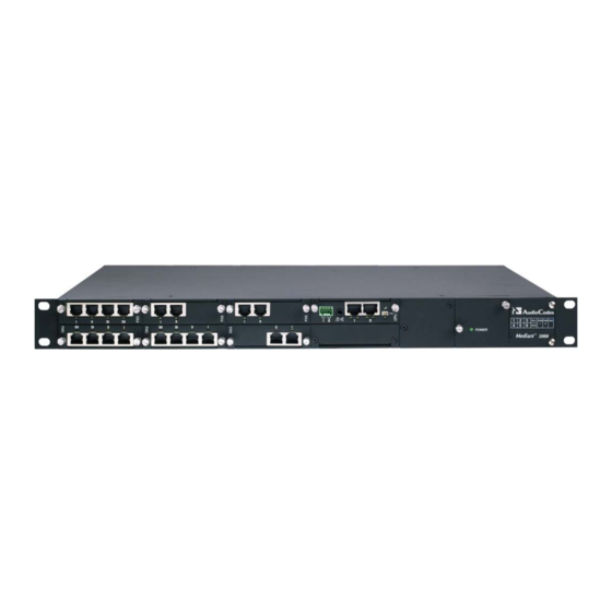
Installation Manual 2. Installing the Device Installing the Device This section describes the device's hardware installation, which includes the following: Physical description of the device (refer to 'Installing the Device' on page 11) List of shipped items (refer to 'Unpacking Package Contents' on page 14) Mounting the device (refer to 'Mounting the Device' on page 15) Cabling the device (refer to 'Cabling the Device' on page 17) Physical Description... -
Page 12: Table 2-1: Front Panel Component Descriptions
Mediant 1000 Table 2-1: Front Panel Component Descriptions Label/ Component Description Item # Module (Optional) FXO and FXO G module: The device can house up to six FXO modules. Each module provides four RJ-11 ports. Therefore, up to 24 FXO ports (i.e., 6 modules x 4 ports) are supported. - Page 13 Installation Manual 2. Installing the Device Label/ Component Description Item # Module CPU - Enlarged View (#3) Locking screws (2). Dry contact port (normally open) - can be connected to an external audible or visual alarm system (e.g., bell, siren, hooter, or light). Dry contact port (normally closed).
-
Page 14: Rear Panel
Four anti-slide bumpers for desktop installation option. • Two-meter length RS-232 DB-9 adaptor cable (for direct serial connection to PC). Check, retain and process any documents. Notify AudioCodes or your local supplier of any damage or discrepancies. Installation Manual Document #: LTRT-83506... -
Page 15: Mounting The Device
Installation Manual 2. Installing the Device Mounting the Device The device can be mounted in one of the following ways: Placed on a desk top (refer to 'Desktop Mounting' on page 15) Installed in a standard 19-inch rack (refer to 'Installing the Device in a 19-inch Rack' on page 16) 2.3.1 Desktop Mounting... -
Page 16: Installing The Device In A 19-Inch Rack
Mediant 1000 Peel off the adhesive, anti-slide rubber feet and stick one in each anti-slide groove. Figure 2-5: Peeled-off Rubber Foot Flip the device over again so that it rests on its underside and place it in the required position on a desktop. - Page 17 Installation Manual 2. Installing the Device To mount the device on a pre-installed shelf in the rack: Place the device on a pre-installed shelf in the rack. It's recommended to attach the device's integral front mounting brackets to the rack's frame to prevent it from sliding off the shelf during cabling.
-
Page 18: Cabling The Device
Mediant 1000 Cabling the Device This section describes the cabling of the device, which includes the following: Connecting to earth/ground (refer to 'Earthing (Grounding) the Device' on page 18) Protective Earthing The equipment is classified as Class I EN60950 and UL60950 and must be earthed at all times. -
Page 19: Connecting To Earth (Ground)
Installation Manual 2. Installing the Device 2.4.1 Connecting to Earth (Ground) The device must be permanently connected to earth (ground), using an equipment-earthing conductor. Protective Earthing The equipment is classified as Class I EN60950 and UL60950 and must be earthed at all times. To earth the device: Connect an electrically earthed strap of 16 AWG wire (minimum) to the chassis' earthing screw (located on the rear panel), using the supplied washer. -
Page 20: Connecting To The Ip Network
Mediant 1000 2.4.2 Connecting to the IP Network The device's CPU module provides two 10/100Base-TX RJ-45 ports for connectivity to the Ethernet network (IP network). The dual ports provide Ethernet redundancy. To connect the device to the IP/Ethernet network: On the CPU module, connect the first Ethernet port (labeled I) directly to the Ethernet network, using a straight-through RJ-45 Ethernet cable. -
Page 21: Connecting To Fxs/Fxo Interfaces
Installation Manual 2. Installing the Device 2.4.3 Connecting to FXS/FXO Interfaces The procedure below describes the cabling of the device's FXS and FXO module analog interfaces. Warnings: • To protect against electrical shock and fire, use a 26 AWG min wire to connect FXO ports to the PSTN. -
Page 22: Figure 2-9: Rj-11 Connector Pinouts For Fxs Lifeline
The Lifeline splitter connects pins 1 and 4 to another source of an FXS port, and pins 2 and 3 to the POTS phone, as shown in the figure below. Figure 2-9: RJ-11 Connector Pinouts for FXS Lifeline Figure 2-10: Mediant 1000 Analog Lifeline Cable Setup Table 2-3: FXS Lifeline Setup Component Descriptions Item # Component Description Lifeline phone. -
Page 23: Connecting To Isdn Bri Lines
Installation Manual 2. Installing the Device 2.4.5 Connecting to ISDN BRI Lines The device can house up to five BRI modules, each supporting four BRI ports, thereby providing a total of up to 20 BRI ports. Warning: To protect against electrical shock and fire, use a 26 AWG min wire to connect the BRI ports to the PSTN. -
Page 24: Connecting To E1/T1 Trunks
Mediant 1000 2.4.6 Connecting to E1/T1 Trunks The procedure below describes the cabling of the device's TRUNKS module interfaces (i.e., E1/T1 trunks). Warning: To protect against electrical shock and fire, use a 26 AWG min wire to connect T1 or E1 ports to the PSTN. -
Page 25: Connecting To E1/T1 Trunks For Pstn Fallback
Trunk from the PBX is routed from the module to the PSTN. Figure 2-13: Mediant 1000 Digital Lifeline Cabling (e.g., Trunks 1 and 2) To connect the digital trunk interfaces for 1+1 or 2+2 PSTN Fallback: On the same TRUNKS module, connect Trunk 1 and Trunk 3 to your PBX, and Trunk 2 and Trunk 4 to the PSTN. -
Page 26: Connecting To Dry Contact Relay Alarm System
Mediant 1000 2.4.8 Connecting to Dry Contact Relay Alarm System The dry contact ports I and II located on the device's CPU module, allows you to connect the device to an external audible or visual alarm system. The table below describes the operational status of these dry contact ports. -
Page 27: Connecting Rs-232 Serial Interface To Pc
Installation Manual 2. Installing the Device To set up a dry contact system: Insert two wires into the mate’s spring-cage wire connectors in position 4 and 3 for the device's dry contact Port I, and two wires in position 2 and 1 (for the device's dry contact Port II), by performing the following: With a sharp, pointed object, press the position's corresponding orange button;... -
Page 28: 2.4.10 Connecting To Power
Mediant 1000 2.4.10 Connecting to Power The device can house up to two extractable power supply modules (Power 1 and Power 2), each providing an AC power connector on the device's rear panel. The dual power option provides the device with power redundancy. -
Page 29: Maintenance
(I/O) interface modules (i.e., TRUNKS, BRI, FXS, FXO, and MPM). Figure 2-17: Mediant 1000 Front Layout The guidelines for slot assignment for these modules, include the following: The TRUNKS, BRI, FXS, and FXO modules must be housed in consecutive slots. In other words, if the device houses three modules, then they must occupy slots 1, 2, and 3 (no skipping of slots). -
Page 30: Replacing Modules
Mediant 1000 For example, if the device requires one TRUNKS module and two FXS modules, then you must insert the TRUNKS module in Slot 1 and the two FXS modules in slots 2 and 3 respectively. If at a later stage, you wish to add a BRI module (for example), then you must replace the FXS module in Slot 2 with the new BRI module, and then re- insert this replaced FXS module in Slot 4. -
Page 31: Figure 2-19: Module Orientation In Chassis Top- And Bottom-Row Slots
Installation Manual 2. Installing the Device To replace I/O modules: Software-remove the module, using the device's Web interface's 'Home' page (refer to the device's User's Manual). Disconnect the cables from the module that you want to replace. Physically remove the module from the device's front-panel slot, by performing the following: Using a flathead screwdriver, loosen the module's two mounting screws. -
Page 32: Inserting Modules Into Previously Empty Slots
Mediant 1000 2.5.3 Inserting Modules into Previously Empty Slots The procedure below describes how to add additional I/O modules to previously empty slots in the device's chassis. Warning: Ensure that you power down the device before adding a module to a previously empty slot. -
Page 33: Replacing The Air Filter
Installation Manual 2. Installing the Device 2.5.4 Replacing the Air Filter The Fan Tray module includes six integrated fans, which cool the device's internal components. The Fan Tray module draws in air through a perforated grill on the right side of the chassis. -
Page 34: Figure 2-21: Fan Tray With Filter Removed
Mediant 1000 With your fingertips, grasp the steel frame of the air filter and separate it from the Fan Tray module; you should be able to remove it relatively easily. The figure below shows the air filter extracted from the Fan Tray module. -
Page 35: Configuring The Device
Installation Manual 3. Configuring the Device Configuring the Device This section describes initial, basic setup configuration for the device, using the device's embedded Web server (Web interface). Notes: • The device is supplied with application software (cmp file) already residing on its flash memory. This software is set to factory defaults. •... -
Page 36: Assigning An Ip Address Using Http
Mediant 1000 3.1.1 Assigning an IP Address using HTTP You can assign an IP address to the device, using the device's Web interface. To assign an IP address using HTTP: Disconnect the device from the network and reconnect it to a PC using one of the following methods: •... -
Page 37: Assigning An Ip Address Using Bootp
PC and re-access the device via the Web interface with its newly assigned IP address. 3.1.2 Assigning an IP Address using BootP You can assign an IP address to the device, using the supplied AudioCodes' BootP/TFTP Server application. Notes: •... -
Page 38: Assigning An Ip Address Using The Voice Menu Guidance
Mediant 1000 Click Apply to save the new client. Click OK; the ‘Client Configuration’ screen closes. Physically reset the device using the hardware reset button (or power down and then power up the device). This causes the device to use BootP; the device changes its network parameters to the values provided by BootP. - Page 39 Installation Manual 3. Configuring the Device To change the IP address: Press 1 followed by the pound key (#); The current IP address of the device is played. Press the # key. Dial the new IP address. Use the star (*) key instead of periods (.), e.g., 192*168*0*4, and then press # to finish.
-
Page 40: Table 3-2: Configuration Parameters Available Via The Voice Menu
Mediant 1000 Dial 32 followed by the # key, and then perform the following to change the configuration file name pattern: Press the # key. Select one of the patterns listed in the table below (aa.bb.cc.dd denotes the IP address of the configuration server):... -
Page 41: Assigning An Ip Address Using The Cli
Installation Manual 3. Configuring the Device Item Number at Description Menu Prompt Primary DNS server IP address. DHCP enable / disable. Configuration server IP address. Configuration file name pattern. Voice menu password (initially 12345). Note: The voice menu password can also be changed using the Web interface or ini file parameter VoiceMenuPassword (refer to the User's Manual). -
Page 42: Configuring Basic Sip Parameters
Mediant 1000 Configuring Basic SIP Parameters Once you have completed the previous sections, you are ready to start configuring the device using the Web interface. For information on how to fully configure the device, refer to the device's User’s Manuals. -
Page 43: Enabling Channels And Configuring Call Routing (Example)
Installation Manual 3. Configuring the Device 3.2.1 Enabling Channels and Configuring Call Routing (Example) This section provides an example for enabling the device's channels and for configuring Tel (PSTN)-to-IP call routing. This includes assigning the channels a telephone number and then routing calls (e.g., of dialed numbers with prefix 10) from these channels to a specific IP destination (e.g., IP address 10.33.24.14). -
Page 44: Figure 3-4: Routing Tel Calls To An Ip Address
Mediant 1000 Configure routing rules for telephone calls (i.e., Tel or inbound IP) to an IP destination (i.e., IP address): Open the ‘Outbound IP Routing’ page (Configuration tab > Protocol Configuration menu > Routing Tables submenu > Tel to IP Routing). -
Page 45: Configuring Pstn Trunks
Installation Manual 3. Configuring the Device Configuring PSTN Trunks This section describes how to configure the configure the device's E1/T1 PRI and BRI trunks. To configure the trunks: Open the ‘Trunk Settings’ page (Configuration tab > PSTN Settings menu > Trunk Settings). - Page 46 Mediant 1000 From the ‘Framing Method’ drop-down list, select the required framing method. For E1 trunks, always set this parameter to ‘Extended Super Frame’. From the ‘Clock Master’ drop-down list, select the trunk's clock source: • ‘Recovered’ = clock source is recovered from the trunk.
-
Page 47: Saving And Resetting The Device
Installation Manual 3. Configuring the Device Saving and Resetting the Device To apply configuration changes to the device's volatile memory (RAM), click the Submit button located on the page in which you are configuring. Modifications to parameters with on-the-fly capabilities are immediately applied to the device; other parameters are applied only after a device reset. -
Page 48: Changing Login User Name And Password
For detailed information on the Web user accounts, refer to the device's User’s Manual. Tip: If you do not know your user name and password, you can use AudioCodes BootP/TFTP utility to access the device, by re-flash the load and resetting the password (refer to the Product Reference Manual). -
Page 49: Backing Up And Restoring Configuration
Installation Manual 3. Configuring the Device Backing Up and Restoring Configuration You can save a copy/backup of the device's current configuration settings (Voice) as an ini file to a folder on your PC, using the 'Configuration File' page. The saved ini file includes only parameters that were modified and parameters with other than default values. -
Page 50: Restoring Factory Default Settings
Mediant 1000 To load (or restore) the ini file: Click the Browse button, navigate to the folder in which the ini file is located, select the file, and then click Open; the name and path of the file appear in the field beside the Browse button. -
Page 51: Upgrading The Device
Installation Manual 3. Configuring the Device Upgrading the Device You can upgrade the device with the following files, using the device's Web interface: Firmware (cmp) file using the Web interface's Software Update Wizard (refer to 'Software Upgrade Wizard' on page 51). Auxiliary and ini files using the 'Load Auxiliary Files' page (refer to 'Upgrading the ini and Auxiliary Files' on page 54). -
Page 52: Figure 3-9: Start Software Upgrade Wizard Screen
Mediant 1000 Notes: • Before you can load an ini or any auxiliary file, you must first load a cmp file. • When you activate the wizard, the rest of the Web interface is unavailable. After the files are successfully loaded, access to the full Web interface is restored. -
Page 53: Figure 3-10: Load Cmp File Wizard Page
Installation Manual 3. Configuring the Device Figure 3-10: Load CMP File Wizard Page Note: At this stage, you can quit the Software Update Wizard, by clicking Cancel , without requiring a device reset. However, once you start uploading a cmp file, the process must be completed with a device reset. Click the Browse button, navigate to the cmp file, and then click Send File;... -
Page 54: Figure 3-11: End Process Wizard Page
Mediant 1000 You can now choose to either: • Click Reset; the device resets, utilizing the new cmp and ini file you loaded up to now as well as utilizing the other auxiliary files. • Click Back; the 'Load a cmp file' page is opened again. -
Page 55: Loading Ini And Auxiliary Files
Installation Manual 3. Configuring the Device 3.8.2 Loading ini and Auxiliary Files The auxiliary files (and ini file) are dat files that can be loaded to the device to provide enhanced device provisioning. These files are described in the table below. For detailed information on these files, refer to the device's User's Manual. -
Page 56: Figure 3-12: Load Auxiliary Files Page
Mediant 1000 To load an auxiliary file to the device: Open the 'Load Auxiliary Files' page (Management tab > Software Update menu > Load Auxiliary Files). Figure 3-12: Load Auxiliary Files Page Click the Browse button corresponding to the file type that you want to load, navigate to the folder in which the file is located, and then click Open;... -
Page 57: Monitoring The Device
Installation Manual 4. Monitoring the Device Monitoring the Device The operating status of the device can be monitored in the following ways: Monitoring the device's hardware front-panel LEDs (refer to 'Front-Panel LEDs' on page 57). Monitoring the device using the Web interface (refer to 'Web Interface' on page 58). Front-Panel LEDs The location of the device's front panel LEDs are shown in the figure below and described in the subsequent table. -
Page 58: Table 4-3: Bri I/O Modules Led Description
Mediant 1000 Table 4-3: BRI I/O Modules LED Description Color State Description RJ-45 Green Physical layer (Layer 1) is synchronized (normal operation). Physical layer (Layer 1) is not synchronized. Trunk is not active. Table 4-4: Power Supply Module LED Description... -
Page 59: Web Interface
Installation Manual 4. Monitoring the Device Web Interface The Web interface's 'Home' page provides a graphical display of the device's front panel, displaying color-coded icons depicting the status of the device's ports and channels, as well as other interfaces of the device. In addition, the 'Home' page allows you quick access to viewing active alarms. -
Page 60: Viewing Channel Status
You can use these port icons to drill down to view detailed channel status. For a detailed description of the 'Home' page, refer to the device's User's Manual. Figure 4-3: Mediant 1000 Web Interface’s Home Page Table 4-6: Color-Coding of Trunk / Channel Status Icon... -
Page 61: Open Solution Network (Osn) Server Platform
Installation Manual 5. Open Solution Network (OSN) Server Platform Open Solution Network (OSN) Server Platform This section is intended for customers who wish to install the optional Open Solution Network (OSN) server platform functionality. The device's chassis houses a plug-in OSN Server module for hosting third-party, VoIP applications such as IP-PBX, Pre-Paid, and IP- PBX redundancy. -
Page 62: Figure 5-2: Ipmx Module (Only For Osn1)
Mediant 1000 Note: The CM module is applicable only to OSN1. iPMX module (housed in the rear panel): Figure 5-2: iPMX Module (Only for OSN1) Figure 5-3: iPMX Module (For OSN2) Hard Drive module (HDMX) (housed in the rear panel):... -
Page 63: Required Working Tools
Installation Manual 5. Open Solution Network (OSN) Server Platform 5.1.1 Required Working Tools The following tools are required for installing the OSN Server module: Phillips screwdriver Flathead screwdriver Wire cutter 5.1.2 Installing the CM Module The Connection Module (CM) is housed in the device's front panel. Note: The CM module is applicable only to OSN1. -
Page 64: Installing The Ipmx Module
Mediant 1000 5.1.3 Installing the iPMX Module The iPMX module is installed on the rear panel of the device, as described in the following procedure: To install the iPMX module: On the device's rear panel, remove the black metal cover plates in the first and second slots located on the right side of the power connection, as shown in the figure below. -
Page 65: Installing The Hdmx Module
Installation Manual 5. Open Solution Network (OSN) Server Platform Insert the iPMX module into the first slot, closest to the power connection, as shown in the figure below. Figure 5-8: Inserting iPMX Module Push the iPMX module into the slot and press on it firmly to ensure it has been fully inserted. -
Page 66: Replacing The Ipmx Module's Lithium Battery
5.1.5 Replacing the iPMX Module's Lithium Battery The iPMX module is equipped with a 3-volt CR-1225 Lithium battery (AudioCodes product number: ACL P/N RBAT00001). Typically, battery life is estimated at two years. However, for various reasons, the battery may last for a shorter duration. -
Page 67: Figure 5-10: Removing Lithium Battery From Ipmx Module
Installation Manual 5. Open Solution Network (OSN) Server Platform The following procedure describes how to replace the Lithium battery in the iPMX module. To replace the Lithium battery in the iPMX: Remove the iPMX module from the slot in which it's housed in the device rear panel, by performing the following: Using a flathead screwdriver, loosen the module's two lower mounting captive screws. -
Page 68: Installing Linux™ On The Osn Server
Mediant 1000 Installing Linux™ on the OSN Server This section describes the installation of the Linux operating system on the OSN server. The OSN server supports the following Linux OS distributions: Linux RedHat (and Fedora) Linux Debian Linux SUSE Linux CentOS 5.2.1... -
Page 69: Cabling
Installation Manual 5. Open Solution Network (OSN) Server Platform 5.2.2 Cabling The following procedure describes the cabling procedure before installing Linux on the device's OSN Server. 5.2.2.1 Cabling OSN1 The procedure below describes the OSN1 cabling for Linux installation. The cabling is performed on the CM module. -
Page 70: Cabling Osn2
Mediant 1000 5.2.2.2 Cabling OSN2 The procedure below describes the OSN2 cabling for Linux installation. The cabling is performed on the iPMX module. Note: If you want to use the VGA port, you can order the VGA cable separately from AudioCodes. -
Page 71: Installing Linux
Installation Manual 5. Open Solution Network (OSN) Server Platform 5.2.3 Installing Linux Once you have cable the device as described in the previous section, you can install the Linux OS. To install Linux on the OSN server: Start a terminal application (e.g. HyperTerminal) on your PC, and create a new connection with the following settings: •... -
Page 72: Figure 5-14: Enabling System Management Bios
Mediant 1000 Change the System Management BIOS parameter to “Enabled”. Figure 5-14: Enabling System Management BIOS Press the Esc key to return to the main BIOS window: Figure 5-15: Saving BIOS Settings Choose the Write to CMOS and Exit option, and then press the Y key to save changes and exit. -
Page 73: Connecting Remotely To Osn Server Using Windows
Installation Manual 5. Open Solution Network (OSN) Server Platform Press the Enter key; the Linux installation begins. Continue installation according to the Linux installation instructions. Connecting Remotely to OSN Server using Windows Typically, for customers requiring Microsoft Windows® operating system (OS), the OSN Server is provided with Windows pre-installed. -
Page 74: Connecting Using Remote Desktop Connection
Mediant 1000 5.3.2 Connecting Using Remote Desktop Connection Once you have cabled the PC to the OSN Server, perform the procedure below for connecting the PC remotely to the OSN Server (running Windows) using the Remote Desktop Connection program. To remotely connect a PC to the OSN Server running Windows: Change the PC's IP address so that it is in the same subnet as the default OSN Server's IP address (i.e., 10.1.10.12). -
Page 75: Figure 5-18: Entering Ip Address In Remote Desktop Connection
Installation Manual 5. Open Solution Network (OSN) Server Platform Start Microsoft's Remote Desktop Connection program - from the Start menu, point to Programs, to Accessories, to Communications, and then click Remote Desktop Connection. Figure 5-18: Entering IP Address in Remote Desktop Connection In the 'Computer' field, enter the OSN Server's default IP address (i.e., 10.1.10.12). -
Page 76: Version 6.0
Installation Manual Version 6.0 www.audiocodes.com...
Need help?
Do you have a question about the Mediant 1000 and is the answer not in the manual?
Questions and answers