
Subscribe to Our Youtube Channel
Related Manuals for Gira KNX 2139 00


Summary of Contents for Gira KNX 2139 00
- Page 1 Product documentation Issue: 21.06.2022 21393100 Heating actuator 6-gang with controller Order no. 2139 00...
-
Page 2: Table Of Contents
Table of Contents Table of Contents Information on the product .................... 6 Product catalogue .................... 6 Function ......................... 6 Device components ..................... 10 Technical data...................... 11 Safety instructions ...................... 12 Mounting and electrical connection ................. 13 Commissioning........................ 15 Application programs ...................... 17 Scope of functions...................... 18 Notes on software ...................... 21 Operation and indication .................... 22 Button operation and indication functions ............ - Page 3 Table of Contents 9.4.6 "Valve output - General" parameters ............ 75 9.4.7 Objects for "Valve output - General"............ 80 Cyclical command value monitoring / emergency operation........ 81 9.5.1 Command value monitoring / emergency operation parameters..... 84 9.5.2 Objects for command value monitoring / emergency operation .... 85 Command value limit ...................
- Page 4 Table of Contents 10.4.2 Command value limit parameters ............ 169 10.4.3 Objects for command value output and command value limit .... 170 10.4.4 Objects for command value limit ............ 181 10.5 Room temperature measurement .............. 181 10.5.1 Temperature measurement parameters .......... 185 10.5.2 Objects for temperature measurement ..........
- Page 5 Table of Contents 11.6 Limit value switch.................... 245 11.6.1 Limit value switch parameters ............... 247 11.6.2 Limit value switch object list .............. 253 12 As-delivered state ...................... 256 Heating actuator 6-gang with controller | Order no. 2139 00 | 21393100 Page 5 of 257...
-
Page 6: Information On The Product
Information on the product | Product catalogue Information on the product Product catalogue Product name: Heating actuator 6-gang with controller Use: Actuator Design: RMD (rail-mounted device) Order no. 2139 00 Function General The heating actuator is used for the activation of electrothermal actuators (ETA) for heating or cooling systems. - Page 7 Information on the product | Function The heating actuator possesses a heat requirement and pump controller. This pro- duces a positive impact on the energy consumption of a housing or commercial build- ing through the transmission and evaluation of the largest command value in the heating or cooling system.
- Page 8 Update capability The device can be updated. Firmware can be easily updated with the Gira ETS Ser- vice App (additional software). Heating actuator 6-gang with controller | Order no. 2139 00 | 21393100...
- Page 9 The device is designed for mounting on DIN rails in closed compact boxes or in dis- tributors in fixed installations in dry interior rooms. We recommend using electrothermal actuators of make Gira or, alternatively, models of make Möhlenhoff (AA2004, AA4004) or Sauter (MTX). Always ob- serve the technical data of the actuators and compare them with the technical properties of the heating actuator.
-
Page 10: Device Components
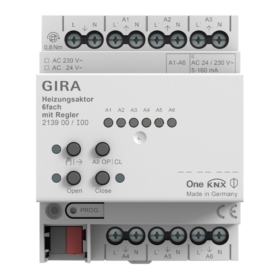
Information on the product | Device components Device components Image 1: Front view Supply of electrothermal valve drives Connection of electrothermal valve drives (A1 to A6) Status LEDs for outputs Button field for manual operation Programming button and LED Bus connection If all of the status LEDs (3) are flashing (2 Hz), the device is indicating that there is no power supply to the electrothermal valve drives (1). -
Page 11: Technical Data
Information on the product | Technical data Technical data KNX medium TP256 Commissioning mode S-mode Rated voltage KNX DC 21 ... 32 V SELV Current consumption KNX 4.5 ... 10 mA Ambient conditions Ambient temperature -5 ... +45 °C Storage/transport temperature -25 ... -
Page 12: Safety Instructions
Safety instructions Safety instructions Electrical devices may only be mounted and connected by electrically skilled persons. Failure to observe the instructions may cause damage to the device and result in fire and other hazards. Danger of electric shock. Device is not suitable for disconnection from supply voltage. -
Page 13: Mounting And Electrical Connection
Mounting and electrical connection Mounting and electrical connection DANGER! Electric shock when live parts are touched. Electric shocks can be fatal. Before carrying out work on the device or load, disengage all the corresponding cir- cuit breakers. Cover up live parts in the working environment. Mounting the device –... - Page 14 Mounting and electrical connection Image 2: Connection of 230 V valve drives ■ Connect AC 24 V valve drives according to the connection diagram (see figure 3). Image 3: Connection of 24 V valve drives ■ Connect the supply for the valve drives to the terminals 8(L) and 8(N) (1). ■...
-
Page 15: Commissioning
Commissioning Commissioning The device is commissioned with the ETS version 5.7.7 or higher. Safe-state mode The safe-state mode stops the execution of the loaded application program. Only the system software of the device is still functional. ETS diagnosis func- tions and programming of the device are possible. Manual operation is not possible. - Page 16 Commissioning Restoring the device to factory settings Devices can be reset to factory settings with the Gira ETS Service App. This function uses the firmware contained in the device that was active at the time of delivery (as- delivered state). Restoring the factory settings causes the devices to lose their phys- ical address and configuration.
-
Page 17: Application Programs
Application programs Application programs ETS search paths: heating, air condition / valves / Heating actuator, 6-gang with controller Application: Name Heating actuator 6-gang 20E021 Version 2.1 for ETS5 version 5.7.7 or higher and ETS6 version 6.0.3 or higher from mask version SystemB (07B0) Summarized de- Multifunctional heating actuator application:... -
Page 18: Scope Of Functions
Scope of functions Scope of functions Valve outputs – 6 independent electronic valve outputs. – Valve activation (deenergised opened / closed) can be configured for each output. – Command value evaluation as "Switching, 1-bit", "Constant, 1-byte" or "Con- stant, 1-byte with command value limiting value and hysteresis". –... - Page 19 Scope of functions – Manual operation of outputs independent of the KNX (for instance, construc- tion site mode) with LED status indicators. Separate status feedback to the KNX for manual operation. Manual operation can also be disabled via the KNX. Own cycle time and PWM setting for manually-operated valve outputs. Central activation of all valve outputs (0% / 100%).
- Page 20 Scope of functions – Room temperature measurement via up to two external KNX temperature sensors. Calibration of the temperature values possible and measured value formation of the external sensors can be configured. Settable polling time of the externally received temperature values. –...
-
Page 21: Notes On Software
Notes on software Notes on software Unloading the application program The application program can be unloaded with the ETS. In this case, all valve outputs of the product are switched off. Manual operation is possible. ETS project design and commissioning For project design and commissioning of the device, ETS5 version 5.7.7 or higher or ETS6 version 6.0.3 or higher is required. -
Page 22: Operation And Indication
Operation and indication | Button operation and indication functions Operation and indication Button operation and indication functions Image 4: Operating elements A1...A6: status LED outputs (LEDs light up when outputs are energised) ǃ button: activation / deactivation of manual operation LED - On: permanent manual operation mode active Open button: open valve (configured valve direction of action is taken into account) LED –... - Page 23 Operation and indication | Button operation and indication functions Valve drive LED ON LED OFF Deenergised opened Output energised Output not energised Valve closed / Closing Valve opened / Opening phase phase Active heating or cooling – LED flashes slowly: output in manual operation mode –...
- Page 24 Operation and indication | Button operation and indication functions Switching on temporary manual operation mode Manual operation is enabled in the ETS and not blocked. ■ Press the ǃ button briefly. Temporary manual operation mode is active. The status LED A1 flashes. The LED ǃ flashes. After temporary manual operation mode has been switched on, the most re- cently set states of the outputs initially remain active.
- Page 25 Operation and indication | Button operation and indication functions Permanent manual operation mode is active and the LED ǃ is illuminated. The status LED A1 flashes. The two status LEDs OPEN and CLOSE show the current status of A1. After permanent manual operation mode has been switched on, the states of the outputs last set initially remain active.
- Page 26 Operation and indication | Button operation and indication functions The valve closes (configured valve direction of action is taken into account). The LEDs OPEN and CLOSE display the valve status. Temporary manual operation mode: After running through all of the outputs, the device exits manual operation mode after the ǃ...
- Page 27 Operation and indication | Button operation and indication functions The status LED of the selected output A1...A6 flashes. The two status LEDs OPEN and CLOSE show the current status of the selected output. ■ Press the OPEN and CLOSE buttons simultaneously for at least 5 seconds. The selected valve output is disabled (activation via the bus no longer pos- sible).
-
Page 28: Ets Configuration
Operation and indication | ETS configuration ETS configuration 8.2.1 Manual operation All outputs of the device have electronic manual operation. The button field with 4 function buttons and 3 status LEDs on the front panel of the device can be used for setting the following modes of operation: –... - Page 29 Operation and indication | ETS configuration After return of bus voltage, a disabled state that was active beforehand is al- ways inactive when the polarity of the disabling object is non-inverted. When an active manual operation is terminated by a disable, the actuator will also transmit a "Manual operation inactive"...
- Page 30 Operation and indication | ETS configuration During active permanent manual operation, all incoming telegrams are tracked internally. At the end of manual operation, the outputs will be set to the tracked states or to the positions last set before the permanent manual operation. The individual priorities of the functions with respect to one another are taken into account here.
-
Page 31: Status Indication
Operation and indication | ETS configuration ■ Activate the parameter "Disable bus control of individual outputs" on the para- meter page "Manual operation". The function for disabling the bus control is enabled and can be activated loc- ally. Alternatively, deactivating the parameter prevents disabling of the bus control from being activated in permanent manual operation mode. - Page 32 Operation and indication | ETS configuration status display. If a temporary status indication has been activated by pressing the "Manual operation" button, the object transmits the value "ON". If the object receives a telegram with the value "OFF" or "ON", the status LEDs indicate the status of the outputs according to the display length.
-
Page 33: Operation And Indication Parameters
Operation and indication | Operation and indication parameters Operation and indication parameters Manual operation Manual operation Checkbox (yes / no) Manual operation is possible while the device is supplied with power from the bus supply voltage. This parameter defines whether manual operation is to be possible or deactivated permanently. - Page 34 Operation and indication | Operation and indication parameters Function 0 = inactive; 1 = manual operation active 0 = inactive; 1 = permanent manual oper- ation active This parameter defines the information contained in the status object. The object is always "OFF"...
- Page 35 Operation and indication | Operation and indication parameters Indicating status temporarily Checkbox (yes / no) The status LEDs on the front of the device can indicate the current status of the out- puts permanently or temporarily. Parameter deactivated: Continuous status indication. In this case, the status LEDs always indicate the current status of the outputs.
-
Page 36: Operation And Indication Object List
Operation and indication | Operation and indication object list Operation and indication object list Object no. Function Name Type Flag Disabling Manual operation - 1-bit 1,003 C, (R), W, -, Input 1-bit object for disabling manual operation on the device. The polarity can be con- figured. -
Page 37: Valve Outputs
Valve outputs | Priorities for valve outputs Valve outputs Priorities for valve outputs The heating actuator distinguishes between various functions and events, which either affect all of some of the assigned valve drives globally, or only specifically af- fect individual outputs. Because these functions and events cannot be executed sim- ultaneously, there must be priority control. -
Page 38: Channel Configuration
Valve outputs | Channel configuration configured in such a way that the starting state should be tracked at the end of this function. Permanent manual operation is now activated. The actuator assumes the command value of manual operation (e.g. 50%). Whilst manual operation is active, service mode is deactivated via the KNX. -
Page 39: Channel Configuration Parameters
Valve outputs | Channel-independent functions blocks or in hotel rooms). In the parameter setting "individually", each valve output possesses its own para- meter pages in the ETS. 9.2.1 Channel configuration parameters General -> Configuration VO x (x = 1 ... 6) Use Checkbox (yes / no) Valve outputs that are not required can be activated or deactivated. - Page 40 Valve outputs | Channel-independent functions In addition, valve outputs, which receive preset command values via the data format "Switching (1-bit)" and "Switching (1-byte) with command value limiting value", influence the heat requirement control. In the case of "Switching (1- bit)", an "OFF" command value is interpreted as "0%" and an "ON" command value as "100%".
- Page 41 Valve outputs | Channel-independent functions Optionally, the actuator can evaluate an external telegram for heat requirement in- formation (e.g. from another heating actuator). This allows the cascading of multiple actuators with a heat requirement signal. The local heating actuator links the 1-bit telegram value of "External heat requirement"...
- Page 42 Valve outputs | Channel-independent functions ■ Deactivate the checkbox "Detect external heat requirement via object". Detection of an external heat requirement is not possible. The actuator only determines the heat requirement information itself. Cyclical telegrams to the object "Heat requirement - External" with an identical telegram polarity (ON ->...
- Page 43 Valve outputs | Channel-independent functions Switch-on delay (heat requirement) 0...23 h 0...5...59 min 0…59 s The actuator only outputs the telegram of an active heat requirement after determin- ation when the delay time defined here has elapsed. No heat requirement request is transmitted if the actuator no longer determines a heat requirement within the time preset here.
-
Page 44: Pump Control
Valve outputs | Channel-independent functions 9.3.1.2 Objects for heat requirement Object no. Function Name Type Flag Heat requirement - General valve out- 1-bit 1,002 C, R, -, T, - Status puts - Output 1-bit output object for the transmission of general heat requirement information to suitable burner and boiler controllers. - Page 45 Valve outputs | Channel-independent functions command value is interpreted as "0%" and an "ON" command value as "100%". In the case of "Switching (1-byte) with command value limiting value", the actuator evaluates the converted switching output signal in the same way ("OFF"...
- Page 46 Valve outputs | Channel-independent functions The actuator only outputs the ON telegram to the pump after determination when the defined delay time has elapsed. The pump is not switched on when the actuator de- termines within the preset time that the pump must remain switched off, due to a lim- iting value plus hysteresis again being undershot.
- Page 47 Valve outputs | Channel-independent functions Enabling detection of an external pump control Optionally, the actuator can evaluate an external telegram for pump control (e.g. from another heating actuator). This allows the cascading of multiple actuators with pump control. The object must be enabled for an external pump control signal to be detected. ■...
- Page 48 Valve outputs | Channel-independent functions 9.3.2.1 Pump control parameters Enabling the pump control function General valve outputs -> Enabled functions Pump control Checkbox (yes / no) The heating actuator allows switching activation of the circulation pump of a heating or cooling circuit via a 1-bit KNX telegram. Here, the pump control of the actuator can be enabled centrally ("yes"...
- Page 49 Valve outputs | Channel-independent functions Switch-on time 1...5...15 minutes When anti-sticking protection is enabled, the length of pump running for the cyclical protection function must be preset here. The actuator then switches the pump on for the time set here without interruption, assuming that anti-sticking protection must be executed.
-
Page 50: Largest Command Value
Valve outputs | Channel-independent functions Object no. Function Name Type Flag Pump control - General valve out- 1-bit 1,001 C, R, -, T, - Switch puts - Output 1-bit output object for direct activation of a circulation pump of the heating or cooling system. - Page 51 Valve outputs | Channel-independent functions In the case of valve outputs configured in the ETS to the command value data formats "Switching (1-bit)" or "Constant (1-byte) with command value limiting value", there is no evaluation of the command values preset via the bus. Exception: It may also occur with such command value outputs that a constant command value is active (after bus voltage return, after an ETS programming operation, during manual operation, with an active forced position and with...
- Page 52 Valve outputs | Channel-independent functions Enabling recording of an external largest command value Optionally, the actuator can evaluate an external telegram for the largest command value (e.g. from another heating actuator). This allows the cascading of multiple actu- ators with a command value signal. The object must be enabled for an external largest command value to be recorded.
- Page 53 Valve outputs | Channel-independent functions Setting the "Largest command value" function General valve outputs -> Largest command value on change Transmit cyclical on change and cyclical The largest command value determined by the heating actuator is actively transmit- ted to the bus. This parameter decides when a telegram is transmitted via the "Largest command value"...
-
Page 54: Summer / Winter Mode Switchover
Valve outputs | Channel-independent functions Object no. Function Name Type Flag Largest command General valve out- 1 bytes 5,001 C, R, -, T, - value - Status puts - Output 1-byte output object for transmission of the largest constant command value of the heating actuator to another bus device (e.g. - Page 55 Valve outputs | Channel-independent functions The "Summer" or "Winter" state preset via the object is stored internally in the device and is restored after a device reset. In the ETS, it is possible to configure whether, after an ETS programming operation, the saved value is restored or, alternatively, if a defined operation (summer or winter) is activated.
- Page 56 Valve outputs | Channel-independent functions In this configuration, the actuator activates the most recently saved operating mode. The operating mode tracked after bus voltage return or preset after an ETS programming operation is not tracked in the communication object "Summer / winter switchover"...
-
Page 57: Service Mode
Valve outputs | Channel-independent functions 9.3.4.2 Objects for summer / winter switchover Function toggling of the Summer / Winter operating mode Object no. Function Name Type Flag Summer / winter General valve out- 1-bit 1,002 C, (R), W, -, mode puts - Input 1-bit input object to switch over between summer and winter mode. - Page 58 Valve outputs | Channel-independent functions – Constant (1-byte) with command value limiting value: Valve closed = OFF Valve opened = ON The command value preset by an active service mode is also included in the determination of heat requirements and the largest command value. In addi- tion, service mode has an influence on pump control.
- Page 59 Valve outputs | Channel-independent functions Assignments can only be made on the parameter pages "VOx - General -> As- signments" if service mode is enabled on the "General valve outputs" para- meter page. Defining the behaviour at the end of service mode When service mode is deactivated, the assigned valve outputs are enabled again.
- Page 60 Valve outputs | Channel-independent functions 9.3.5.1 Service mode parameters The following parameters are parameterised on the parameter page "General -> General - Valve outputs -> Enabled functions". Service mode Checkbox (yes / no) Service mode allows the bus-controlled locking of the valve output in case of main- tenance or installation.
-
Page 61: Failure Of The Valve Operating Voltage
Valve outputs | Channel-independent functions Object no. Function Name Type Flag Service mode status Service mode - out- 1-bit 1,002 C, R, -, T, - 1-bit output object for status signalling of whether the service mode is active or not. In this case, the telegram polarity is fixed: "0"... - Page 62 Valve outputs | Channel-independent functions telegram transmission should take place after a device reset or not. After a device reset, the failure signal of the valve operating voltage can be optionally time-delayed with the delay being set globally for all feedback together on the para- meter page "General - Valve outputs".
-
Page 63: Valve Output - General
Valve outputs | Valve output - General Transmit after bus voltage return no / yes The object for the transmission of a failure of the valve operating voltage can actively transmit the feedback information after a bus voltage return and an ETS program- ming operation. -
Page 64: Data Formats For Command Values
Valve outputs | Valve output - General 9.4.2 Data formats for command values The heating actuator receives 1-bit or 1-byte command value telegrams, transmitted, for example, by KNX room temperature controllers. Usually, the room temperature controller determines the room temperature and generates the command value tele- grams using a control algorithm. - Page 65 Valve outputs | Valve output - General Valve outputs, which receive preset command values via the data format "Switching (1-bit)", influence the heat requirement and pump control. Here, an "OFF" command value is interpreted as "0%" and an "ON" command value as "100%".
- Page 66 Valve outputs | Valve output - General Often, control circuits are subject to non-constant changes in the setpoint presetting (e.g. frost protection, night operation, etc.) or short-time interference (e.g. measured value deviations due to brief opening of windows or doors near the sensor). For the setting of the scanning ratio of the required command value to take place as quickly and correctly in these cases, even with a longer set cycle time, without any negative impact on the reaction time of the control section, the actuator uses a special method...
- Page 67 Valve outputs | Valve output - General – Case 3 Command value change, e.g. from 80% to 30% during the opening phase of the valve (opening phase too long) (see figure 10). Before the reception of the new command value (30%), the old setpoint (80%) was active.
- Page 68 Valve outputs | Valve output - General automatically. The new duty factor is set immediately after the reception of the new com- mand value. Image 12: Example of a command value change 30% -> 80% during the closing phase of the valve –...
- Page 69 Valve outputs | Valve output - General does not produce the desired heating reaction, on account of the sluggishness. With sluggish underfloor heating systems, small constant command values (only short switch-on phases of the PWM) frequently do not produce any significant level of heating.
-
Page 70: Pwm Cycle Time
Valve outputs | Valve output - General Image 14: Example of command value evaluation with limiting value 9.4.3 PWM cycle time The "PWM cycle time" parameter specifies the period length of the pulse-width-mod- ulated output signal of a valve output. It allows adaptation to the adjusting cycle times (the adjusting time it takes the drive to bring the valve from its completely closed to its completely opened position) of the valve drives used. - Page 71 Valve outputs | Valve output - General – Disadvantage: It should be noted, that, due to the full valve lift, the life expectancy of the actu- ators can diminish. For very long cycle times (> 15 minutes) with less sluggish- ness in the system, the heat emission into the room, for example, in the vicin- ity of the radiators, can possibly be non-uniform and be found disturbing.
-
Page 72: Valve Direction Of Action
Valve outputs | Valve output - General Image 16: Ideal course of the valve stroke for a Cycle time < Adjusting cycle time The continuous flow of water through the valve, and thus the continuous heating of the drives causes variations and changes to the dead times of the drives during the opening and closing phase. -
Page 73: Reset Behaviour
Valve outputs | Valve output - General By contrast, switching command values are inverted for deenergised opened valve drives. Example: Command value ON -> Output switched off, Command value OFF - > Output switched on. On the LED status display, the valve direction of action configured for each output in the ETS is not taken into account. - Page 74 Valve outputs | Valve output - General (as would be the case if there was a faulty command value found in the course of command value monitoring)! The actuator only polls the command value preset for emergency operation. ■ Set the parameter to "Command value as before voltage failure". After bus voltage return, that command value is set at the valve output which was active at the moment of the last bus voltage failure.
-
Page 75: Valve Output - General" Parameters
Valve outputs | Valve output - General ■ Set the parameter to "Activate command value according to emergency opera- tion". For the valve output, the actuator polls the emergency operation command value, as configured in the ETS. Here, the active operating mode (summer / winter) is taken into account, providing that a summer / winter change-over is configured. - Page 76 Valve outputs | Valve output - General Valve output Activation with Pulse Width Modulation (PWM) Command value limiting value Pulse width modulation (PWM): Command values are implemented by the actuator with an equivalent pulse-width-modulated switch signal at the valve output. Command value limiting value: The constant command value is converted into a switching output signal, depending on a configured limiting value.
- Page 77 Valve outputs | Valve output - General PWM cycle time 0.5 minutes 1 minute 1.5 minutes 15 minutes 20 minutes The "PWM cycle time" parameter specifies the switching frequency of the pulse- width-modulated output signal of the valve output. It allows adaptation to the adjust- ing cycle times (the adjusting time it takes the drive to bring the valve from its com- pletely closed to its completely opened position) of the valve drives used.
- Page 78 Valve outputs | Valve output - General Reset behaviour After bus voltage return Specify command value Activate command value acc. to forced position Activate command value acc. to emer- gency operation Command value as before voltage failure After bus or mains voltage return, the valve outputs perform the configured reaction at this point.
- Page 79 Valve outputs | Valve output - General After ETS programming operation Command value as after voltage return Specify command value Command value according to forced posi- tion Command value according to emergency operation After an ETS programming operation, the valve outputs perform the configured reac- tion at this point.
-
Page 80: Objects For "Valve Output - General
Valve outputs | Valve output - General Command value 10 % 90 % 95 % 100 % The command value to be set after an ETS programming operation is defined here. This parameter is only visible on "Behaviour after ETS programming operation" = "Preset command value". -
Page 81: Cyclical Command Value Monitoring / Emergency Operation
Valve outputs | Cyclical command value monitoring / emergency operation Object no. Function Name Type Flag 21, 36, 51, Command value VOx - Input (x = 1 bytes 5,001 C, (R), W, -, 66, 81, 96 1...6) 1-byte input object for the presetting of a constant command value, e.g. of a KNX room temperature controller (0...100% ->... - Page 82 Valve outputs | Cyclical command value monitoring / emergency operation The configured valve direction of action (deenergised closed / deenergised opened) is taken into account in the electrical activation of the outputs by emergency operation. With deenergised closed valves, the switch-on time is derived directly from the configured PWM and the cycle time.
- Page 83 Valve outputs | Cyclical command value monitoring / emergency operation After a device reset (bus voltage return, ETS programming operation), the command value objects first contain the value "0". The state or emergency operation (active or inactive) is saved internally in the device after a bus voltage failure and is restored automatically after a bus voltage return.
-
Page 84: Command Value Monitoring / Emergency Operation Parameters
Valve outputs | Cyclical command value monitoring / emergency operation As soon as a command value telegram is missing on a monitored valve out- put, and thus emergency operation is activated, then the actuator transmits a fault signal via the object "Command value - Fault - Status" according to the configured telegram polarity. -
Page 85: Objects For Command Value Monitoring / Emergency Operation
Valve outputs | Command value limit Object polarity 1 = fault / 0 = no fault / 0 = fault / 1 = no fault If a command value fault is identified, then the actuator can optionally transmit a fault telegram via the object "Command value - Fault - Status". - Page 86 Valve outputs | Command value limit Setting the activation of the command value limit The "Activation" parameter on the parameter page "VOx - General - Command value monitoring" defines the type of action of the limiting function. The command value limit must be enabled. ■...
-
Page 87: Command Value Limit Parameters
Valve outputs | Command value limit In this setting, the actuator activates the command value limit automatically after an ETS programming operation. To deactivate the limit a "0" telegram must be received via the "Command value limit" object. The limit can be switched on or off at any time using the object. -
Page 88: Objects For Command Value Limit
Valve outputs | forced position Maximum command value 55 ... 100% The maximum command value that is valid when the command value limit is activ- ated is defined here. 9.6.2 Objects for command value limit Function: Command value limit Object no. Function Name Type... - Page 89 Valve outputs | forced position The actuator possesses a summer / winter switchover. Depending on the season, this allows the setting of different command value setpoints for a valve output for forced position Summer/winter switch-over for valve outputs. It is also possible to switch over the operating mode during an active forced position.
-
Page 90: Forced Position" Parameters
Valve outputs | forced position Updates of the object from "Forced position active" to "Forced position active" or from "Forced position inactive" to "Forced position inactive" produce no re- action. The status preset via the forced position object is stored internally in the device after a bus voltage failure and is restored automatically after a bus voltage return. - Page 91 Valve outputs | forced position Command value (summer) 10 % 30 % 90 % 100 % When forced operation is activated via a 1-bit object, after voltage return or after an ETS programming operation, it is possible to set the forced command value con- figured here as the active command value.
-
Page 92: Objects For Forced Position
Valve outputs | Command value status Object polarity 1 = forced position active / 0 = no forced position 0 = forced position active / 1 = no forced position The telegram polarity of the "Forced position - Activate / Deactivate" object is defined here when the forced position object is enabled. - Page 93 Valve outputs | Command value status – Input command value "Constant (1-byte) with pulse width modulation (PWM)": Data format of status object "1-byte", – Input command value "Constant (1-byte) command value limiting value": Data format of status object "1-bit". The status objects will assume different status values, depending on the input data formats of the command values and the state of operation of a valve output.
- Page 94 Valve outputs | Command value status Status value for input command value "Constant (1-byte) with pulse width modulation (PWM)"... – State of operation "Normal operation" -> Status value = Most recently received input command value (0...100%), – State of operation "Emergency operation" (0...100%) ->...
- Page 95 Valve outputs | Command value status – State of operation "After device reset" (0...100%) -> Status value = According to presetting by parameter "Behaviour after bus or mains voltage return" or "Behaviour after ETS programming operation" ("0" at 0%, "1" at 1...100%), –...
-
Page 96: Status Parameters
Valve outputs | Command value status If the supply voltage of the actuators fails and returns, then the status mes- sage is always transmitted without a delay, providing that the bus voltage sup- ply is switched on. Setting cyclical transmission of the command value status message The status message telegram can also be transmitted cyclically via the object in addi- tion to the transmission after changes. -
Page 97: Objects For Status
Valve outputs | Command value status Transmit on Change Change and cyclical The status feedback telegram can also be transmitted cyclically via the active signal object in addition to the transmission after changes. This parameter is only visible in case of enabled status feedback. Change: Cyclical transmission is deactivated so that the feedback telegram is trans- mitted to the bus only when the status is changed by the actuator. -
Page 98: Short-Circuit And Overload Detection
Valve outputs | Short-circuit and overload detection Object no. Function Name Type Flag 23, 38, 53, Status command VO x - Output (x = 1 bytes 5,001 C, R, -, T, - 68, 83, 98 value 1...6) 1-byte output object to feed back the active constant command value of a valve out- put (0...100% ->... - Page 99 Valve outputs | Short-circuit and overload detection If there is a collective overload, various weak overloads, possibly at multiple outputs, have collected into a stronger overall overload. If there is a collective overload, it may occur that, even after four testing cycles, no output can be clearly identified as over- loaded.
- Page 100 Valve outputs | Short-circuit and overload detection Exception: If the previously executed testing operation was the 4th sequence in succession without any error detection, then the actuator will assume that this is a collective overload at multiple outputs. In this case, the actuator will automatically deactivate one output of the affected group (output 3 or output 6), according to the priority.
- Page 101 Valve outputs | Short-circuit and overload detection A valve output affected by a short-circuit / overload (valve completely closed on deenergised closed or completely opened on deenergised opened) does not influence the evaluation of the calculation of the "Largest command value" or the heat requirement and pump control.
- Page 102 Valve outputs | Short-circuit and overload detection Image 19: Weak overload at valve output 2 / second testing cycle On next error detection in group 1...3: Test switch-on time: 1 s Example 3 Error = Total overload in output group "Output 1 to 3". The overload of individual valve outputs is so weak that, during the testing cycles, no output can be clearly identified as overloaded or having shorted during a test switch- on time of 4 minutes.
- Page 103 Valve outputs | Short-circuit and overload detection Image 23: Total overload in output group 1...3 / fourth testing cycle On next error detection in group 1-3: Test switch-on time: 1 s Short-circuit / overload signal telegrams Signal telegrams, are only transmitted for the outputs which were deactivated by pri- ority in the testing cycle, after the detection of an error or a collective overload.
-
Page 104: Short-Circuit And Overload Detection Parameters
Valve outputs | Short-circuit and overload detection setting. As soon as the actuator receives a "1" telegram via this object, all the overload / short-circuit states will be reset immediately. The actuator then de- activates the overload / short-circuit state of each valve output and also re- tracts the overload / short-circuit signals. -
Page 105: Objects For Short-Circuit And Overload Detection
Valve outputs | Valve rinsing Object polarity 1 = short-circuit/overload / 0 = no short- circuit/overload 0 = short-circuit / overload / 1 = no short- circuit / overload When the object for short-circuit / overload messaging is enabled, the telegram po- larity of the "Short-circuit / overload - Status"... - Page 106 Valve outputs | Valve rinsing If, during an active rinsing time, higher-priority functions are exited, then the actuator will execute the remaining residual time of the rinse function. If the rinsing time continuous to elapse during a function with a higher priority, then there is no residual time.
- Page 107 Valve outputs | Valve rinsing Valve rinsing is not available. Configuring cyclical valve rinsing The actuator can perform valve rinsing cyclically, if necessary. When using the cyc- lical valve rinsing, a rinse operation can be started automatically after a configurable cycle time (1...26 weeks).
- Page 108 Valve outputs | Valve rinsing quent necessary to activate heating valves using normal command value telegrams. The intelligent valve rinsing ensures that no redundant valve rinsing is not performed in the winter. In the summer, the intelligent control performs valve rinsing cyclically. The cycle time is always started after an ETS programming operation.
-
Page 109: Valve Rinsing Parameters
Valve outputs | Valve rinsing Valve rinsing can optionally be started and, if required, stopped using a com- munication object. If valve rinsing was started by the object, then the actuator will stop the cycle time of the cyclical valve rinsing operation. The cycle time is only restarted after the rinsing operation has been fully executed without inter- ruption or a stop command was received via the object. - Page 110 Valve outputs | Valve rinsing Valve rinsing Checkbox (yes / no) To prevent calcification or sticking of a valve which has not been activated for some time, the actuator has an automatic valve rinsing function. Valve rinsing can be ex- ecuted cyclically or using a bus command, causing the activated valves to run through the full valve stroke for a preset period of time.
-
Page 111: Objects For Valve Rinsing
Valve outputs | Valve rinsing Take command values of last cycle time Checkbox (yes / no) into account Optionally, intelligent cyclical valve rinsing can be additionally activated here. Here, valve rinsing is only executed repeatedly, if, in the current time cycle, a configured minimum command value limiting value was not exceeded. -
Page 112: Operating Hours Counter
Valve outputs | Operating hours counter Object no. Function Name Type Flag 27, 42, 57, Valve rinsing - Start VOx - Input (x = 1-bit 1,003 C, (R), W, -, 72, 87, 102 Valve rinsing - 1...6) Start / Stop 1-bit input object for starting and stopping valve rinsing. - Page 113 Valve outputs | Operating hours counter During pulse width modulation (PWM) at a valve output, the operating hours counter only evaluates the switch-on time of the PWM signal. Image 25: Function of the operating hours counter (using the example of an up- counter) In the as-delivered state, the operating hour values of all valve outputs of the actuator is "0".
- Page 114 Valve outputs | Operating hours counter The operating hours counter is deactivated. Deactivation of the operating hours counter and subsequent programming with the ETS resets the counter status to "0". Setting type of counter of the operating hours counter The operating hours counter can optionally be configured as an up-counter or down- counter.
- Page 115 Valve outputs | Operating hours counter The meter counts the operating hours forwards starting from "0 h". If the monit- oring of the limiting value is activated, the actuator transmits a "1" telegram via the object "Operating hours count. elapsed" for the valve output concerned once the predefined limiting value is reached.
- Page 116 Valve outputs | Operating hours counter Restarting the operating hours counter The meter reading of the operating hours can be reset at any time by the communic- ation object "Operating hours counter - Restart". The polarity of the reset telegram is predefined: "1"...
-
Page 117: Operating Hours Counter Parameters
Valve outputs | Operating hours counter ■ Set the parameter "Transmission behaviour" to "cyclical". The counter value is transmitted cyclically. The cycle time is defined on the parameter page "General valve outputs". After bus voltage return or ETS pro- gramming, the meter reading is transmitted to the KNX after the configured cycle time has elapsed. - Page 118 Valve outputs | Operating hours counter Counting direction Forward Backward The operating hours counter can be configured as an up-counter or down-counter. The setting here influences the visibility of the other parameters and objects of the operating hours counter. Specify signal value Checkbox (yes / no) If the up-counter is used, a signal value can optionally be predefined.
-
Page 119: Objects For Operating Hours Counter
Valve outputs | Operating hours counter Start value 0...2147483647* 0...65535** The start value of the down-counter is set here. *: With second counter **: With hour counter This parameter is only visible in the "Down-counter" counter type and then only if the parameter "Preset value"... - Page 120 Valve outputs | Operating hours counter Object no. Function Name Type Flag 114, 121, Operating hours VO x ... - Output 2 bytes 7,007 C, (R), -, T, 128, 135, counter - Meter 142, 149 reading - Status 2-byte object to transmit or read out the current counter level of the operating hours counter of a valve output.
-
Page 121: Room Temperature Controller
Room temperature controller | Channel configuration Room temperature controller There are 12 controllers integrated into the device's software that can be used for in- dividual room temperature control. This allows the temperature to be set in up to 12 rooms or room areas to specified setpoints through independent control processes. The command value outputs of these controllers can be linked to the electronic valve outputs of the actuator, meaning that temperature control and valve activation can take place using just one bus device, if required. -
Page 122: Room Temperature Controller - General
Room temperature controller | Room temperature controller - General RTC x (x = 1 ... 12) Use Checkbox (yes / no) Room temperature controllers that are not required can be activated or deactivated. If the following parameter "Configuration" is set to "like RTC 1" for one of the follow- ing valve outputs, room temperature controller 1 must be activated. - Page 123 Room temperature controller | Room temperature controller - General temperatures of the operating modes, the room temperature controller will automatic- ally decide whether heating or cooling energy is required and calculates the com- mand value for the heating or cooling system. "Heating and cooling"...
-
Page 124: Type Of Control
Room temperature controller | Room temperature controller - General configured heating/cooling operating mode immediately after the initialisation phase. In case of parameterisation "Operating mode before reset" the operat- ing mode which was selected before the reset will be activated. Setpoint temperatures can be specified for each operating mode in the ETS as part of configuration. - Page 125 Room temperature controller | Room temperature controller - General (28) Actual temperature (room temperature) The controller evaluates the actual temperature (28) and compares it with the spe- cified setpoint temperature (20). With the aid of the selected control algorithm (22), the command value (23) is then calculated from the difference between the actual and the setpoint temperature.
- Page 126 Room temperature controller | Room temperature controller - General Image 27: Continuous PI control An additional heating or cooling level as PI control works in the same way as the PI control of the basic level, with the exception that the setpoint will shift, taking account of the configured level width.
- Page 127 Room temperature controller | Room temperature controller - General way as the PI control of the basic stage, with the exception that the setpoint will shift, taking account of the configured level width. All PWM control options will use the same cycle time.
- Page 128 Room temperature controller | Room temperature controller - General Advantages: This setting ensures continuous water flow through the radiators, thus facilitating uni- form heat emission into the room. If only one valve drive is triggered the controller can continuously adapt the com- mand value to compensate the mean value shift caused by the short cycle time, thus setting the desired room temperature.
- Page 129 Room temperature controller | Room temperature controller - General Type of heating Proportional Reset time Recommended Recommended range (preset) (preset) PI control type PWM cycle time Heat water 1 Kelvin 830 minutes Continuous / 15 min. heating Underfloor 1.5 Kelvin 1000 minutes 15-20 min.
- Page 130 Room temperature controller | Room temperature controller - General Image 28: Function of the command value of a PI control y: Command value : control difference (x P = 1/K : Configurable proportional band K = 1/P : Gain factor : parameterisable reset time PI control algorithm: Command value y = K x [1 + (t / T Deactivation of the reset time (setting = "0") ->...
- Page 131 Room temperature controller | Room temperature controller - General triggered by a 2-point feedback control system, for this can lead to very high over- shooting of the temperature, thus resulting in loss of comfort. When presetting the hysteresis limiting values, you should distinguish between the operating modes. "Heating"...
- Page 132 Room temperature controller | Room temperature controller - General An additional 2-point feedback control heating or cooling level works exactly the same as the 2-point feedback control of the basic level. The difference is that the set- point and the hysteresis values will shift by taking into account the configured level offset.
- Page 133 Room temperature controller | Room temperature controller - General Image 31: 2-point feedback control for mixed "Heating and cooling" mode with active heating mode Image 32: 2-point feedback control for mixed "Heating and cooling" mode with active cooling operation The command value "1" or "0" will be output, depending on the switching status, if the temperature exceeds or falls below the hysteresis limits or the setpoints.
-
Page 134: Disabling Functions
Room temperature controller | Room temperature controller - General Image 33: Effects of the hysteresis on the switching behaviour of a 2-point feedback control command value 10.2.4 Disabling functions Disable additional level The additional stage can be separately disabled when in two-stage heating or cooling mode. -
Page 135: Reset Behaviour
Room temperature controller | Room temperature controller - General 10.2.5 Reset behaviour Additional information on the operating mode after a reset In the ETS, it is possible to use the parameter "Operating mode after reset" in the parameter node "Room temperature controller -> RTCx - General" to set which oper- ating mode is to be activated after bus voltage returns or after an ETS programming operation. - Page 136 Room temperature controller | Room temperature controller - General Command values for heating and cooling to separate objects (4-pipe / 2 circuits) to shared object (2-pipe / 1 circuit) If the parameter is set to "Yes", the command value will be transmitted to a shared object during heating or cooling.
- Page 137 Room temperature controller | Room temperature controller - General Lower hysteresis limit -12.8...-0.5 K Definition of bottom hysteresis (switch-on temperatures) of the heating. This parameter is only visible if "Type of heating control = Switching 2-point feed- back control (ON/OFF)". Upper hysteresis limit 0.5...12.7 K Definition of top hysteresis (switch-off temperatures) of the heating.
-
Page 138: Operating Mode And Setpoints
Room temperature controller | Operating mode and setpoints Heating/cooling switchover automatic via RTC via object In a configured mixed mode it is possible to switch over between heating and cool- ing. With "automatic via RTC": Depending on the operating mode and the room temper- ature, the switchover takes place automatically. - Page 139 Room temperature controller | Operating mode and setpoints If a room is not used during the day because persons are absent, you can ac- tivate the Standby mode. Thereby, you can adjust the room temperature on a standby value, thus to save heating or cooling energy, respectively. –...
- Page 140 Room temperature controller | Operating mode and setpoints Image 34: Operating mode switchover through KNX object with presence button Image 35: Operating mode switchover through KNX object with presence detector Object value Object value object Pres- Pres- Resulting operating Operating Forced ob- Window ence ence...
- Page 141 Room temperature controller | Operating mode and setpoints Object value Object value object Pres- Pres- Resulting operating Operating Forced ob- Window ence ence mode mode ject status button detector Oper.m. Comfort Standby Night Frost/heat protec- tion Comfort Frost/heat protec- tion Frost/heat protec- tion Comfort...
- Page 142 Room temperature controller | Operating mode and setpoints In this regard, the parameter "Presence detection" determines whether presence de- tection is movement-controlled by a presence detector or done manually using a presence button: – Presence detection by the presence button The 1-bit communication object "Presence detection - Presence button"...
- Page 143 Room temperature controller | Operating mode and setpoints After the delay time has elapsed in the presence detector after a detected movement ("OFF" telegram), the controller will return to the mode which was active before presence detection, or it will compensate the telegrams of the operating mode objects received during presence detection, respectively.
- Page 144 Room temperature controller | Operating mode and setpoints from" parameter to set the maximum temperature drop in K / 4 min for switch- ing over to the frost protection mode. If the controller detects that the room temperature has changed by at least the configured temperature jump within four minutes, frost protection is activated.
- Page 145 Room temperature controller | Operating mode and setpoints the ETS. Taking into account the "Standby" and "Night" parameters under the header "Temperature shift via operating mode", the temperature setpoints for the standby and night mode are derived from this value depending on the heating or cooling operating mode.
- Page 146 Room temperature controller | Operating mode and setpoints The temperature setpoints programmed in the room temperature controller by the ETS during commissioning can be changed via communication objects. In the ETS, the parameter "Overwrite setpoints in the device during ETS programming" on the parameter page "Room temperature controller ->...
- Page 147 Room temperature controller | Operating mode and setpoints reason, the frost protection temperature (default: +7 °C) should be set to a lower value than the night temperature. In principle, however, it is possible to select frost protection temperature values between +7.0 °C and +40.0 °C. The possible range of values for a setpoint temperature is bounded by the frost protection temperature in the lower range.
- Page 148 Room temperature controller | Operating mode and setpoints ≤ T Comfort setpoint cooling Standby setpoint cooling ≤ T Comfort setpoint cooling Night setpoint cooling The standby and night setpoint temperatures are derived after the configured in- crease temperatures from the comfort setpoint temperature (basic setpoint). The heat protection is intended to ensure that the temperature does not exceed the maximum permissible room temperature in order to protect system components.
- Page 149 Room temperature controller | Operating mode and setpoints Image 40: Setpoint temperatures in the operating mode "Heating and cooling" with symmetrical deadband Image 41: Setpoint temperatures in the operating mode "Heating and cooling" with asymmetrical deadband For this heating/cooling operating mode, the setpoint temperatures of both heating/ cooling modes exist for the Comfort, Standby and Night operating modes as well as the deadband.
- Page 150 Room temperature controller | Operating mode and setpoints and cooling. A symmetrical (see figure 40) or an asymmetrical (see figure 41) dead- band position can be configured. In addition, the frost protection and the heat protec- tion temperatures can be preset. The following applies…...
- Page 151 Room temperature controller | Operating mode and setpoints Image 42: Setpoint temperatures in the operating mode "Basic and additional heating and cooling" with symmetrical deadband Image 43: Setpoint temperatures in the operating mode "Basic and additional heating and cooling" with asymmetrical deadband Heating actuator 6-gang with controller | Order no.
- Page 152 Room temperature controller | Operating mode and setpoints ≤ T ≤ T ≤ T Comfort setpoint add. level Heating Comfort setpoint basic level Heating Comfort setpoint basic level Cooling Comfort setpoint add. level Cooling ≤ T ≤ T ≤ T Standby setpoint add.
-
Page 153: Operating Mode And Setpoint Parameters
Room temperature controller | Operating mode and setpoints 10.3.1 Operating mode and setpoint parameters Overwrite setpoints in device during ETS Checkbox (yes / no) programming operation The setpoint temperatures programmed in the room temperature controller by the ETS during commissioning can be changed via communication objects. This para- meter can be used to define whether the setpoints present in the device, which may have been changed subsequently, are overwritten during an ETS programming op- eration and thus replaced again by the values parameterised in the ETS. - Page 154 Room temperature controller | Operating mode and setpoints Frost protection 7.0 ... 40 °C Presetting of the setpoint temperature for frost protection mode (heating). Cooling Comfort 7 ... 23.0 ... 40 °C Presetting of the setpoint temperature for Standby mode (cooling). Standby 7 ...
- Page 155 Room temperature controller | Operating mode and setpoints Approve change via bus Checkbox (yes / no) Here, it is possible to specify if it is possible to change the basic setpoint via the bus. This parameter is only visible with relative setpoint presetting! Accept permanently Checkbox (yes / no) In addition to specifying individual setpoint temperatures by the ETS or basic set-...
- Page 156 Room temperature controller | Operating mode and setpoints Night mode 0...4...10 K The value by which the night temperature for cooling is raised compared to the cool- ing comfort temperature. The parameter is only visible in the "Heating" or "Heating and cooling" operating mode (if necessary with additional levels) and only with relative setpoint presetting.
- Page 157 Room temperature controller | Operating mode and setpoints Maximum shift downwards - 1 K - 2 K - 3 K - 4 K - 5 K - 6 K - 7 K - 8 K - 9 K - 10 K This is used to define the maximum range in which the basic setpoint temperature can be adjusted downwards.
- Page 158 Room temperature controller | Operating mode and setpoints Value adjustment Step width 0.1 K 0.5 K This parameter defines the value of a level of the setpoint shift. With a setpoint shift, the basic setpoint (with relative setpoint specification) is changed by the temperature value configured here when there is an adjustment by one step in a positive or neg- ative direction.
-
Page 159: Objects For Operating Mode And Setpoints
Room temperature controller | Operating mode and setpoints Setpoint temperature transmission behaviour on change by 0...0.1...25.5 K Determines the size of the value change required to transmit the current value auto- matically to the bus via the "Setpoint temperature" object. In the "0" setting, the set- point temperature is not transmitted automatically when there is a change. - Page 160 Room temperature controller | Operating mode and setpoints Object no. Function Name Type Flag 336, 386, Presence detection RTC x - Input 1-bit 1,001 C, -, W, T, 436, 486, - Presence button 536, 586, 636, 686, 736, 786, 836, 886 1-bit object through which an external presence button (e.g.
- Page 161 Room temperature controller | Operating mode and setpoints Object no. Function Name Type Flag 336, 386, Presence detection RTC x - Input 1-bit 1,001 C, -, W, -, - 436, 486, - Presence object 1 536, 586, 636, 686, 736, 786, 836, 886 342, 392, Presence detection...
- Page 162 Room temperature controller | Operating mode and setpoints Object no. Function Name Type Flag 343, 393, Setpoint temperat- RTC x - Output 2 bytes 9,001 C, R, -, T, A 443, 493, ure - Active operat- 543, 593, ing mode - Status 643, 693, 743, 793, 843, 893...
- Page 163 Room temperature controller | Operating mode and setpoints Object no. Function Name Type Flag 343, 393, Setpoint temperat- RTC x - Output 2 bytes 9,001 C, R, -, T, A 443, 493, ure - Basic value - 543, 593, Status 643, 693, 743, 793, 843, 893...
-
Page 164: Command Value Output And Command Value Limit
Room temperature controller | Command value output and command value limit Object no. Function Name Type Flag 346, 396, Setpoint temperat- RTC x - Input 1 bytes 6,010 C, R, -, T, A 446, 496, ure - Shift 546, 596, 646, 696, 746, 796, 846, 896... - Page 165 Room temperature controller | Command value output and command value limit In addition to the command value output following a change, the current com- mand value may be periodically transmitted. In addition to the times when changes are to be expected, other command value telegrams will be output according to the active value after a configurable cycle time.
- Page 166 Room temperature controller | Command value output and command value limit The "Activation" parameter on the parameter page "Room temperature controller -> RTCx - General -> Command value limit" defines the type of action of the limiting function. The command value limit can either be activated or deactivated using the 1- bit communication object "Command value limit", or be permanently active.
-
Page 167: Command Value Output Parameters
Room temperature controller | Command value output and command value limit the room temperature from the setpoint temperature or the controller requires a long time to adjust to the setpoint with the heating or cooling energy that is being applied. The controller evaluates this state in a particular manner. - Page 168 Room temperature controller | Command value output and command value limit Additional level heating normal (under current, this means opened) inverted (under current, this means closed) At this point, it is possible to specify whether the command value telegram for the additional level heating is output normally or in inverted form.
-
Page 169: Command Value Limit Parameters
Room temperature controller | Command value output and command value limit Cyclical 0...10...255 min This parameter determines the time interval for the cyclical transmission of the com- mand values via all command value objects. 10.4.2 Command value limit parameters Activation via object permanently active The command value limit allows the restriction of calculated command values to the... -
Page 170: Objects For Command Value Output And Command Value Limit
Room temperature controller | Command value output and command value limit Cooling (also for basic level or additional level) Minimum command value 5%, 10%, 15%, 20%, 25%, 30%, 35%, 40%, 45%, 50% The "Minimum command value" parameter specifies the lower command value limit- ing value for cooling. - Page 171 Room temperature controller | Command value output and command value limit Object no. Function Name Type Flag 935, 977, Command value - RTC x - Output 1-bit 1,001 C, (R), -, T, 1019, 1061, Heating / Command 1103, 1145, value basic level 1187, 1229, heating 1271, 1313,...
- Page 172 Room temperature controller | Command value output and command value limit Object no. Function Name Type Flag 935, 977, Command value - RTC x - Output 1-bit 1,001 C, (R), -, T, 1019, 1061, Heating / Command 1103, 1145, value, basic heating 1187, 1229, 1271, 1313, 1355, 1397...
- Page 173 Room temperature controller | Command value output and command value limit Object no. Function Name Type Flag 935, 977, Command value - RTC x - Output 1-bit 1,001 C, (R), -, T, 1019, 1061, Heating/Cooling / 1103, 1145, Command value ba- 1187, 1229, sic level heating/ 1271, 1313,...
- Page 174 Room temperature controller | Command value output and command value limit Object no. Function Name Type Flag 936, 978, Command value - RTC x - Output 1 bytes 5,001 C, (R), -, T, 1020, 1062, Additional level 1104, 1146, heating 1188, 1230, 1272, 1314, 1356, 1398...
- Page 175 Room temperature controller | Command value output and command value limit Object no. Function Name Type Flag 940, 982, Command value - RTC x - Output 1 bytes 5,001 C, (R), -, T, 1024, 1066, Additional level 1108, 1150, heating - Status 1192, 1234, 1276, 1318, 1360, 1402...
- Page 176 Room temperature controller | Command value output and command value limit Object no. Function Name Type Flag 936, 978, Command value - RTC x - Output 1 bytes 5,001 C, (R), -, T, 1020, 1062, Additional level 1104, 1146, heating/cooling 1188, 1230, 1272, 1314, 1356, 1398...
- Page 177 Room temperature controller | Command value output and command value limit Object no. Function Name Type Flag 936, 978, Command value - RTC x - Output 1-bit 1,001 C, (R), -, T, 1020, 1062, Additional level 1104, 1146, heating/cooling 1188, 1230, 1272, 1314, 1356, 1398 1-bit object to output the combined switching command value for additional level in...
- Page 178 Room temperature controller | Command value output and command value limit Object no. Function Name Type Flag 937, 979, Command value - RTC x - Output 1-bit 1,001 C, (R), -, T, 1021, 1063, Cooling / Command 1105, 1147, value basic level 1189, 1231, cooling 1273, 1315,...
- Page 179 Room temperature controller | Command value output and command value limit Object no. Function Name Type Flag 937, 979, Command value - RTC x - Output 1-bit 1,001 C, (R), -, T, 1021, 1063, Cooling / Command 1105, 1147, value basic level 1189, 1231, cooling 1273, 1315,...
- Page 180 Room temperature controller | Command value output and command value limit Object no. Function Name Type Flag 938, 980, Command value - RTC x - Output 1-bit 1,001 C, (R), -, T, 1022, 1064, Additional level 1106, 1148, cooling 1190, 1232, 1274, 1316, 1358, 1400 969, 1011,...
-
Page 181: Objects For Command Value Limit
Room temperature controller | Room temperature measurement Object no. Function Name Type Flag 938, 980, Command value - RTC x - Output 1-bit 1,001 C, (R), -, T, 1022, 1064, Additional level 1106, 1148, cooling 1190, 1232, 1274, 1316, 1358, 1400 969, 1011, Command value - RTC x - Output... - Page 182 Room temperature controller | Room temperature measurement – The temperature sensor should not be used in multiple combinations, espe- cially together with flush-mounted dimmers. – Do not install the temperature sensor in the area of large electrical consumers (avoid heat influences). –...
- Page 183 Room temperature controller | Room temperature measurement Sensor 1: 21.5 °C Sensor 2: 22.3 °C Determination of measured value: 30% to 70% -> T = 21.5 °C · 0.3 = 6.45 °C, Result 1 -> T = 22,3 °C · 0,7 = 15,61 °C Result 2 ->...
- Page 184 Room temperature controller | Room temperature measurement the object. Possible temperature value changes lie within a range of 0.1 K and 25.5 K. Setting to "0" at this point will deactivate the automatic transmis- sion of the actual temperature. In addition, the actual value can be transmitted periodically. The parameter "Cyclical (0 = inactive)"...
-
Page 185: Temperature Measurement Parameters
Room temperature controller | Room temperature measurement 10.5.1 Temperature measurement parameters Room temperature measurement Temperature input 1 Room temperature source Temperature input 1 and 2 The controller detects the room temperatures using one or possibly two external KNX temperature sensors (e.g. push-button sensors with temperature measure- ment). - Page 186 Room temperature controller | Room temperature measurement Cycle time 0 ... 4 h 1 ... 20 ... 59 min Presetting of the monitoring time hours and minutes. Cyclical polling of the temperature values Checkbox (yes / no) This setting determines whether the controller polls the temperature value(s) cyclic- ally.
-
Page 187: Objects For Temperature Measurement
Room temperature controller | Controller status 10.5.2 Objects for temperature measurement Object no. Function Name Type Flag 1437, 1447, Room temperature - RTC x - Output 2 bytes 9,001 C, R, -, T, - 1457, 1467, Actual value - 1477, 1487, Status 1497, 1507, 1517, 1527,... - Page 188 Room temperature controller | Controller status gram will be transmitted via the object "Heating status object". The signal telegram is only reset when the command value is "0" ("0" telegram is transmitted). The same applies to the object "Cooling status object". The signal objects can be enabled by the "Heating status object"...
- Page 189 Room temperature controller | Controller status Bit of the status Meaning on "1" Meaning on "0" telegram Controller disabled (dew point Controller enabled operation) Frost alarm (frost protection tem- No frost alarm (frost protection perature undershot) temperature exceeded) Heat alarm (heat protection tem- No heat alarm (heat protection perature exceeded) temperature undershot)
-
Page 190: Status Output Parameters
Room temperature controller | Controller status Bit of the status Meaning on "1" Meaning on "0" telegram – The bit is active if the – The bit is inactive if the automatic frost protection automatic frost protection of the temperature drop of the temperature drop detection is active. -
Page 191: Objects For Controller Status
Room temperature controller | Controller status Status object - RHCC Checkbox (yes / no) The room temperature controller can transmit its current status to the KNX. If the parameter is activated, the object "Controller status RHCC" is visible. Status object - RTC Checkbox (yes / no) The room temperature controller can transmit its current status to the KNX. - Page 192 Room temperature controller | Controller status Object no. Function Name Type Flag 348, 398, Operating mode - Controller x - Output 1 bytes 20,102 C, -, -, T, - 449, 498, Forced - Status 548, 598, 648, 698, 748, 798, 848, 898 1-byte object used by the controller to output the operating mode in the event of forced position.
-
Page 193: Boost Function
Room temperature controller | Boost function Object no. Function Name Type Flag 965, 1007, Controller status RTC x - Output 2 bytes 22,103 C, R, -, T, A 1049, 1091, RTC - KNX-compli- 1133, 1175, 1217, 1259, 1301, 1343, 1385, 1427 2-byte object that the controller uses to display elementary basic functions in a KNX- harmonised manner (RTC). -
Page 194: Boost Function Parameters
Room temperature controller | Boost function The current status of the boost function and the residual time of a current boost can be sent to the bus. The boost function cannot be retriggered. The boost function can be aborted at any time. The controller calculates the command values cyclically every 30 seconds. -
Page 195: Objects For Boost Function
Room temperature controller | Boost function Boost period 1 ... 5 ... 60 min The device performs the boost according to the configuration of this parameter for a period of 1 to 60 minutes. Boost command value 0 ... 100 % For the configured duration, the command value is set to the value parameterised here, e.g. -
Page 196: Floor Temperature Monitoring
Room temperature controller | Floor temperature monitoring Object no. Function Name Type Flag 964, 1006, Boost function - Re- RTC x - Output 2 bytes 7,005 C, R, -, T, - 1048, 1090, maining run time 1132, 1174, 1216, 1258, 1300, 1342, 1384, 1426 2-byte object via which the controller outputs the period of the boost function. -
Page 197: Floor Temperature Monitoring Parameters
Room temperature controller | Floor temperature monitoring The minimum and maximum limit temperatures the underfloor heating system is per- mitted to reach are specified in the ETS via the parameters "Maximum permissible floor temperature" and "Minimum permissible floor temperature". The temperatures can be set to a value between 10 ... -
Page 198: Objects For Floor Temperature Monitoring
Room temperature controller | Floor temperature monitoring Maximum permissible floor temperature 10 ... 35 ... 45 °C The maximum limit temperature which the floor may reach in heating mode is spe- cified here. If this temperature is exceeded, the controller switches the underfloor heating system off using the command value. -
Page 199: Setpoint Temperature Limit, Cooling
Room temperature controller | Setpoint temperature limit, cooling 10.9 Setpoint temperature limit, cooling In accordance with statutory requirements in Germany and elsewhere, the temperat- ure at the workplace should be a maximum of 26 °C, or at least 6 K below outdoor temperatures higher than 32 °C. - Page 200 Room temperature controller | Setpoint temperature limit, cooling A basic setpoint shift never affects an active setpoint temperature limit with dif- ferential measurement to the outdoor temperature. In this case, the setpoint temperature limit only works with the unshifted basic setpoint. A setpoint shift active before the limitation is restored after the limitation, if it was not reset in another way, e.g.
-
Page 201: Setpoint Temperature Limit Parameters
Room temperature controller | Setpoint temperature limit, cooling Status message of the setpoint temperature limit If a setpoint temperature limit is active, this is signalled to the bus via the object "Set- point temperature limit - Status". This makes it possible for the user to recognise a changed temperature setpoint. -
Page 202: Objects For Setpoint Temperature Limit
Room temperature controller | Setpoint temperature limit, cooling Limit from an outdoor temperature of 20...32...45 °C This parameter defines the outdoor temperature at which limitation of the setpoint temperature becomes active in cooling mode. Difference between setpoint temperature 1 ...6 ...15 K and outdoor temperature of This parameter defines the maximum difference between the setpoint temperature in Comfort mode and the outdoor temperature with an active setpoint temperature limit. -
Page 203: Setpoint Temperature Increase, Heating
Room temperature controller | Setpoint temperature increase, heating Object no. Function Name Type Flag 364, 414, Setpoint temperat- RTC x - Output 1-bit 1,011 C, R, -, T, A 464, 514, ure limit - Status 564, 614, 664, 714, 764, 814, 864, 914 1-bit object for signalling an active setpoint temperature limit. - Page 204 Room temperature controller | Setpoint temperature increase, heating Example for setpoint temperature increase: - Heating Comfort mode setpoint temperature = Specified setpoint temperature = 21 °C - Difference between setpoint temperature and outdoor temperature = 10 K - Increase factor = 10 Outdoor temperature = 9 °C, Preset setpoint + (Preset setpoint (Outdoor temperat- ure + Difference between setpoint temperature and outdoor temperature) x Factor) = 21.2 °C...
-
Page 205: 1Setpoint Temperature Increase Parameters
Room temperature controller | Setpoint temperature increase, heating – Setpoints shifted by "setpoint temperature increase, heating" are checked against the frost and heat protection temperatures and if they fall below or ex- ceed them respectively, they are restricted to these values. –... -
Page 206: 2Objects For Setpoint Temperature Increase
Room temperature controller | Scenes 10.10.2 Objects for setpoint temperature increase Object no. Function Name Type Flag 363, 413, Setpoint temperat- RTC x - Output 1-bit 1,011 C, R, -, T, A 463, 513, ure increase - 563, 613, Status 663, 713, 763, 813, 863, 913... - Page 207 Room temperature controller | Scenes Precondition The scene function must be enabled on the parameter page "Room temperature con- troller -> RTCx - General -> Enabled functions". ■ On the parameter page "Room temperature controller -> RTCx - General -> Scenes", activate the parameter "Delay scene recall".
- Page 208 Room temperature controller | Scenes Presetting scene numbers and scene operating modes The presetting of the scene number can be defined for each scene of the room tem- perature controller, by which scene number (1...64) the scene is addressed, i.e. called up or stored.
- Page 209 Room temperature controller | Scenes The storage function is activated for the scene in question. When a storage telegram is received via the "Scene extension" object, the current operating mode is stored internally. ■ Deactivate the parameter "storage function" for each scene. The storage function is deactivated for the scene in question.
-
Page 210: 1Scene Parameters
Room temperature controller | Scenes A scene overflow is not possible. After reaching the last scene of the selected configuration, further ON telegrams of the extended scene recall are ignored. In the same way, the actuator ignores further OFF telegrams if scene 1 was recalled last. - Page 211 Room temperature controller | Scenes With overflow Checkbox (yes / no) The extended scene recall can take place with or without an overflow at the scene limits. An overflow occurs when the last scene of the selected configuration is reached when counting up or scene 1 when counting down and an additional tele- gram in the last counting direction is received by the actuator.
-
Page 212: 2Objects For Scenes
Room temperature controller | Scenes Operating mode Comfort mode Standby mode Night mode Frost/heat protection mode This parameter is used for configuring the´operating mode which is set when the scene is recalled. Memory function Checkbox (yes / no) If the parameter is activated, the storage function of the scene is enabled. The cur- rent operating mode can then be stored internally via the extension object on receipt of a storage telegram. -
Page 213: Logic Functions
Logic functions | Logic functions The device contains up to 8 logic functions. Simple or complex logical operations in a KNX installation can be performed using these functions. Linking of input and output objects allows the networking of logic functions, permitting the execution of complex operations. -
Page 214: Logic Functions Parameters
Logic functions | Logic functions parameters 11.1 Logic functions parameters General Logic functions Checkbox (yes / no) This parameter enables the logic functions globally. If the parameter is activated, the "Logic functions" parameter node becomes available, which contains additional parameter pages. The configuration of the logic functions takes place in this para- meter node. -
Page 215: Logic Gate
Logic functions | Logic functions parameters Type of logic function Logic gate Converter (1 bit -> 1 byte) Disabling element [Filtering/Time] Comparator Limit value switch with hysteresis It is possible to be define which logical operation is to be executed for each logic function. - Page 216 Logic functions | Logic gate 11.2 Logic gate A logic gate has up to 4 Boolean inputs (1 bit) and one logic output (1 bit). In con- sequence, a logic operation only supports the 1-bit data format. The following table shows configurable comparison operations Logic gate and explains their function.
- Page 217 Logic functions | Logic gate Logic gate Description Icon inputs 2 ... 4 are "1" will a newly received "1" at in- put 1 cause the output to assume the logical state "1". Application: Switch light manually only at twilight ->...
-
Page 218: Logic Gate Parameters
Logic functions | Logic gate 11.2.1 Logic gate parameters Logic functions -> Logic function... Selection logic gate Invert (NOT) AND (AND) OR (OR) Exclusive OR (XOR) Inverted AND (NAND) Inverted OR (NOR) Inverted Exclusive OR (NXOR) AND with feedback (ANDR) This parameter defines the function of the logic gate and is only visible if "Type of lo- gic function = logic gate". - Page 219 Logic functions | Logic gate Input 2 deactivated Input object Inputs of a logic gate can be activated or deactivated separately. This allows gates with an individual number of inputs (1 ... 4) to be implemented. This parameter defines whether the second input of the gate should be used. This parameter is only visible if "Type of logic function = logic gate".
- Page 220 Logic functions | Logic gate Transmission delay for sending the hours 0...99 result (0...99) An optional delay before result transmission (telegram at output) can be configured. With the setting "always transmit when the input is updated": Telegrams at the out- put are only transmitted after the trigger when the delay has elapsed.
-
Page 221: Logic Gate Object List
Logic functions | Logic gate 11.2.2 Logic gate object list Object no. Function Name Type Flag 970, 974, Logic gate... Logic... - Input 1-bit 1,002 C, (R), W, -, 978, 982, Input 1 986, 990, 994, 998 1-bit object as input 1 of a logic gate (1...8). The input status can be inverted option- ally. - Page 222 Logic functions | Logic gate Object no. Function Name Type Flag 1058, 1060, Logic gate output Logic... - Output 1-bit 1,002 C, (R), -, T, 1062, 1064, 1066, 1068, 1070, 1072 1-bit object as output of a logic gate (1...8). This object is only available if the type of logic function is configured to "logic gate".
-
Page 223: Converter (1 Bit -> 1 Byte)
Logic functions | Converter (1 bit -> 1 byte) 11.3 Converter (1 bit -> 1 byte) The converter has a 1-bit input and a 1-byte output and also a disabling object. ON / OFF telegrams can be converted to preconfigured values. The disabling object is able to deactivate the converter. -
Page 224: Converter Parameters
Logic functions | Converter (1 bit -> 1 byte) 11.3.1 Converter parameters Logic functions -> Logic function... Reaction at input to ON and OFF telegrams ON telegrams OFF telegrams The converter can react differently to input states. It is defined here whether the con- verter responds to ON and OFF commands or alternatively only processes ON or OFF telegrams. - Page 225 Logic functions | Converter (1 bit -> 1 byte) Transmission delay for sending the hours 0...99 result (0...99) An optional delay before result transmission (telegram at output) can be configured. With the setting "always transmit when the input is updated": Telegrams at the out- put are only transmitted after the trigger when the delay has elapsed.
-
Page 226: Converter Object List
Logic functions | Converter (1 bit -> 1 byte) 11.3.2 Converter object list Object no. Function Name Type Flag 970, 974, Converter Input Logic... - Input 1-bit 1,002 C, (R), W, -, 978, 982, 986, 990, 994, 998 1-bit object as input of a converter. It is possible to configure whether the converter responds to ON and OFF commands or alternatively processes only ON or only OFF telegrams. -
Page 227: Disabling Element [Filtering/Time]
Logic functions | Disabling element [Filtering/Time] 11.4 Disabling element [Filtering/Time] The disabling element has a 1-bit input and a 1-bit output as well as a disabling ob- ject. Input states (ON/OFF) can be delayed independently of one another and filtered at the output before output. - Page 228 Logic functions | Disabling element [Filtering/Time] Filter function Result ON -> ON / OFF -> --- OFF telegrams are filtered and not forwarded to the output. ON telegrams are forwarded to the output unchanged. ON -> OFF / OFF -> ON ON telegrams are converted to OFF telegrams and OFF telegrams are converted to ON tele- grams and are forwarded to the output.
-
Page 229: Disabling Element Parameters
Logic functions | Disabling element [Filtering/Time] 11.4.1 Disabling element parameters Logic functions -> Logic function... Time function no delay Delay only ON telegrams Delay only OFF telegrams Delay ON and OFF telegrams This parameter defines whether ON or OFF telegrams or both states are evaluated with a delay after reception at the input. - Page 230 Logic functions | Disabling element [Filtering/Time] Delay for OFF telegrams 0...59 Minutes (0...59) The delay for OFF telegrams is configured here. A delay is only effective if the delay time is set to greater than "0". Each OFF telegram received at the input re-triggers the delay time.
- Page 231 Logic functions | Disabling element [Filtering/Time] Filter function ON -> OFF / OFF -> OFF ON -> --- / OFF -> OFF ON -> ON / OFF -> --- ON -> OFF / OFF -> ON ON -> --- / OFF -> ON ON ->...
- Page 232 Logic functions | Disabling element [Filtering/Time] Minutes (0...59) 0...5...59 This parameter defines the minutes of the cycle time. Seconds (0...59) 0...59 This parameter defines the seconds of the cycle time. The parameters for the cycle time are only visible if "transmission criteria" = "transmit cyclically".
-
Page 233: Disabling Element Object List
Logic functions | Disabling element [Filtering/Time] 11.4.2 Disabling element object list Object no. Function Name Type Flag 970, 974, Disabling element Logic... - Input 1-bit 1,002 C, (R), W, -, 978, 982, Input 986, 990, 994, 998 1-bit object as input of a disabling element. This object is only available if the type of logic function is configured to "disabling element". -
Page 234: Comparator
Logic functions | Comparator 11.5 Comparator The comparator works with an input whose data format can be parameterised, and with a 1-bit output to output the result of the comparison operation. The comparator compares the value received at the input with a configured reference value and eval- uates whether the reference is correct (result = true) or not (result = false) according to the specified reference function. - Page 235 Logic functions | Comparator Reference function Function greater than or equal to The comparator output is "ON" (true) if the input is greater (I ≥ R) than the reference value or equal to the reference value. If the input value is less than the reference value, the output switches "OFF"...
-
Page 236: Comparator Parameters
Logic functions | Comparator 11.5.1 Comparator parameters Logic functions -> Logic function... Data format 4-bit dimming (DPT 3.007) 1-byte operating mode switchover (DPT 20.102) 1-byte scene extension (DPT 18.001) 1-byte value 0...255 (DPT 5.010) 1-byte brightness value 0...100% (DPT 5.001) 2-byte value 0...655535 (DPT 7.001) 2-byte value -32768...32767 (DPT 8.001) 2-byte floating-point number (DPT 9.0xx) - Page 237 Logic functions | Comparator Reference function equal (I = R) unequal (I ≠ R) greater than (I > R) greater than or equal to (I ≥ R) less than (I < R) less than or equal to (I ≤ R) Range testing less than (R1 <...
- Page 238 Logic functions | Comparator Reference value (V) dimming darker, stop (0) dimming darker, 100% (1) dimming darker, 50% (2) dimming darker, 25% (3) dimming darker, 12.5% (4) dimming darker, 6% (5) dimming darker, 3% (6) dimming darker, 1.5% (7) increase brightness, stop (8) increase brightness, 100% (9) increase brightness, 50% (10) increase brightness, 25% (11)
- Page 239 Logic functions | Comparator Reference value (V) 0...255 (0...255) This parameter specifies the internal reference value (R) for the reference function. This parameter is only available if the "data format" is set to "1 byte value -0...255 (DPT 5.010)". Reference value (V) 0...100 (0...100%) This parameter specifies the internal reference value (R) for the reference function.
- Page 240 Logic functions | Comparator Transmission criteria always transmit when the input is updated transmit only if the output changes transmit cyclically The transmission behaviour of the output can be configured here. Always transmit when the input is updated: The output transmits the current object value to the KNX with every telegram that is received at the input.
- Page 241 Logic functions | Comparator Seconds (0...59) 0...59 This parameter defines the seconds of the cycle time. The parameters for the cycle time are only visible if "transmission criteria" = "transmit cyclically". Heating actuator 6-gang with controller | Order no. 2139 00 | 21393100 Page 241 of 257...
-
Page 242: Comparator Object List
Logic functions | Comparator 11.5.2 Comparator object list Object no. Function Name Type Flag 1002, 1003, Comparator Input Logic... - Input 4-bit 3,007 C, (R), W, -, 1004, 1005, 1006, 1007, 1008, 1009 4-bit object as input of a comparator. This object is only available if the type of logic function is configured to "comparator"... - Page 243 Logic functions | Comparator Object no. Function Name Type Flag 1018, 1019, Comparator Input Logic... - Input 1 bytes 5,001 C, (R), W, -, 1020, 1021, 1022, 1023, 1024, 1025 1-byte object as input of a comparator. This object is only available if the type of logic function is configured to "comparator" and the data format is configured to "1-byte brightness value 0...100% (DPT 5.001)".
- Page 244 Logic functions | Comparator Object no. Function Name Type Flag 1058, 1060, Comparator Output Logic... - Output 1-bit 1,002 C, (R), -, T, 1062, 1064, 1066, 1068, 1070, 1072 1-bit object as output of a comparator. The output object is preset to 1-bit (DPT 1.002) and outputs the result of the comparison operation (ON = true / OFF = false).
-
Page 245: Limit Value Switch
Logic functions | Limit value switch 11.6 Limit value switch The limit value switch works with an input whose data format can be configured, and with a 1-bit output to output the result of the threshold evaluation. The limit value switch compares the value received at the input with two configurable hysteresis threshold values. - Page 246 Logic functions | Limit value switch After bus voltage return or after an ETS programming operation, the output al- ways transmits a telegram when the first value has been received at the input. The telegram depends on whether the value reaches or exceeds the upper threshold (H2) or not.
-
Page 247: Limit Value Switch Parameters
Logic functions | Limit value switch 11.6.1 Limit value switch parameters Logic functions -> Logic function... Data format 4-bit dimming (DPT 3.007) 1-byte operating mode switchover (DPT 20.102) 1-byte scene extension (DPT 18.001) 1-byte value 0...255 (DPT 5.010) 1-byte brightness value 0...100% (DPT 5.001) 2-byte value 0...655535 (DPT 7.001) 2-byte value -32768...32767 (DPT 8.001) - Page 248 Logic functions | Limit value switch Lower threshold value (H1) automatic (0) Comfort mode (1) Standby mode (2) Night mode (3) Frost/heat protection (4) This parameter defines the lower threshold value (H1) of the limit value switch. This parameter is only available if the "data format" is set to "1 byte operating mode switchover (DPT 20.102)".
- Page 249 Logic functions | Limit value switch Lower threshold value (H1) -32768...0...32767 (-32768...32767) This parameter defines the lower threshold value (H1) of the limit value switch. This parameter is only available if the "data format" is set to "2 byte value -32768...32767 (DPT 8.001)".
- Page 250 Logic functions | Limit value switch Upper threshold value (H2) automatic (0) Comfort mode (1) Standby mode (2) Night mode (3) Frost/heat protection (4) This parameter defines the upper threshold value (H2) of the limit value switch. This parameter is only available if the "data format" is set to "1 byte operating mode switchover (DPT 20.102)".
- Page 251 Logic functions | Limit value switch Upper threshold value (H2) -32768...0...32767 (-32768...32767) This parameter defines the upper threshold value (H2) of the limit value switch. This parameter is only available if the "data format" is set to "2 byte value -32768...32767 (DPT 8.001)".
- Page 252 Logic functions | Limit value switch Transmission delay for sending the hours 0...99 result (0...99) An optional delay before result transmission (telegram at output) can be configured. With the setting "always transmit when the input is updated": Telegrams at the out- put are only transmitted after the trigger when the delay has elapsed.
-
Page 253: Limit Value Switch Object List
Logic functions | Limit value switch 11.6.2 Limit value switch object list Object no. Function Name Type Flag 1002, 1003, Limit value switch Logic... - Input 4-bit 3,007 C, (R), W, -, 1004, 1005, Input 1006, 1007, 1008, 1009 4-bit object as input of a limit value switch. This object is only available if the type of logic function is configured to "limit value switch"... - Page 254 Logic functions | Limit value switch Object no. Function Name Type Flag 1018, 1019, Limit value switch Logic... - Input 1 bytes 5,001 C, (R), W, -, 1020, 1021, Input 1022, 1023, 1024, 1025 1-byte object as input of a limit value switch. This object is only available if the type of logic function is configured to "limit value switch"...
- Page 255 Logic functions | Limit value switch Object no. Function Name Type Flag 1050, 1051, Limit value switch Logic... - Input 4 bytes 13,001 C, (R), W, -, 1052, 1053, Input 1054, 1055, 1056, 1057 4-byte object as input of a limit value switch. This object is only available if the type of logic function is configured to "limit value switch"...
-
Page 256: As-Delivered State
As-delivered state As-delivered state In the as-delivered state, the actuator is passive, i.e. no telegrams are transmitted to the bus. The outputs can, however, be activated by manual operation on the device if the bus voltage and the valve voltage supply are on. In manual operation, no feed- back telegrams are sent to the bus. - Page 257 Contact Gira Giersiepen GmbH & Co. KG Elektro-Installations- Systeme Industriegebiet Mermbach Dahlienstraße 42477 Radevormwald Postfach 12 20 42461 Radevormwald Deutschland Tel +49(0)21 95 - 602-0 Fax +49(0)21 95 - 602-191 www.gira.de info@gira.de Heating actuator 6-gang with controller | Order no. 2139 00 | 21393100...
Need help?
Do you have a question about the KNX 2139 00 and is the answer not in the manual?
Questions and answers