Table of Contents
Advertisement
Quick Links
Advertisement
Table of Contents

Subscribe to Our Youtube Channel
Related Manuals for Gira 1036 00


Summary of Contents for Gira 1036 00
- Page 1 KNX/EIB Product documentation Issue: 09.09.2013 Switching actuator 4-gang/blind actuator 2-gang Switching actuator 8-gang/blind actuator 4-gang Switching actuator 16-gang/blind actuator 8-gang Order No. 1036 00 Order No. 1037 00 Order No. 1038 00...
-
Page 2: Table Of Contents
4.2.4.2.1 Functional description of the switching outputs ........4.2.4.2.2 Functional description of the venetian blind outputs ......4.2.4.3 Delivery state ....................4.2.5 Parameters ......................5 Appendix ........................... 5.1 Index ........................... Order No. 1036 00 Page 2 of 149 Order No. 1037 00 Order No. 1038 00... -
Page 3: Product Definition
Design: Rail-mounted device Order No. 1036 00 / 1037 00 / 1038 00 1.2 Function The switch/blind actuator receives telegrams from sensors or other controls via the KNX and switches electrical loads. The relay outputs of the actuator can be set in the ETS software configuration either to blinds operation or alternatively to switching operation;... -
Page 4: Installation, Electrical Connection And Operation
Use only drive motors with mechanical or electronic limit switches. Check the limit switches for correct adjustment. Observe the specifications of the motor manufacturers. Device can be damaged. Order No. 1036 00 Page 4 of 149 Order No. 1037 00... -
Page 5: Device Components
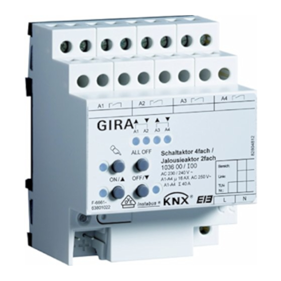
Installation, electrical connection and operation 2.2 Device components Figure 1: Switching / blind actuator 2/4gang Figure 2: Switching / blind actuator 4/8gang Order No. 1036 00 Page 5 of 149 Order No. 1037 00 Order No. 1038 00... - Page 6 LED flashing slowly: output in manual control LED flashing quickly: output blocked by manual control (6) Mains voltage terminal for power supply to the device electronics Order No. 1036 00 Page 6 of 149 Order No. 1037 00 Order No. 1038 00...
-
Page 7: Fitting And Electrical Connection
Connecting the power supply for the device electronics Connect the bus (standard bus terminal) and the mains voltage supply as shown in (Figure 4) (connection example). Order No. 1036 00 Page 7 of 149 Order No. 1037 00 Order No. 1038 00... - Page 8 The switching / blind actuator must be set in the ETS to blinds operation for the corresponding output channel (1 x blind output) (this setting also corresponds to the state as supplied). Connect drive motors as shown in (Figure 5) (connection example). Order No. 1036 00 Page 8 of 149 Order No. 1037 00...
- Page 9 Various phase conductors (L1, L2, L3) can be connected to the outputs. i Do not connect any three-phase motors. Figure 6: Electrical connection for loads in switching operation Order No. 1036 00 Page 9 of 149 Order No. 1037 00...
- Page 10 To install the cap: slide the cap backwards until you feel it engage (Figure 8). To remove the cap: Push the cap sideways slightly and pull off toward the front (Figure 8). Figure 8: Installing / removing the protective cap. Order No. 1036 00 Page 10 of 149 Order No. 1037 00...
-
Page 11: Commissioning
Express the measured value as a percentage of the determined blind/shutter travelling time and enter the value in the ETS (cf. software description). i It is wise to perform several time measurements and to take the average of these values. Order No. 1036 00 Page 11 of 149 Order No. 1037 00... - Page 12 After each supply voltage failure (failure of the bus voltage and of the mains voltage) or after programming with the ETS, the actuator therefore automatically performs a reference travel for each output before a new position can be approached. Order No. 1036 00 Page 12 of 149 Order No. 1037 00...
- Page 13 The message is withdrawn (inverted signal value) as soon as a reference movement could be executed. Order No. 1036 00 Page 13 of 149 Order No. 1037 00...
-
Page 14: Operation
Figure 9: Controls and indicators for manual control for switching / blind actuator 2/4gang Figure 10: Controls and indicators for manual control for switching / blind actuator 4/8gang Order No. 1036 00 Page 14 of 149 Order No. 1037 00... - Page 15 Priority levels 4 and 5 can be parameterized in the ETS. The options are then... 4th priority: sun protection function, 5th priority: direct operation via the bus (STEP/MOVE operation, positioning, scenes, central function), Order No. 1036 00 Page 15 of 149 Order No. 1037 00 Order No. 1038 00...
- Page 16 Switching on permanent manual control Manual control is enabled in the ETS. Bus operation or temporary manual control is active. Press the c button for at least 5 s. Order No. 1036 00 Page 16 of 149 Order No. 1037 00...
- Page 17 Additionally the switching state or a travel movement of the selected output is indicated by the status LED "ON/ n" or "OFF/ o" in the button field." Order No. 1036 00 Page 17 of 149 Order No. 1037 00...
- Page 18 An output that has been disabled in manual control can thereafter only be operated in permanent manual control. i If a disabled output is selected in manual control, the LEDs flash twice briefly with a time interval. Order No. 1036 00 Page 18 of 149 Order No. 1037 00 Order No. 1038 00...
-
Page 19: Technical Data
KNX / EIB / VDE Ambient temperature -5 ... +45 °C Storage/transport temperature -25 ... +70 °C Weight Order No. 1036 00 approx. 250 g Order No. 1037 00 approx. 290 g Order No. 1038 00 approx. 460 g Fitting width Order No. - Page 20 For this reason, different electronic ballasts are listed as an example (manufacturer: Osram). Order No. 1036 00 Page 20 of 149 Order No. 1037 00...
-
Page 21: Software Description
Multifunctional switching / shutter Switching, shutter/ application. blind 208002 for ETS 2 and ETS 3.0a…c Switching, shutter/ blind 208012 for ETS3.0 version d onwards Order No. 1036 00 Page 21 of 149 Order No. 1037 00 Order No. 1038 00... - Page 22 Multifunctional switching / shutter Switching, shutter/ application. blind 207802 for ETS 2 and ETS 3.0a…c Switching, shutter/ blind 207812 for ETS3.0 Version d onwards Order No. 1036 00 Page 22 of 149 Order No. 1037 00 Order No. 1038 00...
-
Page 23: Software "Switching, Shutter/Blind 20Ca11 / 2078X2 / 2080X2
Disabling function can be parameterized for each channel. Alternative forced position function separate for each output (forced position function for switching / blind actuator 8/16 gang only available with ETS3.0d and higher). Order No. 1036 00 Page 23 of 149 Order No. 1037 00... - Page 24 Timing functions (switch-on delay, switch-off delay, staircase lighting timer, also with pre- warning function) Up to 8 internal scenes are configurable (for switching / blind actuator 8/16 gang only available with ETS3.0d and higher). Order No. 1036 00 Page 24 of 149 Order No. 1037 00 Order No. 1038 00...
-
Page 25: Notes On Software
Unloading the application program The application program can be unloaded with the ETS. In this case, manual control as part of the application program is not available either. Order No. 1036 00 Page 25 of 149 Order No. 1037 00... -
Page 26: Object Table
1-bit object for central actuation (long-time movement) of assigned Venetian blind outputs. The polarity can be configured. 1: Each communication object can be read out. For reading, the R-flag must be set. Order No. 1036 00 Page 26 of 149 Order No. 1037 00... - Page 27 1-bit object for central switching of assigned switching outputs. The polarity can be configured. 1: Each communication object can be read out. For reading, the R-flag must be set. Order No. 1036 00 Page 27 of 149 Order No. 1037 00...
- Page 28 2: Depending on the configuration, feedback objects are either actively transmitting (T flag set) or passively readable (R flag set). 3: The number of outputs or communication objects depends on the planned device. Order No. 1036 00 Page 28 of 149 Order No. 1037 00...
- Page 29 2: Each communication object can be read out. For reading, the R-flag must be set. 3: The communication flags are set automatically depending on the configuration. "T" flag for active signalling object; "R" flat for passive status object. Order No. 1036 00 Page 29 of 149 Order No. 1037 00...
- Page 30 2: Each communication object can be read out. For reading, the R-flag must be set. 3: The object designation varies with the type of blind (Venetian blind, roller shutter / awning, venting louver). Order No. 1036 00 Page 30 of 149 Order No. 1037 00...
- Page 31 4: The communication flags are set automatically depending on the configuration. "T" flag for active signalling object; "R" flat for passive status object. Order No. 1036 00 Page 31 of 149 Order No. 1037 00 Order No. 1038 00...
- Page 32 2: The number of outputs or communication objects depends on the planned device. 3: Each communication object can be read out. For reading, the R-flag must be set. Order No. 1036 00 Page 32 of 149 Order No. 1037 00...
-
Page 33: Functional Description
Enable the central function on parameter page "General switching outputs" by setting the "Central function for switching outputs ?" to "Yes". If a function is active, the "Central switching" communication object is visible. Order No. 1036 00 Page 33 of 149 Order No. 1037 00... - Page 34 It should be noted that the switching / blind actuator can compute positions after application of the supply voltage only if a reference movement into the upper limit positions has been performed beforehand. Order No. 1036 00 Page 34 of 149 Order No. 1037 00...
- Page 35 As an active message object, the collective feedback information is transmitted to the bus whenever a switching state changes. As a passive status object, there is no telegram Order No. 1036 00 Page 35 of 149 Order No. 1037 00...
- Page 36 The operation of the function keys, the control of the outputs and the status display are described in detail in chapter "2.5 Manual control". The parameterisation, status feedback, disabling via a bus telegram, and interaction with other Order No. 1036 00 Page 36 of 149 Order No. 1037 00...
- Page 37 Switching states of switching outputs will be maintained. Order No. 1036 00 Page 37 of 149 Order No. 1037 00...
- Page 38 The manual control mode during bus operation must be enabled in the ETS. Set the parameter "Disabling function ?" on parameter page "Manual control" to "yes". Order No. 1036 00 Page 38 of 149 Order No. 1037 00...
- Page 39 The function for disabling the bus control is enabled and can be activated locally. As an alternative, this parameter can be set to "no" to prevent activation of disabling of the bus control in permanent manual control. Order No. 1036 00 Page 39 of 149 Order No. 1037 00...
- Page 40 '23 hours 59 minutes' can be separately selected in the ETS. A shared time is configured for the wind alarms. Each wind alarm has its own timer so that the wind objects are separately checked for telegram updates. Order No. 1036 00 Page 40 of 149 Order No. 1037 00...
- Page 41 (parameter "Behaviour after bus or mains voltage return"). After such action, the outputs are, however, safety-locked and cannot be operated via the bus anymore unless the safety functions assigned are terminated. Order No. 1036 00 Page 41 of 149 Order No. 1037 00...
- Page 42 The cycle time of the transmitters should be shorter than the monitoring time parameterized in the switching/shutter actuator in order to ensure that at least one telegram can be received during the monitoring time. Order No. 1036 00 Page 42 of 149 Order No. 1037 00...
- Page 43 Consequently, parameter settings or group address assignments to objects can be lost. For this reason, the channel definition should be reset when beginning the parameterization of the actuator. Order No. 1036 00 Page 43 of 149 Order No. 1037 00...
-
Page 44: Channel-Oriented Functional Description
The preferred relay contact positions after bus voltage return or after ETS programming can be preset separately for each output. Since the actuator is equipped with mains-dependent monostable relays, the relay switching state at bus voltage failure can be defined as well. Order No. 1036 00 Page 44 of 149 Order No. 1037 00... - Page 45 The state of an output can thereby still change even after a bus failure. Order No. 1036 00 Page 45 of 149 Order No. 1037 00...
- Page 46 In the setting "State before bus/mains voltage failure": An ETS programming operation of the application or the parameter resets the internally stored switching state to "off - 0". Order No. 1036 00 Page 46 of 149 Order No. 1037 00...
- Page 47 "Ax - General" ( x = number of output). Preset parameter to "do not invert, active message object" or "invert, active message object". Order No. 1036 00 Page 47 of 149 Order No. 1037 00 Order No. 1038 00...
- Page 48 Cyclical transmission is activated. Set the parameter "Cyclical transmission of feedback telegram?" on parameter page "Ax General" (x = number of output) to "No". Order No. 1036 00 Page 48 of 149 Order No. 1037 00 Order No. 1038 00...
- Page 49 / forced-control position function) and the output switched off, only after the OFF- delay has elapsed. An ON-telegram received during the OFF-delay will end the delay. The logical switching state corresponds in this case to "switched on". Order No. 1036 00 Page 49 of 149 Order No. 1037 00...
- Page 50 The staircase function can be extended by means of a separate switch-on delay and pre- warning function. The pre-warning function should, according to DIN 18015-2, warn any person still on the staircase that the light will soon be switched off. Order No. 1036 00 Page 50 of 149 Order No. 1037 00...
- Page 51 Taking into account any possible switch-on delay and pre-warning function, this gives rise to the switch-off behaviour of the staircase function as shown in the following diagram. Order No. 1036 00 Page 51 of 149 Order No. 1037 00...
- Page 52 ). The pre-warning time influences the value of the feedback object so that the value "0" (in the case of non-inverted transmission) is first tracked after the pre-warning time in the feedback object has elapsed. Order No. 1036 00 Page 52 of 149 Order No. 1037 00...
- Page 53 During automatic starting of the staircase function after bus/mains voltage return, no switch-on delay is started if the staircase function has configured such a delay. Order No. 1036 00 Page 53 of 149 Order No. 1037 00...
- Page 54 Figure 23: Function diagram of the scene function Order No. 1036 00 Page 54 of 149 Order No. 1037 00 Order No. 1038 00...
- Page 55 Set the parameter "Scene x activatable by scene number" (x = number of the scene (1…8)) for each scene on parameter page "Ax – Scenes" to the numbers with which the scenes are to be addressed. Order No. 1036 00 Page 55 of 149 Order No. 1037 00...
- Page 56 Additionally, a logic operation function can be parameterized. These supplementary functions are enabled on parameter page "Ax – Supplementary functions " (x = number of output). Order No. 1036 00 Page 56 of 149 Order No. 1037 00 Order No. 1038 00...
- Page 57 "ON 1". On the parameter page "Ax - supplementary functions", set the parameter "setting the behaviour at the end of the disabling function" to the required behaviour. Order No. 1036 00 Page 57 of 149 Order No. 1037 00...
- Page 58 The first bit (bit 0) of the "Forced position" object specifies the switching state to be forced. The second bit (bit 1) of the object activates or deactivates the forced-position state (see table 1). Order No. 1036 00 Page 58 of 149 Order No. 1037 00...
- Page 59 "Ax – General" on mains voltage return. i After programming the application or parameters with the ETS, the forced position function is always deactivated (object value "0"). Order No. 1036 00 Page 59 of 149 Order No. 1037 00...
- Page 60 "switching" object. On the parameter page "Ax - supplementary functions", set the parameter "Logic operation function" to "Yes". auf "Ja" einstellen. Order No. 1036 00 Page 60 of 149 Order No. 1037 00...
- Page 61 A mains voltage return does not influence the communication of the logic operations The objects remain on the last set state if the bus voltage was connected interruption free. Order No. 1036 00 Page 61 of 149 Order No. 1037 00...
-
Page 62: Functional Description Of The Venetian Blind Outputs
After programming with the ETS, the actuator raises the blind or opens the venting louvre. Set the parameter to "lowering" or "closing the louver". After programming with the ETS, the actuator lowers the blind or closes the venting louvre. Order No. 1036 00 Page 62 of 149 Order No. 1037 00... - Page 63 (if the mains voltage is on and if manual control is enabled) or by bus/mains voltage return. Order No. 1036 00 Page 63 of 149 Order No.
- Page 64 Set the parameter to "raising" or "opening the louver". After bus or mains voltage return, the actuator raises the curtain or opens the venting louvre. Order No. 1036 00 Page 64 of 149 Order No. 1037 00 Order No. 1038 00...
- Page 65 If just the bus or mains voltage fails after an ETS download and is then restored, the actuator executes the "Behaviour after bus or mains voltage return". Order No. 1036 00 Page 65 of 149 Order No. 1037 00...
- Page 66 Therefore, it is recommended to make several time measurements and to take the average of these values before entering them into the corresponding parameter. Order No. 1036 00 Page 66 of 149 Order No. 1037 00...
- Page 67 The actuator assumes that the slats are completely closed when the Venetian blind moves downwards (Figure 29). These Venetian blinds are the most common type on the market. Order No. 1036 00 Page 67 of 149 Order No. 1037 00...
- Page 68 The movement time extension should be determined separately for each output during commissioning and entered into the ETS configuration. The measurement of the movement time extension is described in detail in chapter "Commissioning". Order No. 1036 00 Page 68 of 149 Order No. 1037 00 Order No. 1038 00...
- Page 69 The calculated position value is a measure of the height of the blind or of the opening width of the venting louver (Figure 31). Order No. 1036 00 Page 69 of 149 Order No.
- Page 70 11 s and thus position it at a blind height of 25 %. When the lower or upper end positions (0 % or 100 %) are approached, the movement time is always 20 % longer than the overall movement time. Order No. 1036 00 Page 70 of 149 Order No. 1037 00...
- Page 71 (Figure 32). Figure 32: Example of slat positioning affecting the position of the Venetian blind (typical of slat type 1; analogous reaction for type 2) Order No. 1036 00 Page 71 of 149 Order No. 1037 00 Order No. 1038 00...
- Page 72 (0 to 100 %). i The switching / blind actuator executes slat position adjustments only if a new position deviating from the current slat position is preset. Order No. 1036 00 Page 72 of 149 Order No. 1037 00...
- Page 73 0 % position, a manually controlled movement into the upper end position. Figure 34: Reference movement Order No. 1036 00 Page 73 of 149 Order No. 1037 00 Order No. 1038 00...
- Page 74 ↓ (all intermediate values rounded off to 1 % increments) 100 % lower end position / slat or louvre closed) Table 2: Data format of positioning objects with conversion into percentage position values Order No. 1036 00 Page 74 of 149 Order No. 1037 00...
- Page 75 The positions are tracked and the feedback objects updated even when an output has been activated via short-time or long-time telegrams or by manual control on condition that the bus voltage is on. Order No. 1036 00 Page 75 of 149 Order No. 1037 00...
- Page 76 If a time delay after bus voltage return should be necessary, the parameter "Time delay for feedback after bus voltage return" on parameter page "Ax – Feedbacks" must be set to "yes" Order No. 1036 00 Page 76 of 149 Order No. 1037 00...
- Page 77 In case of Venetian blind operation, any position change of the Venetian blind within the limits of the slat adjustment (0 to 100 %) does not launch a movement and therefore no change of the feedback position data either. Order No. 1036 00 Page 77 of 149 Order No. 1037 00...
- Page 78 Set the parameter "Invalid blind position feedback", "Invalid shutter/awning position feedback" or "invalid venting louver position feedback" on parameter page "Ax – Feedbacks" to "feedback object is active signalling object" Order No. 1036 00 Page 78 of 149 Order No. 1037 00...
- Page 79 After the end of the time delay, the object value state last adjusted will be transmitted to the bus. No feedback telegram is transmitted during a running delay, even if the drive stops or starts moving. Order No. 1036 00 Page 79 of 149 Order No. 1037 00...
- Page 80 At the end of a forced position or of a manual control, the safety reaction is re-executed if an assigned safety alarm is still active. Order No. 1036 00 Page 80 of 149 Order No. 1037 00...
- Page 81 The actuator lowers the curtain or closes the venting louver at the beginning of the alarm and locks the output thereafter. Set the parameter "Behaviour in case of ..." to "stop". Order No. 1036 00 Page 81 of 149 Order No. 1037 00...
- Page 82 If a sun protection function is activated (independent of the preset priority with respect to direct operation), it will be also executed. Order No. 1036 00 Page 82 of 149 Order No.
- Page 83 After ETS programming or after switch-on of the supply voltage, the object must at first have data written into it by the bus also in case of inverted polarity before the sun protection can be activated. Order No. 1036 00 Page 83 of 149 Order No. 1037 00...
- Page 84 The schematic diagram of the sun protection (Figure 37) is intended to illustrate, for example, how sensor components can be integrated into a simple sun protection configuration. Figure 37: Schematic diagram illustrating of the sun protection configuration Order No. 1036 00 Page 84 of 149 Order No. 1037 00...
- Page 85 Set the parameter "Priority of sun protection with respect to direct operation" on parameter page "Ax - Sun protection" to "lower priority". Order No. 1036 00 Page 85 of 149 Order No. 1037 00...
- Page 86 For the sun protection parameters to be visible, the sun protection function must be enabled on parameter page "Ax – Enabled functions (x = number pair of output). Order No. 1036 00 Page 86 of 149 Order No. 1037 00...
- Page 87 Set the parameter "Reaction at the beginning of sunshine / shading" to "fixed position". At the beginning of shading, the switching / blind actuator recalls a fixed position value for the output concerned. Order No. 1036 00 Page 87 of 149 Order No. 1037 00...
- Page 88 The position data last received are not lost during a failure of the bus voltage (mains supply voltage is on). Order No. 1036 00 Page 88 of 149 Order No. 1037 00 Order No. 1038 00...
- Page 89 "Venetian Blind" operating mode: A terminated reference movement of for the height of the Venetian blind synchronises at the same time also the slat position. Order No. 1036 00 Page 89 of 149 Order No. 1037 00...
- Page 90 An offset preset via the object overwrites the value configured in the ETS. In the event of a bus voltage failure or a mains voltage failure of the actuator, an offset value received via the Order No. 1036 00 Page 90 of 149 Order No.
- Page 91 'visible' correction of the offset angle by the output. i After an ETS programming operation, the offset is always set to the value configured in the ETS. Order No. 1036 00 Page 91 of 149 Order No. 1037 00...
- Page 92 Known slat positions will also be tracked as described. This is also the case, when the height of the Venetian blind is unknown. Long time travel movements (movements without position preset) will always be tracked. Order No. 1036 00 Page 92 of 149 Order No. 1037 00...
- Page 93 The present chapter describes different applications of the sun protection function of the switching / blinds actuator in combination with the Gira KNX/EIB weather station (order no. 1010 00) and the combination sensor (order no. 1025 00). The following section contains sketches for each application of which communication objects of the weather station should be connected with the switching / blind actuator.
- Page 94 - Reaction at beginning of sun / shading = Venetian blind position fixed / slat position variable, - Configure fixed position of Venetian blind. Figure 42: Programming of the communication objects for application example III Order No. 1036 00 Page 94 of 149 Order No. 1037 00 Order No. 1038 00...
- Page 95 - Reaction at beginning of sun / shading = Venetian blind position variable, slat position variable, Figure 43: Programming of the communication objects for application example IV Order No. 1036 00 Page 95 of 149 Order No. 1037 00 Order No. 1038 00...
- Page 96 "Ax - Enabling functions" (x = number pair of output) for each output in order for the required communication objects and parameters (on the parameter page "Ax - Scenes") to be visible. Order No. 1036 00 Page 96 of 149 Order No.
- Page 97 Scene values stored in the device with a storage function will be maintained. If no scene values have been stored, the position values last programmed in the ETS remain valid. Order No. 1036 00 Page 97 of 149 Order No. 1037 00...
- Page 98 "Ax – Enabled functions (x = number pair of output). Set the parameter "Storage function for scene y" (y = number of the scene (1…8) on parameter page "Ax – Scenes" for each scene to "yes". Order No. 1036 00 Page 98 of 149 Order No. 1037 00...
- Page 99 A mains failure alone (bus voltage present) has no effect on the state of the forced-position object. If only the mains voltage return, a previously activated forced position remains active. Order No. 1036 00 Page 99 of 149 Order No. 1037 00...
- Page 100 At the end of forced position function, the state last adjusted will not be changed. Thereafter, the output is again enabled. Any movements still in progress at this instant will still be finished. Order No. 1036 00 Page 100 of 149 Order No. 1037 00...
- Page 101 Set the parameter "Behaviour after bus voltage return" to "state of forced position before bus/mains failure". Order No. 1036 00 Page 101 of 149 Order No. 1037 00 Order No. 1038 00...
- Page 102 "Ax – Enabled functions" (x = number pair of output). The operating mode selected must be the "Roller shutter/awning" mode. Set the parameter "Fabric stretching function" to "enabled". Order No. 1036 00 Page 102 of 149 Order No. 1037 00...
- Page 103 Otherwise, there is the risk of malfunction. i Fabric stretching will only be effected if the downward movement lasts longer than the configured fabric stretching time. Order No. 1036 00 Page 103 of 149 Order No. 1037 00...
-
Page 104: Delivery State
Break during movement direction changeover: 1 s Behaviour in case of bus voltage failure: no reaction Behaviour after bus or mains voltage return: Stop Order No. 1036 00 Page 104 of 149 Order No. 1037 00 Order No. 1038 00... -
Page 105: Parameters
(telegram transmission only as a response to a 'Read' request). The communication flags of the object are automatically set by the ETS according to the setting. Order No. 1036 00 Page 105 of 149 Order No. 1037 00 Order No. 1038 00... - Page 106 The parameter "Time for cyclical transmission of feedback tel." generally defines the cycle time for all outputs. Sets the cycle time hours. Order No. 1036 00 Page 106 of 149 Order No. 1037 00 Order No. 1038 00...
- Page 107 (setting: "enabled"). If the frost alarm is deactivated (setting: "disabled"), any programmed assignment of individual shutter outputs to the frost alarm is not operational. Priority of safety alarms Order No. 1036 00 Page 107 of 149 Order No. 1037 00 Order No. 1038 00...
- Page 108 (setting: "yes"). Otherwise (setting: "No") there is no cyclical monitoring of the object. Order No. 1036 00 Page 108 of 149 Order No. 1037 00 Order No. 1038 00...
- Page 109 The times can only be set, if frost alarm monitoring is activated. h Manual operation Order No. 1036 00 Page 109 of 149 Order No. 1037 00 Order No. 1038 00...
- Page 110 If, however, a function with a higher priority was activated as direct operation during manual operation (safety, forced position, sun protection), the actuator Order No. 1036 00 Page 110 of 149 Order No. 1037 00 Order No. 1038 00...
- Page 111 Output 15 definition of the output pair A15 and and output 16** 2 x switching output A16. *: Only for switching / blind actuator 4/8gang Order No. 1036 00 Page 111 of 149 Order No. 1037 00 Order No. 1038 00...
- Page 112 In case of bus voltage failure, the actuator switches the relays of the output to the "stop" position. A drive movement, if any, will be interrupted. Order No. 1036 00 Page 112 of 149 Order No. 1037 00 Order No. 1038 00...
- Page 113 This parameter specifies the venting louvre in case of bus louvre position to be approached in case voltage failure of bus voltage failure. (0...100%) Order No. 1036 00 Page 113 of 149 Order No. 1037 00 Order No. 1038 00...
- Page 114 < 20 s), the "Behaviour after ETS programming" will be adopted also in case of mains voltage return. Venetian blind position 0...100% on bus/mains voltage Order No. 1036 00 Page 114 of 149 Order No. 1037 00 Order No. 1038 00...
- Page 115 The time extension expressed in percent is the difference between the measured travel time needed to reach the lower end position (completely closed position) and Order No. 1036 00 Page 115 of 149 Order No. 1037 00 Order No. 1038 00...
- Page 116 The Minutes (0...59) time needed for a complete travel from the upper into the lower end position Order No. 1036 00 Page 116 of 149 Order No. 1037 00 Order No. 1038 00...
- Page 117 The slat moving time must be selected shorter than the blind travelling time. i These parameters are visible only in the 'Blind' mode of operation. Order No. 1036 00 Page 117 of 149 Order No. 1037 00 Order No. 1038 00...
- Page 118 The venetian blind central function is supposed to have been enabled under "General". The assignment has otherwise no effect on the Venetian blind output. Order No. 1036 00 Page 118 of 149 Order No. 1037 00 Order No. 1038 00...
- Page 119 No feedback object available for the output. Feedback deactivated. Feedback object is Feedback and the object are activated. active signalling object The object transmits actively (telegram transmission after change). Order No. 1036 00 Page 119 of 149 Order No. 1037 00 Order No. 1038 00...
- Page 120 (e.g. after an initialisation, when no reference travel has been executed as yet). no feedback No feedback object available for the output. Feedback deactivated. Order No. 1036 00 Page 120 of 149 Order No. 1037 00 Order No. 1038 00...
- Page 121 This parameter is visible only in the 'Venting louvre' operating mode. Yes (delay time under The feedback telegram can be "General"!) transmitted to the bus with a delay after Order No. 1036 00 Page 121 of 149 Order No. 1037 00 Order No. 1038 00...
- Page 122 Wind alarm 1 + 2 Wind alarm 1 + 3 Wind alarm 2 + 3 Wind alarm 1 + 2 + 3 Behaviour in case of wind alarm Order No. 1036 00 Page 122 of 149 Order No. 1037 00 Order No. 1038 00...
- Page 123 At the beginning of the rain alarm, the actuator switches the relays of the output to "stop" and locks the output. A Order No. 1036 00 Page 123 of 149 Order No. 1037 00 Order No. 1038 00...
- Page 124 The actuator unlocks the output at the louvre end of all safety alarms and raises the curtain or opens the venting louver. Lowering / closing the louvre Order No. 1036 00 Page 124 of 149 Order No. 1037 00 Order No. 1038 00...
- Page 125 Polarity of the sunshine = 1; no This parameter defines the polarity of "Sunshine / shading fac- sunshine = 0 the input object ade" object Order No. 1036 00 Page 125 of 149 Order No. 1037 00 Order No. 1038 00...
- Page 126 At the beginning of shading, the output Venetian blind position controls the approach to a configured variable fixed slat position and to a Venetian Order No. 1036 00 Page 126 of 149 Order No. 1037 00 Order No. 1038 00...
- Page 127 At the beginning of shading, the actuator closes the venting louvre. stop At the beginning of shading, the actuator switches the relays of the output to the Order No. 1036 00 Page 127 of 149 Order No. 1037 00 Order No. 1038 00...
- Page 128 (0...100 %) the slat to be approached at the beginning of shading and, as the case may be, after positioning of the Venetian blind. Order No. 1036 00 Page 128 of 149 Order No. 1037 00 Order No. 1038 00...
- Page 129 This parameter is only visible if the venting louvre is to approach a fixed position at the beginning of shading. Order No. 1036 00 Page 129 of 149 Order No. 1037 00 Order No. 1038 00...
- Page 130 Even with offset correction, the 0...100% slat position limits cannot be overstepped. Order No. 1036 00 Page 130 of 149 Order No. 1037 00 Order No. 1038 00...
- Page 131 Sets the delay time minutes. Seconds (0...59) 0...30...59 Sets the delay time seconds. Presetting: 30 seconds Order No. 1036 00 Page 131 of 149 Order No. 1037 00 Order No. 1038 00...
- Page 132 A recall delay has no influence on the storage of scene values. Delay time 0...59 This parameter is used for setting the Minutes (0...59) duration of the scene delay. Order No. 1036 00 Page 132 of 149 Order No. 1037 00 Order No. 1038 00...
- Page 133 *: The predefined position which is executed when the scene is X = depending on the value is dependent on the recalled. scene (1...8) scene (1...8). Order No. 1036 00 Page 133 of 149 Order No. 1037 00 Order No. 1038 00...
- Page 134 After bus voltage return, the forced before bus/mains failure position state last selected and internally stored before bus or mains voltage Order No. 1036 00 Page 134 of 149 Order No. 1037 00 Order No. 1038 00...
- Page 135 ETS programming separately for each output. close contact The relay contact closes after an ETS programming operation open contact Order No. 1036 00 Page 135 of 149 Order No. 1037 00 Order No. 1038 00...
- Page 136 When the staircase function is not enabled, there is no reaction after bus or mains voltage return with this setting. Order No. 1036 00 Page 136 of 149 Order No. 1037 00 Order No. 1038 00...
- Page 137 The state is transmitted inverted. The object transmits actively (telegram transmission after change). inversion, passive status Feedback and the object are activated. object The state is transmitted inverted. The Order No. 1036 00 Page 137 of 149 Order No. 1037 00 Order No. 1038 00...
- Page 138 / Only visible in switching operation and only accessible if parameter "Time delays ?" under "Ax – Enabled functions" is set to "enabled"!) Order No. 1036 00 Page 138 of 149 Order No. 1037 00...
- Page 139 Ax – Staircase function (x = number of output A1 … max. A16 in switching operation / All outputs can be parameterized independent of one another. / Only visible in switching operation Order No. 1036 00 Page 139 of 149 Order No.
- Page 140 Sets the switch-on delay hours. Minutes (0...59) 0...59 Sets the switch-on delay minutes. Seconds (0...59) 0...30...59 Sets the switch-on delay seconds. Presetting: 30 seconds Order No. 1036 00 Page 140 of 149 Order No. 1037 00 Order No. 1038 00...
- Page 141 The time should be customized individually to the switch-off behaviour of the lamp used. Sets the pre-warning interruption seconds. 0...5...9 Order No. 1036 00 Page 141 of 149 Order No. 1037 00 Order No. 1038 00...
- Page 142 (setting: "No"). As an alternative, the original values can be reloaded into the device during each Order No. 1036 00 Page 142 of 149 Order No. 1037 00 Order No. 1038 00...
- Page 143 ("1 = enabled; 0 = disabled"), a telegram update "0" must first be carried out after the initialisation until the disabling is activated. Order No. 1036 00 Page 143 of 149 Order No. 1037 00 Order No. 1038 00...
- Page 144 The flashing continues until a new switching state is specified. The flashing time is configured generally Order No. 1036 00 Page 144 of 149 Order No. 1037 00 Order No. 1038 00...
- Page 145 Response to bus The forced position communication voltage return object can be initialised after bus voltage return. The switching state of the output Order No. 1036 00 Page 145 of 149 Order No. 1037 00 Order No. 1038 00...
- Page 146 1 (ON) here with the preset value. return i This parameter is only visible when the logic operation function is enabled. Order No. 1036 00 Page 146 of 149 Order No. 1037 00 Order No. 1038 00...
- Page 147 This parameter is only visible when the logic operation function is enabled. Order No. 1036 00 Page 147 of 149 Order No. 1037 00 Order No. 1038 00...
-
Page 148: Appendix
Position feedback ........75 Presetting the mode of operation ..62 Presetting the position ......74 Presetting the STEP operation ....66 Order No. 1036 00 Page 148 of 149 Order No. 1037 00 Order No. 1038 00... - Page 149 Systeme Industriegebiet Mermbach Dahlienstraße 42477 Radevormwald Postfach 12 20 42461 Radevormwald Deutschland Tel +49(0)21 95 - 602-0 Fax +49(0)21 95 - 602-191 www.gira.de info@gira.de Order No. 1036 00 Page 149 of 149 Order No. 1037 00 Order No. 1038 00...
Need help?
Do you have a question about the 1036 00 and is the answer not in the manual?
Questions and answers