Table of Contents
Advertisement
Quick Links
Advertisement
Table of Contents

Related Manuals for Gira KNX 213900


Summary of Contents for Gira KNX 213900
- Page 1 Operating instructions Heating actuator 6-gang with controller Order no. 2139 00...
-
Page 2: Table Of Contents
Heating actuator 6-gang with controller Table of Contents Safety instructions ...................... 3 Device components...................... 4 Function .......................... 5 Operation .......................... 7 As-delivered state ...................... 10 Information for electrically skilled persons .............. 11 Mounting and electrical connection.............. 11 Commissioning .................... 13 6.2.1 Safe-state mode and master reset ............ 13 Technical data ......................... 15 Troubleshooting ...................... 16 Warranty.......................... 17... -
Page 3: Safety Instructions
Heating actuator 6-gang with controller Safety instructions Electrical devices may only be mounted and connected by electrically skilled persons. Serious injuries, fire or property damage possible. Please read and follow manual fully. Danger of electric shock. Always disconnect before carrying out work on the device or load. -
Page 4: Device Components
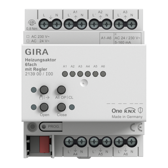
Heating actuator 6-gang with controller Device components Image 1: Front view Supply of electrothermal valve drives Connection of electrothermal valve drives (A1 to A6) Status LEDs for outputs Button field for manual operation Programming button and LED Bus connection If all of the status LEDs (3) are flashing (2 Hz), the device is indicating that there is no power supply to the electrothermal valve drives (1). -
Page 5: Function
The device can be updated. Firmware can be easily updated with the Gira ETS Ser- vice App (additional software). The device is KNX Data Secure capable. KNX Data Secure offers protection against manipulation in building automation and can be configured in the ETS project. - Page 6 Heating actuator 6-gang with controller – Integrated room temperature control with setpoint value specification – 12 independent controllers to control up to 12 independent rooms – Controller function for heating and cooling operation Overload / short-circuit protection In order to protect the device and connected valve drives, in case of overload or short-circuit the device determines which output is involved and switches it off.
-
Page 7: Operation
Heating actuator 6-gang with controller Operation Image 2: Operating elements Status LEDs for outputs Button ǃ – Manual operation LED - On: permanent manual operation mode active Open button – Open valve LED – On: valve opened, manual operation mode Close button – Close valve LED –... - Page 8 Heating actuator 6-gang with controller Switching on temporary manual operation mode Operation is not disabled. ■ Press the ǃ button briefly. Status LED A1 flashes, LED ǃ flashes. After 5 seconds without button actuation, the actuator returns automatically to bus mode. Switching off temporary manual operation mode The device is in temporary manual operation mode.
- Page 9 Heating actuator 6-gang with controller The LEDs Open and Close indicate the valve status. Temporary manual operation mode: After running through all of the outputs the device exits manual operation mode after another brief actuation. Operating all outputs simultaneously The device is in permanent manual operation mode. ■...
-
Page 10: As-Delivered State
Heating actuator 6-gang with controller As-delivered state In the as-delivered state, the device enables manual operation on the device itself, provided that the voltage supply to the valve drives and the bus voltage are switched on. With manual operation, no feedback telegrams are sent to the KNX. In the as-delivered state, all the valve outputs are configured as follows: –... -
Page 11: Information For Electrically Skilled Persons
Heating actuator 6-gang with controller Information for electrically skilled persons Mounting and electrical connection DANGER! Mortal danger of electric shock. Disconnect the device. Cover up live parts. Mounting the device – Enter or scan the device certificate and add it to the project. A high resolution camera should be used to scan the QR code. - Page 12 Heating actuator 6-gang with controller Image 3: Connection of 230 V valve drives ■ Connect AC 24 V valve drives according to the connection diagram (see figure 4). Image 4: Connection of 24 V valve drives ■ Connect the supply for the valve drives to the terminals 8(L) and 8(N) (1). ■...
-
Page 13: Commissioning
Heating actuator 6-gang with controller Commissioning The device is commissioned with the ETS version 5.7.7 or higher. 6.2.1 Safe-state mode and master reset Safe-state mode The safe-state mode stops the execution of the loaded application program. Only the system software of the device is still functional. ETS diagnosis func- tions and programming of the device are possible. - Page 14 Heating actuator 6-gang with controller Restoring the device to factory settings The device can be reset to factory settings with the Gira ETS Service App. This func- tion uses the firmware contained in the device that was active at the time of delivery (as-delivered state).
-
Page 15: Technical Data
Heating actuator 6-gang with controller Technical data KNX medium TP256 Commissioning mode S-mode Rated voltage KNX DC 21 ... 32 V SELV Current consumption KNX 4.5 ... 10 mA Heating outputs Contact type Semi-conductor (Triac), ε Switching voltage AC 24 / 230 V ~ Mains frequency 50 / 60 Hz Switching current... -
Page 16: Troubleshooting
Heating actuator 6-gang with controller Troubleshooting Valve drives of an output or all outputs do not switch Cause: An output is overloaded. Determine cause of the overload switch-off. Eliminate short-circuits, replace de- fective valve drives. Check number of valve drives connected to the output, re- duce if necessary. -
Page 17: Warranty
Please submit or send faulty devices postage paid together with an error de- scription to your responsible salesperson (specialist trade/installation company/elec- trical specialist trade). They will forward the devices to the Gira Service Center. Gira Giersiepen GmbH & Co. KG...
Need help?
Do you have a question about the KNX 213900 and is the answer not in the manual?
Questions and answers