
Related Manuals for Gira 0309 00


Summary of Contents for Gira 0309 00
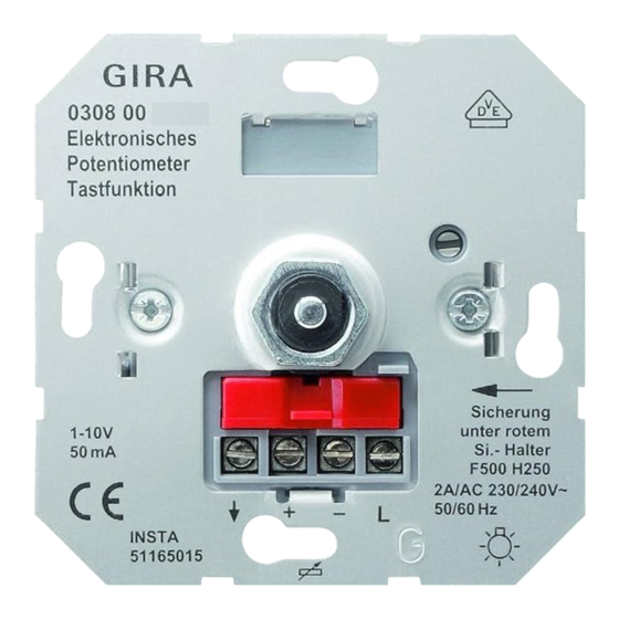
- Page 1 Operating instructions Electronic potentiometer insert for 1-10 V control input, switching function Order no. 0309 00...
- Page 2 Electronic potentiometer insert for 1-10 V control input, switching function Table of Contents Safety instructions ...................... 3 Device components ...................... 3 Intended use ........................ 3 Product characteristics ..................... 4 Operation .......................... 4 Information for electrically skilled persons ................ 4 Commissioning ......................... 6 Technical data ........................
- Page 3 Electronic potentiometer insert for 1-10 V control input, switching function Safety instructions Electrical devices may be mounted and connected only by electrically skilled persons. Serious injuries, fire or property damage are possible. Please read and follow the manual fully. Danger of electric shock. Device is not suitable for disconnection from supply voltage.
- Page 4 Electronic potentiometer insert for 1-10 V control input, switching function – Mounting in appliance box with dimensions according to DIN 49073 Product characteristics – Basic brightness adjustable – Short-circuit protection of switching contact with integrated fine-wire fuse Operation Switching electronic operating devices on or off ■...
- Page 5 Electronic potentiometer insert for 1-10 V control input, switching function Connecting and fitting the device Image 2: Connection diagram - Potentiometer switches the lamp operating devices directly Image 3: Connection diagram - Potentiometer and contactor for switching the lamp operating devices Electronic potentiometer Lamp operating device with 1-10 V interface, electronic ballast Control cable: appropriate type, cross-section and routing for the VDE specific- ations for 250 V cables, control voltage has basic insulation.
- Page 6 Electronic potentiometer insert for 1-10 V control input, switching function CAUTION! Device defect when the 1-10 V interface is connected to mains voltage Do not connect 1-10 V interface to mains voltage. ■ Connect electronic potentiometer with switching function according to connec- tion diagram (see figure 2) or (see figure 3).
- Page 7 Please submit or send faulty devices postage paid together with a fault de- scription to your responsible salesperson (specialist trade / installation company / electrical specialist trade). They will forward the devices to the Gira Service Center. Gira Giersiepen GmbH & Co. KG...
Need help?
Do you have a question about the 0309 00 and is the answer not in the manual?
Questions and answers