
Subscribe to Our Youtube Channel
Related Manuals for Gira KNX 5062 00


Summary of Contents for Gira KNX 5062 00
- Page 1 Operating instructions Switching actuator 2-gang / blind actuator, 1-gang 16 A with binary input, 3-gang Order no. 5062 00...
-
Page 2: Table Of Contents
Switching actuator 2-gang / blind actuator, 1-gang 16 A with binary input, 3-gang Table of Contents Safety instructions ...................... 3 Device components...................... 4 Function .......................... 5 Information for electrically skilled persons ................ 7 Mounting and electrical connection................ 7 Commissioning ...................... 9 Technical data ......................... 11 Accessories ........................ 13 Warranty.......................... 13 82404232... -
Page 3: Safety Instructions
Switching actuator 2-gang / blind actuator, 1-gang 16 A with binary input, 3-gang Safety instructions Electrical devices may only be mounted and connected by electrically skilled persons. Serious injuries, fire or property damage possible. Please read and follow manual fully. Danger of electric shock. -
Page 4: Device Components
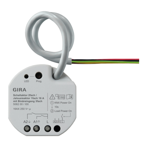
Switching actuator 2-gang / blind actuator, 1-gang 16 A with binary input, 3-gang Device components Image 1: Device components Programming LED Programming button Control cable (KNX connection and extension inputs) Connection of load (relay outputs) Image 2: Connection assignment of control cable (example) red (RD) KNX + black (BK) -
Page 5: Function
The device can be updated. Firmware can be easily updated with the Gira ETS Ser- vice App (additional software). The device is KNX Data Secure capable. KNX Data Secure offers protection against manipulation in building automation and can be configured in the ETS project. - Page 6 Switching actuator 2-gang / blind actuator, 1-gang 16 A with binary input, 3-gang Characteristics switch operation – Operation as NO or NC contacts – Feedback function – Logic and restraint function – Central switching functions with collective feedback – Time functions: switch-on delay, switch-off delay, staircase lighting timer with run-on time –...
-
Page 7: Information For Electrically Skilled Persons
Switching actuator 2-gang / blind actuator, 1-gang 16 A with binary input, 3-gang – Limit value switch Information for electrically skilled persons DANGER! Mortal danger of electric shock. Disconnect the device. Cover up live parts. Mounting and electrical connection DANGER! When connecting the bus/extensions and mains voltage wires in a shared appliance box, the KNX bus line may come into contact with the mains voltage. - Page 8 Switching actuator 2-gang / blind actuator, 1-gang 16 A with binary input, 3-gang Image 3: Mounting example in electronic appliance box with partition wall, series push-button and NTC temperature sensor Appliance box Partition potential-free contacts (e.g. series push-button) NTC temperature sensor (optional) Image 4: Cable spacing Minimum spacing between the mains voltage and bus/extension wires: 4 mm (see figure 4)
-
Page 9: Commissioning
Switching actuator 2-gang / blind actuator, 1-gang 16 A with binary input, 3-gang Image 5: Connection of load Observe ambient temperature. Ensure adequate cooling. ■ Connect bus line, observing the correct polarity. ■ Connect load as shown in the connection example (see figure 5). ■... - Page 10 Switching actuator 2-gang / blind actuator, 1-gang 16 A with binary input, 3-gang ■ Switch on the KNX bus voltage. ■ Wait about 10 s. ■ Connect the load circuit. Delivery state: The output is set as a Venetian blind output. Operation of the blind output possible via input 1 (UP) and input 2 (DOWN).
-
Page 11: Technical Data
5 s. Restoring the device to factory settings Devices can be reset to factory settings with the Gira ETS Service App. This function uses the firmware contained in the device that was active at the time of delivery (de- livered state). - Page 12 Switching actuator 2-gang / blind actuator, 1-gang 16 A with binary input, 3-gang Fluorescent lamps Σ 16 AX Switch-on current 200 μs max. 800 A Switch-on current 20 ms max. 165 A Power consumption per output Ohmic load 2500 W Capacitive load max.
-
Page 13: Accessories
Please submit or send faulty devices postage paid together with an error de- scription to your responsible salesperson (specialist trade/installation company/elec- trical specialist trade). They will forward the devices to the Gira Service Center. Gira Giersiepen GmbH & Co. KG...
Need help?
Do you have a question about the KNX 5062 00 and is the answer not in the manual?
Questions and answers