Table of Contents
Advertisement
Quick Links
Advertisement
Table of Contents

Subscribe to Our Youtube Channel
Related Manuals for Gira 1289 00


Summary of Contents for Gira 1289 00
- Page 1 Operating Instructions Switching actuator 1289 00...
-
Page 3: Table Of Contents
Table of contents Device description ............4 Operating elements and indicators ......5 Connection terminals ........... 7 Mounting ..............8 Setting operating mode ..........9 Switching operating mode after programming... 10 Information on programming ........11 "Schalten" (Switching) operating mode...... 12 "Timer/sek."... -
Page 4: Device Description
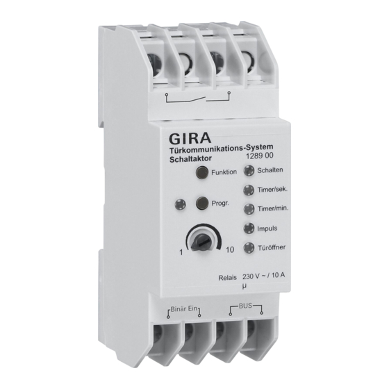
Device description The switching actuator is part of the Gira door communication system. Switching functions operated via the 2-wire bus are executed via the potential- free relay contact of the switching actua- tor. -
Page 5: Operating Elements And Indicators
Operating elements and indicators "Progr." button The "Progr." button has two functions: 1. Starting programming mode of the switching actuator: If the "Progr." but- ton is pressed for 3 seconds while the system is in programming mode, the programming mode of the switching actuator is started. - Page 6 "Funktion" button The required operating mode can be set with the "Funktion" button (see Page 9). The next operating mode is selected with each button press. The LEDs next to the operating mode names indicate the active operating move. LED indication The LEDs only illuminate while the door communication system is in program- ming mode.
-
Page 7: Connection Terminals
The switching actuator is connected to the 2-wire bus via these terminals. Polar- ity need not be taken into account here, as the polarity of the Gira door communi- cation system 2-wire bus is neutral. Binary in One or more mechanical buttons (NO... -
Page 8: Mounting
Mounting Attention Installation and mounting of electrical devices may only be carried out by a qualified electrician. For installation protected from dripping and sprayed water, mount the control unit to a top-hat rail in the distribution. The device connection and bus connec- tion are made via terminal screws. -
Page 9: Setting Operating Mode
Setting operating mode The switching actuator can be used in five different operating modes: • Schalten (Switching, see Page 12) • Timer/sek. (Timer/sec., see Page 14) • Timer/min. (Timer/min., see Page 16) • Impuls (Pulse, see Page 18) • Türöffner (Door opener, see Page 20) Proceed as follows to select the desired operating mode: 1. -
Page 10: Switching Operating Mode After Programming
Switching operating mode after programming If the operating mode of a previously pro- grammed switching actuator was switched, the programming remains in tact. When only switching between switching functions, e.g. from "Schalten" to "Timer/ min.", the switching function with the modified conditions is executed. -
Page 11: Information On Programming
Information on programming Automatic assignment of the switching actuator The switching actuator is automatically assigned to the button of the home stations. If the switching actuator is pro- grammed to a specific button, the auto- matic assignment is lost. • Switching actuator functions must be assigned in a separate programming procedure, i.e. -
Page 12: Schalten" (Switching) Operating Mode
"Schalten" (Switching) operating mode In the "Schalten" operating mode, the device is activated via the press of a but- ton and remains activated until the button is pressed again. The "Schalten" operating mode can be assigned to the following buttons: •... - Page 13 Programming "Schalten" 1. Start programming mode at the control unit by pressing the "System- progr." button for 3 seconds until the LED next to the button starts flashing. ✓ The LED of the last set operating mode flashes at the switching actuator. 2.
-
Page 14: Timer/Sek." Operating Mode
"Timer/sek." operating mode The "Timer/sek." operating mode (1 - 10 s) could be used for direct operation of the door opener of a back/side door, for example. It can then be operated directly, even if no calls were initiated from the back/side door. - Page 15 Programming "Timer/sek." 1. Start programming mode at the control unit by pressing the "System- progr." button for 3 seconds until the LED next to the button starts flashing. ✓ The LED of the last set operating mode flashes at the switching actuator. 2.
-
Page 16: Timer/Min." Operating Mode
"Timer/min." operating mode The "Timer/min." (1 - 10 minutes) operat- ing mode could be used for the operation of path illumination or staircase illumina- tion (without security function), for exam- ple. After the button is pressed, the contact closes according to the set time. The acti- vation time can be set within the range of 1 to 10 seconds via the adjuster. - Page 17 Programming "Timer/min." 1. Start programming mode at the control unit by pressing the "System- progr." button for 3 seconds until the LED next to the button starts flashing. ✓ The LED of the last set operating mode flashes at the switching actuator. 2.
-
Page 18: Impuls" (Pulse) Operating Mode
"Impuls" (Pulse) operating mode The "Impuls" operating mode could be used for the operation of an existing auto- matic staircase mechanism, for example. The contact closes for 0.3 seconds after the button is pressed. The "Impuls" operating mode can be assigned to the following buttons: •... - Page 19 Programming "Impuls" 1. Start programming mode at the control unit by pressing the "System- progr." button for 3 seconds until the LED next to the button starts flashing. ✓ The LED of the last set operating mode flashes at the switching actuator. 2.
-
Page 20: Türöffner" (Door Opener) Operating Mode
"Türöffner" (Door opener) operating mode In the "Türöffner" (1 - 10 seconds) operat- ing mode, the switching actuator of the button of the home station is oper- ated. The activation time of the door opener can be set within the range 1 to 10 seconds via the adjuster. - Page 21 Side/back door opener Control unit Main door opener Assigning door opener of switching actuator 1. Start programming mode at the control unit by pressing the "System- progr." button for 3 seconds until the LED next to the button starts flashing.
- Page 22 ✓ The LED of the last set operating mode flashes at the switching actuator. 2. Press the "Funktion" button at the switching actuator several times until the "Türöffner" LED flashes. 3. Press the "Progr." button at the swit- ching actuator for 3 seconds until the LED next to the button flashes.
-
Page 23: Deleting Assignments Of The Switching Actuator
Deleting assignments of the switching actuator Proceed as follows to delete all existing assignments of the switching actuator: 1. Start programming mode at the control unit by pressing the "System- progr." button for 3 seconds until the LED next to the button starts flashing. ✓... -
Page 24: Application Example "Switching Illumination
Application example "Switching illumination" The illumination (e.g. in the entryway) is to be switched on and off via a call button of the home station and a mechanical but- ton. mech. Button... - Page 25 1. Start programming mode at the control unit by pressing the "System- progr." button for 3 seconds until the LED next to the button starts flashing. ✓ The LED of the last set operating mode flashes at the switching actuator. 2.
-
Page 26: Application Example "Additional Signalling
Application example "Additional signalling" The additional signalling (external bells, vibrating pads etc.) is to be activated par- allel to the called home station after a call button is pressed. 1. Start programming mode at the control unit by pressing the "System- progr."... - Page 27 ✓ The LED of the last set operating mode flashes at the switching actuator. 2. Press the "Funktion" button at the switching actuator several times until the "Timer/sek." LED flashes. 3. Press the "Progr." button at the swit- ching actuator for 3 seconds until the LED flashes.
-
Page 28: Technical Data
Technical data Power supply: 26 V DC ± 2 V (bus voltage) Relay contact: 10 A (230 V AC) 2 A (30 V DC) potential-free Dimensions: series inst. device / 2 modules Temperature range: -5 °C to + 45 °C Number of teachable call buttons: max. -
Page 29: Acceptance Of Guarantee
Please submit or send faulty devices post- age paid together with an error descrip- tion to your responsible salesperson (specialist trade/installation company/ electrical specialist trade). They will forward the devices to the Gira Service Center. - Page 32 Gira Giersiepen GmbH & Co. KG Elektro-Installations- Systeme Postfach 1220 42461 Radevormwald Deutschland Tel +49 (0) 21 95 / 602 - 0 Fax +49 (0) 21 95 / 602 - 191 www.gira.de info@gira.de...
Need help?
Do you have a question about the 1289 00 and is the answer not in the manual?
Questions and answers