Intermec Trakker Antares 2410 System Manual
Intermec trakker antares 2410: user guide
Hide thumbs
Also See for Trakker Antares 2410:
- Supplementary manual (123 pages) ,
- Quick start manual (20 pages) ,
- User manual (2 pages)
Table of Contents
Advertisement
This manual contains information about configuring the terminals, developing and using applications,
running diagnostics, using reader commands and configuration commands, and using default and
optional applications. It also contains full ASCII tables and bar code charts and English and International
font sets.
If you need to learn about the terminal's features, install the terminal, learn about the menu system,
operate the terminal in a network, or troubleshoot problems, you also need to download the appropriate
user's manual:
•
Trakker Antares 241X Handheld Terminal User's Manual
•
Trakker Antares 242X Handheld Terminal User's Manual
•
Trakker Antares 243X Handheld Terminal User's Manual
•
Trakker Antares 2455 Vehicle-Mount Terminal User's Manual
•
Trakker Antares 2475 Vehicle-Mount Terminal User's Manual
•
Trakker Antares 248X Stationary Terminal User's Manual
If you have a 246X, the
all the information you need.
Read This First!
Trakker Antares 246X Stationary Terminal User's Manual
(P/N 069538)
(P/N 064024)
(P/N 071791)
(P/N 067358)
(P/N 072383)
(P/N 066960)
(P/N 068575) contains
Advertisement
Table of Contents

Related Manuals for Intermec Trakker Antares 2410


Summary of Contents for Intermec Trakker Antares 2410
-
Page 1: Read This First
This manual contains information about configuring the terminals, developing and using applications, running diagnostics, using reader commands and configuration commands, and using default and optional applications. It also contains full ASCII tables and bar code charts and English and International font sets. - Page 2 System Manual Trakker Antares ® 2400 Family...
- Page 3 System Manual Trakker Antares ® 2400 Family...
- Page 4 The information contained herein is proprietary and is provided solely for the purpose of allowing customers to operate and service Intermec-manufactured equipment and is not to be released, reproduced, or used for any other purpose without written permission of Intermec.
- Page 5 Document Change Record This page records changes to this document. The document was originally released as version 001. Version Date Description of Change 09/2001 Added the 243X to the system manual. Explained the new features and changes for firmware versions 4.X through 7.0: •...
-
Page 7: Table Of Contents
Contents Before You Begin...xv Safety Summary...xv Safety Icons ...xvi Global Services and Support ...xvi Who Should Read This Document? ...xvii Related Documents ...xviii Introducing the Trakker Antares 2400 Family What Is the Trakker Antares 2400 Family? ... 2 Trakker Antares 241X Terminals ... 2 Trakker Antares 242X Terminals ... - Page 8 Loading Double-Byte Fonts... 36 Managing Your Terminals with Wavelink Avalanche... 38 Learning About Wavelink Avalanche ... 38 Learning About Intermec Settings (ICCU) ... 42 Developing and Using Applications About the Trakker Antares Programmable Terminals ... 46 Creating Applications for the Terminal... 48 Using the PSK or EZBuilder to Develop Applications ...
- Page 9 Clear Task Profiles... 76 Code Verify ... 77 Display Test... 77 Error Logger ... 78 Font Test... 79 Hardware Configuration... 80 Keypad Table... 80 Keypad Test... 82 Malloc Application Information ... 82 Malloc Firmware Information... 83 Radio Test ... 83 Scanner Test ...
- Page 10 Transmit File... 116 Configuration Command Reference Using Configuration Commands... 124 Configuration Commands Listed by Category ... 125 Entering Variable Data in a Configuration Command... 128 Entering ASCII Characters ... 129 Acknowledgement Delay Lower Limit ... 131 Acknowledgement Delay Upper Limit... 132 AP Density ...
- Page 11 Contents Configuration Commands Via Serial Port... 161 Controller Connect Check Receive Timer ... 163 Controller Connect Check Send Timer ... 164 Controller IP Address ... 166 Data Bits... 167 Decode Security... 168 Default Router... 169 Device Management ... 170 Device Manager IP Address ... 171 DHCP (Controller) ...
- Page 12 Contents Keypad Caps Lock ... 196 Keypad Clicker ... 197 Keypad Control ... 197 Keypad Type ... 198 Longitudinal Redundancy Check (LRC)... 201 Maximum Retries ... 202 Maximum Sleep Duration ... 203 Medium Reservation... 204 Microwave Robustness... 205 Modem Dial Sequence... 205 Modem Initialization Sequence...
- Page 13 Contents Receive All Multicast ... 224 Reservation Threshold ... 225 Resume Execution ... 226 RS-232 or RS-422/485 COM2 Interface... 226 Roaming Flag ... 227 Scan Ahead ... 228 Scanner Mode... 228 Scanner Port (COM4) ... 229 Scanner Redundancy ... 230 Scanner Selection...
- Page 14 Time Zone... 256 Timeout Delay ... 257 Transmit Mode... 259 Transmit Rate... 260 Transmit Rate Fallback... 261 UPC/EAN... 261 User Name ... 265 Wakeup On Broadcast... 266 WEP Encryption ... 266 WEP Key... 267 WEP Transmit Key ... 269 Default Configurations and Command Syntax Default Configuration ...
- Page 15 Defining APPTSK.BIN and EM9560.BIN... 303 Defining the Emulation Features of EM9560.BIN ... 304 Running APPTSK.BIN and EM9560.BIN... 311 Using DOS on the Terminal ... 313 Starting DOS on the Terminal ... 315 Running DOS Applications and Using ROM-DOS Commands ... 316 Stopping DOS and Running a .BIN Application...
- Page 16 Contents...
-
Page 17: Before You Begin
Safety Summary Your safety is extremely important. Read and follow all warnings and cautions in this document before handling and operating Intermec equipment. You can be seriously injured, and equipment and data can be damaged if you do not follow the safety warnings and cautions. -
Page 18: Safety Icons
Global Services and Support Warranty Information To understand the warranty for your Intermec product, visit the Intermec web site at http://www.intermec.com and click Service & Support. The Intermec Global Sales & Service page appears. From the Service & Support menu, move your pointer over Support, and then click Warranty. -
Page 19: Who Should Read This Document
Web Support Visit the Intermec web site at http://www.intermec.com to download our current documents in PDF format. To order printed versions of the Intermec manuals, contact your local Intermec representative or distributor. Visit the Intermec technical knowledge base (Knowledge Central) at http://intermec.custhelp.com to review technical information or to request... -
Page 20: Related Documents
Related Documents The Intermec web site at http://www.intermec.com contains our current documents that you can download as PDF files. To order printed versions of the Intermec manuals, contact your local Intermec representative or distributor. xviii Trakker Antares 2400 Family System Manual... -
Page 21: Introducing The Trakker Antares 2400 Family
This chapter introduces the Trakker Antares and covers these topics: • Overview of the Trakker Antares 2400 Family • What’s new in firmware version 8.01 • About network connectivity and protocols Trakker Antares 2400 Family System Manual Introducing the Trakker Antares 2400 Family ®... -
Page 22: What Is The Trakker Antares 2400 Family
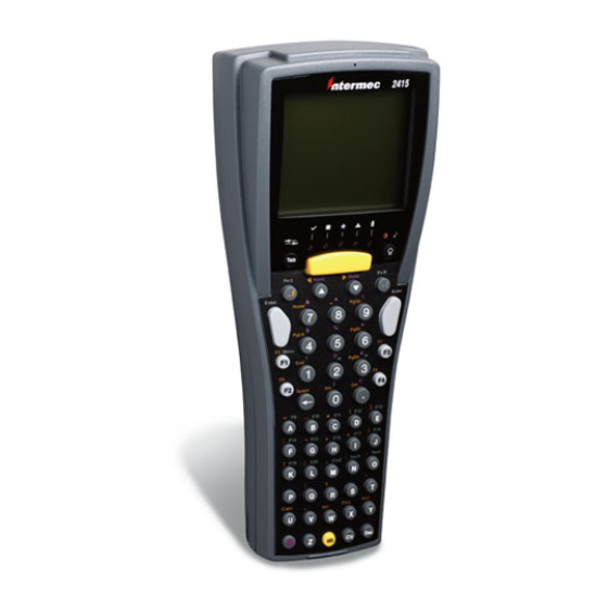
“Managing Your Terminals with Wavelink Avalanche” on page 38. Trakker Antares 241X Terminals The Trakker Antares 2410 and 2415 terminals are small, lightweight, handheld data collection terminals that are designed for a range of applications, including commercial applications such as in-store retail. -
Page 23: Trakker Antares 242X Terminals
(RF) network. Because it can communicate using RF, the 2415 provides real-time communications to a host either through the access points and the Intermec Gateway or DCS 30X, or directly through the access points. The 2415 can also run... -
Page 24: Trakker Antares 2455 Terminal
RF network. The 2435 can communicate with a host either through the access points and the Intermec Gateway or DCS 30X, or directly through the access points. The 2435 can also run client/server applications, TE 2000 terminal emulation applications and dcBrowser, which lets you run web-based applications. -
Page 25: Trakker Antares 2475 Terminal
The 2485 is a programmable data collection terminal with the additional ability to communicate in the RF network. The 2485 provides wireless communications to a host either through the access points and Intermec Gateway or DCS 30X, or directly through the access points. The 2485 has a 4-line by 40-character screen. -
Page 26: What's New In Firmware Version 8.01
The Ethernet terminal communicates with a host directly through the Ethernet network. The RF terminal also communicates with a host either through the Intermec Gateway or DCS 30X, or directly through the access points. The access point acts as a bridge between the Ethernet or wired network and the RF network. - Page 27 In a UDP Plus or WTP network, the terminal communicates through an access point using the Intermec Gateway or DCS 30X to a host on a wired network. In a TCP/IP network, the terminal communicates through the access point directly to a host on a wired network.
- Page 28 Chapter 1—Introducing the Trakker Antares 2400 Family OSI Layers Applications Presentation Session Transport Network Data Link Physical Trakker Antares Terminal Protocol Stack and the OSI Model Note: In a WTP network, the WTP core replaces the shaded layers shown. For help using WTP, see the appropriate TE 2000 user’s guide. Trakker Antares 2400 Family applications Communications API and additions Terminal Message...
- Page 29 RFC 768. Transmission Control Protocol (TCP) complies with the standard outlined in RFC 793. UDP Plus UDP Plus is an Intermec proprietary session layer protocol built on UDP. The UDP Plus session layer provides these services: •...
- Page 30 Protocols Used by the Trakker Antares Terminals (continued) Layer Application, Presentation, Session, Transport, and Network Protocol Description Wireless Transaction Protocol (WTP) is an Intermec proprietary protocol that provides these Ethernet level services: • Duplicated message removal • Guaranteed delivery • Link connection and status management •...
-
Page 31: Configuring And Managing The Terminals
This chapter describes the different methods you can use to configure the Trakker Antares • Overview of how to configure the terminals • Configuring the terminal by scanning bar code labels • Configuring the terminal through the serial port • Configuring the terminal through the network •... -
Page 32: How To Configure The Terminals
You can send configuration information to multiple terminals in your RF network using the Wavelink Avalanche client management system and the Intermec Settings (ICCU) application. For help, see “Managing Your Terminals with Wavelink Avalanche” on page 38. Trakker Antares 2400 Family System Manual... -
Page 33: About The Configurations
About the Configurations The terminal uses three configurations: current, active, and default. Having separate current and active configurations lets you control the active configuration while letting each operator make some changes to the current configuration, such as scanning a bar code to change the beep volume. - Page 34 Chapter 2—Configuring and Managing the Terminals If you want to save your changes after you boot or reset the terminal, you must save them in the terminal’s flash memory. For help, see “Saving Configuration Changes in Flash Memory” on page 29. To configure the terminal, you can scan separate bar code labels, or you can create bar code labels that contain more than one configuration command.
-
Page 35: Configuring The Terminal Through The Serial Port
Configuring the Terminal Through the Serial Port You can write a host application that configures the terminal by sending reader and configuration commands through the serial port. For a list of reader commands, see Chapter 5, “Reader Command Reference.” For a list of configuration commands, see Chapter 6, “Configuration Command Reference.”... - Page 36 Chapter 2—Configuring and Managing the Terminals commands Note: For security purposes, you cannot get the values for Security ID and WEP Key. To get the value for Symbology Identifiers, you need to use the command syntax and the value for Parameter 1. For example, to get the value for the Code 39 symbology identifier, use “Symbology Identifiers”...
-
Page 37: Configuring The Terminal Through The Network
Configuring the Terminal Through the Network You can remotely configure the RF or Ethernet terminal by using one of these methods: • Send a command from the DCS 300 (UDP Plus network only). • Send a command from an application on the host computer (UDP Plus and TCP/IP networks). -
Page 38: Sending A Command From The Dcs 300
Chapter 2—Configuring and Managing the Terminals Sending a Command From the DCS 300 You can use the DCS 300 to configure one or more terminals in your RF or Ethernet network. The DCS 300 lets you group together terminals that you want to receive the same reader and configuration commands. -
Page 39: Sending A Command From The Host
Note: You can set the Postamble or Preamble configuration command to use characters from the extended ASCII character set such as the Field Exit code for 5250 TE. For help, see the appropriate TE manual. 4 Repeat Step 3 to add another reader or configuration command, or choose OK. -
Page 40: Configuring The Terminal In A Tcp/Ip Direct Connect Network
Chapter 2—Configuring and Managing the Terminals To set up the host computer • Verify that the host computer can communicate with the DCS 300. To set up the application • Prepare and write a host application that can communicate with the DCS 300 and send transactions to and receive transactions from the terminal in this format: transaction header... - Page 41 access point or through the Ethernet network. You use the Terminal Message Format (TMF) protocol to send and receive transactions between the host application and the terminal. For more information about sending and receiving data, see “Transferring Files and Data in a TCP/IP Direct Connect Network” on page 24. Note: You can continue running an application on the terminal while configuring the terminal from the host.
- Page 42 Chapter 2—Configuring and Managing the Terminals Example 1 In the host application, you want to get the current values of two configuration commands from the terminal. Send this transaction from the host application: CG$+NABV Note: The transaction header is not shown in this example. You do not need a transaction header for a host application in a TCP/IP network.
-
Page 43: Configuring The Terminal With The Clone Application
The terminal returns this transaction to the host application. Cs$+BV4KA1 where: Configuring the Terminal With the Clone Application The clone application uses XMODEM-1K protocol to copy configuration parameters and applications from one terminal (server terminal) to another (client terminal). The server and client terminals must have the same: •... -
Page 44: Transferring Files And Data In A Tcp/Ip Direct Connect Network
Chapter 2—Configuring and Managing the Terminals To clone configuration parameters and applications 1 Make sure the server terminal’s configuration is saved in flash memory by scanning this bar code: Save Configuration in Flash Memory *.+1* *.+1* 2 Load all applications and files to clone on the server terminal’s C drive. 3 (RF terminals only) Disable the radio on both the server terminal and the client terminal. - Page 45 To use the built-in TFTP client on the RF or Ethernet terminal, the • TFTP (Trivial File Transfer Protocol) server must be running on the host. • TFTP server must be running on at least a Pentium processor or equivalent. •...
- Page 46 Chapter 2—Configuring and Managing the Terminals To use the sample utility CLIENT.CPP 1 Make sure the TFTP server is running on the host and the RF or Ethernet terminal is communicating with the host. 2 In the hosts file on the host, add the terminal IP addresses and the target name, NCM.
- Page 47 serverAddress.sin_port memcpy(&serverAddress.sin_addr, phostent->h_addr_list[0], phostent->h_length); // Bind a well known port of 6000 to the socket SOCKADDR_IN clientAddress; memset(&clientAddress, 0, sizeof(clientAddress)); clientAddress.sin_family = PF_INET; clientAddress.sin_port = htons(CLIENT_PORT); clientAddress.sin_addr.s_addr = htonl(INADDR_ANY); if(!(bind(connection, (LPSOCKADDR)&clientAddress, sizeof(clientAddress)) ==0)) ErrorMessage("bind", WSAGetLastError()); // attempt to connect to the server error = connect(connection, (const SOCKADDR *)&serverAddress, sizeof(serverAddress));...
- Page 48 Chapter 2—Configuring and Managing the Terminals Sleep(2000); // receive the converted string from the server memset(&rz, 0, sizeof(rz)); rcLen = sizeof(rz); cbRecv = recv(connection, rz, rcLen, 0); if (cbRecv < 0) Rcount++; printf("receive failed %d\n", Rcount); ErrorMessage("receive", WSAGetLastError()); bConnectionAlive = FALSE; // printf the converted string printf("response:%s\n",rz);...
-
Page 49: Saving Configuration Changes In Flash Memory
Saving Configuration Changes in Flash Memory If you configure the terminal by scanning bar code labels, using the serial port, or using the network, you may want to save the changes in flash memory by: • scanning the Save Configuration in Flash Memory reader command bar code label. -
Page 50: Restoring The Terminal's Default Configuration
Chapter 2—Configuring and Managing the Terminals 3 Choose Yes to save the configuration in flash memory. To exit without saving the configuration, choose Cancel. The System Menu appears. 4 Press d to exit the System Menu. The Main Menu appears. 5 Choose another menu from the Main Menu or press d to exit the TRAKKER Antares 2400 Menu System. -
Page 51: Upgrading The Terminal
You can also upgrade the terminal for: • TE 2000 (new releases) • Data Collection Browser™ (dcBrowser™) For pricing and availability, contact your local Intermec representative. Upgrading the Firmware When you upgrade the firmware, you remove existing applications and files on the terminal and restore the terminal’s default configuration. - Page 52 Xs represent the menu selection numbers. • Trakker Antares Firmware Upgrade Utility (TAUPGRADE.EXE). This utility is available at no charge from the Intermec web site at www.intermec.com. It allows you to upgrade the terminal firmware using a Microsoft Windows interface on a PC with Microsoft Windows 2000/NT/XP.
- Page 53 To upgrade the firmware using the Trakker Antares DOS Firmware Upgrade Utility Note: Make sure you back up your custom files and applications, such as TE 2000, dcBrowser, and ROM-DOS, so that you can reinstall them after the upgrade procedure. For help, see “Using the Serial Port to Transfer Applications and Files”...
- Page 54 Chapter 2—Configuring and Managing the Terminals 9 Choose System Menu > Upgrade Firmware. The Upgrade Firmware screen appears. Upgrade terminal firmware? Make sure the terminal is connected to a host 10 Choose OK to continue. The next screen appears. Are you sure you want to continue? Selecting YES will upgrade and replace...
- Page 55 14 Select a communications port: Type This Value A menu appears asking you to select a download speed. 15 Select a download speed: Type This Value A menu appears asking you to select which protocol stack to use. 16 Select a protocol stack: Type This Value A menu appears asking you to select the communication hardware for your terminal.
-
Page 56: Loading Double-Byte Fonts
You can also order the Thai language font as a configuration option for the Trakker Antares 2400 Family. For help, contact your local Intermec representative. Use the next table to determine which file name you need. Double-Byte Fonts... - Page 57 If you have a 241X terminal, you may also need to order a keypad overlay to use the double-byte font. For more information, contact your local Intermec representative. To load a double-byte font 1 Connect your terminal to a PC running Windows 95/98. For help, see your user’s manual.
-
Page 58: Managing Your Terminals With Wavelink Avalanche
Chapter 2—Configuring and Managing the Terminals 9 Type: FLOADER /COMn /baudrate filename.FON where: baudrate filename The font is downloaded to your terminal. 10 On your terminal, press d to exit the Loader Waiting screen, and press 1 or B to boot the terminal. Managing Your Terminals with Wavelink Avalanche You can manage Trakker Antares terminals with firmware version 8.01 or later with the Wavelink Avalanche client management system. -
Page 59: Wavelink Avalanche Files
24xxUDS.AVA 24xxULS.AVA 24xxUSS.AVA You can download these and other packages at no charge from the Intermec web site at www.intermec.com. For more information about software packages and software collections, see the Wavelink Avalanche documentation and online help. Wavelink Avalanche Files... - Page 60 Network Profiles A network profile is a collection of settings that lets you download certain network parameters to the terminal. Intermec recommends that you use network profiles to help manage your terminals. When a network profile is enabled, the Avalanche Agent downloads a file named AVA-NET.DHP to the terminal.
-
Page 61: Synchronization Properties And Selection Criteria
Chapter 2—Configuring and Managing the Terminals app_name.RCD Description and Values Current IP address I (for Intermec) ITCxxxx where xxxx is the model of the Trakker Antares terminal, such as 2415. Last two digits of the terminal model number. For example, 15 indicates the 2415. -
Page 62: Learning About Intermec Settings (Iccu)
Intermec Settings (ICCU ) is a proprietary Intermec application that allows you to easily configure multiple Trakker Antares terminals. Intermec Settings is available as part of a Wavelink Avalanche package (24XXRCD). You can download the Intermec Settings package at no charge from the Intermec web site at www.intermec.com. - Page 63 Chapter 2—Configuring and Managing the Terminals 6 Download the package to the terminals you want to configure. For more information, see the online help that ships with Intermec Settings. Trakker Antares 2400 Family System Manual...
- Page 64 Chapter 2—Configuring and Managing the Terminals Trakker Antares 2400 Family System Manual...
-
Page 65: Developing And Using Applications
This chapter explains how to create, download, and run applications on the programmable terminals and covers these topics: • About the Trakker Antares programmable terminals • Creating applications for the terminal • How to download applications • Using the serial port to transfer applications and files •... -
Page 66: About The Trakker Antares Programmable Terminals
Note: This chapter describes how to create, download, and run DOS applications. To use DOS on the Trakker Antares terminal, you must order the DOS option. For help, contact your local Intermec representative. The next table lists specifications and technical information you need to know to develop applications for the Trakker Antares terminals. - Page 67 Trakker Antares Programmable Terminal Specifications (continued) Specification Description Network UDP Plus provides host protocol connectivity through the Intermec Gateway or DCS 30X TCP/IP provides host connectivity through the RF or Ethernet network WTP provides host connectivity through the Intermec Gateway or...
-
Page 68: Creating Applications For The Terminal
6.12 or later. If you are using an earlier version of firmware, you must upgrade the firmware. For help, contact you local Intermec service representative. To create applications 1 Use the PSK or EZBuilder to develop your application. -
Page 69: Using The Psk Or Ezbuilder To Develop Applications
Developing Applications Using the PSK You can download the latest version of the PSK at no charge from the Intermec web site at www.intermec.com. This kit has a full set of programming tools to help you create applications for the terminal: •... -
Page 70: Converting Janus Applications And Irl Programs
Chapter 3—Developing and Using Applications EZBuilder contains these items: • EZBuilder software • Intermec certified 16-bit C/C++ compiler • Application Simulator • PSK libraries • FileCopy utility • Sample EZBuilder programs • EZBuilder Getting Started Guide (P/N 066450) • EZBuilder Tutorial (P/N 066449) Using EZBuilder, you enter simple commands to create menus, screens, and transactions and to define menu items, labels, and data fields. -
Page 71: Converting Irl Programs Between The 95Xx And Trakker Antares
The Trakker Antares terminals and the 95XX terminals run different types of applications. The Trakker Antares terminals can run Microsoft C/C++ applications while the 95XX terminals run IRL (Intermec Reader Language) programs. The Trakker Antares terminals support IRL by using IRL to C conversion programs. -
Page 72: Creating A Custom Logo
The conversion application (EXE2ABS.EXE) creates an executable binary file named filename.BIN. For example, if your application is named SHIPPING.EXE and the Intermec directory is on drive C, type this command on your PC: c:\intermec\im24\lib\exe2abs shipping.exe The conversion application creates the SHIPPING.BIN file. -
Page 73: How To Download Applications
How to Download Applications You can download applications and files to the programmable terminals by using any of the following methods: • Serial port • DCS 300 • Host application These methods are described in the next procedures. You can also use reader commands to transfer files. For help, see “Transmit File”... - Page 74 Chapter 3—Developing and Using Applications Use the DCS 300 to download applications and files to the terminal 1 Create your applications using the Trakker Antares PSK or EZBuilder. For help, see “Creating Applications for the Terminal” on page 48. 2 (.BIN applications) Convert each application to a binary file. •...
-
Page 75: Using The Serial Port To Transfer Applications And Files
Programmer’s Software Kit (PSK) and EZBuilder to copy files to and from the terminal. This utility is also available at no charge from the Intermec web site at www.intermec.com. • Use the VIEW246X.EXE program that comes with the firmware upgrade software to copy files to and from the terminal. You also need the FLASHLDR.BIN file that comes with the firmware upgrade... - Page 76 Chapter 3—Developing and Using Applications If you are using the FileCopy utility, you can automatically convert any .EXE file to a binary file (.BIN) before downloading the file. If you are using LOADER.EXE, you need to use EXE2ABS.EXE to convert the .EXE file to a .BIN file.
- Page 77 4 Make sure the terminal is running an application that will not be updated during the file transfer. If you are in the TRAKKER Antares 2400 Menu System, exit the menu system. You can run the APPTSK.BIN application while transferring files. For help, see “Running Applications on the Terminal”...
- Page 78 Chapter 3—Developing and Using Applications 7 Click Download to copy the file from the PC to the terminal. If you selected the Run program check box, the terminal boots, resets, and runs the application you downloaded. Otherwise, the current application continues to run on the terminal. Click Upload to copy the file from the terminal to the PC.
- Page 79 Commands (continued) Command del term_filename copyfromterm <cf> term_filename, pc_filename copytoterm <ct> pc_filename, term_filename help quit or exit To transfer applications and files to the terminal using LOADER.EXE Note: Before you can transfer applications and files, you must open the MS-DOS window and open the MS-DOS Prompt Properties dialog box. In the Memory tab, set the Initial Environment field to 4096.
-
Page 80: Using The Dcs 300 To Download Applications And Files
Chapter 3—Developing and Using Applications 5 On the terminal, access the Loader Waiting screen. Press ) ; 2 4 8 or scan this bar code label: TRAKKER Antares 2400 Menu System *..-.* *..-.* The Main Menu appears. From the Main Menu, choose System Menu > Upgrade Firmware > Choose Yes to continue. -
Page 81: Copying Applications And Files To The Dcs 300
Or, use the Receive File or Transmit File reader commands to download the applications and files to the RF or Ethernet terminal. For help, see “Transmit File” on page 116 and “Receive File” on page 105. Each step is described in the next sections. Before you start, make sure that the RF or Ethernet terminal is communicating with the DCS 300. -
Page 82: Downloading Applications And Files To The Terminal
Chapter 3—Developing and Using Applications Select the file name. Choose Select. The file name appears in the Selected Files list box. If the Selected Files list box displays any files that you do not want to restore, select the file name and choose Remove. 7 Choose Restore Files. - Page 83 4 In the Terminals and Groups list box, select a terminal or group of terminals to receive the binary applications and files. 5 Choose Edit. The Configure Device Initialization Download dialog box appears. 6 Verify that there are no files (or entries) listed in the Files and Data list box.
- Page 84 Chapter 3—Developing and Using Applications 13 Repeat Steps 7 through 12 to select another application. 14 You can also download files used by your application such as an employee list or a part number list. To download additional files, choose File in the Initialization Data box.
-
Page 85: Running Applications On The Terminal
19 Click Close to close the dialog box and return to the System Maintenance dialog box. After you download an application to the terminal, you can run the application. For help, see the next section, “Running Applications on the Terminal.” Running Applications on the Terminal After you download an application to the terminal, you are ready to run the application and use it. - Page 86 Chapter 3—Developing and Using Applications Select drive: 3 Press ; to select drive C, or press – or ª to select the letter of the drive you want to manage, and then press ;. The File Manager screen appears and lists all the files stored on the drive. C:EM9560.BIN C:ROM-DOX.IMG 50255 C:DOS.BIN...
-
Page 87: Running Diagnostics
Running Diagnostics This chapter explains how to run diagnostics on the terminal to help analyze hardware, application, and firmware problems. This chapter covers these topics: • Available diagnostics • Running diagnostics from the menu system • Defining the diagnostics screens •... -
Page 88: What Diagnostics Are Available
Tests and turns on the pixels on the screen to make sure all areas of the screen are working correctly. Lists the terminal’s hardware components that were installed at the Intermec factory, including the RF country code. Shows the hexadecimal, decimal, and scan code value for any key or key combination on the keyboard. -
Page 89: Running Diagnostics From The Menu System
nugget Diagnostics Listed by Category (continued) System Diagnostic Test Access Point Application Efficiency Code Verify Malloc Application Information Malloc Firmware Information Serial Port Test Subsystem Versions Software Diagnostic Test Application Events Clear Task Profiles Error Logger Font Test Keypad Table Task Status Running Diagnostics From the Menu System The TRAKKER Antares 2400 Menu System is a menu-driven application... - Page 90 Chapter 4—Running Diagnostics To run diagnostics from the TRAKKER Antares 2400 Menu System 1 Press ) ; 2 4 8 or scan this bar code: TRAKKER Antares 2400 Menu System *..-.* *..-.* The Main Menu appears. 2 Press † to choose the Diagnostics Menu and press ;. The Diagnostics Menu appears.
-
Page 91: Defining The Diagnostics Screens
nugget 3 Press ¥ or † to choose Software Diagnostics, Hardware Diagnostics, or System Diagnostics and press ;. One of the diagnostics menus appears. SOFTWARE DIAGNOSTICS Error Logger Application Events Task Status Clear Task Profiles Font Test Keypad Table Note: The Radio Test and Access Point diagnostics are only available for RF terminals. -
Page 92: Access Point
Chapter 4—Running Diagnostics Access Point Purpose: Use the Access Point screen to get version and address information about the access point the terminal is communicating with across the RF network. This diagnostic only applies to RF terminals. Where Available: System Diagnostics menu Sample Screen: Radio ROM Ver: V1.6EB... -
Page 93: Application Events
nugget An efficient application uses the Trakker Antares PSK (Programmer’s Software Kit) functions to wait for events to occur, and it does not poll in an infinite loop. When programmed correctly with the PSK or EZBuilder, the application uses the terminal’s battery power as efficiently as possible and does not prevent the terminal from going into Standby mode. - Page 94 Chapter 4—Running Diagnostics Note: The Backup Battery/PIC option is only available for the 242X terminal, because the 241X and 243X terminals do not have a backup battery. Sample Screen: BATTERY/PIC MONITOR Main Battery Volts 8.200V Temp: Main Charging: NO PIC Rev.:8 [Esc] Exit Main Battery/PIC Screen Definition: The Main Battery/PIC screen displays the main battery capacity, the...
-
Page 95: 2455, 2475, And 248X Terminals
Good Note: The NiCad backup battery in the 2475 and 248X is not user- serviceable. You must return the Trakker Antares 2475 or 248X terminal to Intermec to replace the backup battery. Trakker Antares 2400 Family System Manual BATTERY/PIC MONITOR... -
Page 96: Beeper Test
If you do not hear any beeps during any of these tests, you may have a problem with the beeper or internal speakers. For help, contact your local Intermec service representative. Clear Task Profiles Purpose: Clears the task profile counters so that you can begin accumulating statistics on the firmware subsystem tasks from a known point in time. -
Page 97: Code Verify
nugget Sample Screen: CLEAR TASK PROFILES Hardware Config Operating system task profiles counters have been cleared. [Esc] Exit Definition: When you select the Clear Task Profiles option, the terminal clears the %Time field on the Task Status screen. It also resets all counters that are used to calculate the Application Efficiency screen. -
Page 98: Error Logger
The fourth pattern turns off every pixel and appears as a clear square. If any of these patterns are not displayed correctly, you may have a problem with the LCD. For help, contact your local Intermec service representative. Error Logger Purpose: If you suspect that your terminal has a problem, you can use the Error Logger to help diagnose the problem. -
Page 99: Font Test
Definition: If you ordered the optional 4MB flash memory for your terminal, you can use the Trakker Antares Font Loader to download a double-byte font set to the terminal. See your local Intermec sales representative for information about ordering double-byte fonts. -
Page 100: Hardware Configuration
Font Number Hardware Configuration Purpose: If you are discussing a problem with Intermec, you can use the Hardware Configuration screen to tell the Intermec representative the exact version of hardware that was installed on the terminal at the Intermec factory. - Page 101 nugget Where Available: Software Diagnostics menu Sample Screen: KEYPAD TABLE Keypad Table [Esc] Exit Definition: This table matches the hex code on the screen with a description of the keypad table that is loaded on your terminal. Keypad Table Hex Code Description Description 0x00 Terminal Emulation, 242X...
-
Page 102: Keypad Test
Chapter 4—Running Diagnostics Keypad Test Purpose: An application programmer can use the Keypad Test screen to quickly find the hexadecimal key code value, the decimal key code value, and the scan code for any key on the keypad. You can also use the test to make sure the keypad is operating correctly. -
Page 103: Malloc Firmware Information
nugget memory fragments, and total number of allocated blocks of memory. You can use this diagnostic screen to troubleshoot a memory leak where the application is mallocing memory, but not freeing memory. Malloc Firmware Information Purpose: A programmer or application developer can use the Malloc Firmware Information screen to see how memory is allocated and used in the terminal firmware. -
Page 104: Scanner Test
If the Radio Test fails, stop using the terminal. Contact your local Intermec service representative. Attention: Si le test Radio échoue, veuillez ne plus utiliser le terminal. Contactez le représentant du service clientèle Intermec de votre région. Scanner Test Purpose: Use the Scanner Test to make sure the integrated laser scanner and scan button or the tethered laser scanner and scanner trigger are operating correctly. -
Page 105: Serial Port Test
If the laser scanner does not turn on, you may have a problem with the scan button or scanner trigger. For help with scanner problems, contact your local Intermec service representative. Serial Port Test Purpose: Use the Serial Port Test screen to test or troubleshoot serial communications between the terminal and the host computer or serial device. -
Page 106: Subsystem Versions
Intermec service representative. Subsystem Versions Purpose: If you are discussing a problem with Intermec, you can use the Subsystem Versions screen to tell the Intermec representative the exact version of firmware subsystems loaded on the terminal. Radio driver, network, or radio subsystem information only applies to RF terminals. -
Page 107: Error Numbers And Messages
nugget Definition: The %Time field measures the relative amount of time that a given software task or component is active. For example, Idle Task (ID) in the Power Management software is a component. The %Time that Idle Task is active is directly proportional to battery life. The ID (idle) address should have the largest %Time field. - Page 108 Chapter 4—Running Diagnostics Error Numbers and Messages (continued) Error Number Message 0x65 UDP+: Invalid parameter block 0x66 Network not active or not configured properly 0x67 NCB pointer is null 0x68 Data pointer is null or data length invalid 0x69 Network error 0x6A Previous application message occupies send buffer...
- Page 109 nugget Error Numbers and Messages (continued) Error Number Message 0x123 No table space available for message 0x134 Invalid file descriptor pointer 0x135 Task not suspended 0x136 Not owner of stream 0x137 Stream access error 0x138 Color requested > NUMCOLORS 0x139 Missed system time required 0x13A Mtenv table full...
- Page 110 Chapter 4—Running Diagnostics Error Numbers and Messages (continued) Error Number Message 0x202 Invalid Decodes command 0x203 Invalid Decode symbology specified 0x204 Unable to decode input scan 0x205 Missing start or stop character 0x206 Number of counts less than minimum 0x207 Invalid character found 0x208 Invalid acceleration between characters...
- Page 111 nugget Error Numbers and Messages (continued) Error Number Message 0x264 Unknown mode 0x265 Another CSP client has called SpOpen 0x266 Data pointer is NULL 0x267 Frame mode configuration error 0x268 SOM configured, but no EOM configured 0x269 SOM = EOM1 or SOM = EOM2, both invalid 0x26A SOM, EOM1, or EOM2 set to invalid...
- Page 112 Chapter 4—Running Diagnostics Error Numbers and Messages (continued) Error Number Message 0x332 INT0 detected overflow exception 0x333 Array bounds exception 0x334 Unused opcode exception 0x335 Escape opcode exception 0x336 Unused int 7E subsystem 0x337 Check for powerdown 0x340 MultiDrop or Polling Mode D protocol error 0x341 Bus error...
- Page 113 nugget Error Numbers and Messages (continued) Error Number Message 0xC0 IP format 0.x.x.x or 127.x.x.x 0xC1 Controller and device IP same 0xC2 Default router and device IP same This table lists the error numbers that are posted by the security code in the terminal and lists the message associated with each number.
- Page 114 Chapter 4—Running Diagnostics 802.1x Security Error Numbers and Messages (continued) Error Number Message 0x0540 The root certificate authority certificate was not installed or is invalid. 0x0541 No common name could be obtained from the server certificate. 0x0542 Neither of the RADIUS server names on the terminal match the name received in the server certificate.
-
Page 115: Reader Command Reference
Reader Command Reference This chapter describes the reader commands that you can use while operating the terminal. Reader commands, such as Change Configuration, allow you to perform a task on the terminal. This chapter covers these topics: • Using reader commands •... -
Page 116: Using Reader Commands
Chapter 5—Reader Command Reference Using Reader Commands A reader command causes the terminal to perform a task. Some reader commands temporarily override the configuration settings and some actually change the configuration settings. For example, you can reset the terminal to the default configuration or change the configuration. Note: Not all reader commands are supported in the Reader Command Menu on the terminal. -
Page 117: Using Accumulate Mode
Reader Commands Listed by Category Accumulate Mode Commands Backspace, 100 Clear, 101 Enter, 103 Enter Accumulate Mode, 103 Exit Accumulate Mode, 104 Operating Commands Backlight On and Off, 100 Boot Terminal, 100 Change Configuration, 101 Default Configuration, 101 TRAKKER Antares 2400 Menu System, 104 Multiple-Read Labels, 104 Reset Firmware, 111... - Page 118 Chapter 5—Reader Command Reference As you accumulate the data from bar code labels, the data is visible on the bottom line of the screen. You can edit the accumulated data with the Backspace, Clear, and Enter commands. If you are not in Accumulate mode, these commands have no effect and you will hear an error beep.
-
Page 119: Defining The Reader Commands
2 Scan the bar code labels for the data you want to enter. You can scan labels from the “Full ASCII Bar Code Chart” on page 284. Note: You can create one bar code label by combining Steps 1 and 2 above. -
Page 120: Backlight On And Off
Chapter 5—Reader Command Reference Backlight On and Off Description: Turns the backlight on to easily view the terminal screen in dimly lit environments, or turns the backlight off. If the backlight is on, it stays on for the length of time set in the Display Backlight Timeout command as long as there is no keypad or scanning activity. -
Page 121: Change Configuration
Boot Terminal Scan: *-.1* *-.1* Change Configuration Description: This command must precede any configuration command. If you enter a valid string, the terminal configuration is modified and the terminal sounds a high beep. For help with configuration commands, see Chapter 6, “Configuration Command Reference.” From Network: $+command[command]...[command n] where command is a configuration command with the value you want to... -
Page 122: Delete File
Chapter 5—Reader Command Reference If you restore the default configuration, you must set the primary network communications parameters on the RF terminal to reestablish communications with other devices in the RF network. You may also need to reset the serial port or Ethernet parameters to communicate with other devices in your wired network. -
Page 123: Enter
Enter command. For a list of decoded input devices, see your user’s manual or contact your local Intermec sales representative. From Network: Not supported... -
Page 124: Exit Accumulate Mode
Chapter 5—Reader Command Reference Exit Accumulate Mode Description: Exits Accumulate mode and transmits the current data record. If no data has been accumulated, an empty data record is entered. From Network: Not supported Keypad or Menu: Not supported Exit Accumulate Mode Scan: *-/* *-/*... -
Page 125: Receive File
If you disable multiple-read labels, the terminal processes the bar code label as a regular label and reads and decodes the space as data. A regular bar code label is executed as soon as you scan it. From Network: Not supported Keypad or Menu: Not supported Label Syntax: <Start Code><SP>data<Stop Code>... - Page 126 Chapter 5—Reader Command Reference Note: Trakker Antares filenames are up to eight characters with a three- character extension. Files you transfer from the host must use the Trakker Antares naming conventions. From Network: .%Xn,drive:filename .%Kn,drive:filename .%Yn,drive:filename .%Yn,drive: where: drive: filename is the file you want to receive and save on the terminal. Keypad or Menu: Not supported Note: To scan these bar code labels, you must configure the terminal to use Code 39 in Full ASCII mode.
-
Page 127: Receive And Convert 7-Bit Ascii Files To 8-Bit Binary Files
For help, see your user’s manual. Terminal applications are 8-bit binary files. Some network protocols like the Intermec Multi-Drop protocol in a CrossBar network use 7-bit ASCII files. When you send 8-bit binary files across a 7-bit system without converting the files, the files are not compatible and will not run on the terminal. - Page 128 Chapter 5—Reader Command Reference On the host, you use a hexadecimal conversion utility to convert the 8-bit binary file to a 7-bit ASCII hexadecimal file. Intermec has a DOS utility called HEX.EXE to convert files. The source code for HEX.EXE is also available.
-
Page 129: Receive File Through Network Communications
4 Scan this bar code label to exit Accumulate mode and receive the file. Exit Accumulate Mode *-/* *-/* Or: You can create your own bar code labels to receive files by creating a bar code in this command format: .%Hn,drive:filename Example: You want to send an application from the host in your CrossBar network to the terminal. -
Page 130: Rename File
Chapter 5—Reader Command Reference Note: To scan these bar code labels, you must configure the terminal to use Code 39 in Full ASCII mode. For help, see “Code 39” on page 146. Scan: Follow these steps: 1 Scan this bar code label: Enter Accumulate Mode / Receive File */K/O./ER/L* *+/.%R,*... -
Page 131: Reset Firmware
Keypad or Menu: From the Main Menu, choose System Menu, and then choose File Manager. Choose the drive where you want to rename files. Note: To use the bar code labels from the “Full ASCII Bar Code Chart,” you may need to configure the terminal to use Code 39 in Full ASCII mode. -
Page 132: Run Program
Chapter 5—Reader Command Reference Run Program Description: Runs the specified program or application that is stored on the terminal. Note: You cannot store and run applications from the RAM drive (E). From Network: //drive:filename where: drive: filename Keypad or Menu: From the Main Menu, choose System Menu, and then choose File Manager. -
Page 133: Save Configuration In Flash Memory
For help, see “Scanner Mode” on page 228 or “Scanner Trigger” on page 235. Note: Intermec does not recommend that you use a Scanner Trigger On or Scanner Trigger Off command with the Scanner Trigger command set to edge triggering. -
Page 134: Set Time And Date
Chapter 5—Reader Command Reference From Network: Keypad or Menu: Not supported Scan: Not supported Description: The Scanner Trigger Off command performs the same function as releasing the scanner trigger on an external scanner or the Scan button on the hand-held terminal keypad. From Network: Keypad or Menu: Not supported Scan: Not supported... -
Page 135: Status Lights Control
Status Lights Control Description: Controls the Modifier Key, Caps Lock, Good Read, and User Defined status lights on the 2455, 246X, 2475, and 248X. For a description of each light, see your user’s manual. Note: The 246X does not have a Caps Lock status light. You can also use this reader command in conjunction with the im_command function to program the User Defined status LED or status icon for the 241X and 243X terminals. -
Page 136: Transmit File
Chapter 5—Reader Command Reference Or: To turn a specific status light on or off, follow these steps: 1 Scan this bar code label: Enter Accumulate Mode / Status Lights Control *+/$%* *+/$%* 2 Scan one of these labels to set the value for digit 1: 3 Repeat Step 2 to set digits 2, 3, and 4. -
Page 137: Transmit File Through The Serial Port
Transmit File Through the Serial Port Description: Transmits a file from the terminal through the serial port and saves it on the host computer. On the host, you must receive the file using a serial communications package (for example, Windows 3.1 Terminal, Win95 HyperTerminal, Crosstalk, or ProComm) that supports one of these protocols: •... -
Page 138: Transmit And Convert 8-Bit Binary Files To 7-Bit Ascii Files
Chapter 5—Reader Command Reference Scan: Follow these steps: 1 Scan this bar code label: Enter Accumulate Mode / Transmit File */K/O/E/E* *+/%%* 2 Scan the bar code label for the communications protocol you want to use. XMODEM 3 Scan the bar code label for the terminal COM port you are using to transmit the file. - Page 139 7-bit ASCII hexadecimal file and transfer it from the terminal. On the host, you use a hexadecimal conversion utility to convert the 7-bit ASCII hexadecimal file to an 8-bit binary file. Intermec has a DOS utility called HEX.EXE to convert files. The source code for HEX.EXE is also available.
-
Page 140: Transmit File Through Network Communications
Chapter 5—Reader Command Reference 3 Scan the bar code labels for the file you want to transmit. You can scan labels from the “Full ASCII Bar Code Chart” on page 284. The label must use this format: drive:filename 4 Scan this bar code label to exit Accumulate mode and transmit the file. Exit Accumulate Mode *-/* *-/*... - Page 141 Note: To scan these bar code labels, you must configure the terminal to use Code 39 in Full ASCII mode. For help, see “Code 39” on page 146. Scan: Follow these steps: 1 Scan this bar code label: Enter Accumulate Mode / Transmit File */K/O/E/ER/L* *+/%%R,* 2 Scan the bar code labels for the file you want to transmit.
- Page 142 Chapter 5—Reader Command Reference Trakker Antares 2400 Family System Manual...
-
Page 143: Configuration Command Reference
This chapter describes all the configuration commands supported on the terminal and covers these topics: • Using configuration commands • Configuration commands listed by category • Entering variable data in a configuration command • Entering ASCII characters • Defining configuration commands Trakker Antares 2400 Family System Manual Configuration Command Reference... -
Page 144: Using Configuration Commands
Chapter 6—Configuration Command Reference Using Configuration Commands A configuration command changes the way the terminal operates. For example, you can change the Beep Volume and make the terminal beep very loud in a noisy environment. You can execute configuration commands by: •... -
Page 145: Configuration Commands Listed By Category
Configuration Commands Listed by Category This chapter lists the configuration commands in alphabetical order. Use these lists to find the configuration commands you may need to set for bar code symbologies, operations, serial network communications, or RF and Ethernet network communications. Not all configuration commands apply to all terminals. - Page 146 Chapter 6—Configuration Command Reference Operations Configuration Commands (continued) Operations Flash Memory Configuration, 186 Keypad Caps Lock, 196 Keypad Clicker, 197 Keypad Control, 197 Keypad Type, 198 Postamble, 219 Preamble, 221 RAM Drive Size, 223 Resume Execution, 226 Scan Ahead, 228 Scanner Mode, 228 Scanner Redundancy, 230 Scanner Selection, 231...
- Page 147 Serial Network Communications Configuration Commands (continued) Serial Network Communications Start of Message (SOM), 240 Stop Bits, 242 Timeout Delay, 257 RF and Ethernet Network Communications Configuration Commands RF and Ethernet Network Communications Acknowledgement Delay Lower Limit, 131 Acknowledgement Delay Upper Limit, 132 AP MAC Address, 134 Controller Connect Check Receive Timer, 163 Controller Connect Check Send Timer, 164...
-
Page 148: Entering Variable Data In A Configuration Command
Chapter 6—Configuration Command Reference 802.11b RF Network Communications Configuration Commands 802.11b RF Network AP Density, 133 Maximum Sleep Duration, 203 Medium Reservation, 204 Microwave Robustness, 205 Network Name, 211 Power Management, 220 Receive All Multicast, 224 Reservation Threshold, 225 Station Name, 242 Transmit Rate, 260 Transmit Rate Fallback, 261 WEP Encryption, 266... -
Page 149: Entering Ascii Characters
where: command For example, the command syntax for a preamble is ADdata. To change or set a preamble, scan this bar code: Enter Accumulate Mode / Change Configuration / Set Preamble *+/$+AD* *+/$+AD* The Accumulate Mode screen appears. 2 Scan a bar code label from the “Full ASCII Bar Code Chart” on page 284. - Page 150 Chapter 6—Configuration Command Reference To type a nonprintable ASCII character • Use this syntax: \xhh where hh is the two-digit hexadecimal number for the control character or the extended ASCII character. For example, to enter ETX as a preamble, type: \x03 Or, to enter Ü...
-
Page 151: Acknowledgement Delay Lower Limit
Acknowledgement Delay Lower Limit Terminals: 2415, 2425, 2435, 2455, 2475, and 2485/6. Description: When the terminal sends a message to the Intermec Gateway or DCS 30X, the terminal waits to receive a response acknowledging the message. If no response is received within the acknowledgement delay lower limit time, the terminal sends the message again at the time interval set for the lower limit. -
Page 152: Acknowledgement Delay Upper Limit
Acknowledgement Delay Upper Limit Terminals: 2415, 2425, 2435, 2455, 2475, and 2485/6. Description: When the terminal sends a message to the Intermec Gateway or DCS 30X, the terminal waits to receive a response acknowledging the message. If no response is received within the Acknowledgement Delay Lower Limit time, the terminal sends the message again at the time interval set for the lower limit. -
Page 153: Ap Density
3 Scan this bar code: Exit Accumulate Mode *-/* *-/* AP Density Terminals: 2415, 2425, 2435, 2455, 2475, and 2485/6 with 802.11b radios. Description: Controls the roaming sensitivity of the radios. You can use this parameter to virtually reduce the range of the radio. When you increase the AP density, you do not reduce the absolute range of the radio, but the roaming algorithms are modified to allow significant overlap of the radio coverage. -
Page 154: Ap Mac Address
Chapter 6—Configuration Command Reference AP MAC Address Terminals: 2415, 2425, 2435, 2455, 2475, and 2485/6. Description: Returns the MAC address of the radio that is installed in the access point that the terminal is communicating with. You can only use this read-only command in an application to return the value (MAC address) to the application. -
Page 155: Automatic Shutoff
Automatic Shutoff Terminals: All Trakker Antares terminals. Description: Defines the maximum length of time the terminal remains on when there is no activity. When you do not use the terminal for the length of time set with this command, the terminal automatically turns off as if you had pressed œ... -
Page 156: Baud Rate
Chapter 6—Configuration Command Reference 3 Scan this bar code: Exit Accumulate Mode *-/* *-/* Baud Rate Terminals: All Trakker Antares terminals. Description: Sets the baud rate for the serial port on the terminal. The baud rate must match the baud rate of the device (i.e. the host computer) that the terminal is communicating with through the serial port. - Page 157 Bar Codes: To set the default baud rate for each serial port, scan these bar codes: Default Baud Rate for COM1 *$+YA1.7* *$+YA1.7* Default Baud Rate for COM3 *$+YA3.7* *$+YA3.7* Or: To set the baud rate for one serial port: 1 Scan this bar code: Enter Accumulate Mode / Set Baud Rate *+/$+YA*...
-
Page 158: Beep Duration
Chapter 6—Configuration Command Reference Beep Duration Terminals: All Trakker Antares terminals. Description: Sets the length of the terminal’s audio signals. You can define a different duration for the high and the low beep tone. Use Beep Duration with Beep Frequency and Beep Volume to define audio signals (beeps and keyclicks) according to operator preference and work environment. -
Page 159: Beep Frequency
3 Scan the beep tone for which you are setting the beep duration: High 4 Scan this bar code: Exit Accumulate Mode *-/* *-/* Beep Frequency Terminals: 241X, 242X, 243X, 2455, 2475, and 248X. Description: Sets the frequency, or pitch, of the terminal’s audio signals. Use Beep Frequency with Beep Duration and Beep Volume to define audio signals (beeps and keyclicks) according to operator preference and work environment. -
Page 160: Beep Volume
Chapter 6—Configuration Command Reference Default Beep Frequency, 243X *$+BF1900HBF1050L* *$+BF1900HBF1050L* Default Beep Frequency, 242X, 2455, 246X, 2475, 248X *$+BF2400HBF1200L* *$+BF2400HBF1200L* Or: To set a beep frequency: 1 Scan this bar code: Enter Accumulate Mode / Set Beep Frequency *+/$+BF* *+/$+BF* 2 Scan a numeric value for data from these bar codes: 3 Scan the beep tone for which you are setting the beep frequency: High... -
Page 161: Character Set
If you set the Beep Volume command to off, you will not hear any audio signals including the keyclick. Syntax: BVdata Acceptable values for data are: Quiet Normal Loud Very loud Lower volume Raise volume Default: Very loud Menu System: Main Menu > Configuration Menu > Terminal Menu > Beeper Bar Codes: Scan one of these bar codes: Beep Volume Off *$+BV0*... - Page 162 Chapter 6—Configuration Command Reference Danish / Norwegian Swedish Italian Spanish Default: U.S. ASCII Menu System: N/A Bar Codes: Scan one of these bar code labels: U.S. ASCII Character Set *$+DX0* *$+DX0* German Character Set *$+DX2* *$+DX2* Danish Character Set *$+DX4* *$+DX4* Italian Character Set *$+DX6*...
-
Page 163: Codabar
Codabar Terminals: All Trakker Antares terminals. Description: Enables or disables decoding of Codabar symbology. Codabar is a self-checking, discrete symbology. The American Blood Commission (ABC) Codabar requires that you retain and transmit the start/stop code digits when processing a Codabar symbol. As a result, configuration CD10 is an illegal configuration. -
Page 164: Code 11
Chapter 6—Configuration Command Reference Standard, Transmit ABCD Start/Stop *$+CD21* *$+CD21* Concatenated, Discard Start/Stop *$+CD30* *$+CD30* Concatenated, Transmit DC1-DC4 Start/Stop *$+CD32* *$+CD32* Code 11 Terminals: All Trakker Antares terminals configured for non-decoded scanning. Description: Enables or disables decoding of Code 11 symbology. Code 11 is a very high density, discrete numeric bar code. -
Page 165: Code 2 Of 5
Code 2 of 5 Terminals: All Trakker Antares terminals. Description: Enables or disables decoding of Code 2 of 5 symbology. Code 2 of 5 uses the bars to encode information and the spaces to separate the individual bars. This code is discrete and self-checking. You can only enable Code 2 of 5 if the Interleaved 2 of 5 (I 2 of 5) code is disabled. -
Page 166: Code 39
Chapter 6—Configuration Command Reference 3 Scan this bar code: Exit Accumulate Mode *-/* *-/* Code 39 Terminals: All Trakker Antares terminals. Description: Enables or disables decoding of Code 39 symbology. Code 39 is discrete, variable length, and self-checking. The character set is uppercase A to Z, 0 to 9, dollar sign ($), period (.), slash (/), percent (%), space ( ), plus (+), and minus (-). - Page 167 Chapter 6—Configuration Command Reference Use Code 39 full ASCII to enter ASCII control characters or lowercase characters as data. You should also enable Code 39 full ASCII to use ASCII command characters. For example, you encode the data “sample” in Code 39 full ASCII as follows: *+S+A+M+P+L+E* *+S+A+M+P+L+E*...
- Page 168 Chapter 6—Configuration Command Reference Use this table to help configure your terminal. Code 39 ASCII Decodes Code 39 Option Non-full ASCII Full ASCII Mixed-full ASCII Syntax: CBdata Acceptable values for data must be three digits, corresponding to: Digit 1: Digit 2: Digit 3: Note: Selecting HIBC Code 39 automatically sets the configuration to non-full ASCII with the check digit transmitted.
-
Page 169: Code 93
2 Scan one of these bar codes to set the first digit: Without a Check Digit HIBC Code 39 3 Scan one of these bar codes to set the second digit: Discard Check Digit 4 Scan one of these bar codes to set the third digit: Code 39 Non-Full ASCII Code 39 Mixed-Full ASCII 5 Scan this bar code:... -
Page 170: Code 128
Chapter 6—Configuration Command Reference Bar Codes: Scan one of these bar codes: Disable Code 93 *$+CF0* *$+CF0* Code 128 Terminals: All Trakker Antares terminals. Description: Enables or disables decoding of Code 128 symbology. Code 128 is a very high density alphanumeric symbology that supports the extended ASCII character set. -
Page 171: Ucc/Ean Code 128
Enable UCC/EAN Code 128 *$+CH2* *$+CH2* Or: To configure Standard Code 128: 1 Scan this bar code: Enter Accumulate Mode / Enable Standard Code 128 *+/$+CH1* *+/$+CH1* 2 Scan one of these bar codes to disable or enable concatenation: Disable Concatenation 3 Scan this bar code: Exit Accumulate Mode *-/*... -
Page 172: Isbt Code 128
Chapter 6—Configuration Command Reference Note: A GTIN compliant EAN 128 label: 1 is 16 digits long. 2 has “01” as the first two digits of the label. With GTIN Compliance enabled, a GTIN compliant EAN 128 label will have the first two digits stripped and output 14 digits. For more information, see “GTIN Compliance”... - Page 173 Syntax: CH8data where data can be up to 10 digits corresponding to: Digit 1: Digit 2: Digits 3-4: Digits Trakker Antares 2400 Family System Manual Chapter 6—Configuration Command Reference Symbology identifier (ID) disabled. Symbology identifier enabled. Output of ]C0 indicates a single ISBT 128 bar code was read. Output of ]C4 indicates that a pair of ISBT Code 128 bar codes was read.
- Page 174 Chapter 6—Configuration Command Reference Digits Digit 10 Note: The Left Data ID and Right Data ID are used only with the restricted concatenation option. For example, the terminal will concatenate only those bar code labels with data identifiers that match the configured data identifiers.
- Page 175 2 Scan one of these bar codes to disable or enable symbology ID: Disable Symbology ID Note: Steps 3 through 9 are optional. 3 Scan one of these bar codes to disable or enable concatenation: Disable Concatenation If you disabled concatenation, go to Step 10. Otherwise, continue with Step 4.
- Page 176 Chapter 6—Configuration Command Reference National Use Bar Code (See Note) */F* *&* If you scan the Donation ID Number or National Use Bar Code, continue with Step 5. Otherwise, go to Step 6. 5 For the Donation ID Number or the National Use Bar Code, scan an alphanumeric bar code from the “Full ASCII Bar Code Chart”...
- Page 177 7 For the Donation ID Number or the National Use Bar Code, scan an alphanumeric bar code from the “Full ASCII Bar Code Chart” on page 284. • For the Donation ID Number, scan a value from 0 through 9 or uppercase A through Z.
-
Page 178: Command Processing
Chapter 6—Configuration Command Reference Command Processing Terminals: All Trakker Antares terminals. Description: Command processing allows you to disable or enable reader commands. For example, you can disable the Change Configuration command. There are two ways to enable or disable reader commands: •... - Page 179 Menu System: Main Menu > Configuration Menu > Terminal Menu > Reader Commands Note: Before using the following scanning options, you must make sure that the Enable Override option is not on. For help, see “Using the Override Options” on page 161. Bar Codes: To disable or enable all the reader commands, scan one of these bar codes: Disable All Reader Commands *$+DC0*...
- Page 180 Chapter 6—Configuration Command Reference TRAKKER Antares 2400 Menu System *..-.* *..-.* Note: Accumulate mode commands are separated into two bar codes so that the command can be accumulated rather than executed as a command. You need to scan the following bar codes in order from left to right.
-
Page 181: Using The Override Options
To quickly disable or enable the Menu System (Test and Service Mode), scan one of these bar codes: Disable Menu System *$+DC..-.0* *$+DC..-.0* Enable Menu System *$+DC..-.1* *$+DC..-.1* Using the Override Options You can disable or enable reader commands using the Command Processing configuration command or the TRAKKER Antares 2400 Menu System. - Page 182 Chapter 6—Configuration Command Reference Options for Configuration Commands Via Serial Port Option Disabled Enabled with TMF Enabled without Note: Before you can enable Configuration Commands Via Serial Port with or without TMF, you must configure the EOM command. Syntax: YTn.data where n is: COM1 serial port COM2 serial port (246X and 248X terminals only)
-
Page 183: Controller Connect Check Receive Timer
Terminals: 2415, 2425, 2435, 2455, 2475, and 2485/6. Description: During periods of inactivity on the terminal, the terminal still sends messages to the Intermec Gateway or DCS 30X to check the RF or Ethernet connection. If no message is received within the time set for the... -
Page 184: Controller Connect Check Send Timer
Terminals: 2415, 2425, 2435, 2455, 2475, and 2485/6. Description: During periods of inactivity on the terminal, the terminal still sends messages to the Intermec Gateway or DCS 30X to check the RF or Ethernet connection. The terminal sends a message at the time interval set for the Controller Connect Check Send Timer. - Page 185 Power Management Tip: Intermec strongly recommends that you use the optimum setting of 35 seconds. Syntax: NQdata Acceptable values for data are any number from 1 to 3600 seconds (60 minutes). Default: 35 seconds Menu System: Main Menu > Configuration Menu > Communications Menu > Advanced...
-
Page 186: Controller Ip Address
Terminals: 2415, 2425, 2435, 2455, 2461, 2475, 2480/1 with the Ethernet option, and 2485/6 using the UDP Plus network. Description: Defines the IP address assigned to the Intermec Gateway or DCS 30X in your network. An IP address is a unique network level address you assign to each device in a TCP/IP network. -
Page 187: Data Bits
3 Scan this bar code: . (Period) 4 Repeat Steps 2 and 3 to set the next three numbers in the controller IP address field. After you scan the last address segment, go to Step 5. Do not scan the period after the last address segment. 5 Scan this bar code: Exit Accumulate Mode *-/*... -
Page 188: Decode Security
Chapter 6—Configuration Command Reference Menu System: Main Menu > Configuration Menu > Communications Menu > Serial Port Bar Codes: Scan one of these bar codes: 7 Data Bits for COM1 *$+YI1.7* *$+YI1.7* 7 Data Bits for COM2 *$+YI2.7* *$+YI2.7* 7 Data Bits for COM3 *$+YI3.7* *$+YI3.7* 7 Data Bits for COM4... -
Page 189: Default Router
When the Intermec Gateway, DCS 30X, or host (TCP/IP network) is on a different subnetwork than the terminal, you need to set the IP address assigned to the default router. -
Page 190: Device Management
Chapter 6—Configuration Command Reference 2 Scan a numeric value from 0 to 255 to set an n field of the default router address from these bar codes. 3 Scan this bar code: . (Period) 4 Repeat Steps 2 and 3 to set the next three numbers in the default router address field. -
Page 191: Device Manager Ip Address
Default: Enabled Menu System: Main Menu > Configuration Menu > Device Management > Use Device Mgmt Bar Codes: To enable or disable Device Management: 1 Scan one of these bar codes to disable or enable Device Management: Disable Device Management *$+UD0* *$+UD0* 2 To save the changes in flash memory, scan this bar code:... - Page 192 Chapter 6—Configuration Command Reference Bar Codes: To set the default Device Manager IP Address, scan this bar code: Default Device Manager IP Address *$+UE0.0.0.0* *$+UE0.0.0.0* Or: To set the Device Manager IP Address: 1 Scan this bar code: Enter Accumulate Mode / Set Device Manager IP Address *+/$+UE* *+/$+UE* 2 Scan a numeric value from 0 to 255 to set an n field of the Device...
-
Page 193: Dhcp (Controller)
Terminals: 2415, 2425, 2435, 2455, 2461, 2475, 2480/1 with the Ethernet option, and 2485/6 using the UDP Plus network. Description: If your Intermec Gateway or DCS 30X is operating as a DHCP (Dynamic Host Configuration Protocol) client, its IP address will change each time it is turned on. -
Page 194: Dhcp (Terminal)
Chapter 6—Configuration Command Reference DHCP (Terminal) Terminals: 2415, 2425, 2435, 2455, 2461, 2475, 2480/1 with the Ethernet option, and 2485/6 using the TCP/IP or UDP Plus network. Description: When DHCP (Dynamic Host Configuration Protocol) is enabled on the terminal, the terminal receives its IP address from the DHCP server. The IP address it receives may be permanent or leased. -
Page 195: Display Backlight Timeout
3 Set the Network Activate command to enabled. 4 Exit the menu system and save all changes. Bar Codes: To use bar codes and enable the terminal to use DHCP: 1 Set the Terminal IP Address. • To enable DHCP, set the Terminal IP Address to the default value of 0.0.0.0. -
Page 196: Display Contrast
Chapter 6—Configuration Command Reference Or: To set the backlight timeout: 1 Scan this bar code: Enter Accumulate Mode / Set Backlight Timeout *+/$+DF* *+/$+DF* 2 Scan a two-digit numeric value for data from these bar codes. 3 Scan this bar code: Exit Accumulate Mode *-/* *-/*... - Page 197 Acceptable values for data are 0 to 9 where: Display Contrast Values Value Values 1 through 6 set the display contrast incrementally brighter or darker. Default: 3 (Maximum contrast) Menu System: Main Menu > Configuration Menu > Terminal Menu > Display Bar Codes: Scan one of these bar codes: 0 - Brightest or Darkest Display Contrast...
-
Page 198: Display Font Type
Chapter 6—Configuration Command Reference Display Font Type Terminals: 241X, 242X, 243X, 2455, 2475, and 248X with firmware version 6.2X and earlier. Description: Sets the number of rows and columns for a font on the terminal screen. For example, you can set a regular size font (8x8), a font with double- height characters (8x16), or a font with double-width and double-height characters (16x16). -
Page 199: Display Row Spacing
Display Row Spacing Terminals: 241X, 242X, 243X, 2455, 2475, and 2481/6 with firmware version 6.2X and earlier. Description: Sets the row spacing on the terminals. Row spacing lets you define the amount of additional space (scan lines) between the lines on the screen. The number of scan lines is two times the value you set for the row spacing. -
Page 200: Display Spacing
Chapter 6—Configuration Command Reference Display Spacing Terminals: 241X, 242X, 243X, 2455, 2475, and 2481/6. Description: Defines the font size and spacing between each row and column on the terminal screen. You specify column and row spacing between font characters in numbers of pixel columns or pixel rows to be added between the font characters. - Page 201 Digits 2-3: Any two-digit column spacing value from 00 to 15. Digits 4-5: Any two-digit row spacing value from 00 to 24. Default: 00000 (8x8 font size, no column spacing, no row spacing) Menu System: Main Menu > Configuration Menu > Terminal Menu > Display Note: When you change the display spacing, the terminal clears the screen of all data.
-
Page 202: Display Video Mode
Chapter 6—Configuration Command Reference 12x12 font size *$+DKC0000* *$+DKC0000* Or: To set the display spacing: 1 Scan this bar code: Enter Accumulate Mode / Set Display Spacing *+/$+DK* *+/$+DK* 2 Scan a five-digit numeric value for data from these bar codes. 3 Scan this bar code: Exit Accumulate Mode *-/*... -
Page 203: Domain
Syntax: DNdata Acceptable values for data are: Original Normal Inverse Nrm/Icon (243X only) Inv/Icon (243X only) Default: 0 (Original) Menu System: Main Menu > Configuration Menu > Terminal Menu > Display Bar Codes: Scan one of these bar codes: Original Display Video Mode *$+DN0* *$+DN0* Inverse Display Video Mode... -
Page 204: End Of Message (Eom)
Chapter 6—Configuration Command Reference Or: To set a value for Domain: 1 Scan this bar code: Enter Accumulate Mode / Set Domain *+/$+RW* *+/$+RW* 2 Scan a numeric value for data from these bar codes: 3 Scan this bar code: Exit Accumulate Mode *-/* *-/*... - Page 205 • LRC • Start of Message (SOM) Note: EOM cannot equal the same value as SOM, and EOM1 cannot equal the same value as EOM2. EOM cannot be set to these values: • AFF (ACK) • DLE • NEG (NAK) •...
-
Page 206: Flash Memory Configuration
Chapter 6—Configuration Command Reference 2 Scan the serial port from these bar codes: COM1 *1/N* *1.* COM3 *3/N* 3 Scan one or two bar codes for data from the “Full ASCII Bar Code Chart” on page 284. 4 Scan this bar code: Exit Accumulate Mode */M/O* *-/*... -
Page 207: Flow Control
4 If you configured flash memory to store double-byte fonts, use the Trakker Antares Font Editor to download the double-byte font set to the terminal. See your local Intermec sales representative for information about the Trakker Antares Font Editor. Flow Control Terminals: All Trakker Antares terminals. - Page 208 Chapter 6—Configuration Command Reference • CTS/RTS for DTE-DTE allows for peer connections. Each terminal’s RTS output pin is connected to the CTS input pin of the other terminal. Each terminal sets RTS whenever it is ready to receive data and waits for CTS to be set before sending data. You can configure flow control for these communications protocols: Binary, Configurable, and Polling Mode D.
-
Page 209: Gtin Compliance
2 Scan the serial port from these bar codes: COM1 *1.* *1.* COM3 *3.* *3.* 3 Scan the flow control setting from these bar codes: No Flow Control XON/XOFF Response XON/XOFF Response and Control 4 Scan this bar code: Exit Accumulate Mode *-/* *-/* 5 Repeat Steps 1 through 4 to set the flow control for another serial port. -
Page 210: Handshake
Handshake is also referred to as AFF (affirmative acknowledge) on other Intermec data collection devices. For more information, see the networking chapter in your user’s manual. Note: If you are using a decoded scanner, such as the 1551, Intermec strongly recommends that you enable Handshake. Description... - Page 211 Syntax: YJn.data where n is: COM1 serial port COM2 serial port (246X and 248X terminals only) COM3 serial port (242X terminals only) COM4 serial port (242X, 2455, and 248X terminals only) An acceptable value for data is any ASCII character. Disabled Enabled Default: No characters (Disabled)
-
Page 212: Host Ip Address
Chapter 6—Configuration Command Reference Host IP Address Terminals: 2415, 2425, 2435, 2455, 2461, 2475, 2480/1 with the Ethernet option, and 2485/6 using the TCP/IP network. Description: Defines the IP address assigned to the host computer in your RF or Ethernet network. An IP address is a unique network level address you assign to each device in a TCP/IP direct connect network. -
Page 213: Icmp (Internet Control Message Protocol)
3 Scan this bar code: . (Period) 4 Repeat Steps 2 and 3 to set the next three numbers in the host IP address field. After you scan the last address segment, go to Step 5. Do not scan the period after the last address segment. 5 Scan this bar code: Exit Accumulate Mode *-/*... - Page 214 Chapter 6—Configuration Command Reference Power Management Tip: Intermec strongly recommends that you use the optimum inactivity timeout of 5 seconds to preserve power. Syntax: RYdata Acceptable values for data are: 1-51 where data=1 sets a timeout delay of 5 seconds, data=2 sets a timeout delay of 10 seconds, and so on, up to data=51 for a timeout delay of 255 seconds.
-
Page 215: Interleaved 2 Of 5
Interleaved 2 of 5 Terminals: All Trakker Antares terminals. Description: Enables or disables decoding of Interleaved 2 of 5 (I 2 of 5) symbology. I 2 of 5 is a high-density, self-checking, continuous numeric symbology. It is mainly used in inventory distribution and the automobile industry. Enabling I 2 of 5 automatically disables Code 2 of 5. -
Page 216: Keypad Caps Lock
Chapter 6—Configuration Command Reference Or: To set Interleaved 2 of 5 to a fixed length: 1 Scan this bar code: Enter Accumulate Mode / Set Fixed Length *+/$+CA* *+/$+CA* 2 Scan a numeric value for data from these bar codes. (Use even numbers 2-32 only.) 3 Scan this bar code: Exit Accumulate Mode... -
Page 217: Keypad Clicker
Keypad Clicker Terminals: All Trakker Antares terminals. Description: Enables or disables the keypad clicker. The terminal sounds a click each time you press a key or decode a row of a two-dimensional symbology. Note: If the Beep Volume command is set to off, you will not hear any audio signals including the keyclick. -
Page 218: Keypad Type
Terminals: 241X, 242X, 243X, 2455, 2475, and 248X. Description: The keypad type is initially configured in the terminal’s firmware at the Intermec factory. If you change the keypad overlay, you need to configure the keypad type to match the new keypad overlay. - Page 219 Keypad Type: Acceptable Values for Data (continued) Value Description Terminal emulation 37-key (Function key w/large numeric) keypad, 241X International, 37-key (Function key w/large numeric) keypad, 241X U.S. English alphanumeric, 57-key keypad, 243X International alphanumeric, 57-key keypad, 243X Default: Hardware Default Menu System: Main Menu >...
- Page 220 Chapter 6—Configuration Command Reference Set Keypad Type to Portuguese Alphanumeric, 2475, 248X *$+KTC* *$+KTC* Set Keypad Type to Programmable with Backspace Key, 242X *$+KTE* *$+KTE* Set Keypad Type to IBM 5250 TE, 2455 *$+KTG* *$+KTG* Set Keypad Type to VT/ANSI TE, 2455 *$+KTI* *$+KTI* Set Keypad Type to Programmable /...
-
Page 221: Longitudinal Redundancy Check (Lrc)
Set Keypad Type to International alphanumeric, 57-key keypad, 243X *$+KTW* *$+KTW* Set Keypad Type to U.S. English function numeric, 39-key keypad, 243X *$+KTY* *$+KTY* 2 Scan this bar code to save the configuration change in flash memory: Save Configuration in Flash Memory *.+1* *.+1* 3 Scan this bar code to boot the terminal and use the new keypad type:... -
Page 222: Maximum Retries
Intermec Gateway or DCS 30X. The terminal sends connect and disconnect request messages to the Intermec Gateway or DCS 30X when you turn the terminal on and off. Tip: Intermec strongly recommends that you use the optimum setting of 7 retries. Syntax: NRdata... -
Page 223: Maximum Sleep Duration
Or: To set the maximum retries: 1 Scan this bar code: Enter Accumulate Mode / Set Maximum Retries *+/$+NR* *+/$+NR* 2 Scan a numeric value for data from these bar codes: 3 Scan this bar code: Exit Accumulate Mode *-/* *-/* Maximum Sleep Duration Terminals: 2415, 2425, 2435, 2455, 2475, and 2485/6 with 802.11b radios. -
Page 224: Medium Reservation
Chapter 6—Configuration Command Reference Or: To set the maximum sleep duration: 1 Scan this bar code: Enter Accumulate Mode / Set Maximum Sleep Duration *+/$+LI* *+/$+LI* 2 Scan a numeric value for data from these bar codes: 3 Scan this bar code: Exit Accumulate Mode *-/* *-/*... -
Page 225: Microwave Robustness
Disable Medium Reservation *$+LC0* *$+LC0* Microwave Robustness Terminals: 2415, 2425, 2435, 2455, 2475, and 2485/6 with 802.11b radios. Description: Modifies the transmit rate so it does not permanently fall back to a slower rate. You should enable this command when you are operating the terminal in a room that contains microwave ovens. -
Page 226: Modem Initialization Sequence
Chapter 6—Configuration Command Reference Characters for Modem Dial Sequence (continued) Character & <space> Default: 0 (no dial sequence) Menu System: Not supported Bar Codes: To set the default modem dial sequence, scan this bar code: Default Modem Dial Sequence *$+YD3* *$+YD3* Or: To set the modem dial sequence for COM3: Note: To set this command using the bar code labels from the “Full ASCII... - Page 227 Syntax: YM3.data where data can be up to 25 characters from this table. Characters for Modem Initialization Sequence Character & <space> Default: 0 (auto rate) Menu System: Main Menu > Configuration Menu > Communications Menu > Serial Port [COM3] Bar Codes: To set the default modem initialization sequence, scan this bar code: Default Modem Initialization Sequence *$+YM3* *$+YM3*...
-
Page 228: Msi
Chapter 6—Configuration Command Reference 3 Scan this bar code: Exit Accumulate Mode *-/* *-/* Terminals: All Trakker Antares terminals. Description: Enables or disables decoding of MSI symbology. MSI code is similar to Plessey code in that it includes a start pattern, data characters, one or two check digits, and a stop pattern. -
Page 229: Multi-Drop Address
Multi-Drop Address Terminals: 2460 and 248X with enhanced I/O board option. Description: Defines the address of the communications port when you are using Multi-Drop protocol on COM2. Each multi-drop address has unique POL and SEL characters that are automatically set when you configure the address. -
Page 230: Network Activate
RF communications. When you enable this parameter, the terminal attempts to establish communications with the Intermec Gateway, DCS 30X, or host computer. You must enable this parameter for RF or Ethernet data collection. When you disable this parameter, the network is disabled and no RF or Ethernet communications are provided. -
Page 231: Network Loopback
Messages continue to be looped back to the Intermec Gateway or DCS 30X as long as this feature is enabled. Messages originating from the terminal are still transmitted to the Intermec Gateway or DCS 30X. - Page 232 Syntax: LAdata Acceptable values for data are up to 32 ASCII characters. Default: INTERMEC Menu System: Main Menu > Configuration Menu > Communications Menu > Radio Bar Codes: To set the default network name, scan this bar code:...
-
Page 233: Network Port
23, enables VT/ANSI Telnet communications. In a UDP Plus network, set the network port on the terminal to the same value as the network port on the Intermec Gateway or DCS 30X. Syntax: NGdata Acceptable values for data are any number from 1 to 65535. -
Page 234: Parity
Chapter 6—Configuration Command Reference 3 Scan this bar code: Exit Accumulate Mode *-/* *-/* Parity Terminals: All Trakker Antares terminals. Description: Sets the parity for the serial port. The terminal uses parity for error checking in data transmissions. You can configure parity for the Binary and Configurable communications protocols. -
Page 235: Password
Or: To set no parity for each serial port, scan these bar codes: No Parity for COM1 *$+YB1.0* *$+YB1.0* No Parity for COM3 *$+YB3.0* *$+YB3 Or: To set an odd parity for each serial port, scan these bar codes: Odd Parity for COM1 *$+YB1.2* *$+YB1.2* Odd Parity for COM3... -
Page 236: Pdf417
Chapter 6—Configuration Command Reference Or: To set the password to an ASCII character string: Note: To set this command using the bar code labels from the “Full ASCII Bar Code Chart” on page 284, you must configure the terminal to use Code 39 in Full ASCII mode. -
Page 237: Plessey
Bar Codes: Scan one of these bar codes: Disable PDF417 *$+CQ0* *$+CQ0* Plessey Terminals: All Trakker Antares terminals. Description: Enables or disables decoding of Plessey symbology. Plessey code is pulse-width modulated like most other bar codes. It includes a start character, data characters, an eight-bit cyclic check digit, a termination bar, and usually a reverse start character. -
Page 238: Poll (Polling)
Chapter 6—Configuration Command Reference Poll (Polling) Terminals: All Trakker Antares terminals. Description: Solicits or requests data from a polled device. You can configure polling for the Configurable communications protocol. For more information, see the networking chapter in your user’s manual. Note: Before you can enable the Poll command, you must configure the EOM and Handshake commands. -
Page 239: Postamble
Enable Poll (Set to FS) for COM3 */D/KYR3/N%B* *$+YR3 Enable Poll (Set to FS) for COM4 */D/KYR4/N%B* *$+YR4 Note: FS is encoded as %B in a Code 39 bar code label. Postamble Terminals: All Trakker Antares terminals. Description: Sets the postamble that is appended to any data you scan with the terminal. -
Page 240: Power Management
Chapter 6—Configuration Command Reference Or: To set the postamble to an ASCII character string: Note: To set this command using the bar code labels from the “Full ASCII Bar Code Chart” on page 284, you must configure the terminal to use Code 39 in Full ASCII mode. -
Page 241: Preamble
Syntax: LHdata Acceptable values for data are: Disabled Enhanced Standard Default: Enhanced Menu System: Main Menu > Configuration Menu > Communications Menu > Radio Bar Codes: Scan one of these bar codes: Disable Power Management *$+LH0* *$+LH0* Enable Standard Power Management *$+LH2* *$+LH2* Preamble... -
Page 242: Radio Mac Address
Chapter 6—Configuration Command Reference Bar Codes: To disable the preamble, scan this bar code: Disable Preamble *$+AD* *$+AD* Or: To set the preamble to an ASCII character string: Note: To set this command using the bar code labels from the “Full ASCII Bar Code Chart”... -
Page 243: Ram Drive Size
Menu System: N/A Bar Codes: N/A RAM Drive Size Terminals: All Trakker Antares terminals. Description: Configures the size and use of the RAM drive (drive E). You can use the RAM drive to temporarily store data and files. You can also disable the RAM drive and use the additional 256K for application execution space or programmable (Malloc) memory allocations. -
Page 244: Receive All Multicast
Chapter 6—Configuration Command Reference 3 Scan this bar code: Exit Accumulate Mode *-/* *-/* 4 Scan this bar code to save the configuration change in flash memory: Save Configuration in Flash Memory *.+1* *.+1* 5 Scan this bar code to boot the terminal and use the RAM drive: Reset Firmware *-.* *-.*... -
Page 245: Reservation Threshold
Bar Codes: Scan one of these bar codes: Disable Receive All Multicast *$+LJ0* *$+LJ0* Reservation Threshold Terminals: 2415, 2425, 2435, 2455, 2475, and 2485/6 with 802.11b radios. Description: Specifies the maximum packet size that the RF terminal can send before it uses medium reservation (RTS/CTS). -
Page 246: Resume Execution
Chapter 6—Configuration Command Reference 3 Scan this bar code: Exit Accumulate Mode *-/* *-/* Resume Execution Terminals: All Trakker Antares terminals. Description: Defines the way in which the terminal resumes when you press œ to turn on the terminal. If you set this parameter to resume not allowed and you press œ... -
Page 247: Roaming Flag
COM2 for either RS-232 or RS-422/485 communications. If you are using Multi-Drop protocol, you do not need to set this parameter because the terminal automatically sets the RS-485 interface. Syntax: YK2.data Acceptable values for data are: RS-232 RS-422/485 Default: RS-232 Menu System: Main Menu >... -
Page 248: Scan Ahead
Note: Automatic mode is not supported on some tethered decoded scanners. For help, contact your local Intermec service representative. Trakker Antares 2400 Family System Manual... -
Page 249: Scanner Port (Com4)
Syntax: SBdata Acceptable values for data are: One-shot mode Automatic mode Default: One-Shot mode Menu System: Main Menu > Configuration Menu > Terminal Menu > Scanner Bar Codes: Scan one of these bar codes: Enable One-Shot Mode *$+SB0* *$+SB0* Scanner Port (COM4) Terminals: 2455. -
Page 250: Scanner Redundancy
Chapter 6—Configuration Command Reference Menu System: Main Menu > Configuration Menu > Terminal Menu > Scanner Bar Codes: Scan one of these bar codes: Enable Scanner Port *$+IX0* *$+IX0* Enable Inverted RS-232 (COM4) Port *$+IX2* *$+IX2* Scanner Redundancy Terminals: All Trakker Antares terminals. Description: Defines the number of scans (voting) of a bar code label that must decode correctly for a good read of the label. -
Page 251: Scanner Selection
Bar Codes: Scan one of these bar codes: Scanner Redundancy None *$+SR0* *$+SR0* Scanner Redundancy High *$+SR2* *$+SR2* Scanner Selection Terminals: All Trakker Antares terminals. Description: Identifies the type of scanner you have connected to the terminal. The terminal can optimize the scanning performance by using the scanner you define in this command. - Page 252 Integrated long range, high density, or high visibility scanner / scan module with long aim (241X, 242X, 243X) Integrated PDF417 scanner / scan module (241X, 242X) Serial PDF417 scanner (Intermec 1551E laser scanner) (241X, 242X, 243X) Integrated non-PDF417 linear imager (241X)
-
Page 253: Scanner Timeout
Scan button or activate a laser scanner that is connected to the terminal. Note: Scanner Timeout is not supported on PDF417 scanners, as well as, some tethered decoded scanners. For help, contact your local Intermec service representative. Trakker Antares 2400 Family System Manual Chapter 6—Configuration Command Reference... - Page 254 Chapter 6—Configuration Command Reference Syntax: SAdata Acceptable values for data are: 1-60 3-60 Note: If you are using a decoded scanner, the scanner defaults to a timeout of 3 seconds. The menu system may display the default scanner timeout value of Disabled, however, the actual timeout is 3 seconds. Do not try to set the scanner timeout to Disabled.
-
Page 255: Scanner Trigger
Edge triggering Pulse triggering Note: Earlier versions of PDF417 scanners do not support pulse triggering. For help upgrading your scanner, contact your local Intermec service representative. Syntax: SCdata Acceptable values for data are: Level triggering Edge or Pulse triggering Default: Level triggering Menu System: Main Menu >... -
Page 256: Security Identification
Chapter 6—Configuration Command Reference Security Identification (ID) Terminals: 2415, 2425, 2435, 2455, 2475, and 2485/6 with OpenAir radios. Description: Defines a password for secured transmission and receipt of data between devices in the RF network. To communicate, all access points and RF terminals in the subnetwork must have the same security ID. -
Page 257: Serial Port Protocol
Serial Port Protocol Terminals: All Trakker Antares terminals. Description: Allows you to set the protocol that the serial port uses to communicate with the connected device. Communications protocols determine exactly how data is transmitted between the terminal and the serial device. Each protocol has parameters you can set, such as baud rate and parity. - Page 258 Chapter 6—Configuration Command Reference Configurable Protocol for COM3 *$+YU3.0* *$+YU3 Or: To set the serial port protocol for one serial port: 1 Scan this bar code: Enter Accumulate Mode / Set Serial Port Protocol *+/$+YU* *+/$+YU* 2 Scan one of these bar codes to set the COM port: COM1 *1.* COM3...
-
Page 259: Server Certificate Common Name (Server Cert Cn)
Server Certificate Common Name (Server Cert CN) Terminals: 2415, 2425, 2435, 2455, 2475, and 2485/6 with an 802.11b radio with 802.1x security. Description: The Server Certificate Common Name (Server Cert CN) is the name of the certificate on the authentication server. You obtain this value from the authentication server. -
Page 260: Start Of Message (Som)
Chapter 6—Configuration Command Reference 2 Scan a value for data from the “Full ASCII Bar Code Chart” on page 284. The server certificate common name can be from 1 to 32 characters. 3 Scan this bar code: Exit Accumulate Mode *-/* *-/* Start of Message (SOM) - Page 261 Menu System: Main Menu > Configuration Menu > Communications Menu > Serial Port Bar Codes: To disable SOM for each serial port, scan these bar codes: Disable SOM for COM1 *$+YY1.* *$+YY1.* Disable SOM for COM3 *$+YY3.* *$+YY3 Or: To set SOM to an ASCII character for one serial port: Note: To set this command using the bar code labels from the “Full ASCII Bar Code Chart”...
-
Page 262: Station Name
Chapter 6—Configuration Command Reference Station Name Terminals: 2415, 2425, 2435, 2455, 2475, and 2485/6 with 802.11b radios. Description: Identifies the RF terminal to the network. For example, you may want to define station names so that you can identify RF terminals when using site survey tools. -
Page 263: Subnet Mask
DCS 30X (UDP Plus), or host (TCP/IP) and terminal are on different subnetworks. If the terminal is on a different IP subnetwork than the Intermec Gateway or DCS 30X or host, you must set the subnet mask and the default router. - Page 264 Chapter 6—Configuration Command Reference For example, if the IP address is 192.009.150.184 and the subnet mask is 255.255.255.0, the subnetwork address is 192.009.150.0. The default subnet mask 255.255.255.0 indicates that the terminal uses a standard IP network mask. Syntax: NSn.n.n.n where each n address segment is a number from 0 to 255.
-
Page 265: Suspend/Resume Control
4 Repeat Steps 2 and 3 to set the next three numbers in the subnet mask address field. After you scan the last address segment, go to Step 5. Do not scan the period after the last address segment. 5 Scan this bar code: Exit Accumulate Mode *-/* *-/*... - Page 266 Chapter 6—Configuration Command Reference Symbology Identifier Character Strings Character String AIM ISO/IEC standard User-defined ASCII character string The Symbology Identifiers command contains four parameters. To disable or enable all symbology identifiers to the ISO/IEC Standard, you need to configure the first two parameters. To enable a user-defined symbology identifier, you need to configure all four parameters.
- Page 267 Digit 4: Digits 5-8: Note: The PDF417 symbology identifier is not available on terminals that are not configured to scan PDF417 bar code labels. You also may be able to define symbology identifiers for bar code symbologies that the terminal is not configured to support.
- Page 268 Chapter 6—Configuration Command Reference Bar Codes: To set the default configuration and disable all symbology identifiers, scan this bar code: Disable All Symbology Identifiers *$+CY000* *$+CY000* Or: To set all symbology identifiers to the ISO/IEC Standard, scan this bar code: Enable ISO/IEC Standard For All Symbology Identifiers *$+CY001* *$+CY001*...
- Page 269 *09* *09* Code 2 of 5 With 2 Bar Start/Stop Codes *11* *11* UPC-A *16* *16* EAN-8 *18* *18* 3 Scan one of these bar codes: Disable Symbology ID Symbology ID Enable User-Defined Symbology ID If you enabled a user-defined symbology identifier, continue with Step 4.
-
Page 270: Tcp Maximum Retries
Chapter 6—Configuration Command Reference Example 1: You want to enable the ISO/IEC Standard symbology identifier for all bar code symbologies except Plessey. 1 Scan this bar code: Enable ISO/IEC Standard for All Symbology Identifiers *$+CY001* *$+CY001* 2 Scan this bar code: Disable ISO/IEC Standard Symbology ID for Plessey *$+CY100* *$+CY100*... -
Page 271: Tcp/Ip Maximum Transmit Timeout
TCP/IP direct connect network before it gives up. For example, a value of 20 indicates that the timeout between retries is never longer than 20 seconds. Intermec has determined that the optimum setting is 20 seconds. Syntax: NHdata... -
Page 272: Terminal Ip Address
An IP address is a unique network level address you assign to each device in a TCP/IP network. The IP address you set on the terminal must be the same as the address that is set on the Intermec Gateway, DCS 30X or host computer. - Page 273 Note: The RF or Ethernet network cannot be activated if the first address segment in the IP address is set to 127 or a number greater than 223. Default: 0.0.0.0 (DHCP enabled) Note: If you are using the TCP/IP network, the default terminal IP address enables the terminal as a DHCP client.
-
Page 274: Terminal Port
Chapter 6—Configuration Command Reference 5 Scan this bar code: Exit Accumulate Mode *-/* *-/* Terminal Port Terminals: All Trakker Antares terminals using the TCP/IP network. Description: Sets the port used to open the default TCP/IP connection. Specifying a terminal port improves host communications by ensuring that host sessions are closed down when your terminal reboots. -
Page 275: Time And Date
3 Scan this bar code: Exit Accumulate Mode *-/* *-/* Time and Date Terminals: All Trakker Antares terminals. Description: Sets the time and date on the terminal. Syntax: DBdata Acceptable values for data are 12 digits corresponding to: mm 01-12 mm 00-59 Year values (yy) from 00 to 95 are interpreted as 2000 through 2095. -
Page 276: Time In Seconds
Chapter 6—Configuration Command Reference 3 Scan this bar code: Exit Accumulate Mode *-/* *-/* Time in Seconds Terminals: All Trakker Antares terminals. Description: If you enable the Append Time command, you can enable the Time in Seconds command to append the seconds to each bar code label that is scanned into the terminal. -
Page 277: Timeout Delay
Bar Codes: To set the default time zone, scan this bar code: Set Time Zone to Pacific Standard Time *$+DZ8* *$+DZ8* Or: To set the time zone: 1 Scan this bar code: Enter Accumulate Mode / Set Time Zone *+/$+DZ* *+/$+DZ* 2 Scan a numeric value from 0 to 23 from these bar codes: 3 Scan this bar code:... - Page 278 Chapter 6—Configuration Command Reference Note: Before you can set Timeout Delay, you need to configure the EOM and Handshake commands. Syntax: YEn.data where n is: COM1 serial port COM2 serial port (246X and 248X terminals only) COM3 serial port (242X terminals only) COM4 serial port (242X, 2455, and 248X terminals only) Acceptable values for data are: 5 ms...
-
Page 279: Transmit Mode
COM3 *3.* 3 Scan the timeout delay from these bar codes: Timeout Delay 5 ms Timeout Delay 500 ms Timeout Delay 10 sec Timeout Delay 40 sec 4 Scan this bar code: Exit Accumulate Mode *-/* *-/* 5 Repeat Steps 1 through 4 to set the timeout delay for another serial port. -
Page 280: Transmit Rate
Chapter 6—Configuration Command Reference Note: Even if you set this configuration command, the radio on the RF terminal will reset the parameter as needed to maximize the broadcasting range and throughput. Syntax: RTdata Acceptable values for data are: BFSK (Binary Frequency Shift Key) QFSK (Quad Frequency Shift Key) Auto Default: BFSK... -
Page 281: Transmit Rate Fallback
Bar Codes: Scan one of these bar codes: Set Transmit Rate to Maximum Available *$+LE0* *$+LE0* Set Transmit Rate to 2 Mbps *$+LE2* *$+LE2* Set Transmit Rate to 11 Mbps *$+LE11* *$+LE11* Transmit Rate Fallback Terminals: 2415, 2425, 2435, 2455, 2475, and 2485/6 with 802.11b radios. Description: Determines if the RF terminal will try slower rates than the specified transmit rate. - Page 282 Digit 7: Note: E1022 linear imagers and later versions of integrated PDF417 and 1551 scanners do not support transmitting a number system digit for EAN-8. For help upgrading your scanner, contact your local Intermec service representative. UPC-A/EAN-13 disabled UPC-A/EAN-13 enabled...
- Page 283 Note: With GTIN (Global Trade Item Number) Compliance enabled, two zeros are padded to the beginning of UPC-A, and one zero is padded to the beginning of EAN-13 to expand the numbers to 14 digits. For more information, see “GTIN Compliance” on page 189. Default: 1111111 Digit 1: Digit 2:...
- Page 284 Chapter 6—Configuration Command Reference 4 Scan one of these bar codes to set the third digit: Disable EAN-8 5 Scan one of these bar codes to set the fourth digit: Supplementals Not Allowed Supplementals Required Five-Digit Supplementals Required 6 (Optional) Scan one of these bar codes to set the fifth digit: Discard Check Digit 7 (Optional) Scan one of these bar codes to set the sixth digit: Discard Number System Digit...
-
Page 285: User Name
User Name Terminals: 2415, 2425, 2435, 2455, 2475, and 2485/6 with an 802.11b radio and the 802.1x security option. Description: Defines the user name of the terminal for 802.1x security. If you enter a user name that is longer than 32 characters, the string is truncated, and only the first 32 characters are used. -
Page 286: Wakeup On Broadcast
Chapter 6—Configuration Command Reference Wakeup On Broadcast Terminals: 2415, 2425, 2435, 2455, 2475, and 2485/6 with OpenAir radios. Description: Determines if the RF terminal can receive broadcast messages sent from the network. If the wakeup on broadcast is enabled, the radio on the RF terminal will turn on to receive broadcast messages. -
Page 287: Wep Key
Default: Disabled Menu System: Main Menu > Configuration Menu > Communications Menu > Radio Bar Codes: Scan one of these bar codes: Disable WEP Encryption *$+LK0* *$+LK0* WEP Key Terminals: 2415, 2425, 2435, 2455, 2475, and 2485/6 with 802.11b radios. Note: The WEP Key command cannot be manually configured on terminals with the 802.1x security option. - Page 288 Chapter 6—Configuration Command Reference The following value is returned: AB<cr>AB Note: If you use nonprintable ASCII characters using the TRAKKER Antares 2400 Menu System, you must enter: \xnn where nn is the hexadecimal value of a single nonprintable character. You may not enter a character with a value of \x00 using the menu system.
-
Page 289: Wep Transmit Key
3 Scan a value for data from the “Full ASCII Bar Code Chart” on page 284. The WEP key should be five ASCII characters. 4 Scan this bar code: Exit Accumulate Mode *-/* *-/* WEP Transmit Key Terminals: 2415, 2425, 2435, 2455, 2475, and 2485/6 with 802.11b radios. Note: The WEP Transmit Key command cannot be manually configured on terminals with the 802.1x security option. - Page 290 Chapter 6—Configuration Command Reference 2 Scan a numeric value for data from these bar codes: 3 Scan this bar code: Exit Accumulate Mode *-/* *-/* Trakker Antares 2400 Family System Manual...
-
Page 291: Default Configurations And Command Syntax
This appendix lists the default configuration values and provides a configuration command reference list in alphabetical order by command syntax. Trakker Antares 2400 Family System Manual Default Configurations and Command Syntax... -
Page 292: Default Configuration
Appendix A—Default Configurations and Command Syntax Default Configuration The next tables list the terminal’s default configuration values. You can use the TRAKKER Antares 2400 Menu System to set the terminal to the default configuration. For help, see “Restoring the Terminal’s Default Configuration”... - Page 293 Operations Default Configuration (continued) Operations Command Decode Security Display Backlight Timeout Display Spacing Display Contrast Display Cursor Style Display Font Type Display Row Spacing Display Video Mode Flash Memory Configuration Keypad Caps Lock Keypad Clicker Keypad Control Keypad Type Postamble Preamble RAM Drive Size Resume Execution...
- Page 294 Appendix A—Default Configurations and Command Syntax Serial Network Default Configuration Serial Network Command Baud Rate Configuration Commands Via Serial Port Data Bits End of Message (EOM) Flow Control Handshake LRC (Longitudinal Redundancy Check) Modem Dial Sequence Modem Initialization Sequence Multi-Drop Address Parity Poll (Polling) RS-232 or RS-422/485 COM2...
- Page 295 0 (random terminal port used for TCP/IP connection) Default Value 5 seconds Allowed None BFSK No (disabled) Default Value 100 ms Enabled Disabled INTERMEC Enhanced Enabled TRAKKER 2400 Maximum available Enabled Disabled 80211 (for WEP 64 on WEP Key 1)
-
Page 296: Configuration Commands By Syntax
Appendix A—Default Configurations and Command Syntax 802.11b with 802.1x Security RF Network Default Configuration 802.11b with 802.1x Security Network Command Password Server 1 Certificate Common Name Server 2 Certificate Common Name User Name Device Management Configuration Commands Device Management Device Management Device Manager IP Address Configuration Commands by Syntax The next table lists all of the configuration commands that are available on... - Page 297 Configuration Commands Listed by Syntax (continued) Syntax CQdata CSdata CYdata DAdata DBdata DCdata DEdata DFdata DJdata DKdata DLdata DNdata DTdata DXdata DZdata EFdata ERdata EZdata FFdata FRdata IXdata KAdata KCdata KEdata KTdata LAdata LBdata LCdata LDdata LEdata LFdata LGdata LHdata LIdata LJdata LKdata...
- Page 298 Appendix A—Default Configurations and Command Syntax Configuration Commands Listed by Syntax (continued) Syntax LOdata LPdata LQdata LSdata LTdata LUdata LVdata NAdata NCdata NDdata NGdata NHdata NIdata NJdata NLdata NPdata NQdata NRdata NSdata NTdata NUdata NVdata NXdata NZdata RBdata RRdata RSdata RTdata RWdata RYdata...
- Page 299 Configuration Commands Listed by Syntax (continued) Syntax UDdata UEdata YAn.data YBn.data YCn.data YD3.data YEn.data YFn.data YIn.data YJn.data YK2.data YLn.data YM3.data YN2.data YRn.data YTn.data YUn.data YYn.data YZn.data Trakker Antares 2400 Family System Manual Appendix A—Default Configurations and Command Syntax Command Device Management Device Manager IP Address Baud Rate Parity...
- Page 300 Appendix A—Default Configurations and Command Syntax Trakker Antares 2400 Family System Manual...
-
Page 301: Full Ascii Charts
Full ASCII Charts This appendix contains the full ASCII table and the full ASCII chart of Code 39 bar code labels. Trakker Antares 2400 Family System Manual... -
Page 302: Full Ascii Table
Appendix B—Full ASCII Charts Full ASCII Table This table lists the ASCII characters and their binary, hexadecimal, and Code 39 equivalents. Full ASCII Table Binary Decimal Code 39 00000000 00000001 00000010 00000011 00000100 00000101 00000110 00000111 00001000 00001001 00001010 00001011 00001100 00001101 00001110... - Page 303 Full ASCII Table (continued) Binary Decimal Code 39 01000100 01000101 01000110 01000111 01001000 01001001 01001010 01001011 01001100 01001101 01001110 01001111 01010000 01010001 01010010 01010011 01010100 01010101 01010110 01010111 01011000 01011001 01011010 01011011 01011100 01011101 01011110 01011111 01100000 01100001 Notes for the Full ASCII Table Bit positions are 76543210.
-
Page 304: Full Ascii Bar Code Chart
Appendix B—Full ASCII Charts Full ASCII Control Characters Table Control Character Definition Null or all zeroes Start of Heading Start of Text End of Text End of Transmission Enquiry Acknowledgment Bell Backspace Horizontal Tab Line Feed Vertical Tab Form Feed Carriage Return Shift Out Shift In... -
Page 305: Symbols And Punctuation Marks
*$I* *$I* *$L* *$L* *$O* *$O* *$R* *$R* *$U* *$U* *$X* *$X* *%A* *%A* *%D* *%D* Symbols and Punctuation Marks ! (exclamation point) */A* */A* */D* */D* Trakker Antares 2400 Family System Manual Appendix B—Full ASCII Charts *$J* *$K* *$J* *$K* *$M* *$N*... -
Page 306: Numbers
Appendix B—Full ASCII Charts ' (apostrophe) */G* */G* * (asterisk) */J* */J* */O* */O* , (comma) */L* */L* *%J* *%J* *%V* *%V* ~ (tilde) *%S* *%S* *%L* *%L* *%P* *%P* Numbers */H* */I* */H* */I* - (dash) */K* */M* */K* */M* . -
Page 307: Uppercase Letters
Uppercase Letters Trakker Antares 2400 Family System Manual Appendix B—Full ASCII Charts... -
Page 308: Lowercase Letters
Appendix B—Full ASCII Charts Lowercase Letters *+A* *+A* *+D* *+D* *+G* *+G* *+J* *+J* *+M* *+M* *+P* *+P* *+S* *+S* *+V* *+V* *+Y* *+Y* *+B* *+C* *+B* *+C* *+E* *+F* *+E* *+F* *+H* *+I* *+H* *+I* *+K* *+L* *+K* *+L* *+N* *+O* *+N*... -
Page 309: International Character Support
This appendix lists some of the international characters that the terminal can display and includes the: • English and Western European font set • Japanese Katakana font set. Trakker Antares 2400 Family System Manual International Character Support... -
Page 310: Trakker Antares Terminal Font Set
Appendix C—International Character Support Trakker Antares Terminal Font Set The Trakker Antares font set that supports languages such as French, German, Italian, Portuguese, and Spanish. The terminals can also use a Japanese Katakana font set. You can develop applications that display the characters in either of the terminal font sets. - Page 311 English and Western European Font Set (continued) Character ╪ ¶ § ⎫ ⎭ ⎬ ⎦ └ Space " & ’ , (comma) - (dash) . (period) Trakker Antares 2400 Family System Manual Appendix C—International Character Support Terminal Keys Decimal Scan Code c •...
- Page 312 Appendix C—International Character Support English and Western European Font Set (continued) Character < > Terminal Keys Decimal Scan Code ) P / ( 2 Trakker Antares 2400 Family System Manual Hexadecimal...
- Page 313 English and Western European Font Set (continued) Character _ (underline) Trakker Antares 2400 Family System Manual Appendix C—International Character Support Terminal Keys Decimal Scan Code Hexadecimal...
- Page 314 Appendix C—International Character Support English and Western European Font Set (continued) Character | (solid pipe) Ç ü é â ä à å ç ê ë è ï î ì Ä Å É æ Æ ô ö ò û ù ÿ Ö...
- Page 315 English and Western European Font Set (continued) Character Ü ø £ Ø × ƒ á í ó ú ñ Ñ ¿ ® ¬ (not symbol) ½ ¼ ¡ « » ░ ▒ ▓ │ ┤ Á Â À © ╣ ║...
- Page 316 Appendix C—International Character Support English and Western European Font Set (continued) Character ¢ ¥ ┐ └ ┴ ┬ ├ ─ ┼ Ã Ã ╚ ╔ ╩ ╦ ╠ ═ ╬ ¤ δ Ð Ê Ë È € Í Î Ï ┘...
- Page 317 English and Western European Font Set (continued) Character Ó β Ô Ò õ Õ µ Þ þ Ú Û Ù ý Ý ¯ ´ ± ¾ ¶ § ÷ ¸ ° (degree) ¨ • (dot) ¹ (superscript) ³ (superscript) ² (superscript) ■...
-
Page 318: Japanese Katakana Font Set
Appendix C—International Character Support Japanese Katakana Font Set This table lists the characters that you can display on the terminal using the 8x16 font grid type or the 16x16 font grid type. To display these characters, you create an application and use the Trakker Antares PSK functions im_putchar_kana_8x16 and im_puts_kana_8x16. - Page 319 Japanese Katakana Font Set (continued) Character Decimal Hexadecimal < > Trakker Antares 2400 Family System Manual Appendix C—International Character Support Character Decimal Hexadecimal ¥ ‘...
- Page 320 Appendix C—International Character Support Japanese Katakana Font Set (continued) Character Decimal Hexadecimal ¦ (broken pipe) · < » ¼ ¾ À Á ½ ¿ — Character Decimal Hexadecimal & “ > " º Trakker Antares 2400 Family System Manual...
-
Page 321: Using Default And Optional Applications
This appendix describes how to determine which default applications you may have loaded on your terminal. It also describes how to use the APPTSK.BIN and EM9560.BIN applications and describes how to use the optional DOS applications. This appendix covers these topics: •... -
Page 322: About The Applications Shipped On The Terminal
Appendix D—Using Default and Optional Applications About the Applications Shipped on the Terminal Unless you have the 802.1x security option, the Trakker Antares terminals ship with these two applications: • APPTSK.BIN • EM9560.BIN Both applications are stored on drive C. In addition to these two applications, your terminal may have a TE 2000™... -
Page 323: Dcbrowser Client
nugget 4 Type C R 5 2 4 0 1 and press ;. 5 Select Protocol Opts > Data Stream, and then select the appropriate TE 2000 configuration. 6 Save your changes by selecting Exit Menus from the TE 2000 main menu. -
Page 324: Defining The Emulation Features Of Em9560.Bin
EM9560.BIN This application emulates a subset of the functionality available on the Intermec 95XX terminals, such as the 9512 and 9560. You can use EM9560.BIN to scan, enter, transmit, and display data. APPTSK.BIN and EM9560.BIN include these features: •... -
Page 325: Using Display Control Codes
nugget • When Code 128 is configured for Standard Code 128 symbology and you scan a UCC/EAN label, the terminal will discard the Function 1 characters. Although this does not meet the industry standard for Code 128, it does emulate the 95XX, which was manufactured before the current standard was established. -
Page 326: Using Display Modes
Appendix D—Using Default and Optional Applications Display Control Codes Command Backspace Cursor Position Erase Display Home Next Line Restore Cursor Position Save Cursor Position Using Display Modes With the EM9560.BIN application, you can use Buffered display mode and Transparent display mode. In Buffered mode, new data is placed on a new line keeping blocks of data separated. -
Page 327: Using Accumulate Mode
nugget Syntax: DMdata Acceptable values for data are: Buffered display mode Transparent display mode Default: Transparent display mode Bar Codes: Scan one of these bar codes: Buffered Display Mode *$+DM0* *$+DM0* Other: To provide compatibility with the 95XX, you can also use this syntax: ODdata where data is a 0 or 1. -
Page 328: Setting Preambles And Postambles
Appendix D—Using Default and Optional Applications 4 Scan this bar code: Exit Accumulate Mode */M/O* *-/* Setting Preambles and Postambles With the EM9560.BIN application, you can set Preamble A, Preamble B, and Postamble C on the terminal and make it compatible with the 95XXs. The preambles are prepended and the postamble is appended to the data that is transmitted through all the serial ports. -
Page 329: Full Ascii Mode For Code 39
nugget Or: To set the preamble or postamble using the +., ++, or +% reader commands: 1 Scan one of these bar code labels: Enter Accumulate Mode / Set Preamble A *+/+.* *+/+.* Enter Accumulate Mode / Set Preamble B *+/++* *+/++* Enter Accumulate Mode / Set Postamble C... -
Page 330: Using Message Length Headers
Appendix D—Using Default and Optional Applications Bar Codes: Full ASCII *+$* *+$* Command: Exit Full ASCII Mode reader command Description: Exits Code 39 Full ASCII mode and puts the terminal in Code 39 Non- Full ASCII mode (one-character encoding scheme). Syntax: -$ Bar Codes: Exit Full ASCII... -
Page 331: Unsupported 95Xx Features
nugget Unsupported 95XX Features These 95XX features are not supported by the EM9560.BIN application on the terminal. • Capacity reader command (%$). • Command Override reader (data entry) command (DLE). • Download Program command from the 9154 or 9161 controller. Use the Transmit File reader command. - Page 332 Appendix D—Using Default and Optional Applications Run EM9560.BIN */O/OC/ZEM9560/NBIN* *//C:EM9560.BIN* The terminal boots, resets all firmware, and runs the application. The initial screen for the application appears. You see one of these screens: APPTSK.BIN Screen 1998/01/00 If you are using a large font size or small column width, only the hours and minutes will be displayed on the APPTSK.BIN initial screen.
-
Page 333: Using Dos On The Terminal
nugget Example 3 Connect the TD2400 communications dock to a serial port on the 2485. Use a 2420 to collect data. Use the TD2400 communications dock to upload data from the 2420 to the 2485. Data is transmitted to the 2485 and out the Ethernet or RF port to the connected network devices. - Page 334 Appendix D—Using Default and Optional Applications DOS Drives Drive Drive A Drive B Drive C The following DOS files are installed originally on drive C. File DOS.BIN ROM-DOS.IMG DRIVEB.IMG Note: If you do not want to use DOS on the Trakker Antares terminal, you can save space by deleting DOS.BIN, ROM-DOS.IMG, and DRIVEB.IMG from drive C.
-
Page 335: Starting Dos On The Terminal
nugget DOS .EXE applications are customer defined. You have 380K total RAM that you can use for DOS .EXE application execution space. You can also configure a DOS RAM drive. If the RAM drive is configured, your application execution space is reduced by the amount of the RAM drive. The remaining RAM is the Malloc/free memory pool. -
Page 336: Running Dos Applications And Using Rom-Dos Commands
Appendix D—Using Default and Optional Applications Press ; to select drive C. The File Manager screen appears listing all the files stored on drive C. Note: Drive C may contain additional applications, such as custom applications or terminal emulation applications. Choose C:DOS.BIN and press ;. -
Page 337: Using Rom-Dos Commands
nugget DOS applications and Trakker Antares applications are mutually exclusive. You can either run a DOS .EXE application or you can run a native Trakker Antares .BIN application. Note: You cannot run a DOS .EXE application from the TRAKKER Antares 2400 Menu System. To run a DOS application 1 If necessary, change to the drive where the application is stored. - Page 338 DOS commands, see a DOS manual. Note: You must use the ROM-DOS commands that are provided on the terminal. The ROM-DOS commands are also available from the Intermec web site at www.intermec.com. DOS commands or ROM-DOS commands copied from another computer will not run on a Trakker Antares terminal.
- Page 339 nugget ROM-DOS Commands in Alphabetical Order (continued) ROM-DOS Command DISKCOMP DUMP ECHO ERASE EXIT FIND GOTO LOADHIGH MIRROR MODE MORE MOVE PAUSE PROMPT REMDISK Trakker Antares 2400 Family System Manual Appendix D—Using Default and Optional Applications External ROM-DOS Command on Supported? Default Drive B Limited...
-
Page 340: Using The Pm.com Command
Appendix D—Using Default and Optional Applications ROM-DOS Commands in Alphabetical Order (continued) ROM-DOS Command REMSERVER SHIFT SORT Standard console redirection commands SUBST TIME TREE TYPE VDISK VERSION.SYS XCOPY Using the PM.COM Command PM.COM is a Trakker Antares command that enables or disables the power management scheme used by the BIOS get keyboard key function and the BIOS check keyboard key function. -
Page 341: Stopping Dos And Running A .Bin Application
B. • creating a DOS application or TSR for drive C. Intermec recommends that you create all the files on your PC, and then download the files to your terminal. The next section explains the DOS software tools that you need to customize drive A and B. -
Page 342: Customizing Drive A
Appendix D—Using Default and Optional Applications PROMERGE.EXE, and ROMDISK.EXE are support files that are required to use MAKE_A.BAT, MAKE_B.BAT, and PUT_A.BAT. Customizing Drive A Drive A is a 64K block of flash memory that is a read-only DOS drive. You can configure drive A, but you cannot write to it when you run an application. -
Page 343: Changing Dos Files On Drive A
You can download the DOS software tools and a copy of the original drive A files from the Intermec web site. For help, see “Trakker Antares DOS Software Tools” on page 321. 2 In the DOSTOOLS directory, create a subdirectory named DRIVEA that contains all the drive A files. -
Page 344: Customizing Drive B
Appendix D—Using Default and Optional Applications 4 From the DOSTOOLS directory, type this command: MAKE_A.BAT The batch file creates the image file named DRIVEA.BIN that contains all the files in the subdirectory DRIVEA. 5 Connect the PC to the terminal through a serial connection. 6 On the terminal, press ) ;... -
Page 345: Configuring A Dos Ram Drive
Intermec, because some of these commands have been modified specifically for the Trakker Antares terminal. You can download the ROM-DOS commands from the Intermec web site. For help, see “Trakker Antares DOS Software Tools” on page 321. To change the contents of drive B 1 On the PC, create a new directory or folder named DOSTOOLS and copy the DOS tool MAKE_B.BAT into this directory. - Page 346 Appendix D—Using Default and Optional Applications To configure a DOS RAM drive 1 On your PC, edit or create the CONFIG.SYS file. 2 Remove “rem” from the start of this line: rem device=b:\vdisk.sys 3 Add or set parameters for the DOS RAM drive using this syntax: device=vdisk [size [secs[dirs]]][/E] where: vdisk...
-
Page 347: Limitations Of Rom-Dos
nugget Limitations of ROM-DOS The Trakker Antares terminal supports a limited set of DOS. Here are the limitations: • Applications cannot interact directly with hardware nor memory locations such as timer ticks. • Ctrl-Alt-Del is not supported. Use the Reset Firmware command or boot the terminal. -
Page 348: Dos Architecture On The Terminal
Appendix D—Using Default and Optional Applications ROM-DOS BIOS Interfaces (continued) BIOS Interface INT 16H – Keypad Functions INT 16H functions 00H, 01H, 10H, 11H, 12H INT 17 – Time Functions INT 1AH functions 00H, 01H, 02H, 03H, 04H, 05H INT 1AH functions 06H, DOS Architecture on the Terminal The following diagram shows the Trakker Antares DOS architecture compared to the JANUS... -
Page 349: Index
Index Trakker Antares 2400 Family System Manual... - Page 350 Index Symbols and Numbers œ key configuring, 226 enabling or disabling, 245 2400 Family described, 2 See also terminal. 8.01, firmware, overview of features, 6 802.11b network communications AP Density, configuring, 133 configuration commands, list of, 275 Maximum Sleep Duration, configuring, 203 Medium Reservation, configuring, 204 Network Name, configuring, 212 Power Management, configuring, 220...
- Page 351 Backlight On and Off reader command, 100 backlight, configuring the timeout, 175 Backspace reader command, 100 bar code labels ASCII chart, 284 to 88 decode security, configuring, 168 Multiple-Read labels, 104 regular labels, 104 scanning accumulating data, 97 configuring the terminal, 13 using to configure the terminal, 124 using to execute reader commands, 96 bar code symbologies...
- Page 352 Index configuration commands (continued) Code 39, 146 Code 93, 149 Command Processing, 158 Configuration Commands Via Serial Port, 161 Controller Connect Check Receive Timer, 163 Controller Connect Check Send Timer, 164 Controller IP Address, 166 Data Bits, 167 Decode Security, 168 Default Router, 169 Device Management, 170 Device Manager IP Address, 171...
- Page 353 23 Default Configuration Command, using, 101 default configuration, restoring, 30 flash memory, 186 host application, using, 15 Intermec Settings, using, 42 overview of methods, 12 remotely example, 16, 22 from DCS 300, 18 from host, 19 to 23...
- Page 354 Index DOS (continued) drives customizing, 321 described, 314 drive A, modifying, 322 drive B, modifying, 324 files, described, 314 software tools, defined, 321 starting, 315 stopping, 321 DOS RAM drive configuring, 325 described, 314 differences from standard drive E, 314 double-byte fonts configuring flash memory, 186 determining which font is loaded, 79...
- Page 355 Interactive Reader Language, See IRL Interleaved 2 of 5 command described, 195 disabled with Code 2 of 5, 145 Intermec Settings, using to configure the terminal, 42 international languages, table of characters, 290 to 97, 298 to 300 Internet Control Message Protocol, See ICMP...
- Page 356 Index Multi-Drop address, configuring, 209 protocol configuring, 237 receiving and converting files, 107 transmitting and converting files, 118 Multiple-Read Labels reader command, 104 Network Activate command, 210 network communications controller IP address, configuring, 166 default router, configuring, 169 DHCP (Controller), configuring, 173 DHCP (Terminal), configuring, 174 Ethernet network, activating, 210 host IP address, configuring, 192...
- Page 357 reader commands Abort Program, 99 accumulate mode commands, list of, 97 Accumulate mode, using, 97 Backlight On and Off, 100 Backspace, 100 Boot Terminal, 100 Change Configuration, 101 Clear, 101 Default Configuration, 101 Delete File, 102 enabling or disabling, 158 Enter Accumulate Mode, 103 Exit Accumulate Mode, 104 file management commands, list of, 97...
- Page 358 DCS 300, 18 from host, 19 to 23 from host computer, 19 overview of methods, 12 serial port, using, 15 using Intermec Settings, 42 using Wavelink Avalanche, 38 default configuration, list of, 272 Trakker Antares 2400 Family System Manual...
- Page 359 terminal (continued) diagnostics, using, 68 DOS architecture, 328 double-byte fonts, loading, 36 firmware upgrading, 31, 41 version 8.01, overview of features, 6 protocol stack, illustrated, 8 Terminal Download Configuration dialog box, 62 terminal emulation choosing the TE 2000 configuration, 302 See also the TE 2000 5250 Terminal Emulation Programmer’s Guide, the TE 2000 3270 Terminal Emulation Programmer’s Guide, or...
- Page 360 Index Wavelink Avalanche (continued) reader command files defined, 40 guidelines for creating, 41 selection criteria, described, 41 software collection, defined, 39 software package, defined, 39 synchronization properties, described, 41 Trakker Antares protocol packages, defined, 39 upgrade files, defined, 41 WEP Encryption command, 266 WEP Keys command, 267 WEP Transmit Key command, 269 Western European languages, See European languages...
- Page 362 Corporate Headquarters 6001 36th Avenue West Everett, Washington 98203 U.S.A. tel 425.348.2600 fax 425.355.9551 www.intermec.com Trakker Antares 2400 Family System Manual *071389-006* P/N 071389-006...
- Page 363 Addendum ® Trakker Antares Firmware Version 8.02...
- Page 364 The information contained herein is proprietary and is provided solely for the purpose of allowing customers to operate and service Intermec-manufactured equipment and is not to be released, reproduced, or used for any other purpose without written permission of Intermec.
- Page 365 Contents How to Use This Addendum... 5 File System Enhancements... 6 Flash Memory Configuration Command... 6 Double-Byte Font Support ... 7 Font Test Diagnostic Update... 8 Wavelink Avalanche Update ... 9 802.1x LEAP Security Change... 9 Time Zone Configuration Command... 10 Keypad Type Configuration Command...
- Page 366 Contents Trakker Antares Firmware Version 8.02 Addendum...
-
Page 367: How To Use This Addendum
If you have an earlier version of firmware, you can download version 8.02 at no charge from the Intermec web site at www.intermec.com. If you are using firmware version 8.01 or earlier and you are not going to upgrade to firmware version 8.02, use your Trakker Antares user’s manual and system... -
Page 368: File System Enhancements
File System Enhancements Previously, on Trakker Antares terminals you could use the optional 2MB extended flash memory: • for 802.1x TTLS security. • to store double-byte fonts. • as a storage drive (drive D) for files. With firmware version 8.02, these options are no longer mutually exclusive. -
Page 369: Double-Byte Font Support
To use double-byte fonts with 802.1x TTLS security, you need to order one of the following compatible double-byte fonts. For help ordering fonts, contact your local Intermec representative. Trakker Antares Firmware Version 8.02 Addendum Configure Flash Memory... -
Page 370: Font Test Diagnostic Update
Double-Byte Fonts Compatible With 802.1x TTLS Security Language Simplified Chinese, VT Simplified Chinese, 5250 Big 5 Chinese, VT Big 5 Chinese, 5250 Japanese EUC (unix), VT Japanese, 5250 Korean, VT Korean, 5250 Note: If you are using the VT Simplified Chinese, VT Big 5 Chinese, or VT Japanese fonts, there is not enough flash memory to configure a drive D. -
Page 371: Wavelink Avalanche Update
Wavelink Avalanche Update The Wavelink Avalanche configuration package has been renamed. The name has been changed from 24xxRCD.AVA to 24xxCFG.AVA. 802.1x LEAP Security Change 802.1x LEAP security now requires Network EAP instead of Open as an authentication type. To enable 802.1x LEAP security on the terminal 1 Make sure that: •... -
Page 372: Time Zone Configuration Command
If you just want to make sure that your terminal can be authenticated, you can use the default values of “anonymous” and “anonymous.” However, Intermec recommends that you set your permanent user name and password to unique values. For help, see Chapter 6, “Configuration Command Reference,”... -
Page 373: Keypad Type Configuration Command
Keypad Type Configuration Command Terminals: 243X Description: The keypad type is initially configured in the terminal’s firmware at the Intermec factory. If you change the keypad overlay, you need to configure the keypad type to match the new keypad overlay. Syntax: KTdata where acceptable values for data are listed in the next table. - Page 374 Corporate Headquarters 6001 36th Avenue West Everett, Washington 98203 U.S.A. tel 425.348.2600 fax 425.355.9551 www.intermec.com Trakker Antares Firmware Version 8.02 Addendum *941-000-001* P/N 941-000-001...
Need help?
Do you have a question about the Trakker Antares 2410 and is the answer not in the manual?
Questions and answers