
Related Manuals for MacDon M150 2008


Summary of Contents for MacDon M150 2008
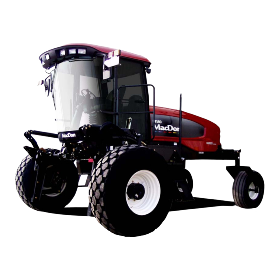
- Page 1 M150 & M200 Self-Propelled Windrower OPERATOR’S MANUAL MODEL YEAR – JUNE 2008 Part #169017 $25...
- Page 2 This Manual contains instructions for “SAFETY”, “OPERATION”, and “MAINTENANCE/SERVICE” for your new MacDon Model M150 and M200 Self-Propelled Windrower. CALIFORNIA Proposition 65 Warning Diesel engine exhaust and some of its constituents are known to the State of California to cause cancer, birth defects, and other reproductive harm.
-
Page 3: Introduction
1 INTRODUCTION This manual contains information on the MacDon Model M150 & M200 Self-Propelled Windrowers that are designed to cut and lay in windrows, a wide variety of grain, hay and specialty crops. Windrowing allows starting the harvest earlier, protects the crop from wind damage, and gives you more flexibility in scheduling combine time. -
Page 4: Table Of Contents
TABLE OF CONTENTS Section/Title Page INTRODUCTION ............................ 1 SAFETY ..............................6 SAFETY ALERT SYMBOL ......................6 SIGNAL WORDS ........................... 6 SAFETY SIGNS ..........................6 2.3.1 Safety Sign Installation ..........................6 2.3.2 Safety Sign Locations ..........................6 GENERAL SAFETY ........................11 ACRONYMS AND ABBREVIATIONS .................... - Page 5 TABLE OF CONTENTS 6.2.1 Engine Functions ............................ 48 6.2.2 Windrower Tractor Operating Symbols ....................48 6.2.3 Header Functions ............................ 49 WINDROWER TRACTOR OPERATION ..................50 6.3.1 Operational Safety ..........................50 6.3.2 Break-In Period ............................50 6.3.3 Pre-Season Check ..........................52 6.3.4 Daily Check .............................
- Page 6 TABLE OF CONTENTS 7.8.6 HVAC System ............................120 CUMMINS ENGINE (M150) ...................... 123 7.9.1 General Engine Inspection ........................123 7.9.2 Manually Turning Engine ........................123 7.9.3 Oil Level ............................... 124 7.9.4 Changing Oil and Oil Filter ........................125 7.9.5 Air Intake System ..........................127 7.9.6 Fuel System ............................
- Page 7 TABLE OF CONTENTS REEL DRIVE & LIFT PLUMBING ....................210 TRACTOR HYDRAULIC COMPLETION FOR DRAPER HEADER REEL FORE/AFT .... 210 DOUBLE WINDROW ATTACHMENT ..................210 REVERSER VALVE AND PLUMBING ..................210 BOOSTER SPRING KIT ......................210 INTERNAL BOOSTER SPRING KIT ..................210 LIGHT HEADER FLOTATION KIT ....................
-
Page 8: Safety
SAFETY 2 SAFETY WARNING Indicates a potentially hazardous situation 2.1 SAFETY ALERT SYMBOL that, if not avoided, could result in death or serious injury. It is also used to alert against unsafe practices. CAUTION Indicates a potentially hazardous situation that, if not avoided, may result in minor or moderate injury. - Page 9 SAFETY Safety Sign Locations (continued) IN CAB #32744 BELOW DOOR HANDLE #32744 FRONT OF PLATFORM #134070 BEHIND DOOR #109843 LIFT LINKAGES #163561 Form 169017 Issue – June 2008...
- Page 10 SAFETY Safety Sign Locations (continued) IN CAB #109868 BEL0W DOOR HANDLE #32744 IN CAB #109844 FRONT OF PLATFORM #110989 BEHIND DOOR #109843 Form # 169017 Issue – June 2008...
- Page 11 SAFETY Safety Sign Locations (continued) ON FAN SHROUD #134068 ON FRAME #42130 ON FRAME #110986 Form 169017 Issue – June 2008...
- Page 12 SAFETY Safety Sign Locations (continued) ON DRINK COOLER #109866 ON FRAME #110986 INSIDE FRAME #32743 ON LIFT LINKAGE #163562 Form # 169017 Issue – June 2008...
-
Page 13: General Safety
SAFETY 2.4 GENERAL SAFETY CAUTION following general farm safety precautions that should be part of your operating procedure types machinery. • Provide a first-aid kit for use in case of emergencies. • Protect yourself. • Keep a fire extinguisher on the machine. Be sure the extinguisher is properly maintained and be familiar with its proper use. - Page 14 SAFETY • Keep all shields in place. Never alter or remove safety equipment. Make sure driveline guards rotate independently of the shaft and can telescope freely. • Use only service and repair parts made approved equipment manufacturer. Substituted parts may not meet strength, design,...
-
Page 15: Acronyms And Abbreviations
SPECIFICATIONS 3 ACRONYMS AND ABBREVIATIONS 3.2 ENGLISH/METRIC EQUIVALENTS 3.1 DEFINITIONS ENGLISH FACTOR SI UNITS (METRIC) TERM DEFINITION acres x 0.4047 = hectares (ha) American Petroleum Institute ft/min x 0.3048 = meters/min (m/min) American Society Of Testing And ft/s x 0.3048 = meters/sec (m/s) ASTM Materials... -
Page 16: Specifications
SPECIFICATIONS 4 SPECIFICATIONS 4.1 TRACTOR DIMENSIONS 133 in. (3378 mm) 45.7 in. (1160 TREAD WHEEL BASE HUBS CAB FORWARD TIRES TREAD WHEEL BASE CASTERS ENGINE FORWARD WHEEL BASE WHEEL TREAD HUBS CASTERS TIRES SHIPPING Inch (mm) POSITION Inch (mm) Inch (mm) Inch (mm) Inch (mm) Inch (mm) -
Page 17: Specifications
SPECIFICATIONS 4.2 SPECIFICATIONS M150 M200 ENGINE Type Cummins QSB-130 4 Cyl. Turbo Cat C6.6 6 Cyl. Turbo Displacement 275 cu.in. (4.5 L) 403 cu.in. (6.6 L) Rated 130 hp (97 kW) @ 2200 rpm 213 hp (159 kW) @ 2200 rpm Power Peak 140 hp (104 kW) @ 2000 rpm... - Page 18 SPECIFICATIONS M150 M200 HEADER LIFT/TILT Hydraulic Type Displacement 0.84 cu.in. (13.8 cc) Gear Pumps (2) Flow 11.5 U.S. gpm (46.5 L/min) System Pressure (Relief/Max) 2500 psi (17.24 MPa) HEADER FLOTATION Manual, External, Draw-Bolt With Springs (1 per side) Primary Adjustment Hydraulic, In-Cab Switch Fine Adjustment Hydraulic, 3 Programmable Settings For All Headers (Deck Shift...
-
Page 19: Operator's Station
OPERATOR’S STATION 5 OPERATOR’S STATION The operator’s station is designed for operating the windrower tractor in a cab forward mode (working mode), or in an engine forward mode (transport mode). The operator station, which includes the seat, console, and steering column, pivots 180°... -
Page 20: Operator Presence
OPERATOR’S STATION 5.2 OPERATOR PRESENCE 5.2.2 Engine and Transmission • The engine will not be allowed to start when The Operator Presence System is a safety the header drive switch is engaged. feature that is designed to deactivate or alarm •... -
Page 21: Training Seat
OPERATOR’S STATION a. To fasten seat belt, pull belt completely across 5.4 TRAINING SEAT your body. Push the metal eye into the buckle until it locks. Adjust the position of the belt as low on your body as possible. SEAT BELT RELEASE A wall mounted fold-up training seat complete with seat belt is provided for use as described... -
Page 22: Lights
OPERATOR’S STATION 5.7 LIGHTS 5.7.1 Cab Forward Lighting The field and transport light switches are located on a panel in the cab headliner. Refer to illustrations on following pages for location of lights. LIGHTS SWITCH Controls Field and Transport Lights FIELD ROAD HI/LO LIGHTS... -
Page 23: Engine Forward Lighting
OPERATOR’S STATION 5.8 WINDSHIELD WIPERS 5.7.2 Engine Forward Lighting FRONT WIPER SWITCH Controls Front Windshield Wiper ON/OFF REAR WIPER SWITCH Controls Rear Windshield Wiper TURN SIGNALS/HAZARDS - AMBER ON/OFF The windshield wiper controls are located in the cab headliner. The illustration above right designates the controls as in the cab forward mode. -
Page 24: Cab Temperature
OPERATOR’S STATION 5.10.2 Air Distribution 5.10 CAB TEMPERATURE The cab environment is controlled by a climate- control system that provides clean air- OPEN conditioned or heated air for the operator. The heater/evaporator/blower assembly is located CLOSE under the cab floorboard and is accessible from beneath the windrower tractor. -
Page 25: A/C Compressor Protection
OPERATOR’S STATION 5.10.4 A/C Compressor Protection 5.12 OPERATOR AMENITIES The compressor is protected from excessively low and high pressures by two switches that UTILITY TRAY CIGARETTE UNDER ARMREST shut down the compressor to prevent damage to LIGHTER the system. • The LOW pressure switch opens when the pressure falls to 5.1-10.9 psi (35-75 kPa) and shuts down the compressor. -
Page 26: Radios
OPERATOR’S STATION 5.13 RADIOS 5.13.1 AM/FM Radio 11 GA. OR 3.0 mm CQHRS A radio is available as optional equipment from IMPORTANT your dealer and a space (A) is provided in the Antenna base can only be installed on the cab headliner to accommodate the installation. -
Page 27: Engine Controls/Gauges
OPERATOR’S STATION 5.14 ENGINE CONTROLS/GAUGES All engine controls and gauges are conveniently located on the operator’s console. Refer to the following illustration for the location and a description of each. IGNITION SWITCH ACC – Fully Counter-Clockwise OFF – All Electrical Systems Off RUN –... -
Page 28: Windrower Controls
OPERATOR’S STATION 5.15 WINDROWER CONTROLS GROUND SPEED LEVER (GSL) Controls Speed and Direction of Movement F – Forward TURN SIGNALS N – Neutral Activates Turn Signals On Windrower Tractor and Header N-DETENT – Engages Neutral Interlock and Applies Engine Forward Mode Only Park Brake When Steering Locked In Center Momentary Switches On Monitor R - Reverse... -
Page 29: Header Controls
OPERATOR’S STATION 5.16.2 Header Drive Reverse Button 5.16 HEADER CONTROLS HEADER REVERSE All header controls are conveniently located on ENGAGE – Push/Hold/Engage Header the operator’s console and on the GSL handle. DISENGAGE – Release Button NOTE Some controls are optional equipment and may not be present in your unit. -
Page 30: Gsl Header Switches
OPERATOR’S STATION 5.16.3.1 Display Selector Switch 5.16.3 GSL Header Switches The GSL (A) contains switches for the following header functions that are most often adjusted while in operation to suit changing crop conditions. All are momentary type switches. A decal that identifies the switch functions is DISPLAY located on the cab post above the operator’s SELECTOR... -
Page 31: Console Header Switches
OPERATOR’S STATION Rotary Header Conditioner speed automatically adjusts when 5.16.3.3 Header Position Switches disc speed is changed. HEADER UP 5.16.4 Console Header Switches The operator’s console contains switches for the following header functions that are most often used while the windrower is stationary. 5.16.4.1 Deck Shift/Float Preset Switch Draper Header with Deck Shift Option - HEADER... -
Page 32: Cab Display Module (Cdm)
OPERATOR’S STATION 5.17 CAB DISPLAY MODULE (CDM) 5.17.1 Engine and Windrower Tractor Functions GROUND SPEED DISPLAY HAZARD WARNING LIGHTS SWITCH mph or kph Engine/Windrower Tractor Functions Activates Hazard Warning Lights Cancels Turn Signal ENGINE RPM SELECT SWITCH Allows Operator To Select Display Item On Lower Line. -
Page 33: Operating Screens
OPERATOR’S STATION Module (WCM) provide information on several 5.17.3 Operating Screens functions for the engine, header, and tractor. The information displayed in various operating The M150 & M200 windrower Cab Display modes is described in the following sections: Module (CDM) and the Windrower Control DISPLAY UPPER LINE LOWER LINE... - Page 34 OPERATOR’S STATION CAB FORWARD/ENGINE RUNNING/HEADER DISENGAGED (Scroll Through Display with CDM Switch or GSL Switch) DISPLAY (Lower or Upper Line) DESCRIPTION Total Engine Operating Time. #####.# ENGINE HRS Total Header Operating Time. #####.# HEADER HRS ###.# SUB ACRES Area Cut Since Last Reset. To Reset, Display SUB ACRES On Lower Line And Hold Down Program Switch ###.# SUB HECTARES (If Metric)
- Page 35 OPERATOR’S STATION CAB FORWARD/ENGINE RUNNING/HEADER ENGAGED AUGER HEADER (Scroll Through Display with CDM Switch or GSL Switch) DISPLAY (Lower or Upper Line) DESCRIPTION #####.# ENGINE HRS Total Engine Operating Time. #####.# HEADER HRS Total Header Operating Time. ##.# ACRES/HOUR Actual Cutting Rate In Acres (Hectares)/Hour. ##.# HECTARES/HOUR (If Metric) ###.# SUB ACRES...
- Page 36 OPERATOR’S STATION CAB FORWARD/ENGINE RUNNING/HEADER ENGAGED DRAPER HEADER/INDEX SWITCH OFF (Scroll Through Display with CDM Switch or GSL Switch) DISPLAY (Lower or Upper Line) DESCRIPTION #####.# ENGINE HRS Total Engine Operating Time. #####.# HEADER HRS Total Header Operating Time. ##.# ACRES/HOUR Actual Cutting Rate In Acres (Hectares)/Hour.
- Page 37 OPERATOR’S STATION CAB FORWARD/ENGINE RUNNING/HEADER ENGAGED DRAPER HEADER/INDEX SWITCH ON (Scroll Through Display with CDM Switch or GSL Switch) DISPLAY (Lower or Upper Line) DESCRIPTION #####.# ENGINE HRS Total Engine Operating Time. #####.# HEADER HRS Total Header Operating Time. ##.# ACRES/HOUR Actual Cutting Rate In Acres (Hectares)/Hour.
- Page 38 OPERATOR’S STATION CAB FORWARD/ENGINE RUNNING/HEADER ENGAGED ROTARY HEADER (Scroll Through Display with CDM Switch or GSL Switch) DISPLAY (Lower or Upper Line) DESCRIPTION #####.# ENGINE HRS Total Engine Operating Time. #####.# HEADER HRS Total Header Operating Time. ##.# ACRES/HOUR Actual Cutting Rate In Acres (Hectares)/Hour. ##.# HECTARES/HOUR (If Metric) ###.# SUB ACRES...
- Page 39 OPERATOR’S STATION MISCELLANEOUS OPERATIONAL INFORMATION DISPLAY (Upper Line) DESCRIPTION < LEFT TURN ■ Indicates Left Turn When Is Pressed On CDM. Engine Forward Mode Only. See Note 1. ■ RIGHT TURN > Indicates Left Turn When Is Pressed On CDM. Engine Forward Mode Only. See Note 1. ■...
-
Page 40: Cab Display Module (Cdm) Warnings/Alarms
OPERATOR’S STATION 5.17.4 Cab Display Module (CDM) Warnings/Alarms The CDM displays warnings and sounds alarms to notify the operator of abnormal windrower status at startup when the ignition is turned on and at engine operating speeds above 500 rpm. 5.17.4.1 Engine Warning Lights CAUTION ENGINE PREHEAT Illuminates Yellow... - Page 41 OPERATOR’S STATION 5.17.4.2 Display Warnings DISPLAY WARNINGS Informs Operator of Abnormal Windrower Conditions See Table Below DISPLAY WARNINGS AND ALARMS DISPLAY ALARM TONE DESCRIPTION Engine Running, Brake Solenoid Not BRAKE OFF Activated. GSL Out Of N-Detent But Interlock BRAKE ON Short Beep With Each Flash Switch Remains Closed To Apply Brake.
- Page 42 OPERATOR’S STATION DISPLAY WARNINGS AND ALARMS (Continued) DISPLAY ALARM TONE DESCRIPTION Low Hydraulic Oil Level. Header Continuous Loud Tone For 5 Shuts Down Automatically If Seconds. If Condition Not Engaged. Header On Switch Must LOW HYDRAULIC OIL Rectified, Single Loud Tone Every Be Moved To OFF Position And 5 Minutes Then To ON Position To Restart The...
-
Page 43: Cab Display Module (Cdm) Programming
OPERATOR’S STATION programmed once for each header unless the operator needs to change a particular setting to 5.17.5 Cab Display Module (CDM) suit windrowing conditions or modifications to Programming the machine. Most functions have been pre- The monitoring system requires programming programmed at the factory but can be changed for each header and the header must be by the operator if required. - Page 44 OPERATOR’S STATION DETAILED PROGRAMMING INSTRUCTIONS (Key On / Engine Running or Not / Header Disengaged). (Press PROGRAM and SELECT on CDM to enter programming mode). NOTE: ENGINE MUST BE RUNNING TO CALIBRATE SENSORS (Page 44). Programming Menu Flow Chart If "NO" then jump to: D 1 3 0 T R A C T O R S E T U P ?
- Page 45 OPERATOR’S STATION D 1 1 5 || S E T C O N T R O L L O C K S ? If "NO" then jump to: C 1 1 4 || N O / Y E S V I E W C O N T R O L L O C K S ? D 1 1 5 || H E A D E R...
- Page 46 OPERATOR’S STATION If "NO" then jump to: D 1 3 0 C A B D I S P L A Y S E T U P ? C 1 4 0 N O / Y E S C A L I B R A T E S E N S O R S ? D 1 3 0 || D I S P L A Y L A N G U A G E ?
- Page 47 OPERATOR’S STATION D 1 3 0 D I A G N O S T I C M O D E ? If "NO" then jump to: C 1 4 0 N O / Y E S T R A C T O R S E T U P ? D 1 3 0 || V I E W E R R O R...
- Page 48 OPERATOR’S STATION D 1 3 0 || S E N S O R I N P U T C 1 4 0 || H D R H E I G H T S E N S O R D 1 3 0 || S E N S O R I N P U T C 1 4 0 || H D R A N G L E...
-
Page 49: Engine Error Codes
OPERATOR’S STATION 5.17.6 Engine Error Codes The CDM displays “Error Codes” when there is a fault with one of the several sensors that monitor and control engine operation, to assist the operator or technician in locating a specific problem with engine operation. Refer to the Appendix for the “Error Codes”. -
Page 50: Operation
OPERATOR’S STATION 6.2.1 Engine Functions 6 OPERATION Electrical Power- Engine Stop 6.1 OWNER/OPERATOR Accessories RESPONSIBILITIES Engine Coolant Engine Temperature Throttle CAUTION Engine Glow Engine • It is your responsibility to read and Plugs Urgent Stop understand this manual completely before operating the windrower. Contact Engine Fast your dealer if an instruction is not clear... -
Page 51: Header Functions
OPERATOR’S STATION Windrower Tractor Operating DWA Draper Symbols (cont’d) Speed Air Conditioning Fresh Air Recirculate Blower 6.2.3 Header Functions Header Tilt Program Header Header Index Down Return To Cut Header Up Conveyor Header Tilt Speed Down Float Left Increase Float Right Decrease Reel Speed Deck Shift... -
Page 52: Windrower Tractor Operation
WINDROWER TRACTOR OPERATION • Check the operation of all controls in a 6.3 WINDROWER TRACTOR safe clear area before starting work. OPERATION • Stop engine and remove key before adjusting or removing plugged material 6.3.1 Operational Safety from the machine. A child or even a pet could engage the drive. - Page 53 WINDROWER TRACTOR OPERATION DANGER 6.3.2.2 Windrower IMPORTANT Before investigating an unusual sound or Until you become familiar with the sound attempting to correct a problem, place GSL and feel of your new windrower, be extra in N-DETENT, shut off engine, and remove alert and attentive.
-
Page 54: Pre-Season Check
WINDROWER TRACTOR OPERATION 6.3.3 Pre-Season Check 6.3.4 Daily Check a. Perform the following safety checks at the a. Check the machine for leaks or any parts that beginning of each operating season: are missing, broken, or not working correctly. NOTE: CAUTION Use proper procedure when searching for pressurized fluid leaks. -
Page 55: Engine Operation
WINDROWER TRACTOR OPERATION 6.3.5 Engine Operation 6.3.5.1 Starting DANGER Avoid possible injury or death from a runaway machine. • This machine has safety devices which allow the engine to start only when the ground speed lever is in N-DETENT, the steering wheel is locked in the neutral a. - Page 56 WINDROWER TRACTOR OPERATION 2. Turn ignition key (F) to RUN position. M150 – CUMMINS ENGINE 1. Follow procedure for Normal Start. 3. Single loud tone sounds, engine warning lights illuminate and CDM displays HDR 2. Engine will cycle through a period where it DISENGAGED or HEADER ENGAGED and appears to labour until engine warms up.
- Page 57 WINDROWER TRACTOR OPERATION FUEL SPEC SULPHUR WATER & CETANE LUBRI 6.3.5.3 Shutdown SEDIMENT (by weight) CITY (by weight) CAUTION Diesel ASTM As Per As Per As Per As Per Grade D-975 Spec Spec Spec Spec No.2 Be sure windrower is safely parked on a flat, Diesel 45-55 1% Max.
- Page 58 WINDROWER TRACTOR OPERATION 6.3.5.6 Engine Oil Pressure 6.3.5.8 Engine Warning Lights The nominal engine oil pressure is 10 psi (69 There are four engine warning lights that kPa) at low idle, and 55.1 psi (380 kPa) at illuminate if abnormal conditions occur while the maximum rated speed.
-
Page 59: Driving The Windrower
WINDROWER TRACTOR OPERATION IMPORTANT 6.3.6 Driving The Windrower With the engine running, moving the ground speed lever out of N-DETENT WARNING unlocks steering. Any movement of steering wheel will then cause machine to move, even if the ground Before starting engine, securely fasten your speed lever has not been moved forward seat belt and ensure trainer’s seat belt is or rearward from the neutral position. - Page 60 WINDROWER TRACTOR OPERATION • Avoid inclines, ditches and fences. • Do not rapidly accelerate or decelerate when turning • Reduce speed before turning, crossing slopes, or travelling over rough ground. • Do not allow anyone to stand behind the machine while operating. Foreign objects may be forcibly ejected.
- Page 61 WINDROWER TRACTOR OPERATION 6.3.6.2 Cab Forward Operation CAUTION Do not drive windrower on road in Cab Forward configuration. Refer to section 6.3.6.3 Engine Forward Operation. d. The M200 has two field speed ranges. Set ground speed range switch (D) to either H for CAB FORWARD –...
- Page 62 WINDROWER TRACTOR OPERATION 6.3.6.2.1 Reverse In Cab Forward Mode 6.3.6.3 Engine Forward Operation WARNING Back up slowly. Steering is opposite to normal when reversing. Hold steering wheel at the bottom and turn wheel in direction you want the rear (cab-forward) of the machine to travel.
- Page 63 WINDROWER TRACTOR OPERATION 6.3.6.3.1 Reverse In Engine Forward Mode WARNING Back up slowly. Steering is opposite to normal when reversing. Hold steering wheel at the bottom and turn wheel in direction you want the rear (cab-forward) of the machine to travel.
- Page 64 WINDROWER TRACTOR OPERATION 6.3.6.4 Spin Turn 6.3.6.5 Stopping Hydrostatic steering gives operator WARNING significantly more manoeuvrability than mechanical steering. To make a spin turn, refer Do not move ground speed lever rapidly to illustration and proceed as follows: back to neutral. Operator may be thrown forward by sudden stop.
-
Page 65: Adjustable Caster Tread Width
WINDROWER TRACTOR OPERATION IMPORTANT 6.3.7 Adjustable Caster Tread Width Center of tread width must be aligned with center of tractor. The rear casters can be adjusted to a narrow tread width to allow loading and shipping without having to remove them. A narrow tread width also suits smaller headers by allowing more space to the uncut crop and provides more maneuverability around poles, irrigation inlets, or... -
Page 66: Transporting
WINDROWER TRACTOR OPERATION 6.3.8 Transporting 6.3.8.1 Driving On Road The M150 & M200 Windrower Tractors are designed to be driven on the road with the engine forward to provide better visibility for the operator and improved stability for the machine. Refer to Section 6.3.6.3, Engine Forward HEADER DRIVE Operation. - Page 67 With header removed, steering control is The windrower tractor can be used to tow a reduced if weight is not added to drive MacDon Harvest Header with the Slow Speed wheels. If you must drive the tractor without Transport option installed, provided the Weight header or MacDon weight system;...
- Page 68 WINDROWER TRACTOR OPERATION h. Disconnect the center link as follows: DANGER HYDRAULIC LINK – M200 STD, M150 OPTION D60 SHOWN Stop engine and remove key from ignition before leaving operator's seat for any reason. A child or even a pet could engage an idling machine.
- Page 69 WINDROWER TRACTOR OPERATION Attach header transport hitch to header as 4. Remove the L-pin from end (E) of aft section follows: if installed. AFT SECTION 5. Position end (F) of the forward section into FORWARD SECTION end (E) of the aft section. 6.
- Page 70 WINDROWER TRACTOR OPERATION 2. Raise lift arms slightly and install locking pins (D) into pockets and thru tractor legs. Secure with hairpin. NOTE Pins (D) were previously removed from the lower header leg attaching point. k. Make the electrical connections (K) at the header wheel and at the joint (L).
- Page 71 WINDROWER TRACTOR OPERATION o. Move float pins (B) at front of lift arms to position (F). p. Activate HEADER DOWN switch in cab to lower lift arms until the lift arm “floats” up away from the linkage at the rear of the lift arm. q.
- Page 72 WINDROWER TRACTOR OPERATION 6.3.8.2.2 From Transport Mode To Field Operation e. Remove locking pins (F) securing lift legs to weight box, and retain pins for attaching header to tractor. Lower weight box onto blocks and back away. a. Disconnect electrical harness from tractor and g.
- Page 73 6.3.8.3 Towing The MacDon MT8 Transporter The M Series Windrower Tractors can tow the MacDon MT8 Header Transporters in one-axle, two-axle, and three-axle configurations. Refer to Transporter Operator’s Manual #169365.
- Page 74 WINDROWER TRACTOR OPERATION IMPORTANT Failure to disengage final drives before 6.3.8.4 Towing The Windrower Tractor towing will result in serious transmission In emergency situations, for example, towing out damage. of a field or into a shop, windrower tractor may IMPORTANT be towed without a trailer, providing the following Do not exceed 16 mph (26 km/h) when precautions are followed:...
-
Page 75: Storage
WINDROWER TRACTOR OPERATION d. If stored outside, always cover windrower with a waterproof tarpaulin or other protective material. 6.3.8.5 Final Drives This will protect the switches, instruments, tires, etc. from inclement weather. e. If no cover is available; seal air cleaner intake and exhaust pipe with plastic bags and/or waterproof tape. -
Page 76: Header Operation
HEADER – GENERAL 6.4 HEADER OPERATION The M150 & M200 Windrower Tractor is designed to use the MacDon A Series auger header with hay conditioner, R Series Rotary Header with hay conditioner and D Series Rigid Draper headers with or without hay conditioners. -
Page 77: Header Flotation
HEADER – GENERAL 6.4.2.2 Float Adjustment 6.4.2 Header Flotation The M Series windrowers are equipped with Float is intended for cutting crops that require primary (coarse) secondary (fine) the cutterbar to be in contact with the ground. adjustment systems. The primary or coarse Optimum float is for the cutterbar to maintain adjustment uses drawbolts to change the contact with the ground with minimum bouncing... - Page 78 HEADER – GENERAL DANGER Stop engine and remove key from ignition before leaving operator's seat for any reason. A child or even a pet could engage an idling machine. 6. Grasp the divider rod and lift. The force to lift should be as noted in the following table, and should be approximately the same at both ends.
- Page 79 HEADER – GENERAL 6.4.2.3 Float Options For draper headers without the deck shift option, DISPLAY auger headers, and rotary headers, the float can pre-programmed three types INCREASE windrowing conditions. For example; FLOAT LEFT INCREASE FLOAT RIGHT • Position 1 – Border DECREASE •...
-
Page 80: Levelling
HEADER – GENERAL NOTE 6.4.3 Levelling If required, additional shims are available from your dealer The tractor linkages are factory set to provide the proper level for the header and should not NOTE normally require adjustment. If the header is not Float does not require adjustment after level, perform the following checks prior to levelling header. -
Page 81: Header Drive
HEADER – GENERAL b. Reverse the header operation as follows: 6.4.4 Header Drive 1. Disengage header. The headers are hydraulically driven and IMPORTANT controlled from the tractor with no mechanical Always move throttle lever back to idle drive shafts. Two hydraulic piston pumps on the before engaging header drive. -
Page 82: Header Angle
HEADER – GENERAL 6.4.5 Header Angle Header angle is defined as the angle between the ground and the drapers/cutterbar and is adjustable to accommodate crop conditions and/or soil type. Refer to the appropriate operator’s manual for range of adjustment and recommended settings for your particular header. -
Page 83: Cutting Height
HEADER – GENERAL a. Program the RETURN TO CUT feature as 6.4.6 Cutting Height follows: The header is raised or lowered with the IMPORTANT HEADER UP or HEADER DOWN switches on The windrower must be running with the the GSL. See illustration. The CDM indicates header engaged. - Page 84 HEADER – GENERAL 2. If the header is below the pre-set height, press and hold the HEADER UP switch to raise the header. Release switch to stop header. Alarm will sound when header rises past the pre-set height. 3. If the header angle is changed, double click (two clicks within 0.5 seconds) the HEADER TILT UP or HEADER TILT DOWN switch and the header will return to the pre-set...
-
Page 85: D Series Header Operation
HEADER OPERATION – D SERIES 6.5 D SERIES HEADER OPERATION 6.5.1 Header Attachment - D Series b. Remove hairpin on pins (D) and remove pins from header legs. a. If not installed, attach draper header boots (supplied with header) to tractor lift linkage as CAUTION follows: Check to be sure all bystanders have cleared... - Page 86 HEADER OPERATION – D SERIES Connect center link as follows: MECHANICAL LINK – M150 2. Push down on rod end of link cylinder (K) until hook engages pin on header and is locked. NOTE 1. Loosen nut (G) and rotate barrel (H) to adjust length so that link lines up with If optional centerlink self-alignment kit header bracket.
- Page 87 HEADER OPERATION – D SERIES k. Remove pin (N) from storage position in linkage and insert in hole (O) to engage float springs. Secure with hairpin. Disengage lift cylinder stops. m. Start engine and activate header lift cylinders (switch on GSL) to lower header fully. n.
-
Page 88: Header Detachment - D Series
HEADER OPERATION – D SERIES 6.5.2 Header Detachment - D Series a. Raise the header fully with the header up switch on the GSL. Stop engine and remove key. HEADER UP HEADER HEADER TILT UP TILT DOWN e. Remove pin (D) from linkage to disengage float springs, and insert in storage hole (E). - Page 89 HEADER OPERATION – D SERIES Disconnect center link as follows: MECHANICAL LINK – M150 Reinstall pin (A) into header leg and secure with hairpin. 1. Loosen nut (F) and rotate barrel (G) to relieve load on link. 2. Remove cotter pin on pin (H), and remove pin to disconnect from tractor.
-
Page 90: Reel Speed
HEADER OPERATION – D SERIES 6.5.3 Reel Speed ENGAGE HEADER The speed of the reel is controlled with switches on the CDM in the cab. On D Series draper headers, it can be set relative to the ground HEADER INDEX speed of the windrower using the Header Index SWITCH - ON feature, or can run independently. - Page 91 HEADER OPERATION – D SERIES Point. 6.5.3.2 Reel Minimum Speed Set the minimum reel speed as follows: 6.5.3.3 Reel Only Speed IMPORTANT Set the speed of the reel independently of Windrower must be moving. ground speed as follows: CAUTION CAUTION Check to be sure all bystanders have cleared Check to be sure all bystanders have cleared the area.
-
Page 92: Draper Speed
HEADER OPERATION – D SERIES 6.5.4 Draper Speed ENGAGE HEADER Draper speed affects the orientation of stalks in the windrow. Faster draper speeds tend to form herringbone or dovetail configurations. Refer to HEADER INDEX your header operator’s manual for guidelines on SWITCH - ON what speed to use. - Page 93 HEADER OPERATION – D SERIES NOTE 6.5.4.2 Draper Minimum Speed DISPLAY will flash ##.# MIN CONV (MPH or KPH) to prompt the operator to change Set the minimum draper speed as follows: the minimum set point or increase ground IMPORTANT speed if Ground Speed Plus Index is less Windrower cannot be moving.
-
Page 94: Knife Speed
HEADER OPERATION – D SERIES Display and set knife speed on-the-go as 6.5.5 Knife Speed follows: The ideal cutting speed of the knife should be such that a clean cut is achieved. Crop types CAUTION and conditions usually influence the knife and forward speeds. -
Page 95: Deck Shift (Optional)
HEADER OPERATION – D SERIES 6.5.6 Deck Shift (Optional) 6.5.6.1 Float Options With Deck Shift The hydraulic deck shift option allows the For draper headers equipped with the deck shift operator to control deck position and draper option, the header float can be set for each rotation from the operator’s station. -
Page 96: A Series Header Operation
HEADER OPERATION – A SERIES 6.6 A SERIES HEADER OPERATION 6.6.1 Header Attachment – A Series c. Slowly drive tractor forward so that feet (C) on tractor enter boots (B) on the header. Continue to drive slowly forward until feet engage the boots, and header nudges forward. - Page 97 HEADER OPERATION – A SERIES HYDRAULIC LINK – M200 STD, M150 OPTION h. Remove lynch pin from pin (K) in stand (L). 1. Activate header tilt cylinder switches on GSL to position center link cylinder (H) so that it Hold stand and remove pin (K). can connect to header.
-
Page 98: Header Detachment - A Series
HEADER OPERATION – A SERIES 6.6.2 Header Detachment – A Series HEADER UP HEADER HEADER TILT UP TILT DOWN d. Lower stand (C) by pulling pin (D), inverting stand and re-locating on bracket. Reinsert pin HEADER DOWN (D) and secure with hairpin. a. - Page 99 HEADER OPERATION – A SERIES h. Disconnect center link as follows: MECHANICAL LINK – M150 Disconnect header drive hydraulics (N) and 1. Loosen nut (G) and rotate barrel (H) to electrical harness (O). Refer to the Auger relieve load on link. Header Operator’s Manual.
-
Page 100: Auger Speed
HEADER OPERATION – A SERIES 6.6.3.2 A40-D Headers 6.6.3 Auger Speed On A40-D double knife headers, the auger 6.6.3.1 A30-S and A30-D Headers speed can be changed independently from the reel speed with a switch on the CDM. On A30 Series auger headers, the auger speed is fixed to the reel speed. -
Page 101: Reel Speed
HEADER OPERATION – A SERIES 6.6.4 Reel Speed Set the speed of the reel independently of ground speed as follows: Auger speed also changes. CAUTION Check to be sure all bystanders have cleared the area. NOTE This procedure can also be used to change the auger speed “on the go”. -
Page 102: Knife Speed
HEADER OPERATION – A SERIES Display and set knife speed on-the go as 6.6.5 Knife Speed follows: The ideal cutting speed of the knife should be CAUTION such that a clean cut is achieved. Crop types and conditions usually influence the knife and forward speeds. -
Page 103: R Series Header Operation
HEADER OPERATION – R SERIES 6.7 R SERIES HEADER OPERATION 6.7.1 Header Attachment – R Series c. Slowly drive tractor forward so that feet (C) on tractor enter boots (B) on the header. Continue to drive slowly forward until feet engage the boots, and header nudges forward. - Page 104 HEADER OPERATION – R SERIES IMPORTANT HYDRAULIC LINK – M200 STD, M150 OPTION Ensure pin (A) is fully inserted and hairpin is installed behind bracket. h. Remove pin (J) from storage position in linkage 1. Activate header tilt cylinder switches on GSL and insert in hole (K) to engage float springs.
-
Page 105: Header Detachment - R Series
HEADER OPERATION – R SERIES 6.7.2 Header Detachment – R Series HEADER UP HEADER HEADER TILT UP TILT DOWN d. Remove pin (C) from linkage to disengage float springs, and insert in storage hole (D). Secure HEADER DOWN with hairpin. e. - Page 106 HEADER OPERATION – R SERIES HYDRAULIC LINK – M200 STD, M150 OPTION 1. Activate header tilt cylinder switch on GSL to release load on center link cylinder (H). 2. Lift hook release (J) and lift hook (K) off header pin. NOTE If optional center link lift cylinder is installed, lift release (J) and then operate...
-
Page 107: Disc Speed
HEADER OPERATION – R SERIES Display and set the desired disc speed as 6.7.3 Disc Speed follows: The header is allocated a code that the WCM CAUTION reads when the header is first attached to the tractor, disc speed set-point automatically becomes the minimum disc speed Check to be sure all bystanders have cleared for the header. -
Page 108: Maintenance/Service
MAINTENANCE/SERVICE • Wear protective shoes with slip-resistant 7 MAINTENANCE/SERVICE soles, a hard hat, protective glasses or goggles and heavy gloves. The following instructions are provided to assist • If more than one person is servicing the the operator in the use of the M150 & M200 machine at the same time, be aware that Windrower. -
Page 109: Recommended Fuel, Fluids And Lubricants
MAINTENANCE/SERVICE 7.3.3 Lubricants 7.3 RECOMMENDED FUEL, FLUIDS LUBRICANT SPEC/DESCRIPTION AND LUBRICANTS SAE Multi-Purpose. As Required High Temp. Extreme 7.3.1 Fuel Unless Pressure (EP2) Performance Grease Otherwise With 1% Max Molybdenum FUEL SPEC SULPHUR WATER & CETANE LUBRI Specified. Disulphide (NLGI Grade 2). (by weight) SEDIMENT CITY... -
Page 110: Recommended Torques
MAINTENANCE/SERVICE 7.4.1.2 Metric Bolts 7.4 RECOMMENDED TORQUES NC BOLT TORQUE* BOLT DIA. 7.4.1 Bolts 10.9 "A" The tables shown below give correct torque lbf-ft N·m lbf-ft N·m values for various bolts and capscrews. • Tighten all bolts to the torques specified in chart unless otherwise noted throughout this manual •... -
Page 111: Hydraulic Fittings
MAINTENANCE/SERVICE 7.4.2 Hydraulic Fittings 7.4.2.2 Flare Type Refer to illustration and proceed as follows: 7.4.2.1 O-ring Type Refer to illustration and proceed as follows: FLARE LOCKNUT FITTING WASHER O-RING BODY FLARESEAT SEAT GROOVE a. Check flare and flare seat for defects that might cause leakage. -
Page 112: Engine Compartment Hood
MAINTENANCE/SERVICE c. Open the hood at the highest position as follows: 7.5 ENGINE COMPARTMENT HOOD The engine hood has two open positions. The lowest is for general maintenance such as checking and adding fluid, servicing the cooling box, etc. The highest position accommodates full access to the engine bay a. -
Page 113: Maintenance Platforms
MAINTENANCE/SERVICE 7.6 MAINTENANCE PLATFORMS 7.6.2 Opening/Closing Platform for Major Servicing Swing away platform/stair units are provided on both sides of the windrower tractor for access to To improve access to the hydraulics plumbing operator’s station engine and battery, the platforms can be swung away maintenance. - Page 114 MAINTENANCE/SERVICE 5. Close engine compartment hood. 4. At the same time pull front (cab-forward) end of platform away from frame while moving it towards the walking beam. Aft corner (E) of platform should project slightly into engine bay when optimum opening is reached. CAUTION Do not stand on the platform in the unlocked position.
-
Page 115: Lubricating The Windrower
MAINTENANCE/SERVICE 7.7.2 Lubrication Points 7.7 LUBRICATING THE WINDROWER Refer to the illustrations on the following page for identifying the various locations that require WARNING lubrication. To avoid personal injury, before servicing windrower or opening drive covers, follow procedures in Section 7.1, Preparation for Servicing. - Page 116 MAINTENANCE/SERVICE Lubrication Points (continued) High Temp. Extreme Pressure (EP2) Performance With 1% Max Molybdenum Disulphide (NLGI Grade 2).Lithium Base TOP LINK – TWO FITTINGS (BOTH SIDES) WALKING BEAM PIVOT) FORMED CASTER WHEEL BEARING 1 PLACE (BOTH WHEELS) CASTER PIVOT (BOTH SIDES) FORKED CASTER SPINDLE BEARINGS TWO PLACES (BOTH WHEELS) Form # 169017...
-
Page 117: Operator's Station
See your MacDon dealer. 2. If not, the operator presence system A properly functioning system should operate as requires adjustment. See your MacDon follows, if not, see your MacDon dealer. dealer. • NOTE The starter should engage ONLY when the... -
Page 118: Gsl Adjustments
MAINTENANCE/SERVICE 7.8.3.2 GSL Fore-Aft Movement 7.8.3 GSL Adjustments The GSL should remain as positioned by the 7.8.3.1 GSL Lateral Movement operator and yet can be moved without excessive force. The spring is set at the factory The GSL should easily move into the N- to 1.25 in. -
Page 119: Steering Adjustments
MAINTENANCE/SERVICE 2. Remove plastic bushings (A) and replace 7.8.4 Steering Adjustments with new ones. 3. Attach link (E) to arms with bolts (B), spring 7.8.4.1 Steering Link Pivots washer (F), and nuts (C) and (D). Ensure spring washer (F) is orientated as shown. DANGER 4. -
Page 120: Park Brake
MAINTENANCE/SERVICE d. Adjust switch (E) as follows: 7.8.5 Park Brake The brake is applied when the interlock is fully engaged. To engage the interlock and hence the brake, the GSL must be in the N-DETENT position and the steering wheel centered. 7.8.5.1 Interlock Switch DANGER... - Page 121 MAINTENANCE/SERVICE Position switch support (C) inside console and push rubber nuts (D) into holes. g. Check operation of switch. h. Reinstall control panel (B) with five screws (A). Form 169017 Issue – June 2008...
-
Page 122: Hvac System
MAINTENANCE/SERVICE IMPORTANT 7.8.6 HVAC System Air pressure must not exceed 100 psi (700 kPa). Do not direct air against outside of 7.8.6.1 Fresh Air Intake Filter element, as dirt might be forced through to inside. The fresh air filter is located under the right cab- forward side platform and should be serviced 4. - Page 123 MAINTENANCE/SERVICE 7.8.6.2 Return Air Cleaner 7.8.6.3 A/C Condenser The return air filter is located behind the The air conditioning condenser should be operator’s seat on the cab wall and should be cleaned daily with compressed air and more serviced every 100 hours as follows: frequent cleaning may be necessary in severe conditions.
- Page 124 MAINTENANCE/SERVICE 7.8.6.5 A/C Compressor Protection The compressor is protected from excessively low and high pressures by two switches that shut down the compressor to prevent damage to the system. These switches do not require any regular servicing or maintenance, so if problems occur and the switches are suspect, contact your dealer.
-
Page 125: Cummins Engine (M150)
MAINTENANCE/SERVICE – M150 ENGINE b. Move platform on right cab-forward side of 7.9 CUMMINS ENGINE (M150) machine to open position to allow access to the battery. CAUTION • Never operate engine closed building. Proper ventilation is required to avoid exhaust gas hazards. •... -
Page 126: Oil Level
MAINTENANCE/SERVICE – M150 ENGINE 7.9.3 Oil Level Check engine oil level frequently and watch for any signs of leakage. NOTE During the break-in period, a higher than usual consumption should considered normal. Check the oil level as follows: a. Stop the engine and remove the key. Wait about 5 minutes. -
Page 127: Changing Oil And Oil Filter
MAINTENANCE/SERVICE – M150 ENGINE g. Add oil as follows if level is below the LOW mark: One U.S. qt. (1 litre) is will raise the level 7.9.4 Changing Oil and Oil Filter from LOW to HIGH. NOTE The engine should be warm prior to CAUTION changing the oil. - Page 128 MAINTENANCE/SERVICE – M150 ENGINE k. Tighten the filter an additional ½ to ¾ turn by hand. IMPORTANT Do not use a filter wrench to install the oil filter. Over-tightening can damage the gasket and filter. Install the oil pan drain plug (C). m.
-
Page 129: Air Intake System
MAINTENANCE/SERVICE – M150 ENGINE 7.9.5 Air Intake System IMPORTANT Do not run engine with air cleaner disconnected or disassembled. Engine intake air (A) is drawn through a duct (B) from the cooling box that pre-cleans the air, and then through a dual element filter (C). The air cleaner canister is equipped with a vacuator valve (D) that removes dust continuously from the air cleaner housing. - Page 130 MAINTENANCE/SERVICE – M150 ENGINE Check secondary element cleanliness. If there is visible dirt on the secondary element, replace both primary and secondary elements. IMPORTANT The air cleaner's primary (outer) filter element should be replaced after six cleanings or at least every three years. IMPORTANT The secondary (inner) element should be replaced every third time the primary...
- Page 131 MAINTENANCE/SERVICE – M150 ENGINE 7.9.5.2 Charge Air Cooling After the intake air passes through the air filter, it passes through the turbocharger which boosts the pressure. This process heats the air so it is passed through a cooler before entering the engine intake.
-
Page 132: Fuel System
MAINTENANCE/SERVICE – M150 ENGINE d. Position new filter through hole in frame and 7.9.6 Fuel System attach top hose onto filter. “IN” marking should face down. 7.9.6.1 Fuel Tank Venting NOTE The fuel tank is vented by a hose that is If filter has an arrow instead of an IN connected to the filler tube. - Page 133 MAINTENANCE/SERVICE – M150 ENGINE 7.9.6.2 Fuel Filters c. Change primary filter (C) as follows: 1. Clean around the filter head (F). The M150 & M200 tractor fuel system is equipped with primary (C) and secondary (D) filters. Both filters are screw-on cartridge type but the primary (C) filter is equipped with a separator that separates sediment and water from the fuel.
- Page 134 MAINTENANCE/SERVICE – M150 ENGINE d. Change secondary filter (D) as follows: 7.9.6.3 Draining Fuel Tank Draining the fuel tank is necessary to remove old or contaminated fuel. To drain the tank refer to following illustrations and proceed as follows: a. Stop the engine and remove the key. b.
- Page 135 MAINTENANCE/SERVICE – M150 ENGINE 7.9.6.4 Separator A fuel water separator is incorporated into the primary fuel filter. The separator is equipped with a sensor (G) that detects water in the fuel and alerts the operator on the CDM. Drain the water and sediment as follows from the separator daily or at any time the CDM Water In Fuel (WIF) light illuminates.
- Page 136 MAINTENANCE/SERVICE – M150 ENGINE 2. Turn the priming knob (A) counterclockwise 7.9.6.5 System Priming to unlock the plunger on the primary filter (B) head. Controlled venting of air is provided at the 3. Pump approximately 120 times to pressurize injection pump through the fuel drain manifold. the fuel system.
-
Page 137: Engine Cooling System
MAINTENANCE/SERVICE – M150 ENGINE 7.9.7 Engine Cooling System The engine cooling system is designed to maintain the engine operating temperature within the specified operating range. NOTE Anti-freeze is essential in any climate. It broadens the operating temperature range by lowering the coolant freezing point and by raising its boiling point. - Page 138 MAINTENANCE/SERVICE – M150 ENGINE 7.9.7.2 Radiator Cap 7.9.7.3 Changing Coolant Coolant should be drained, and the system CAUTION flushed and filled with new coolant every 2000 hours or 2 years (M150). Change coolant, and To avoid personal injury from hot coolant, do flush the system as follows: not turn radiator cap until engine has cooled.
- Page 139 MAINTENANCE/SERVICE – M150 ENGINE e. Place a drain pan (about 8 U.S. gallons (30 h. When system is drained, replace drain plug in litres)) under the engine and radiator. block (E) and close radiator drain valve (D). Fill system with clean water through the radiator and replace radiator cap.
-
Page 140: Gearbox
MAINTENANCE/SERVICE – M150 ENGINE b. Add lubricant as follows: 7.9.8 Gearbox 1. Raise engine compartment hood to highest position. 7.9.8.1 Lubricant Level CAUTION Park on a flat, level surface, header on the ground and the ground speed lever in N- DETENT position. - Page 141 MAINTENANCE/SERVICE – M150 ENGINE 7.9.8.2 Changing Lubricant Change gearbox lubricant after the first 50 hours and then at 500 hours as follows: NOTE The engine should be warm prior to changing the oil. a. Stop the engine and remove the key. b.
-
Page 142: Exhaust System
MAINTENANCE/SERVICE – M150 ENGINE d. The exhaust system should be secured to 7.9.9 Exhaust System eliminate vibration. The brackets (B) should fit securely to the muffler (C) and to the engine. CAUTION e. Do not change muffler type, piping sizes or exhaust configuration;... -
Page 143: Belts
MAINTENANCE/SERVICE – M150 ENGINE 7.9.10.2 A/C Compressor Belt Replacement 7.9.10 Belts a. Shutdown engine open engine DANGER compartment access hood to lowest level. Refer to illustration opposite. Stop engine and remove key from ignition b. Loosen compressor mounting hardware (B) and before leaving operator's seat for any push compressor towards engine to release reason. - Page 144 MAINTENANCE/SERVICE – M150 ENGINE c. Loosen compressor mounting hardware (B) and Install A/C compressor belt (A) on pulleys. push compressor towards engine to release belt m. Pry compressor away from engine so that a (A) tension. force of 8 to 12 lbf (35-55 N) deflects the belt (A) d.
-
Page 145: Engine Speed
MAINTENANCE/SERVICE – M150 ENGINE 7.9.11 Engine Speed The maximum and idle engine speeds are factory set to the specifications. See Section 4 Specifications. If specified speeds cannot be maintained, see your Windrower dealer. IMPORTANT Do not remove any seals from injector pump;... -
Page 146: Cat Engine (M200)
MAINTENANCE/SERVICE – M200 ENGINE 7.10.2 Oil Level 7.10 CAT ENGINE (M200) Check engine oil level frequently and watch for CAUTION any signs of leakage. NOTE • Never operate engine closed During the break-in period, a higher than building. Proper ventilation is required to usual consumption should... -
Page 147: Changing Oil And Oil Filter
MAINTENANCE/SERVICE – M200 ENGINE g. Add oil as follows if level is below the LOW mark: One U.S. qt. (1 litre) will raise the level 7.10.3 Changing Oil and Oil Filter from LOW to HIGH. NOTE The engine should be warm prior to CAUTION changing the oil. - Page 148 MAINTENANCE/SERVICE – M200 ENGINE Clean gasket mating surface. k. Apply a thin film of clean oil to the gasket on the new filter. Screw the new filter onto the filter mount until the gasket contacts the filter head. m. Tighten the filter an additional ½ to ¾ turn by hand.
-
Page 149: Air Intake System
MAINTENANCE/SERVICE – M200 ENGINE 7.10.4.1 Air Filter Servicing 7.10.4 Air Intake System IMPORTANT DANGER Do not run engine with air cleaner disconnected or disassembled. Stop engine and remove key from ignition before leaving operator's seat for any reason. A child or even a pet could engage an idling machine. - Page 150 MAINTENANCE/SERVICE – M200 ENGINE e. Check secondary element cleanliness. If there is visible dirt on the secondary element, replace both primary and secondary elements. IMPORTANT The air cleaner's primary (outer) filter element should be replaced after six cleanings or at least every three years. IMPORTANT The secondary (inner) element should be replaced every third time the primary...
-
Page 151: Aspirator Hose And Check Valve Replacement
MAINTENANCE/SERVICE – M200 ENGINE 7.10.5 Aspirator Hose and Check Valve Replacement Inspect hose and valve for signs of overheating that may result if the check valve is not working properly. Replace as follows: n. Insert primary filter element (H) into canister over secondary element and push into place, ensuring that element is firmly seated in canister. - Page 152 MAINTENANCE/SERVICE – M200 ENGINE d. Assemble hose clamps (B) to hose and attach hose assembly to muffler and air filter. e. Ensure arrows on inlet side of check valve points up. Tighten clamps and install plastic ties (A) to hold valve in correct orientation.
-
Page 153: Fuel System
MAINTENANCE/SERVICE – M200 ENGINE NOTE 7.10.6 Fuel System If filter has an arrow instead of an IN marking, arrow should point up. 7.10.6.1 Fuel Tank Venting e. Attach lower hose to filter and secure both The fuel tank is vented by a hose that is hoses with tension clamps (B). - Page 154 MAINTENANCE/SERVICE – M200 ENGINE d. Change primary filter (C) as follows: 1. Thoroughly clean around the filter head (F). DANGER Stop engine and remove key from ignition before leaving operator's seat for any reason. A child or even a pet could engage an idling machine.
- Page 155 MAINTENANCE/SERVICE – M200 ENGINE e. Change secondary filter (D) as follows: 7.10.6.3 Separator A fuel water separator is incorporated into the primary fuel filter. Drain the water and sediment as follows from the separator daily. DANGER Stop engine and remove key from ignition before leaving operator's seat for any reason.
- Page 156 MAINTENANCE/SERVICE – M200 ENGINE 7.10.6.4 Draining Fuel Tank Draining the fuel tank is necessary to remove old or contaminated fuel. To drain the tank refer to following illustrations and proceed as follows: DANGER Stop engine and remove key from ignition before leaving operator's seat for any reason.
- Page 157 MAINTENANCE/SERVICE – M200 ENGINE 7.10.6.5 System Priming Controlled venting of air is provided at the injection pump through the fuel drain manifold. Small amounts of air introduced by changing filters or injection pump supply line will be vented automatically, if the fuel filters are changed in accordance with instructions.
-
Page 158: Engine Cooling System
MAINTENANCE/SERVICE – M200 ENGINE 7.10.7 Engine Cooling System 7.10.7.1 Coolant Level and Concentration The engine cooling system is designed to maintain the engine operating temperature within the specified operating range. NOTE Anti-freeze is essential in any climate. It broadens the operating temperature range by lowering the coolant freezing point and by raising its boiling point. - Page 159 MAINTENANCE/SERVICE – M200 ENGINE 7.10.7.2 Radiator Cap 7.10.7.3 Changing Coolant Coolant should be drained, and the system CAUTION flushed and filled with new coolant every 3000 hours or 2 years. Change coolant, and flush the system as follows: To avoid personal injury from hot coolant, do not turn radiator cap until engine has cooled.
- Page 160 MAINTENANCE/SERVICE – M200 ENGINE e. Remove radiator cap. Place a drain pan (about 8 U.S. gallons (30 litres)) under the engine and radiator. CAUTION CAUTION To avoid personal injury from hot coolant, do not remove plug until engine cools. To avoid personal injury from hot coolant, do not open valve until engine cools.
- Page 161 MAINTENANCE/SERVICE – M200 ENGINE m. Stop engine and drain water out before rust or sediment settles. See steps d. to i. n. Close radiator drain valve (B) and replace block drain plug (D). o. Fill system with a solution of clean water and a heavy duty radiator cleaner.
-
Page 162: Gearbox
MAINTENANCE/SERVICE – M200 ENGINE b. Add lubricant as follows: 7.10.8 Gearbox 1. Raise engine compartment hood to highest position. 7.10.8.1 Lubricant Level CAUTION Park on a flat, level surface, header on the ground and the ground speed lever in N- DETENT position. - Page 163 MAINTENANCE/SERVICE – M200 ENGINE 7.10.8.2 Changing Lubricant Change gearbox lubricant after the first 50 hours and then at 500 hours as follows: NOTE The engine should be warm prior to changing the oil. DANGER Stop engine and remove key from ignition before leaving operator's seat for any reason.
-
Page 164: Exhaust System
MAINTENANCE/SERVICE – M200 ENGINE e. Do not change muffler type, piping sizes or 7.10.9 Exhaust System exhaust configuration; these have all been selected for some very specific, technical reasons by the engineer. See your dealer for CAUTION proper replacement parts. To avoid burns, do not touch muffler when engine running... -
Page 165: Belts
MAINTENANCE/SERVICE – M200 ENGINE 7.10.10.2 A/C Compressor Belt Replacement 7.10.10 Belts a. Shutdown engine open engine DANGER compartment access hood to lowest level. Refer to illustration opposite. Stop engine and remove key from ignition b. Loosen compressor mounting hardware (B) and before leaving operator's seat for any push compressor towards engine to release reason. - Page 166 MAINTENANCE/SERVICE – M200 ENGINE 7.10.10.3 Fan Belt Replacement DANGER Stop engine and remove key from ignition before leaving operator's seat for any reason. A child or even a pet could engage an idling machine. a. Shutdown engine open engine compartment access hood to highest position. e.
- Page 167 MAINTENANCE/SERVICE – M200 ENGINE Install A/C compressor belt (A) on pulleys. m. Pry compressor away from engine so that a force of 8 to 12 lbf (35-55 N) deflects the belt (A) 3/16 inch (5 mm) at mid-span. n. Tighten compressor mounting hardware (B). o.
-
Page 168: Cooling Box
MAINTENANCE/SERVICE 7.11 COOLING BOX 7.11.1 Cooling Box Screen The cooling box screen is equipped with an automatic cleaning device which "vacuums" the screen by means of two rotors. They only operate when the engine is running. The rotors are electrically driven and the suction is provided by the engine cooling fan. - Page 169 MAINTENANCE/SERVICE If necessary, adjust clearance as follows: 0.08-0.24 in. (2-6 mm) Close screen access door (E) and engage latch (D). 1. Loosen nut (B) on motor support (C). k. Lower engine compartment hood. 2. Move support in or out until duct is 0.08-0.24 in.
-
Page 170: Cooling Box Maintenance
MAINTENANCE/SERVICE 7.11.2 Cooling Box Maintenance The radiator and oil cooler should be cleaned daily with compressed air and more frequent cleaning may be necessary in severe conditions. The charge air cooler and air conditioning condenser may also be cleaned at the same time. - Page 171 MAINTENANCE/SERVICE Close side access door (J), raise guard (H), and lock with lever (G). m. Close side door (N) and top door (Q), and secure with retainers. n. Remove support rod at (F), swing condenser (E) h. Lift latch (M) and open access door (N) on the back into position and secure with retainer (D).
-
Page 172: Electrical System
MAINTENANCE/SERVICE • When working around storage batteries, 7.12 ELECTRICAL SYSTEM remember that all of the exposed metal parts are "live". Never lay a metal object Electrical schematics are attached at the back of across the terminals because a spark or this manual. - Page 173 MAINTENANCE/SERVICE 7.12.1.2 Charging 7.12.1.3 Boosting A twelve volt battery can be connected in CAUTION parallel (+ to +) with the windrower tractor battery. Use heavy duty battery cables. • Ventilate the area where batteries are being charged. CAUTION • Do not charge a frozen battery. Warm to 60°F (16°C) before charging.
- Page 174 MAINTENANCE/SERVICE 7.12.1.4 Adding Electrolyte WARNING • Keep smoking materials, sparks and flames away from electrolyte container and battery, as gas given electrolyte explosive. • Battery electrolyte causes severe burns. Avoid contact with skin, eyes or clothing. Wear protective eyewear and heavy gloves.
- Page 175 MAINTENANCE/SERVICE 7.12.1.5 Replacing Battery RATING GROUP CCA VOLT MAX. DIMENSION Heavy Duty, Off-Road, BCI 29H or 13.25x7.37x9.44 in. CAUTION Vibration (337x188x240 mm) Resistant Do not attempt to service battery unless you NOTE have the proper equipment and experience Battery holder (E) can be removed from to perform the job.
- Page 176 MAINTENANCE/SERVICE 7.12.1.6 Preventing Electrical System Damage a. Carefully observe polarity when attaching booster battery. b. Do not short across battery or alternator terminals, or allow battery positive (+) cable or alternator wire to become grounded. c. Be sure alternator connections are correct before cables are connected to battery.
-
Page 177: Headlights - Engine Forward
MAINTENANCE/SERVICE d. Align headlights following 7.12.2 Headlights – Engine Forward specifications by turning adjusting screws (B). • Adjustments are for lo-beam. DANGER • Light beams laterally centered on the “direction of travel” line from the headlights Stop engine and remove key from ignition (i.e. - Page 178 MAINTENANCE/SERVICE g. Replace rubber insulator boot (D). h. Push connector onto light bulb. c. Pinch the wire retainer (E) and lift away from hooks. d. Remove bulb (F) from body. IMPORTANT Do not touch the glass of the halogen bulb as the oils or other chemicals from your skin will cause the bulb to fail prematurely.
-
Page 179: Field Lights - Cab Forward
MAINTENANCE/SERVICE 7.12.3 Field lights - Cab Forward 7.12.4 Flood Lights - Forward The forward floodlights are not adjustable. 7.12.3.1 Adjustment Replace bulbs as follows: The field lights are best adjusted with the a. Shutdown engine and remove the key. Turn off machine in the field or the equivalent to suit the lights. -
Page 180: Flood Lights - Rear
MAINTENANCE/SERVICE IMPORTANT Do not touch the glass of the halogen bulb 7.12.5 Flood Lights - Rear as the oils or other chemicals from your 7.12.5.1 Adjustment skin will cause the bulb to fail prematurely. The rear floodlights are best adjusted with the machine in the field or the equivalent to suit operator preference. -
Page 181: Red And Amber Lights
MAINTENANCE/SERVICE c. Remove light from receptacle. 7.12.6 Red and Amber Lights a. Shutdown engine and remove the key. Turn off the lights. NOTE Hold onto the hand-holds (A) on the cab front corners and stand on the header anti-slip strips stand maintenance platform when accessing the red and amber lights. -
Page 182: Gauge Light
MAINTENANCE/SERVICE 7.12.7 Gauge Light 7.12.8 Dome Light a. Shutdown engine and remove the key. Turn off a. Shutdown engine. the lights. b. Remove the appropriate gauge access hole decal (D) behind the operator’s console. b. Remove two screws (H) from plastic lens and remove lens. -
Page 183: Circuit Breakers And Fuses
MAINTENANCE/SERVICE 7.12.11 Circuit Breakers and Fuses 7.12.11.1 Checking/Replacing Fuses DANGER Stop engine and remove key from ignition before leaving operator's seat for any reason. A child or even a pet could engage an idling machine. The circuit breakers and fuses are located inside the fuse box that is mounted on the frame under the right cab-forward side platform. - Page 184 MAINTENANCE/SERVICE Form # 169017 Issue – June 2008...
- Page 185 MAINTENANCE/SERVICE h. Close cover (G) and secure with tab (F). 7.12.11.3 Main Fuses - 125 Amp Return platform to normal position. Ensure lock engages. The 125 amp main fuse holders are located on the frame under the right cab-forward side platform beside the battery.
-
Page 186: Hydraulic System
MAINTENANCE/SERVICE 7.13.1 Oil Level 7.13 HYDRAULIC SYSTEM Check hydraulic oil level daily as follows: The M150 & M200 Windrower hydraulic system provides oil for the windrower drive system, and DANGER header lift and drive systems. Hydraulic schematics are placed at the back of Stop engine and remove key from ignition this manual. -
Page 187: Changing Hydraulic Oil
MAINTENANCE/SERVICE 7.13.4 Hydraulic Oil Filters 7.13.2 Changing Hydraulic Oil NOTE NOTE Change hydraulic oil filters after the first Change hydraulic oil every 2000 hours. 50 hours of operation and every 500 hours a. Stop engine and remove key. thereafter. Filter (A) part #112419 and b. -
Page 188: Header &Reel Hydraulics
MAINTENANCE/SERVICE The header drive will begin to slow down to 7.13.5 Header &Reel Hydraulics avoid overheating the drive pumps. Reduce the ground speed to maintain the correct system 7.13.5.1 Pressure Compensator Valve load and header drive operation. The pressure compensator valve is pre-set to be NOTE sufficient for all header sizes and options. - Page 189 MAINTENANCE/SERVICE 7.13.5.3 Header Drop Rate The header should lower gradually when the lower header switch is pressed. From full height to ground should take approximately 3.5 seconds. Adjust as follows: DANGER Stop engine and remove key from ignition before leaving operator's seat for any reason.
-
Page 190: Traction Drive Hydraulics
MAINTENANCE/SERVICE 7.13.6.2 Charge Pump Pressure 7.13.6 Traction Drive Hydraulics Incorrect charge pressure settings may result in 7.13.6.1 Transmission Oil Pressure the inability to build required system pressure and/or inadequate loop flushing flows. Correct The windrower tractor transmission consists of charge pressure must be maintained under all two variable displacement axial piston hydraulic conditions maintain... -
Page 191: Hoses And Lines
MAINTENANCE/SERVICE 3. Hold screw (D) with Allen wrench (E) and loosen jam-nut (F). 7.13.7 Hoses and Lines Check hydraulic hoses and lines daily for signs of leaks. WARNING Avoid high-pressure fluids. Escaping fluid can penetrate the skin causing serious injury. Relieve pressure before... -
Page 192: Wheels And Tires
MAINTENANCE/SERVICE 7.14 WHEELS AND TIRES 7.14.1 Drive Wheels 7.14.1.1 Tire Inflation a. Visually check daily that tires have not lost pressure. Under-inflation of drive tires can cause side wall cracks. DANGER To avoid severe personal injury or death caused by machine runaway, shut off engine and remove key before performing any of the following checks and/or adjustments. - Page 193 MAINTENANCE/SERVICE d. Change the lubricant as follows: 7.14.1.3 Lubricant The drive wheel gearbox lubricant should be changed after the first 50 hours. Check the level every 200 hours or annually and change every 1000 hours. The windrower should be on level ground when checking lubricant level.
- Page 194 MAINTENANCE/SERVICE NOTE 7.14.1.4 Drive Wheel Removal/Installation To avoid damage to wheel disks, do not over-tighten wheel nuts. DANGER Repeat sequence three times. Lower windrower tractor and remove jack. To avoid severe personal injury or death caused by machine runaway, shut off engine and remove key before performing any of the following checks and/or adjustments.
-
Page 195: Caster Wheels
MAINTENANCE/SERVICE 7.14.2 Caster Wheels 7.14.2.1 Tire Inflation a. Visually check daily that tires have not lost pressure. Under-inflation of drive tires can cause side wall cracks. DANGER To avoid severe personal injury or death caused by machine runaway, shut off engine and remove key before performing any of the following checks and/or adjustments. - Page 196 MAINTENANCE/SERVICE FLUID PER TIRE TOTAL WEIGHT TIRE SIZE AT 75% FILL OF BOTH TIRES 7.14.2.2 Ballast Requirements U.S. Gal. (Liters) lb (kg) * Fluid ballasting rear caster tires 7.5X16 10 (38) 200 (91) recommended to provide adequate machine 10X16 stability when using large headers on the 18 (69) 380 (170) windrower.
- Page 197 MAINTENANCE/SERVICE 7.14.2.3 Wheel Nut Torque 7.14.2.4 Forked Caster Wheel Removal/Installation At first use, or when a wheel is removed, check caster wheel bolt torque as follows after 5 hours DANGER and then at 200 hour intervals: Forked Casters To avoid severe personal injury or death caused by machine runaway, shut off engine a.
- Page 198 MAINTENANCE/SERVICE 7.14.2.5 Formed Caster Wheel 7.14.2.6 Caster Wheels Anti-Shimmy Removal/Installation Dampeners DANGER To avoid severe personal injury or death caused by machine runaway, shut off engine and remove key before performing any of the following checks and/or adjustments. a. Remove the caster wheel as follows: 1.
-
Page 199: Maintenance Schedule
MAINTENANCE/SERVICE 7.15 MAINTENANCE SCHEDULE The maintenance schedule (see next page) specifies the periodic maintenance procedures and service intervals. Regular maintenance is the best insurance against early wear and untimely breakdowns. Following this schedule will increase machine life. For detailed instructions, refer Section Maintenance/Service. - Page 200 MAINTENANCE/SERVICE INTERVAL SERVICE FIRST USE Refer To Section 6.3.2 BREAK-IN PERIOD. 1. Change Fuel Tank Vent Line Filter. 2. Check Battery Fluid Level. 3. Check Battery Charge. ANNUALLY * 4. Check Anti-Freeze Concentration. 5. Cycle A/C Blower Switch To Distribute Refrigerant Oil. 6.
- Page 201 MAINTENANCE/SERVICE WINDROWER Serial N0._______________ Combine this record with the record in the Header Operator’s Manual. Refer to Section 7, Maintenance/Service for details on each maintenance procedure. Copy this page to continue record. ACTION: - Check - Lubricate - Change ...
- Page 202 MAINTENANCE/SERVICE ACTION: - Check - Lubricate - Change - Clean + - Add Hour Meter Reading Date Serviced By 300 HOURS Engine Coolant (M150 ONLY) 500 HOURS Engine Oil And Filter Fuel Filters Engine Valve Tappet Clearance (1 ...
-
Page 203: Troubleshooting
Air in fuel system. Contact MacDon dealer. Low coolant temperature. Remove and check thermostat. Dirty or faulty injectors. Contact MacDon dealer. (continued next page) See your MacDon dealer ** Refer to Windrower Technical Manual Form 169017 Issue – June 2008... - Page 204 Reset valves. Engine out of time. Contact MacDon dealer. Low engine temperature. Check thermostat. Injection nozzles dirty. Contact MacDon dealer. (continued next page) See your MacDon dealer ** Refer to Windrower Technical Manual Form # 169017 Issue – June 2008...
-
Page 205: Electrical
Contact MacDon dealer. defective voltage regulator, or high resistance in circuit. Alternator or voltage regulator not Connect properly. 7.12.1.6 connected properly. (continued next page) See your MacDon dealer ** Refer to Windrower Technical Manual Form 169017 Issue – June 2008... -
Page 206: Hydraulics
Compensator valve setting too low. Contact MacDon dealer. Warning Alarm Sounds Header drive overload. Reduce ground speed. 6.3.6 Compensator valve setting too low. Contact MacDon dealer. See your MacDon dealer ** Refer to Windrower Technical Manual Form # 169017 Issue – June 2008... -
Page 207: Traction Drive
Brakes binding or not releasing fully. Check pressure (min. 200 psi on brake release valve. Speed-range control not working. Contact MacDon dealer. (continued next page) See your MacDon dealer ** Refer to Windrower Technical Manual Form 169017 Issue – June 2008... -
Page 208: Steering And Ground Speed Control
Transmission interlock cylinder not working. Steering Is Too Stiff Or Too Steering chain tension is out of 7.8.4.2 Adjust steering chain tension Loose adjustment. See your MacDon dealer ** Refer to Windrower Technical Manual Form # 169017 Issue – June 2008... -
Page 209: Cab Air
Expansion valve stuck in open or closed position. Contact MacDon dealer. Broken refrigerant line. Leak in system. (continued next page) See your MacDon dealer ** Refer to Windrower Technical Manual Form 169017 Issue – June 2008... - Page 210 Excessive charge in system. Contact MacDon dealer. Low charge in system. Contact MacDon dealer. Excessive moisture in system. (continued next page) See your MacDon dealer ** Refer to Windrower Technical Manual Form # 169017 Issue – June 2008...
-
Page 211: Operator's Station
Rough Ride. Seat suspension not adjusted for Adjust seat suspension. operator's weight. High air pressure in tires. Deflate to proper pressure. 7.14.1 & 7.14.2 See your MacDon dealer ** Refer to Windrower Technical Manual Form 169017 Issue – June 2008... -
Page 212: Options / Attachments
OPTIONS 9.8 WINDSHIELD SHADES 9 OPTIONS / ATTACHMENTS Retractable sun shades for front and rear windows. Installation instructions are included. 9.1 REEL DRIVE & LIFT PLUMBING 9.9 DISC HEADER VALVE Reel drive and lift plumbing for draper headers on tractors that are shipped from the factory in Required for attaching a R80 Disc Header to auger header... - Page 213 OPTIONS Abbreviations ..............13 attachment ............... 101 Air Cleaner M150, M200 ........127, 147 detaching ..............103 Air Conditioning disc speed set-point ..........105 compressor protection ........23, 122 disc speed switch ............29 condenser............121, 168 Display controls ............... 22 set-up .................
- Page 214 OPTIONS Engine Lock-out position switch ............29 checks ..............115 programming .............. 41 Engine M150, M200 return to cut ..............81 air filters ............127, 147 reverse ............... 79 belt replacement ..........141, 163 reverse switch ............27 belt tension ............141, 163 stand ................
- Page 215 OPTIONS Rear View Mirrors ............21 Towing Windrower ............72 Reel Traction Drive System position switch ............28 GSL adjustment ............116 speed switch ............... 29 hub locks ..............73 Refrigerant ..............107 park brake ..............118 Relief Valve ..............188 park brake switch .............
- Page 216 M150 AND M200 CDM/WCM FAULT CODES CDM / WCM FAULT CODES R A N G E N O T A L L O W E D HIGH range activated while in Cab forward (M150). R T C H N O T A L L O W E D Return To Cut activated with the header off.
- Page 217 M150 AND M200 ENGINE ERROR CODES 110S 16F 28C Example: CDM displays the Error Code 110S – S STEP 1. column, then locate code in that column STEP 2. – is the column, then locate code in that column. STEP 3. –...
- Page 218 M150 AND M200 ENGINE ERROR CODES Cummins J1939 SPN J1939 J1939 Lamp Engine Engine Cummins / Caterpillar Description Description Color Code Code Oil Pressure Low – Data Valid but Below Normal Operational Range - Most Severe Level Amber Oil Pressure Sensor Circuit - Data Erratic, Intermittent, or Incorrect Oil Pressure Sensor Circuit - Voltage Above Normal, or Shorted to Amber High Source...
- Page 219 M150 AND M200 ENGINE ERROR CODES Cummins J1939 SPN J1939 J1939 Lamp Engine Engine Cummins / Caterpillar Description Description Color Code Code Fuel Pressure High - Data Valid but Above Normal Operational Range – Moderately Severe Level Injector Metering Rail 1 Pressure - Data Valid but Below Normal Amber 2249 Operational Range - Most Severe Level...
- Page 220 M150 AND M200 ENGINE ERROR CODES Cummins J1939 SPN J1939 J1939 Lamp Engine Engine Cummins / Caterpillar Description Description Color Code Code Auxiliary Temperature Sensor Input # 1 Circuit - Special Instructions Accelerator Pedal or Lever Idle Validation Circuit - Data Erratic, Amber Intermittent, or Incorrect Accelerator...
- Page 221 M150 AND M200 ENGINE ERROR CODES Cummins J1939 SPN J1939 J1939 Lamp Engine Engine Cummins / Caterpillar Description Description Color Code Code Injector Cylinder #3 - Mechanical System Not Responding Properly Amber 1142 or Out of Adjustment Injector Solenoid Cylinder #4 Circuit – Current Below Normal, or Amber Open Circuit Injector...
- Page 222 M150 AND M200 ENGINE ERROR CODES Cummins J1939 SPN J1939 J1939 Lamp Engine Engine Cummins / Caterpillar Description Description Color Code Code Exhaust Gas Pressure Sensor Circuit - Voltage Below Normal, or Amber 2374 Shorted to Low Source High Fuel Pressure Solenoid Valve Circuit – Voltage Above Amber Normal, or Shorted to High Source High Fuel Pressure Solenoid Valve Circuit –...
Need help?
Do you have a question about the M150 2008 and is the answer not in the manual?
Questions and answers