
Related Manuals for MacDon M155 2022


Summary of Contents for MacDon M155 2022
- Page 1 M155 Self-Propelled Windrower Operator’s Manual 215676 Revision A Original Instruction The Harvesting Specialists.
- Page 2 © 2022 MacDon Industries, Ltd. The information in this publication is based on the information available and in effect at the time of printing. MacDon Industries, Ltd. makes no representation or warranty of any kind, whether expressed or implied, with respect to the information in this publication.
- Page 3 Benedikt von Riedesel Benedikt von Riedesel Benedikt von Riedesel Benedikt von Riedesel Directeur général, MacDon Europe GmbH Gerente general - MacDon Europe GmbH Peadirektor, MacDon Europe GmbH General Manager, MacDon Europe GmbH Hagenauer Straße 59 Hagenauer Straße 59 Hagenauer Straße 59 Hagenauer Straße 59...
- Page 4 Benedikt von Riedesel Benedikt von Riedesel Benedikt von Riedesel Benedikts fon Rīdīzels Vezérigazgató, MacDon Europe GmbH General Manager, MacDon Europe GmbH Generalinis direktorius, MacDon Europe GmbH Ģenerāldirektors, MacDon Europe GmbH Hagenauer Straße 59 Hagenauer Straße 59 Hagenauer Straße 59 Hagenauer Straße 59...
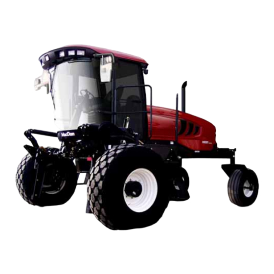
- Page 5 This manual contains information on the MacDon M155 Self-Propelled Windrower which, when paired with one of MacDon’s A Series Auger Headers, certain D and D1 Series Draper Headers, or R and R1 Series Rotary Disc Headers, ably cuts and lays in windrows a variety of grain, hay, and specialty crops.
-
Page 6: Summary Of Changes
Summary of Changes At MacDon, we’re continuously making improvements; occasionally these improvements impact product documentation. The following list provides an account of major changes from the previous version of this document. Internal Use Summary of Change Section Only Technical 3.10.3 Climate Controls, page 54 Removed redundant Refrigerant Oil subtopic. - Page 7 Internal Use Summary of Change Section Only Draining and Cleaning Coolant Tank, page Technical Added note. Clarified procedure. Publications 5.9.8 Inspecting Exhaust System, page Technical Revised title. Publications Rewrote and retitled procedure. Procedure now describes Replacing High Intensity Discharge Technical the process of replacing an HID light, not installing a new Floodlights, page 402 Publications...
-
Page 8: Serial Numbers
Serial Numbers Record the model year and serial number of the windrower and its engine in the fields below. Windrower serial number plate (A) is located on the left side of the main frame near the walking beam. Windrower serial number Year of manufacture Figure 3: Windrower Serial Number Location The engine serial number plate (A) is located on top of the... -
Page 9: Table Of Contents
TABLE OF CONTENTS Declaration of Conformity ..........................i Introduction .............................. iii Summary of Changes........................... iv Serial Numbers............................vi Chapter 1: Safety ............................1 1.1 Safety Alert Symbols ..........................1 1.2 Signal Words ............................2 1.3 General Safety ............................3 1.4 Maintenance Safety ..........................5 1.5 Hydraulic Safety .............................6 1.6 Tire Safety.............................7 1.7 Battery Safety ............................8 1.8 Welding Precautions ..........................9... - Page 10 TABLE OF CONTENTS 3.4 Using Training Seat ..........................44 3.5 Using Seat Belts ........................... 45 3.6 Adjusting Steering Column ........................46 3.7 Exterior Lighting ........................... 47 3.7.1 Auto-Road Lighting........................47 3.7.2 Cab-Forward Lighting........................48 3.7.3 Engine-Forward Lighting........................ 49 3.7.4 High Intensity Discharge Auxiliary Lighting – Option ................50 3.8 Windshield Wipers ..........................
- Page 11 TABLE OF CONTENTS Miscellaneous Operational Information ..................80 3.19.4 Cab Display Module Warning and Alarms ..................81 Engine Warning Lights ......................... 81 Display Warnings and Alarms......................82 3.19.5 Cab Display Module – Configuration Guidelines ................84 3.19.6 Cab Display Module – Configuration Functions ................85 3.19.7 Cab Display Options........................
- Page 12 TABLE OF CONTENTS Testing Reel Up/Down Activate Function Using Cab Display Module ..........136 Testing Header Tilt Activate Function Using Cab Display Module ............138 Testing Knife Drive Circuit Using Cab Display Module ..............139 Testing Draper Drive Circuit Activate Function Using Cab Display Module ........... 141 Testing Reel Drive Circuit Activate Function Using Cab Display Module ..........
- Page 13 TABLE OF CONTENTS 4.4.1 Engaging and Disengaging Header Safety Props ................192 4.4.2 Header Float ..........................194 Float Operating Guidelines ......................194 Checking Float.......................... 195 Float Options ........................... 196 4.4.3 Leveling Header ......................... 198 4.4.4 Header Drive Controls......................... 201 Engaging and Disengaging Header ....................201 Reversing Header ........................
- Page 14 TABLE OF CONTENTS 4.6.2 Reel Settings ..........................289 4.6.3 Adjusting Reel Fore-Aft Position ....................289 4.6.4 Adjusting Reel Height ......................... 290 4.6.5 Reel Speed..........................290 Indexing Reel Speed to Ground Speed ..................290 Adjusting Reel Speed without Indexing ..................293 4.6.6 Draper Speed ..........................
- Page 15 TABLE OF CONTENTS Checking Operator Presence System .................... 326 Checking Engine Interlock ......................327 5.6.3 Ground Speed Lever Adjustments ....................327 Adjusting Ground Speed Lever Lateral Movement ................327 Adjusting Ground Speed Lever Fore-Aft Movement ................ 329 5.6.4 Steering Adjustments........................329 Checking Steering Link Pivots ......................
- Page 16 TABLE OF CONTENTS System Priming ........................365 Priming Fuel System ......................... 366 5.9.6 Engine Cooling System ........................ 367 Inspecting Radiator Cap ......................367 Checking Engine Coolant Strength ....................368 Checking Coolant Level ......................368 Changing Coolant ........................369 Draining and Cleaning Coolant Tank ..................... 369 Adding Coolant ........................
- Page 17 TABLE OF CONTENTS Replacing Bulb in Rear Floodlight....................406 5.10.8 Replacing Bulbs in Red and Amber Lights..................408 5.10.9 Replacing Red Taillights ......................408 5.10.10 Replacing Beacon Lights......................409 5.10.11 Replacing Console Gauge Light....................409 5.10.12 Replacing Cabin Dome Light ..................... 411 5.10.13 Replacing Ambient Light Fixture ....................
- Page 18 TABLE OF CONTENTS Removing Forked Caster Wheel....................440 Installing Forked Caster Wheel ....................441 Removing Formed Caster Wheel ....................442 Installing Formed Caster Wheel....................442 Tightening Caster Wheel Anti-Shimmy Dampeners ................. 443 Ballast Requirements......................... 443 Chapter 6: Troubleshooting........................445 6.1 Engine Troubleshooting ........................445 6.2 Electrical Troubleshooting ........................
- Page 19 TABLE OF CONTENTS 7.4.2 Towing Harness ......................... 464 7.4.3 Weight Box ..........................464 Chapter 8: Reference ..........................465 8.1 Recommended Torque Values ......................465 8.1.1 Torque Specifications........................465 SAE Bolt Torque Specifications ....................465 Metric Bolt Specifications......................467 Metric Bolt Specifications Bolting into Cast Aluminum..............469 Flare-Type Hydraulic Fittings.......................
-
Page 21: Chapter 1: Safety
Chapter 1: Safety Understanding and consistently following these safety procedures will help to ensure the safety of those operating the machine and of bystanders. 1.1 Safety Alert Symbols The safety alert symbol indicates important safety messages in this manual and on safety signs on the machine. This symbol means: •... -
Page 22: Signal Words
SAFETY 1.2 Signal Words Three signal words, DANGER, WARNING, and CAUTION, are used to alert you to hazardous situations. Two signal words, IMPORTANT and NOTE, identify non-safety related information. Signal words are selected using the following guidelines: DANGER Indicates an imminently hazardous situation that, if not avoided, will result in death or serious injury. WARNING Indicates a potentially hazardous situation that, if not avoided, could result in death or serious injury. -
Page 23: General Safety
SAFETY 1.3 General Safety Protect yourself when assembling, operating, and servicing machinery. CAUTION The following general farm safety precautions should be part of your operating procedure for all types of machinery. Wear all protective clothing and personal safety devices that could be necessary for the job at hand. - Page 24 SAFETY • Wear close-fitting clothing and cover long hair. NEVER wear dangling items such as scarves or bracelets. • Keep all shields in place. NEVER alter or remove safety equipment. Ensure that the driveline guards can rotate independently of their shaft, and that they can telescope freely.
-
Page 25: Maintenance Safety
SAFETY 1.4 Maintenance Safety Protect yourself when maintaining machinery. To ensure your safety while maintaining the machine: • Review the operator’s manual and all safety items before operating or performing maintenance on the machine. • Place all controls in Neutral, stop the engine, set the parking brake, remove the ignition key, and wait for all moving parts to stop before servicing, adjusting, or repairing the machine. -
Page 26: Hydraulic Safety
SAFETY 1.5 Hydraulic Safety Protect yourself when assembling, operating, and servicing hydraulic components. • Always place all hydraulic controls in Neutral before leaving the operator’s seat. • Make sure that all components in the hydraulic system are kept clean and in good condition. •... -
Page 27: Tire Safety
SAFETY 1.6 Tire Safety Service tires safely. WARNING • A tire can explode during inflation, causing serious injury or death. • Follow the proper procedures when mounting a tire. Failure to do so can produce an explosion, causing serious injury or death. -
Page 28: Battery Safety
SAFETY 1.7 Battery Safety Understand the risks of working with lead-acid batteries before performing installation or maintenance tasks. WARNING • Keep all sparks and flames away from batteries. The electrolyte fluid in the battery cells emits an explosive gas which can build up over time. •... -
Page 29: Welding Precautions
SAFETY 1.8 Welding Precautions High currents and voltage spikes associated with welding can cause damage to electronic components. Before welding on any part of the windrower or an attached header, disconnect all electronic module harness connections as well as battery cables. -
Page 30: Engine Safety
SAFETY 1.9 Engine Safety For the safety of yourself and others, understand the hazards associated with the engine before operating the machine, or before servicing the engine or nearby components. WARNING Do NOT use aerosol starting aids such as ether when attempting to start the engine. Use of these substances could result in an explosion. -
Page 31: Engine Electronics
SAFETY 1.9.2 Engine Electronics For the safety of yourself and of others, and to prevent damage to the engine control module (ECM), understand the hazards associated with engine electronics. WARNING Tampering with the electronic system or the original equipment manufacturer (OEM) wiring installation is dangerous and could result in injury to people, death, or damage to the equipment. -
Page 32: Safety Signs
• Replacement safety signs are available from your MacDon Dealer Parts Department. Figure 1.19: Operator’s Manual Decal 1.10.1 Installing Safety Decals Replace any safety decals that are worn or damaged. -
Page 33: Understanding Safety Signs
SAFETY 1.11 Understanding Safety Signs Consult this section to learn the hazards that each type of safety sign denotes. MD #166233 Run-over hazard DANGER • Starting the machine while it is in gear can lead to serious injury or death •... - Page 34 SAFETY MD #166441 Loss-of-control hazard DANGER To prevent serious injury or death from losing control of the machine: • It is essential that the machine be operated within its specified weight limits. • Weight on the tail wheels should be greater than 1179 kg (2600 lb.) when the windrower is operated in the cab- forward position.
- Page 35 SAFETY MD #166454 General hazard pertaining to machine operation and servicing DANGER To prevent injury or death from improper or unsafe machine operation: • Read the operator’s manual and follow all safety instructions. • Do NOT allow untrained persons to operate the machine. •...
- Page 36 SAFETY MD #166456 Battery acid hazard WARNING Lead-acid batteries contain corrosive and poisonous acid, which can damage clothing and cause injury or death. To prevent injury: • Wear protective clothing and personal protective devices when handling battery acid. Figure 1.28: MD #166456 215676 Revision A...
- Page 37 SAFETY MD #166457 General hazard pertaining to machine operation and servicing DANGER To prevent injury or death from improper or unsafe machine operation: • Read the operator’s manual and follow all safety instructions. • Do NOT allow untrained persons to operate the machine. •...
- Page 38 Figure 1.31: MD #166463 • If the width of the attached header impedes other vehicle traffic, remove the header and install a MacDon approved weight box onto the windrower. Refer to the windrower and header operator’s manuals for instructions on safely towing the header.
- Page 39 If you must drive the windrower without a header or without a MacDon weight system: • Operate the windrower in the low-speed range. • Avoid slopes.
- Page 40 If you must drive the windrower without a header or without a MacDon weight system: • Operate the windrower in the low-speed range. • Avoid slopes.
- Page 41 SAFETY MD #167504 Emergency exit information ATTENTION To exit the machine in case of an emergency: • Follow the arrow on the sign. Figure 1.36: MD #167504 MD #174436 High-pressure oil hazard WARNING High-pressure hydraulic fluid can penetrate human skin, which can cause serious injury such as gangrene, which can be fatal.
- Page 42 SAFETY MD #306179/306180/306181 Header crushing hazard DANGER To prevent injury or death from the fall of a raised header: • Fully raise the header, stop the engine, remove the key from the ignition, and engage the safety props before going under the header.
-
Page 43: Safety Sign Locations
Safety Sign Locations F G H Figure 40: Safety Sign Locations – Left Cab-Forward Side A - Hazard Sign (MD #135378) B - Cab Door and Rim (MD #166454) C - Oil Reservoir under Hood (MD #166466) D - Exhaust Cover (MD #166450) E - Close to Radiator Cap (MD #166461) F - Fan Shroud (Top) (MD #166450) G - Fan Shroud (Middle) (MD #166451) - Page 44 Figure 41: Safety Signs – Left Cab-Forward Side xxiv 215676 Revision A...
- Page 45 Figure 42: Safety Sign Locations – Right Cab-Forward Side A - Hazard Sign on Seat (MD #115148) B - Lift Linkage (MD #306180/306181) C - Frame (MD #166455) D - Frame (MD #166456) E - Cab Frame (MD #184372) F - Platform (MD #166425) G - Shroud (MD #166451) H - Shroud (MD #166452) J - Hydraulic Reservoir (MD #174436)
- Page 46 Figure 43: Safety Signs – Right Cab-Forward Side xxvi 215676 Revision A...
-
Page 47: Chapter 2: Product Overview
Combined gross vehicle weight CGVW MacDon D50, D60, and D65 rigid draper headers D Series Header MacDon D115, D120, D125, D130, D135, and D140 rigid draper headers for windrowers D1 SP Series Header Double-draper drive Double knife Double-knife drive... - Page 48 ORS, which stands for O-Ring Seal MacDon R80 and R85 Rotary Disc Headers R Series MacDon R113 and R116 Rotary Disc Headers for windrowers R1 SP Series RoHS (Reduction of A directive by the European Union to restrict use of certain hazardous substances (such as...
-
Page 49: Specifications
PRODUCT OVERVIEW 2.2 Specifications Consult this section to learn about the physical characteristics of and the equipment specifications for your windrower. Engine Type Cummins QSB-4.5L CM850 4 cylinder turbo diesel. B20 biodiesel approved. Displacement 4.5 L (275 cu. in.) Rated 148 hp (110 kW) @ 2300 rpm Power Peak... - Page 50 PRODUCT OVERVIEW Primary Manual, external, drawbolt with springs (1 per side). Two inner booster springs (1 per side) adjustment Fine Hydraulic, in-cab switch adjustment Automatic Hydraulic, 3 programmable settings for all headers (deck shift compensation on draper headers) Type Spring/shock suspension Dimensions 1600 mm (63 in.) Width...
- Page 51 PRODUCT OVERVIEW NOTE: Specifications and design are subject to change without notice or obligation to revise previously sold units. Pump locations: • Knife drive pump (A) (closest to engine) • Reel/conveyor pump (B) (or M2 with disc) • Inner gear pump (C) – Oil from the inner gear pump is normally routed directly to the cooler bypass valve and combines with the return flow from the first gear pump.
-
Page 52: Windrower Dimensions
PRODUCT OVERVIEW 2.3 Windrower Dimensions The length and width of your windrower can be specified in several ways, including frame width, wheel-to-wheel width, frame length, and total length. A - Drive Tire Tread B - Drive Tire Hubs C - Drive Tires D - 1160 mm (45 3/4 in.) E - 3378 mm (133 in.) F - 4022 mm (158 5/16 in.) - Page 53 PRODUCT OVERVIEW Table 2.2 Drive Tires (continued) Tread (A) Hubs (B) Tires (C) Tire Size Wheel Position mm (in.) mm (in.) mm (in.) 18.4 x 26 3139 (123 9/16) 3391 (133 1/2) 3639 (143 1/4) bar and turf Inner/inner wide track 600/65R28 Inner/outer (shipping) 3139 (123 9/16)
- Page 54 PRODUCT OVERVIEW A - Caster Tire Tread B - Caster Tire Casters C - 3064 mm (120 9/16 in.) D - 4747 mm (186 7/8 in.) Table 2.3 Caster Tires Tread (D) Casters (E) Tire Size Wheel Position mm (in.) mm (in.) Minimum 2448 (96 7/16)
-
Page 55: Component Location
PRODUCT OVERVIEW 2.4 Component Location Knowing the location and the identity of key windrower components is critical to operating and properly maintaining the machine. Figure 2.2: Front Cab-Forward View A - Header Lift Leg B - Header Float Springs C - Operator’s Station D - Windshield Wiper E - Turn Signal / Hazard Lights F - Taillight Engine-Forward... - Page 56 PRODUCT OVERVIEW Figure 2.3: Rear Cab-Forward View A - Caster Wheel B - Walking Beam C - Taillights - Cab-Forward (Option) D - Engine Compartment Hood E - Windshield Wiper F - Field Lights G - Horn H - Turn Signal / Hazard Lights J - Mirror K - Door L - Drive Wheel...
-
Page 57: Chapter 3: Operator's Station
Chapter 3: Operator’s Station The operator’s station, which includes the seat, the operating console, and the steering column, contains all of the controls necessary to operate the windrower. It allows the Operator to operate the windrower in cab-forward mode (working mode) or in engine-forward mode (transport mode). - Page 58 OPERATOR’S STATION 2. To adjust only the operator console’s fore-aft setting without adjusting its height: Loosen nuts (A) under the console. b. Move the console as needed. Tighten nuts (A). Figure 3.3: Console Fore-Aft Adjustment 215676 Revision A...
-
Page 59: Operator Presence System
OPERATOR’S STATION 3.2 Operator Presence System The operator presence system is a safety feature designed to activate or deactivate certain systems when the Operator is not seated at the operator’s station. These systems are: • Header drive • Engine and transmission 3.2.1 Header Drive The header drive system will only operate if allowed to do so by the operator presence system. -
Page 60: Operator's Seat Adjustments
OPERATOR’S STATION 3.3 Operator’s Seat Adjustments The operator’s seat can be adjusted in several ways so that the Operator remains comfortable while operating the machine. 3.3.1 Adjusting Fore-Aft Position Changing the fore-aft setting moves the operator’s chair closer to or father away from the front of the windrower. 1. -
Page 61: Adjusting Vertical Dampener
OPERATOR’S STATION 3.3.3 Adjusting Vertical Dampener The vertical dampener regulates the degree of shock absorption the seat provides in the up-and-down plane. To increase the seat’s vertical dampening, turn knob (A) counterclockwise. To decrease the seat’s vertical dampening, turn knob (A) clockwise. -
Page 62: Adjusting Fore-Aft Isolator Lock
OPERATOR’S STATION 3.3.5 Adjusting Fore-Aft Isolator Lock The fore-aft isolator provides a degree of shock absorption when the windrower is turned. It can be locked or unlocked. To lock the fore-aft isolator, push lever (A) down. To unlock the fore-aft isolator, push lever (A) up. Figure 3.8: Fore-Aft Isolator Lock 3.3.6 Adjusting Seat Tilt The angle of the seat back relative to the operator’s seat can be adjusted using the seat tilt lever. -
Page 63: Adjusting Armrest Angle
OPERATOR’S STATION 3.3.7 Adjusting Armrest Angle The angle of the armrest relative to the operator’s seat can be adjusted using the knob on the bottom of the armrest. To increase the armrest angle, rotate knob (A) clockwise. To decrease the armrest angle, rotate knob (A) counterclockwise. -
Page 64: Using Training Seat
OPERATOR’S STATION 3.4 Using Training Seat A wall-mounted, fold-up training seat complete with seat belt is provided solely for the purpose of training new Operators. WARNING • The training seat is provided for use by an experienced machine Operator, so that they can train a new Operator on the use of the machine. -
Page 65: Using Seat Belts
OPERATOR’S STATION 3.5 Using Seat Belts The windrower is equipped with seat belts on the operator’s and trainer’s seats. WARNING Seat belts can help ensure your safety when they are properly used and maintained. • Before starting the engine, fasten your seat belt, and ensure that the training seat occupant’s seat belt is securely fastened. -
Page 66: Adjusting Steering Column
OPERATOR’S STATION 3.6 Adjusting Steering Column The position of the steering column can be adjusted to suit each Operator and to make it easier to get in and out of the seat. 1. Hold onto the steering wheel, lift handle (A), and move the steering wheel up or down to the desired position. -
Page 67: Exterior Lighting
OPERATOR’S STATION 3.7 Exterior Lighting The exterior lighting system consists of the field, road, and the beacon and/or clearance lights. These lights can be controlled from a panel in the cab’s headliner. Field/road (A), high/low beam (B), and beacon light (C) switches are located on a panel in the cab headliner. -
Page 68: Cab-Forward Lighting
OPERATOR’S STATION 3.7.2 Cab-Forward Lighting This section explains the lighting defaults with the windrower in cab-forward mode. Table 3.1 Cab-Forward Lighting Auto Road Inactive Auto Road Active Switch Position ⇨⇨ Field Road Field Road Lights ⇩ Field (A) Field (B) ON with high ON with high ON with high... -
Page 69: Engine-Forward Lighting
OPERATOR’S STATION 3.7.3 Engine-Forward Lighting This section explains the lighting defaults with the windrower in engine-forward mode. Table 3.2 Engine-Forward Lighting Auto Road Inactive Auto Road Active Switch Position ⇨⇨ Field Road Field Road Lights ⇓ Field (A) Tail (B) Hazard/turn signal (C) CDM switched CDM switched... -
Page 70: High Intensity Discharge Auxiliary Lighting - Option
OPERATOR’S STATION 3.7.4 High Intensity Discharge Auxiliary Lighting – Option Two optional high intensity discharge (HID) lights (MD #B5596) provide additional lighting during field operation. If installed, the HID auxiliary lights are located on mirror supports (A). They can be activated only when the windrower is in cab-forward mode. -
Page 71: Windshield Wipers
OPERATOR’S STATION 3.8 Windshield Wipers The windrower has two windshield wipers: one in the front, and one in the rear. They can be controlled independently. The windshield wiper controls are located in the cab headliner. The illustration shows the controls when the windrower is in cab-forward mode. -
Page 72: Rearview Mirrors
OPERATOR’S STATION 3.9 Rearview Mirrors The type of rearview mirror available to the Operator depends on whether the windrower is being operated in cab-forward or engine-forward mode. Two outside-mounted, adjustable mirrors (A) provide a rear view when the windrower is in cab-forward mode. A single interior-mounted mirror (B) provides a rear view when the windrower is in engine-forward mode. -
Page 73: Cab Temperature
OPERATOR’S STATION 3.10 Cab Temperature The temperature in the windrower cab is regulated by a climate control system which can provide filtered cool or warm air. The heater shut-off valve must be open for the heater to work properly. The heater/evaporator/blower assembly is located under the cab floor and is accessible from beneath the windrower. 3.10.1 Heater Shut-Off A coolant shut-off valve near the engine allows the cab heater to be isolated from the engine’s cooling system. -
Page 74: Climate Controls
OPERATOR’S STATION 3.10.3 Climate Controls The climate controls in the cab’s headliner allow the Operator to control the blower fan speed, to turn the air conditioning (A/C) on and off, to change the air supply source, and to control the temperature of the blown air. Blower switch (A) –... -
Page 75: Interior Lights
OPERATOR’S STATION 3.11 Interior Lights Two interior lights are provided in the cab for the convenience of the Operator. Low intensity LED light (A) is located directly overhead. It functions only when the windrower’s key is in the RUN position. An ON/OFF switch is located on the light. -
Page 76: Emergency Exit
OPERATOR’S STATION 3.12 Emergency Exit An emergency exit is provided to allow the Operator exit the windrower in case the door is no longer usable. The emergency exit window (indicated by emergency exit decal [A]) is located beside the operator’s station. Figure 3.30: Emergency Exit Sign To open the emergency exit window: 1. -
Page 77: Operator Amenities
OPERATOR’S STATION 3.13 Operator Amenities The operator’s station includes a number of features which make operating the windrower more convenient, such as an auxiliary power outlet and a cup holder. Operator’s console A - Auxiliary power outlet B - Utility tray (under armrest) C - Cigarette lighter D - Ashtray/cup holder E - Utility tray... - Page 78 OPERATOR’S STATION Manual storage Manual storage case (A) is located under the training seat. Figure 3.35: Operator’s Manual Storage Coat hook Coat hook (A) is located above the training seat, left of the Operator. Figure 3.36: Coat Hook 215676 Revision A...
-
Page 79: Radio
OPERATOR’S STATION 3.14 Radio A radio is available as optional equipment from your Dealer. 3.14.1 AM/FM Radio A space is provided in the cab headliner to accommodate the installation of an AM/FM radio. In order to retain the radio settings and the preset memory when the battery disconnect is turned off, install a unit which features non-volatile settings memory. - Page 80 OPERATOR’S STATION Knockout (A) is located on the exterior right cab-forward rear corner post of the cab, under the roof, between the horn and the light. Figure 3.39: Knockout Location in Cab To make your own mount, refer to the dimensions template provided.
-
Page 81: Horn
OPERATOR’S STATION 3.15 Horn The horn allows the Operator to alert bystanders and other vehicle operators. The horn is activated by pushing button (A) on the headliner console. Sound the horn three times prior to starting the engine. Figure 3.41: Horn Button Location Horn (A) is located outside the cab on the rear right cab-forward corner of the cab, under the roof. -
Page 82: Engine Controls And Gauges
OPERATOR’S STATION 3.16 Engine Controls and Gauges The ignition, fuel gauge, engine temperature gauge, and throttle are located on the operator’s console. Ignition switch (A) The features of the windrower which are active depend on the position of the ignition key: •... -
Page 83: Windrower Controls
OPERATOR’S STATION 3.17 Windrower Controls The windrower controls on the operator’s console allow the Operator to control the speed and direction of the windrower, as well as the turn signals and hazard lights. Console controls: Turn signals (A): the turn signal switches activate the turning indicator lights on the windrower and the header. - Page 84 OPERATOR’S STATION The autosteer engagement switch harness has two connectors: GSL SW1 (A) is located in the cab, beneath the floor mat at the engine-end seat position switch. Figure 3.46: Autosteer Harness SW1 GSL SW2 (A) is located beneath the cab, between the fuel tank and the evaporator box.
-
Page 85: Header Controls
Reversing an auger header or a draper header equipped with a conditioner requires the installation of a hydraulic reversing kit on the windrower. Contact your MacDon Dealer for more information. • To engage the header and run it in reverse, push and hold REVERSER button (B), and engage the header by pushing switch (A). -
Page 86: Ground Speed Lever Header Switches
OPERATOR’S STATION 3.18.3 Ground Speed Lever Header Switches Header functions such as the display selection, reel position, header height, and the speed of the reel or discs can be controlled from the switches on the ground speed lever (GSL). The switches on GSL (A) control the most common header functions. -
Page 87: Display Selector Switch
OPERATOR’S STATION Display Selector Switch The display selector switch allows the Operator to choose what information is displayed on the cab display module’s (CDM) top line read-out. Press switch (A) to scroll through the settings. Figure 3.52: Ground Speed Lever Header Position Switches Use the header position switches on the ground speed lever (GSL) to adjust the height of the header. -
Page 88: Reel And Disc Speed Switches
OPERATOR’S STATION Reel and Disc Speed Switches The reel speed switches are used to control the speed of the reel when a draper header is attached to the windrower. When other types of headers are attached to the windrower, the reel speed switches control different header functions. Press and hold switch (A) to increase the reel or the disc speed. - Page 89 OPERATOR’S STATION Draper header with fixed decks / auger header / rotary disc header When a fixed-deck draper header, auger header, or rotary disc header is attached to the windrower, this switch is used to select one of the preprogrammed header float settings. Refer to Float Options, page 196 to learn how to configure these presets.
-
Page 90: Cab Display Module
OPERATOR’S STATION 3.19 Cab Display Module The cab display module (CDM) is a computer located on the windrower operator’s console. It is used to configure and operate the windrower and its attachments. It also supplies the Operator with information about the windrower’s performance and alerts them to any problems encountered during operation. -
Page 91: Header Functions
OPERATOR’S STATION 3.19.2 Header Functions Several header functions such as the header float and the speed of the auger or draper (depending on the type of header attached to the windrower) are controlled from the cab display module (CDM). Figure 3.58: Cab Display Module (CDM) •... -
Page 92: Operating Screens
OPERATOR’S STATION • RETURN-TO-CUT HEIGHT SWITCH (G): this switch allows the Operator to make use of the cutting height preset. Push the switch to enable this feature; push it again to disable it. NOTE: Return-to-cut height switch (G) will light up when this feature is enabled. 3.19.3 Operating Screens The display screen on the cab display module (CDM) reports performance information about the windrower and its attached header. -
Page 93: Engine-Forward, Engine Running
OPERATOR’S STATION Engine-Forward, Engine Running These are the messages which can appear in the cab display module (CDM) when the windrower is in engine-forward mode and the engine is running. Description Display ROAD GEAR (upper line) Indicates that the windrower’s transmission is in the HIGH range Displays the total engine operating time #####.# ENGINE HRS (upper or lower line) #####.# UNIT HRS (upper or lower line) -
Page 94: Cab-Forward, Engine Running, Header Engaged, Auger Header Attached, Index Switch Off
A sensor which can monitor the knife/conditioner circuit pressure can be installed as an optional kit. To monitor the hydraulic pressure of the reel/auger circuit, relocate the sensor per kit instruction MD #169031; this instruction is available from your MacDon Dealer. 215676... -
Page 95: Cab-Forward, Engine Running, Header Engaged, Auger Header Attached, Index Switch On
OPERATOR’S STATION Display (Lower or Upper Line) Description Displays the swath compressor’s height setting(00.0–10.0); fully raised is ##.# SWATH COMPR HT SWATH CO SENSOR This message appears if the swath compressor height sensor is disabled SCROLL SUB-MENU (lower line only) Displays the sub-menu after two to three seconds. -
Page 96: Engine Running, Header Engaged, Auger Header
10. A sensor which can monitor the knife/conditioner circuit pressure can be installed as an optional kit. To monitor the hydraulic pressure of the reel/auger circuit, relocate the sensor per kit instruction MD #169031; this instruction is available from your MacDon Deale 215676... -
Page 97: Cab-Forward, Engine Running, Header Engaged, Draper Header Attached, Index Switch Off
OPERATOR’S STATION Display (Lower or Upper Line) Description ENGINE TEMP ### °F Engine coolant temperature ENGINE TEMP ### °C (if metric) SCROLL Displays sub-menu after 2–3 seconds. Press SELECT to cancel. Scroll through SUB-MENU (lower line only) sub-menu display with CDM switch #### KNIFE SPEED Knife speed is optional ##.# AUGER SPEED... -
Page 98: Cab-Forward, Engine Running, Header Engaged, Draper Header Attached, Index Switch On
11. A sensor which can monitor the knife/conditioner circuit pressure can be installed as an optional kit. To monitor the hydraulic pressure of the reel/auger circuit, relocate the sensor per kit instruction MD #169031; this instruction is available from your MacDon Dealer. 215676... -
Page 99: Cab-Forward, Engine Running, Header Engaged, Rotary Disc Header Attached
12. A sensor which can monitor the knife/conditioner circuit pressure can be installed as an optional kit. To monitor the hydraulic pressure of the reel/auger circuit, relocate the sensor per kit instruction MD #169031; this instruction is available from your MacDon Dealer. 215676... -
Page 100: Miscellaneous Operational Information
MD #169031; this instruction is available from your MacDon Dealer. 14. If the windrower’s road light kit is not installed, the CDM will display the error message E135 LEFT STOP LAMP when the windrower is in cab-forward mode. -
Page 101: Cab Display Module Warning And Alarms
OPERATOR’S STATION Display (Upper Line) Description Indicates that the right turn indicator system is active. This message appears ■ RIGHT TURN > when the right turn arrow on the CDM is pressed when the windrower is in engine-forward mode. ■ HAZARD ■ Indicates that the hazard light system is active Indicates that the header drive is running in reverse HEADER REVERSE... -
Page 102: Display Warnings And Alarms
• DISPLAY: Displays error codes. To learn the precise meaning of an error code, refer to 8.4 Engine Error Codes, page 480 or contact your MacDon Dealer. Display Warnings and Alarms Refer to this table to learn the precise meaning of the alarms, lights, and error messages produced by the cab display module (CDM). - Page 103 OPERATOR’S STATION Display (A) Flashing Description Alarm Tone R80/R85 - Engine rpm above DISENGAGE HEADER 1800 rpm when attempting to None RE-ENGAGE <1800 RPM> engage the header Single loud tone for ten seconds; Engine air filter requires servicing ENGINE AIR FILTER tone repeats every 30 minutes until the condition is corrected Ongoing intermittent moderate...
-
Page 104: Cab Display Module - Configuration Guidelines
NOTE: Contact your MacDon Dealer for information about software updates to the electronic modules. Your Dealer will have access to the latest software upgrades and the necessary interface tools to install the software. -
Page 105: Cab Display Module - Configuration Functions
OPERATOR’S STATION 3.19.6 Cab Display Module – Configuration Functions Use the cab display module’s (CDM) configuration functions to set up the windrower, to change the appearance of the CDM itself, to enter diagnostic mode, and to calibrate the header sensors. Figure 3.62: CDM A - Side Display B - Main Display... -
Page 106: Cab Display Options
Program Switch: Pressing this switch along with the SELECT switch puts the CDM into programming mode. NOTE: Contact your MacDon Dealer for information about software updates to the electronic modules. Your Dealer will have access to the latest software upgrades and the necessary interface tools to install the software. -
Page 107: Changing Windrower Display Units
OPERATOR’S STATION 3. Press SELECT (A) until CAB DISPLAY SETUP? appears on the upper line. • NO/YES will appear on the lower line. CAB DISPLAY SETUP? CXXX MXXX NO/YES Figure 3.64: Cab Setup Display 4. Press right arrow (C) to select YES. Press SELECT (D). •... -
Page 108: Adjusting Cab Display Buzzer Volume
OPERATOR’S STATION 3. Press SELECT (B) until CAB DISPLAY SETUP? is displayed on the upper line. • NO/YES will appear on the lower line. CAB DISPLAY SETUP? CXXX MXXX NO/YES 4. Press right arrow (A) to select YES. Press SELECT (B). •... -
Page 109: Adjusting Cab Display Backlighting
OPERATOR’S STATION 3. Press SELECT (B) until CAB DISPLAY SETUP? appears on the upper line. • NO/YES will appear on the lower line. CAB DISPLAY SETUP? CXXX MXXX NO/YES 4. Press right arrow (A) to select YES. Press SELECT (B). •... -
Page 110: Adjusting Cab Display Contrast
OPERATOR’S STATION 3. Press SELECT (B) until CAB DISPLAY SETUP? appears on the upper line. • NO/YES will appear on the lower line. CAB DISPLAY SETUP? CXXX MXXX NO/YES 4. Press right arrow (A) to select YES. Press SELECT (B). •... -
Page 111: Configuring Windrower
OPERATOR’S STATION 3. Press SELECT (B) until CAB DISPLAY SETUP? appears on the upper line. • NO/YES will appear on the lower line. CAB DISPLAY SETUP? CXXX MXXX NO/YES 4. Press right arrow (A) to select YES. Press SELECT (B). •... -
Page 112: Setting Knife Overload Speed
OPERATOR’S STATION 1. Turn the ignition key to the RUN position, or start the engine. 2. Press PROGRAM (A) and SELECT (C) simultaneously on the WINDROWER SETUP? CXXX CDM to enter programming mode. MXXX NO/YES • WINDROWER SETUP? will appear on the upper line. •... -
Page 113: Setting Rotary Disc Overload Speed
OPERATOR’S STATION To set the knife overload speed: 1. Turn the ignition key to the RUN position, or start the engine. 2. Press PROGRAM (A) and SELECT (C) simultaneously on the WINDROWER SETUP? CXXX CDM to enter programming mode. MXXX NO/YES •... -
Page 114: Setting Hydraulic Overload Pressure
OPERATOR’S STATION To set the rotary disc overload speed: 1. Turn the ignition key to the RUN position, or start the engine. 2. Press PROGRAM (A) and SELECT (C) on the CDM to enter WINDROWER SETUP? CXXX programming mode. MXXX NO/YES •... -
Page 115: Setting Header Index Mode
OPERATOR’S STATION To set the hydraulic overload pressure setting: 1. Turn the ignition key to the RUN position, or start the engine. 2. Press PROGRAM (A) and SELECT (C) simultaneously on the WINDROWER SETUP? CXXX cab display module (CDM) to enter programming mode. MXXX NO/YES •... -
Page 116: Setting Return To Cut Mode
OPERATOR’S STATION 1. Turn the ignition key to the RUN position, or start the engine. 2. Press PROGRAM (A) and SELECT (C) simultaneously on the WINDROWER SETUP? CXXX CDM to enter programming mode. MXXX NO/YES • WINDROWER SETUP? will appear on the upper line. •... -
Page 117: Setting Auto Raise Height
OPERATOR’S STATION 2. Press PROGRAM (A) and SELECT (C) simultaneously on the CDM to enter programming mode. • WINDROWER SETUP? will appear on the upper line. WINDROWER SETUP? CXXX • NO/YES will appear on the lower line. MXXX NO/YES 3. Press right arrow (B) to select YES. Press SELECT (C). •... -
Page 118: Configuring Double Windrow Attachment Controls
OPERATOR’S STATION 1. Turn the ignition key to the RUN position, or start the engine. 2. Press PROGRAM (A) and SELECT (C) on the CDM to enter WINDROWER SETUP? CXXX programming mode. MXXX NO/YES • WINDROWER SETUP? will appear on the upper line. •... - Page 119 OPERATOR’S STATION 1. Turn the ignition key to the RUN position, or start the engine. 2. Press PROGRAM (A) and SELECT (C) simultaneously on the WINDROWER SETUP? CXXX cab display module (CDM) to enter programming mode. MXXX NO/YES • WINDROWER SETUP? appears on the upper line. •...
-
Page 120: Activating Hydraulic Center-Link
OPERATOR’S STATION 7. Press right arrow (C) to select YES. Press SELECT (D). • DWA AUTO UP/DOWN? appears on the upper line. • NO/YES appears on the lower line. DWA AUTO UP / DOWN? CXXX MXXX NO/YES NOTE: If YES is selected, the DWA Auto-Up function will be activated by the GSL reel fore-aft button. -
Page 121: Activating Rotary Disc Header Drive Hydraulics
OPERATOR’S STATION Activating Rotary Disc Header Drive Hydraulics To use a rotary disc header with the windrower, you must activate the header drive hydraulics option on the windrower’s cab display module (CDM). NOTE: This procedure requires installation of the optional Disc Drive Kit (MD #B4657). 7.3.9 R80 and R85 Rotary Header Drive Hydraulics –... -
Page 122: Activating Swath Compressor
SELECT (D) to proceed to next WINDROWER SETUP action. Figure 3.101: Header Cut Width Activating Swath Compressor An optional swath compressor (MD #C2061) is available through your MacDon Dealer. Before the swath compressor can be used, it must be activated in the cab display module (CDM). NOTE: •... - Page 123 OPERATOR’S STATION 1. Turn the ignition key to the RUN position, or start the engine. 2. Press PROGRAM (A) and SELECT (C) simultaneously on the WINDROWER SETUP? CXXX CDM to enter programming mode. MXXX NO/YES • WINDROWER SETUP? appears on the upper line. •...
-
Page 124: Activating Hay Conditioner
OPERATOR’S STATION 10. Press switch (B) on the console to lower the swath compressor. • CALIBRATING SWATH appears on the upper line. • The messages FORM DOWN and HOLD appear on the lower line. • SWATH FORM COMPLETE flashes for two seconds on the lower line (accompanied by a buzzer tone) when the calibration procedure is complete. -
Page 125: Displaying Reel Speed
OPERATOR’S STATION 4. Press SELECT (C) until HAY CONDITIONER? appears on the upper line. • NO/YES will appear on the lower line. HAY CONDITIONER CXXX MXXX NO/YES 5. Press right arrow (B) to select YES. Press SELECT (C). 6. Press PROGRAM (A) to exit programming mode or press SELECT (C) to proceed to the next WINDROWER SETUP option. -
Page 126: Setting Tire Size
OPERATOR’S STATION 4. Press SELECT (D) until HEADER REEL SPEED? appears on the upper line. • RPM/MPH or RPM/KPH will appear on the lower line. HEADER REEL SPEED CXXX MXXX RPM/MPH 5. Press left arrow (B) or right arrow (C) to select either IMPERIAL or METRIC units. -
Page 127: Setting Engine Intermediate Speed Control
OPERATOR’S STATION 6. Press PROGRAM (A) to exit programming mode or press SELECT (D) to proceed to the next WINDROWER SETUP option. Setting Engine Intermediate Speed Control The engine’s Intermediate Speed Control (ISC) feature provides three selectable engine speeds (1900, 2050, or 2200 rpm) for reduced load conditions. -
Page 128: Clearing Sub-Acres
OPERATOR’S STATION 6. Press right arrow (C) to cycle between the setting options. Press HAZARD (B) to confirm the desired setting. 7. Press SELECT (D). PRESS HAZARD TO SET CXXX MXXX ISC RPM #### • EXIT ENGINE ISC? will appear on the upper line. •... -
Page 129: Activating Header Tilt Control Lockout
OPERATOR’S STATION Activating Header Tilt Control Lockout Activating the header tilt control lockout in the windrower’s cab display module (CDM) prevents unauthorized Operators from changing the angle of the attached header. NOTE: • The header MUST be attached to the windrower to perform this procedure. The cab display module (CDM) automatically adjusts its programming for each header. -
Page 130: Activating Header Float Control Lockout
OPERATOR’S STATION 6. Press SELECT (D) until HEADER TILT appears on the upper line. • ENABLED/LOCKED will appear on the lower line. HEADER TILT CXXX MXXX ENABLED/LOCKED 7. Press left arrow (B) to enable the use of the HEADER TILT control switch. -
Page 131: Activating Reel Fore-Aft Control Lockout
OPERATOR’S STATION 4. Press SELECT (B) until SET CONTROL LOCKS? appears on the upper line. • NO/YES will appear on the lower line. CXXX SET CONTROL LOCKS? MXXX NO/YES 5. Press right arrow (A) to select YES. Press SELECT (B). Figure 3.120: Control Locks 6. - Page 132 OPERATOR’S STATION To activate the reel fore-aft control lockout: 1. Turn the ignition key to the RUN position, or start the engine. 2. Press PROGRAM (A) and SELECT (C) simultaneously on the WINDROWER SETUP? CXXX CDM to enter programming mode. MXXX NO/YES •...
-
Page 133: Activating Draper Speed Control Lockout
OPERATOR’S STATION Activating Draper Speed Control Lockout Activating the header draper speed control lockout in the windrower’s cab display module (CDM) prevents unauthorized Operators from changing the draper speed setting of the attached header. NOTE: • This procedure applies to windrowers with attached draper headers only. •... -
Page 134: Activating Auger Speed Control Lockout
OPERATOR’S STATION 6. Press SELECT (D) until DRAPER SPEED appears on the upper line. • ENABLED/LOCKED will appear on the lower line. DRAPER SPEED CXXX MXXX ENABLED/LOCKED 7. Press left arrow (B) to enable the DRAPER SPEED control switch, or press right arrow (C) to lock the DRAPER SPEED control switch. -
Page 135: Activating Knife Speed Control Lockout
OPERATOR’S STATION 4. Press SELECT (B) until SET CONTROL LOCKS? appears on the upper line. • NO/YES will appear on the lower line. CXXX SET CONTROL LOCKS? MXXX NO/YES 5. Press right arrow (A) to select YES. Press SELECT (B). Figure 3.129: Control Locks 6. - Page 136 OPERATOR’S STATION 1. Turn the ignition key to the RUN position, or start the engine. 2. Press PROGRAM (A) and SELECT (C) simultaneously on the WINDROWER SETUP? CXXX CDM to enter programming mode. MXXX NO/YES • WINDROWER SETUP? will appear on the upper line. •...
-
Page 137: Activating Rotary Disc Speed Control Lockout
OPERATOR’S STATION Activating Rotary Disc Speed Control Lockout Activating the rotary disc speed control lockout in the windrower’s cab display module (CDM) prevents unauthorized Operators from changing the disc speed of the attached rotary header. NOTE: • This procedure applies to windrowers with attached rotary disc headers only. •... -
Page 138: Activating Reel Speed Control Lockout
OPERATOR’S STATION 6. Press SELECT (D) until DISK SPEED appears on the upper line. • ENABLED/LOCKED will appear on the lower line. DISK SPEED CXXX MXXX ENABLED/LOCKED 7. Press left arrow (B) to enable the DISK SPEED control switch, or press right arrow (C) to lock the DISK SPEED control switch. -
Page 139: Displaying Active Cab Display Lockouts
OPERATOR’S STATION 4. Press SELECT (B) until SET CONTROL LOCKS? appears on the upper line. • NO/YES will appear on the lower line. CXXX SET CONTROL LOCKS? MXXX NO/YES 5. Press right arrow (A) to select YES. Press SELECT (B). Figure 3.138: Control Locks 6. - Page 140 OPERATOR’S STATION 4. Press SELECT (B) until VIEW CONTROL LOCKS? appears on the upper line. • NO/YES will appear on the lower line. VIEW CONTROL LOCKS CXXX MXXX NO/YES 5. Press right arrow (A) to select YES. Press SELECT (B). HEADER TILT will appear on the upper line.
-
Page 141: Calibrating Header Sensors
OPERATOR’S STATION 3.19.11 Calibrating Header Sensors When a new header is attached to the windrower, the header’s sensors must be calibrated using the cab display module (CDM) so that their output can be correctly interpreted by the windrower control module (WCM). Calibrating Header Height Sensor The header height sensor can be calibrated by accessing the cab display module’s (CDM) WINDROWER SETUP menu. - Page 142 OPERATOR’S STATION 6. Press and hold HEADER UP button (A) on the ground speed lever (GSL). • CALIBRATING HEIGHT will appear on the upper line. • RAISE HEADER HOLD will appear on the lower line. NOTE: The word HOLD will flash during calibration. RAISE HEADER DONE will display on the lower line once calibration is complete.
-
Page 143: Calibrating Header Tilt Sensor
OPERATOR’S STATION Calibrating Header Tilt Sensor The header tilt sensor can be calibrated by accessing the cab display module’s (CDM) WINDROWER SETUP menu. The calibration procedure must be completed for the sensor to be correctly calibrated. NOTE: • The header must be attached to the windrower to perform this procedure. The cab display module (CDM) automatically adjusts its programming for each header. - Page 144 OPERATOR’S STATION 6. Press and hold HEADER TILT EXTEND button (A) on the ground speed lever (GSL). • CALIBRATING TILT will appear on the upper line. • EXTEND TILT HOLD will appear on the lower line. NOTE: The word HOLD will flash during calibration. HEADER TILT DONE will display on the lower line once calibration is complete.
-
Page 145: Calibrating Header Float Sensors
OPERATOR’S STATION Calibrating Header Float Sensors The header float sensors can be calibrated by accessing the cab display module’s (CDM) WINDROWER SETUP menu. The calibration procedure must be completed for the sensors to be correctly calibrated. NOTE: • The header must be attached to the windrower to perform this procedure. The cab display module (CDM) automatically adjusts its programming for each header. - Page 146 OPERATOR’S STATION 4. Press right arrow (B) to select YES. Press SELECT (C). • TO CALIBRATE SELECT will appear on the upper line. CALIBRATING FLOAT CXXX 5. Press left arrow (A) or right arrow (B) until HEADER FLOAT MXXX PRESS FLOAT + TO START appears on the lower line.
-
Page 147: Calibrating Swath Compressor Sensor
OPERATOR’S STATION 3.19.12 Calibrating Swath Compressor Sensor The swath compressor’s sensor can be calibrated by accessing the cab display module’s (CDM) WINDROWER SETUP menu. The calibration procedure must be completed for the sensor to be correctly calibrated. This procedure applies only to windrowers equipped with a swath compressor. - Page 148 OPERATOR’S STATION • SWATH SENSOR CAL will appear on the upper line. • PRESS SWATH DOWN will appear on the lower line. SWATH SENSOR CAL C### M### PRESS SWATH DOWN Figure 3.160: Swath Compressor Sensor Calibration 7. Press and hold button (A) to lower the swath compressor. •...
-
Page 149: Troubleshooting Windrower Problems
OPERATOR’S STATION 3.19.13 Troubleshooting Windrower Problems The cab display module (CDM) is a useful troubleshooting tool, providing information about sensor status and error codes. Displaying Windrower and Engine Error Codes The cab display module (CDM) stores any error codes that occur. Follow this procedure to review the CDM’s stored error codes. -
Page 150: Enabling Or Disabling Header Sensors
OPERATOR’S STATION 10. Press right arrow (C) to select YES. Press SELECT (D). 11. Press left arrow (B) or right arrow (C) to cycle through the last ten recorded engine error codes until EXIT ENGINE VIEW ENGINE CODES? CXXX CODES appears. MXXX NO/YES •... -
Page 151: Displaying Header Sensor Input Signals
OPERATOR’S STATION 5. Press SELECT (B) until ENTER SENSOR SETUP? appears on the upper line. • NO/YES will appear on the lower line. DIAGNOSTIC MODE? CXXX MXXX NO/YES 6. Press right arrow (A) to select YES. Press SELECT (B). • KNIFE SPEED SENSOR will appear on the lower line. •... - Page 152 OPERATOR’S STATION 1. Turn the ignition key to the RUN position, or start the engine. 2. Press PROGRAM (A) and SELECT (B) simultaneously on the WINDROWER SETUP? CXXX CDM to enter programming mode. MXXX NO/YES • WINDROWER SETUP? will appear on the upper line. •...
-
Page 153: Forcing Header Identification
OPERATOR’S STATION Forcing Header Identification The windrower’s cab display module (CDM) must recognize the header model in order to proceed with troubleshooting. If the header wiring has been damaged, or if no header is available, you can force the windrower control module (WCM) to behave as if a header is attached to the windrower by manually inputting a header identification code. -
Page 154: Troubleshooting Header Problems
OPERATOR’S STATION 5. Press SELECT (B) until FORCE HEADER TYPE? appears on the upper line. • NO/YES will appear on the lower line. FORCE HEADER TYPE? CXXX MXXX NO/YES 6. Press right arrow (A) to select YES. Press SELECT (B). •... - Page 155 OPERATOR’S STATION 1. Start the engine. 2. Press PROGRAM (A) and SELECT (B) simultaneously on the CDM to enter programming mode. Press SELECT (B). WINDROWER SETUP? CXXX MXXX NO/YES • WINDROWER SETUP? will appear on the upper line. Figure 3.176: CDM Programming Buttons 3.
-
Page 156: Testing Reel Up/Down Activate Function Using Cab Display Module
OPERATOR’S STATION 7. Press SELECT (D) until ACTIVATE HEADER HT appears on the upper line. • DOWN/UP will appear on the lower line. ACTIVATE HEADER HT CXXX MXXX DOWN/UP 8. Press and hold left arrow (B) to lower the header, or press and hold right arrow (C) to raise the header. - Page 157 OPERATOR’S STATION 3. Press SELECT (B) until DIAGNOSTIC MODE? appears on the upper line. • NO/YES will appear on the lower line. DIAGNOSTIC MODE? CXXX MXXX NO/YES 4. Press right arrow (A) to select YES. Press SELECT (B). Figure 3.181: Diagnostic Functions 5.
-
Page 158: Testing Header Tilt Activate Function Using Cab Display Module
OPERATOR’S STATION Testing Header Tilt Activate Function Using Cab Display Module It may be necessary to use the cab display module (CDM) to change the angle of the attached header, rather than using the header tilt controls on the ground speed lever (GSL). This procedure is used to test the functionality of this feature. NOTE: •... -
Page 159: Testing Knife Drive Circuit Using Cab Display Module
OPERATOR’S STATION 5. Press SELECT (B) until ACTIVATE FUNCTIONS? appears on the upper line. • NO/YES will appear on the lower line. ACTIVATE FUNCTIONS? CXXX MXXX NO/YES 6. Press right arrow (A) to select YES. Press SELECT (B). Figure 3.186: Functions 7. - Page 160 OPERATOR’S STATION 1. Start the engine. 2. Press PROGRAM (A) and SELECT (B) simultaneously on the cab display module (CDM) to enter programming mode. WINDROWER SETUP? CXXX Press SELECT (B). MXXX NO/YES • WINDROWER SETUP? will appear on the upper line. Figure 3.188: CDM Programming Buttons 3.
-
Page 161: Testing Draper Drive Circuit Activate Function Using Cab Display Module
OPERATOR’S STATION 7. Press SELECT (E) until KNIFE DRIVE SPD XXXX appears on the upper line. 8. Press and hold HAZARD (C) button. KNIFE DRV SPD XXXX CXXX MXXX • Press left arrow (B) to decrease the knife speed. • Press right arrow (D) to increase the knife speed. IMPORTANT: Do NOT overspeed the knife drive. - Page 162 OPERATOR’S STATION 3. Press SELECT (B) until DIAGNOSTIC MODE? appears on the upper line. • NO/YES will appear on the lower line. DIAGNOSTIC MODE? CXXX MXXX NO/YES 4. Press right arrow (A) to select YES. Press SELECT (B). Figure 3.193: Diagnostic Functions 5.
-
Page 163: Testing Reel Drive Circuit Activate Function Using Cab Display Module
OPERATOR’S STATION Testing Reel Drive Circuit Activate Function Using Cab Display Module The cab display module (CDM) can be used to test the reel drive circuit, rather than using the controls on the operator’s station. IMPORTANT: Do NOT overspeed the reel drive. Overspeeding can lead to vibration, belt failures, or other overspeeding-related problems. -
Page 164: Testing Rotary Disc Drive Circuit Activate Function Using Cab Display Module
OPERATOR’S STATION 5. Press SELECT (B) until ACTIVATE FUNCTIONS? appears on the upper line. • NO/YES will appear on the lower line. ACTIVATE FUNCTIONS? CXXX MXXX NO/YES 6. Press right arrow (A) to select YES. Press SELECT (B). • ACTIVATE HEADER HT will appear on the upper line. Figure 3.198: Functions 7. - Page 165 OPERATOR’S STATION 1. Start the engine. 2. Press PROGRAM (A) and SELECT (B) simultaneously on the CDM to enter programming mode. WINDROWER SETUP? CXXX MXXX NO/YES • WINDROWER SETUP? will appear on the upper line. Figure 3.200: CDM Programming Buttons 3.
-
Page 166: Testing Double Windrow Attachment Drive Activate Function Using Cab Display Module
OPERATOR’S STATION 7. Press SELECT (E) until DISC DRV SPD XXXX appears on the upper line. 8. Press and hold HAZARD button (C). DISC DRV SPD XXXX CXXX MXXX • Press left arrow (B) to decrease the disc speed. • Press right arrow (D) to increase the disc speed. IMPORTANT: Do NOT overspeed the disc drive. - Page 167 OPERATOR’S STATION 3. Press SELECT (B) until DIAGNOSTIC MODE? appears on the upper line. • NO/YES will appear on the lower line. DIAGNOSTIC MODE? CXXX MXXX NO/YES 4. Press right arrow (A) to select YES. Press SELECT (B). Figure 3.205: Diagnostic Functions 5.
-
Page 168: Testing Reel Fore-Aft Activate Function Using Cab Display Module
OPERATOR’S STATION Testing Reel Fore-Aft Activate Function Using Cab Display Module The cab display module (CDM) can be used to test the reel fore-aft circuit, rather than using the controls on the operator’s station. NOTE: • The windrower must be attached to a header to perform this procedure. For more information, refer to 4.5 Attaching and Detaching Headers, page 215. -
Page 169: Activating Hydraulic Purge Using Cab Display Module
OPERATOR’S STATION 5. Press SELECT (B) until ACTIVATE FUNCTIONS? appears on the upper line. • NO/YES will appear on the lower line. ACTIVATE FUNCTIONS? CXXX MXXX NO/YES 6. Press right arrow (A) to select YES. Press SELECT (B). Figure 3.210: Functions 7. - Page 170 OPERATOR’S STATION 1. Start the engine. 2. Press PROGRAM (A) and SELECT (B) simultaneously on the cab display module (CDM) to enter programming mode. WINDROWER SETUP? CXXX MXXX NO/YES • WINDROWER SETUP? will appear on the upper line. Figure 3.212: CDM Programming Buttons 3.
-
Page 171: Engine Error Codes
OPERATOR’S STATION 7. Press SELECT (B) until ACTIVATE HYD PURGE? appears on the upper line. • NO/YES will appear on the lower line. TO ACTIVATE PURGE CXXX MXXX PRESS AND HOLD 8. Press right arrow (A) to select YES. Press SELECT (B). •... -
Page 173: Chapter 4: Operation
Chapter 4: Operation Safely operating your machine requires familiarizing yourself with its capabilities. 4.1 Owner/Operator Responsibilities Owning and operating heavy equipment comes with certain duties. CAUTION • It is your responsibility to read and understand this manual completely before operating the windrower. Contact your Dealer if an instruction is not clear to you. -
Page 174: Symbol Definitions
OPERATION 4.2 Symbol Definitions These symbols are used to provide at-a-glance information on critical windrower performance parameters. Ensure that you are familiar with the meaning of these symbols before operating the windrower. 4.2.1 Engine Functions These symbols, found on the console, indicate that the button or indicator on which the symbol is found pertains to a particular windrower engine function. -
Page 175: Windrower Operating Symbols
OPERATION 4.2.2 Windrower Operating Symbols These symbols, found on the console, indicate that the button or indicator on which the symbol is found pertains to a particular windrower function. Figure 4.2: Windrower Operating Symbols A - Turn Signals B - Hazard Warning Lights C - Forward D - Neutral E - Reverse... -
Page 176: Header Functions
OPERATION 4.2.3 Header Functions These symbols, found on the console, indicate that the button or indicator on which the symbol is found pertains to a particular header function. Figure 4.3: Header Function Symbols Program Header Index Return to Cut Conveyor/Auger Speed Float Left Float Right Reel Speed... -
Page 177: Operating Windrower
OPERATION 4.3 Operating Windrower Safely operating your machine requires familiarizing yourself with its capabilities. 4.3.1 Operational Safety Follow all the safety and operational instructions provided in this manual when operating the windrower. CAUTION Follow these safety precautions: • Wear close-fitting clothing and protective shoes with slip resistant soles. -
Page 178: Preseason Checks / Annual Service
OPERATION • Operate the engine at moderate load and avoid extremely heavy or light loading for longer than five minutes. • Avoid unnecessary idling. If the engine will be idling longer than five minutes after reaching operating temperature, shut off the engine. •... -
Page 179: Cycling Air Conditioning Compressor Coolant
OPERATION 1. Perform the following checks: Drain off any excess hydraulic oil added for storage purposes. Refer to 5.11.3 Changing Hydraulic Oil, page 420. b. Remove the plastic bags and/or tape from all sealed openings (for example: the air cleaner intake, the exhaust pipe, or the fuel tank). -
Page 180: Engine Operation
OPERATION 4. Clean all lights and reflective surfaces. 5. Perform the specified daily maintenance procedures. For instructions, refer to 5.1 Maintenance Schedule/Record, page 311. 4.3.5 Engine Operation Refer to this section to learn how to start, operate, and shut down the windrower’s engine. Starting Engine Carefully review this procedure before attempting to start the engine—it contains important information pertinent to the safety of the Operator and the integrity of the engine ignition system. - Page 181 OPERATION 2. Ensure that lock (A) at the base of the steering column is engaged in either the cab-forward or the engine-forward position. 3. Move ground speed lever (GSL) (B) into the N-DETENT position. 4. Turn the steering wheel until it locks. NOTE: It may be possible to move the steering wheel slightly in the locked position.
-
Page 182: Engine Warm-Up
OPERATION NOTE: When the ambient temperature is below 5°C (40°F), follow the normal starting procedure. The engine will cycle through a period where it appears to labor until the engine warms up. The throttle will be unresponsive during this time, because the engine is now in WARM UP mode. -
Page 183: Filling Fuel Tank
OPERATION IMPORTANT: Before stopping the engine, allow the engine to run at low idle for approximately 5 minutes. This will allow heated engine parts to cool down, and will allow the turbocharger to slow down while engine oil pressure is available. 1. -
Page 184: Engine Temperature
OPERATION 3. Clean the area around filler cap (A). 4. Turn cap handle (B) counterclockwise until it is loose. Remove the cap. 5. Fill the tank with approved fuel. Refer to the inside back cover of this manual for the recommended fuel. IMPORTANT: Do NOT fill the tank completely—space is required for expansion. -
Page 185: Cab Display Module Voltage Display
OPERATION Cab Display Module Voltage Display The electrical system’s voltage is displayed on the cab display module (CDM) when this option is selected with the SELECT button on the ground speed lever (GSL) handle or the SELECT switch on the CDM. Refer to the table below for information on what the various voltage readings might indicate about the status of the electrical system. -
Page 186: Driving Windrower
WARNING Avoid driving the machine with the header removed. Removing the header decreases the weight on the drive wheels, reducing steering control. If you must drive the machine with the header removed and without a MacDon weight system: • Use the windrower’s low-speed range. -
Page 187: Entering And Exiting Windrower
OPERATION WARNING When operating the windrower on an incline: • Lower the header. • Reduce the windrower’s ground speed. • Move the GROUND SPEED RANGE switch to L (low range). • If the windrower’s ground speed is greater than or equal to 40 km/h (25 mph), the CDM will display a warning message (SLOW DOWN) and will emit a tone. -
Page 188: Driving Forward In Cab-Forward Mode
OPERATION Swing-away platforms and stairs (A) are provided on both sides of the windrower to accommodate cab-forward and engine- forward access to the operator’s station, as well as several maintenance tasks. The left cab-forward side platform is shown in the rearward (cab-forward) position. -
Page 189: Driving In Reverse In Cab-Forward Mode
OPERATION 1. Move GSL (A) to the N-DETENT position. The engine can be running. IMPORTANT: If the GSL is NOT in the N-DETENT position, the GSL cable may be damaged when you swivel the operator’s station. 2. Pull up and hold knob (B) to release latch (C) at the base of the steering column. -
Page 190: Driving Forward In Engine-Forward Mode
OPERATION 1. Move GROUND SPEED RANGE switch (A) to L (the low- range position). 2. Move throttle lever (B) to a mid-range position. NOTE: Steering will be less sensitive when the windrower is operating in the low-speed range, and the engine speed will be reduced. - Page 191 OPERATION 1. Place ground speed lever (GSL) (A) in the N-DETENT position and lock the steering wheel. The engine can be running. IMPORTANT: If the GSL is NOT in the N-DETENT position, the GSL cable may be damaged when you swivel the operator’s station. 2.
-
Page 192: Driving In Reverse In Engine-Forward Mode
OPERATION Driving in Reverse in Engine-Forward Mode Ensure that the windrower’s GROUND SPEED RANGE switch is in the low position before attempting to operate in reverse. Be aware that the steering wheel will produce the opposite response in the direction of the windrower from that produced when it is operating in the forward direction. -
Page 193: Stopping
OPERATION 1. Move ground speed lever (GSL) (A) out of the N-DETENT position to a moderate setting. 2. Slowly turn the steering wheel in the direction in which you would like the windrower to turn. The windrower will pivot between the drive wheels. 3. -
Page 194: Adjusting Caster Tread Width
OPERATION 4.3.7 Adjusting Caster Tread Width The windrower’s rear casters can be moved closer together. This allows the windrower to be loaded onto a trailer and shipped without having to remove the casters entirely. A narrower tread width also suits windrowers paired with smaller headers, by allowing more space for the uncut crop. -
Page 195: Transporting
OPERATION IMPORTANT: The caster wheels must be an equal distance (as indicated by [A]) from the center of the windrower. Figure 4.30: Adjustable Caster Wheels 5. Line up the holes in the walking beam. Install shorter bottom bolts (B). 6. Position bracket (A) and install back bolts (C). 7. - Page 196 • Display a slow-moving vehicle emblem and flashing warning lights, unless these actions are prohibited by law. • If the width of the attached header impedes other vehicle traffic, remove the header and install a MacDon- approved weight box on the windrower. This will allow the windrower to be driven safely on roadways without an attached header.
- Page 197 OPERATION 6. Push the LIGHT switch to ROAD position (A) to activate the lamps. Always use these lamps when operating the windrower on public roads. For more information, refer to 3.7 Exterior Lighting, page NOTE: If the auto-road light feature is activated (that is, when the windrower is in the engine- or cab-forward mode, is out of park, is in high range switch position, and has the header disengaged), only the two front corner field lights will turn...
-
Page 198: Towing Header With Windrower
Towing Header with Windrower The windrower can be used to tow a MacDon draper header that has the slow speed transport option installed. Ensure that the optional weight box or an approved header transporter is installed on the windrower to transfer the windrower’s weight to the lift arms. - Page 199 OPERATION Figure 4.38: M Series Windrower Table 4.2 Maximum Weight 21,500 Maximum GVW (includes mounted implements) 9750 Maximum CGVW (includes towed and mounted implements) 10,480 23,100 Weight (A) on both drive wheels 18,750 8500 Maximum 10,070 Minimum 4570 Maximum weight (B) on both caster tires 2750 6050 Converting Windrower from Field to Transport Mode...
- Page 200 OPERATION 3. Retrieve the temporary lift pin from its storage location on the weight box and install it into rear hole (A) at the top of the lift arms. This provides additional lift height so that the transport wheels can easily be deployed. DANGER Ensure that all bystanders have cleared the area.
- Page 201 OPERATION 10. Remove pins (A) from the lower end of the lift linkages. NOTE: Pins (A) are also used to secure the weight box to the windrower linkage. 11. Release the safety props on the header lift cylinders. For instructions, refer to 4.4.1 Engaging and Disengaging Header Safety Props, page 192.
- Page 202 OPERATION 18. Lift the center-link off of the header pin. NOTE: If the center-link self-alignment kit is installed, start the engine and raise the center-link using the REEL UP switch on the ground speed lever (GSL). 19. Slowly back the windrower away from the header. 20.
- Page 203 OPERATION 3. Disconnect wiring connector (A) at the front wheel. Figure 4.47: Header Transport Wheel 4. Remove clevis pin (D). 5. Push latch (C) and lift tow-bar (A) from the hook. Release the latch and replace the clevis pin. 6. Unhook the tow-bar from the weight box. Figure 4.48: Header Transport Wheel DANGER Ensure that all bystanders have cleared the area.
- Page 204 OPERATION 15. Disengage the float. Store the pins at storage hole location (B). Move the float pins from working hole location (A). IMPORTANT: To prevent damage to the lift system when lowering the header lift linkages without a header or weight box attached to the windrower, ensure that the float engagement pin is installed in the storage hole location and NOT in the working hole location.
- Page 205 OPERATION 1. Position end (A) of the aft section onto front wheel hook (B). 2. Push down until latch (C) captures end (A). 3. Secure latch (C) with clevis pin (D). Figure 4.53: Transport Hitch 4. Remove the L-pin from end (A) of the aft section (if installed).
- Page 206 OPERATION 6. Fully insert L-pin (A) in the upper hole and turn the pin to lock it. Secure the pin with lynch pin (B). 7. Complete the electrical connection at joint (C). Figure 4.56: Transport Hitch 8. Complete the electrical connection at header wheel (A). Figure 4.57: Header Transport Wheel IMPORTANT: To prevent damage to the lift system when lowering the lift...
- Page 207 OPERATION 9. Drive the windrower forward so that the windrower’s lift arms enter into the weight box’s lift pockets. 10. Raise the lift arms slightly. Install locking pins (A) into the pockets through the windrower’s lift linkages. Secure the locking pins with hairpins. NOTE: Pins (A) were previously removed from the header lift linkage’s lower ends.
- Page 208 OPERATION 15. Start the engine. 16. Press HEADER DOWN switch (A) on the ground speed lever (GSL) to lower the lift arms until the rear of the arms lift away from the linkage. Figure 4.62: GSL 17. Attach the slow speed transport hitch to the weight box tongue using the drawbar pin.
-
Page 209: Towing Windrower - Emergency
OPERATION Towing Windrower – Emergency Towing the windrower is generally NOT recommended. If the windrower gets stuck, or must be hauled onto a truck or trailer, follow these steps to do so safely. IMPORTANT: • NEVER attempt to start the windrower by towing it; damage to the wheel drives may occur. •... -
Page 210: Storing Windrower
OPERATION 2. Remove two bolts (A) at the center of the drive wheel. 3. Remove cap (B) and flip it over so that the convex side faces in. The cap depresses a pin which disengages the wheel drive. 4. Reinstall bolts (A) to secure cap (B). 5. - Page 211 OPERATION 10. Inspect the windrower for any worn or damaged components and repair them as needed. Tighten loose hardware. For the hardware torque values, refer to 8.1 Recommended Torque Values, page 465. 11. Check for any broken components and order replacements from your Dealer. Attending to these items right away will save time and effort at the beginning of the next season.
-
Page 212: Operating With Header
Refer to this section to learn how to properly attach, detach, and operate a header with the windrower. The M155 Self-Propelled Windrower is designed to operate with a MacDon A Series Auger Header, R or R1 Series Rotary Disc Header, or D or D1 Series Draper Header with or without an attached Hay Conditioner. - Page 213 OPERATION 3. To engage the safety props on the lift cylinders: Pull lever (A) and rotate it toward the header to lower safety prop (B) onto the cylinder. b. Repeat the previous step for the opposite lift cylinder. Figure 4.68: Safety Prop DANGER To avoid bodily injury or death from unexpected startup of the machine, always stop the engine and remove the key from the ignition before leaving the operator’s seat for any reason.
-
Page 214: Header Float
OPERATION 4.4.2 Header Float The header float feature allows the header to follow the contours of the ground closely as the windrower moves forward. The header is able to respond to sudden changes in elevation or obstacles quickly. The float setting is ideal when the cutterbar rides along the ground with minimal bouncing, and without scooping or pushing soil. -
Page 215: Checking Float
OPERATION Checking Float The windrower is equipped with primary (coarse) and secondary (fine) float adjustment systems. The primary adjustment allows the Operator to move the system’s drawbolts to change the tension on the springs in the lift linkages. The secondary adjustment allows the Operator to use hydraulic cylinders to change the spring tension. -
Page 216: Float Options
OPERATION Adjusting Float Using Drawbolts Coarse float adjustment is done using the drawbolts located on both sides of the windrower. DANGER To prevent bodily injury or death from the unexpected startup of the machine, always stop the engine and remove the key from the ignition before leaving the operator’s seat for any reason. - Page 217 OPERATION To configure the float presets: 1. Engage the header. 2. Move FLOAT PRESET SWITCH (A) to position 1 (B). Figure 4.73: Float Preset Switch Figure 4.74: Cab Display Module (CDM) Float Adjustment A - CDM Display B - Left Float Adjustment C - Right Float Adjustment D - Header Tilt Down E - Header Lower...
-
Page 218: Leveling Header
OPERATION 5. Select a second preset with FLOAT PRESET 2 SWITCH (C). 6. Repeat Steps 1, page 197 2, page 197 to configure the float preset. 7. Select a third preset with FLOAT PRESET 3 SWITCH (D). 8. Repeat Steps 1, page 197 2, page 197 to configure... - Page 219 OPERATION 2. Park the windrower on level ground. 3. Raise the header fully using HEADER UP button (A). Hold the button momentarily to allow the lift cylinders to rephase. Figure 4.77: Ground Speed Lever (GSL) 4. Adjust the height of the header until it sits approximately 150 mm (6 in.) off of the ground.
- Page 220 OPERATION 9. Start the engine, and lower the header onto the ground until member (A) lifts off of link (B) on both sides of the header. 10. Stop the engine, and remove the key from the ignition. Figure 4.80: Lift Linkage 11.
-
Page 221: Header Drive Controls
OPERATION 20. If additional leveling is needed, repeat Steps 7, page 199 10, page 200 and install the removed shim on the opposite linkage. NOTE: Additional shims are available from your Dealer. 21. Once the header is level, return the float pins to engaged position (A). -
Page 222: Reversing Header
OPERATION 1. To engage the header: Move throttle (A) to adjust the engine speed to idle. b. Push down on the center of HEADER DRIVE switch (B), and then pull it up to engage the header drive. A slight delay between the switch being activated and the header beginning operation is normal. - Page 223 OPERATION The header angle can be adjusted from the cab without shutting down the windrower when the windrower is equipped with the hydraulic center-link. The windrower’s cab display module (CDM) allows you to establish preset header angle settings for a variety of crop conditions. IMPORTANT: •...
-
Page 224: Checking Self-Locking Center-Link Hook
OPERATION 1. Lower the header to the ground. 2. Shut down the engine, and remove the key from the ignition. 3. Loosen nut (A) on the center-link. • To increase (steepen) the header angle, rotate barrel (B) to lengthen the center-link. •... -
Page 225: Controlling Cutting Height
OPERATION 4. Ensure that the lock pin lifts with the handle by pushing up on the actuator rod as shown. Figure 4.90: Center-Link Hook 4.4.6 Controlling Cutting Height Cutting height can be adjusted by raising or lowering the header using the HEADER UP or HEADER DOWN switches on the ground speed lever (GSL). -
Page 226: Return To Cut
OPERATION 4.4.7 Return to Cut The return to cut (RTC) feature provides preset cutting height and tilt angle settings for the header. This feature can be turned OFF or ON with a switch on the cab display module (CDM). If desired, the CDM can be programmed so that only the cutting height feature is active. The AUTO RAISE HEIGHT feature allows you to raise the header to a preselected height while in RETURN TO CUT mode. -
Page 227: Using Return To Cut Feature
OPERATION 5. Adjust the header angle with HEADER TILT UP switch (E) and/or HEADER TILT DOWN switch (F) on the GSL. The CDM will display the header angle as a value between 00.0 and 10.0. NOTE: Performing this step is not necessary when you want to configure the RETURN TO CUT switch to change only the header height. -
Page 228: Auto Raise Height
OPERATION 3. If the header angle changes, double-press (two button presses occurring within 0.5 seconds) HEADER TILT UP switch (E) or HEADER TILT DOWN switch (F), and the header will return to the preset angle. NOTE: If the header cannot return to the preset height or angle within 30 seconds, the return to cut feature will deactivate to prevent the hydraulic oil from overheating. -
Page 229: Using Auto Raise Height Feature
OPERATION 4. Press right arrow (D), then SELECT. SET KNIFE SPEED? will appear. 5. Press SELECT (C) until AUTO RAISE HEIGHT appears. 6. Press left arrow (E) or right arrow (D) to change the auto raise height value on the lower line. The acceptable auto raise height values range between 4.0 to 9.5. -
Page 230: Swath Compressor
The swath compressor is designed to shape the windrow and anchor it into the stubble behind the header to minimize shelling in ripe conditions. It is available as an optional attachment. The swath compressor system is used with MacDon D Series and D1 Series Draper Headers for cutting canola and replaces the conventional roller-type system. - Page 231 OPERATION CAUTION Check to be sure all bystanders have cleared the area. 2. Start the windrower in cab-forward mode. 3. Press SELECT switch (B) on the cab display module (CDM) to show SWATH COMPR HT (A) on the display. The height is displayed using a scale from 0 to 10, where 0 indicates that SWATH COMPR HT the swatch compressor is fully raised, and 10 indicates that...
-
Page 232: Double Windrow Attachment
Raising the side delivery system shuts off the draper and allows the crop to be deposited between the windrower wheels as it would be without the DWA installed. Refer to the MacDon M Series Windrower Double Windrow Attachment Manual for the operating and maintenance instructions. -
Page 233: Engaging And Disengaging Double Windrow Attachment
OPERATION Engaging and Disengaging Double Windrow Attachment The double windrow attachment (DWA) system can be engaged or disengaged using the DWA controls on the ground speed lever (GSL) or the DWA rocker switch on the operator’s console. The DWA is disengaged when it is fully raised, and engaged when it is fully lowered. -
Page 234: Adjusting Double Windrow Attachment Draper Speed
OPERATION Adjusting Double Windrow Attachment Draper Speed The double windrow attachment’s (DWA) draper speed can be changed by using the rotary switch on the operator’s console. This switch should have been installed when the DWA was installed on the windrower. The DWA’s draper speed can be controlled using rotary switch (A) on the operator’s console. -
Page 235: Attaching And Detaching Headers
OPERATION 4.5 Attaching and Detaching Headers Follow these procedures to safely attach and detach these MacDon headers to and from the windrower. 4.5.1 Attaching Header Boots Header boots are required to attach a D Series or D1 Series Draper Header to the windrower. Attach header boots to the windrower’s lift linkage if they are not already installed. -
Page 236: Attaching D Or D1 Series Draper Header
OPERATION 4.5.2 Attaching D or D1 Series Draper Header The procedure for attaching a D or D1 Series Draper Header to the windrower differs slightly depending on the configuration of the windrower. Proceed to the relevant topic: • Attaching D or D1 Series Draper Header – Hydraulic Center-Link with Self-Alignment, page 216 •... - Page 237 OPERATION 4. Press REEL UP switch (A) on the GSL to raise the center-link until the hook is above the attachment pin on the header. IMPORTANT: If the center-link is too low, it may contact the header as the windrower approaches the header for hookup. Figure 4.110: Ground Speed Lever 5.
- Page 238 OPERATION 8. Lower center-link (A) onto the header with the REEL DOWN switch on the GSL until it locks into position (hook release [B] is down). 9. Check that center-link (A) is locked onto the header by pressing the REEL UP switch on the GSL. DANGER Ensure that all bystanders have cleared the area.
- Page 239 OPERATION 12. Engage the safety props on both lift cylinders: Shut down the engine, and remove the key from the ignition. b. Pull lever (A) and rotate it towards the header to release and lower safety prop (B) onto the lift cylinder. Repeat the previous steps for the opposite lift cylinder.
- Page 240 OPERATION 16. Remove the clevis pin from storage position (B) in the linkage and insert it into hole (A) to engage the float springs. Secure it with the hairpin. Repeat this step on the opposite float linkage. Figure 4.117: Header Float Linkage 17.
-
Page 241: Attaching D Or D1 Series Draper Header - Hydraulic Center-Link Without Self-Alignment
OPERATION 21. Connect header drive hoses (A) and electrical harness (B) to the header. For instructions, refer to the header operator’s manual. Figure 4.120: Header Drive Hoses and Harness 22. Connect reel hydraulics (A) at the right cab-forward side of the windrower. - Page 242 OPERATION 2. Remove hairpin (A) from pins (B), and remove the pins from both header legs. Figure 4.122: Header Leg DANGER Ensure that all bystanders have cleared the area. 3. Start the engine and activate HEADER DOWN button (A) on the ground speed lever (GSL) to fully retract the header lift cylinders.
- Page 243 OPERATION 5. Drive the windrower slowly forward until boots (A) enter header legs (B). Continue driving slowly forward until the lift linkages contact the support plates in the header legs and the header is nudged forward. 6. Ensure that the lift linkages are properly engaged in the header legs and are contacting the support plates.
- Page 244 OPERATION DANGER Ensure that all bystanders have cleared the area. 11. Start the engine. 12. Press HEADER UP switch (A) to raise the header to its maximum height. 13. If one end of the header does NOT fully rise, rephase the lift cylinders as follows: Press and hold the HEADER UP switch until both cylinders stop moving.
- Page 245 OPERATION 15. Install pin (B) through the header leg, engaging the U-bracket in the lift linkage. Secure the pin with hairpin (A). 16. Raise header stand (D) to its storage position by pulling spring pin (C) and lifting the stand into the uppermost position.
- Page 246 OPERATION DANGER Ensure that all bystanders have cleared the area. 20. Start the engine, and press HEADER DOWN switch (A) on the GSL to fully lower the header. 21. Shut down the engine, and remove the key from the ignition. Figure 4.133: Ground Speed Lever 22.
-
Page 247: Attaching D Or D1 Series Draper Header - Mechanical Center-Link
OPERATION Attaching D or D1 Series Draper Header – Mechanical Center-Link To detach a D or D1 Series header from an M Series windrower equipped with a mechanical center-link, the center-link will need to be manually connected to the header’s center pin. NOTE: Draper header boots must be installed onto the windrower lift linkage before starting this procedure. - Page 248 OPERATION 4. Drive the windrower slowly forward until boots (A) enter header legs (B). Continue driving slowly forward until the lift linkages contact the support plates in the header legs and the header is nudged forward. 5. Ensure that the lift linkages are properly engaged in the header legs and are contacting the support plates.
- Page 249 OPERATION 13. Engage the safety props on both lift cylinders: Shut down the engine, and remove the key from the ignition. b. Pull lever (A) and rotate it towards the header to release and lower safety prop (B) onto the lift cylinder. Repeat the previous steps for the opposite lift cylinder.
- Page 250 OPERATION 16. Remove the clevis pin from storage position (B) in the linkage and insert it into hole (A) to engage the float springs. Secure it with the hairpin. Repeat this step on the opposite float linkage. Figure 4.143: Header Float Linkage 17.
-
Page 251: Detaching D Or D1 Series Draper Header
OPERATION 21. Connect header drive hoses (A) and electrical harness (B) to the header. For instructions, refer to the header operator’s manual. Figure 4.146: Header Drive Hoses and Harness 22. Connect reel hydraulics (A) at the right cab-forward side of the windrower. - Page 252 OPERATION 1. Start the engine. 2. Press HEADER UP switch (A) to raise the header to its maximum height. 3. Rephase the cylinders if one end of the header does not rise fully: Press and hold HEADER UP switch (A) until both cylinders stop moving.
- Page 253 OPERATION 6. Remove pin (B) by removing hairpin (A) from the header leg. 7. Repeat the previous step on the other side of the header. 8. Lower header stand (D) by pulling spring loaded pin (C). Release the spring pin to lock the stand. Figure 4.150: Header Stand 9.
- Page 254 OPERATION 13. Disconnect header drive hydraulics (A) and electrical harness (B) from the header and store them in the support on the windrower’s left cab-forward side. Refer to the draper header operator’s manual for further information. Figure 4.153: Header Drive Hydraulics 14.
-
Page 255: Detaching D Or D1 Series Draper Header - Mechanical Center-Link
OPERATION 17. Disconnect the center-link by lifting release (B) and hook (A) off of the header. NOTE: If the optional center-link self-alignment kit is installed, lift release (B) and then operate the link lift cylinder using the REEL UP switch on the GSL to disengage the center-link from the header. - Page 256 OPERATION 4. To engage the safety props on the lift cylinders: Pull lever (A) and rotate it toward the header to lower safety prop (B) onto the cylinder. b. Repeat the previous step for the opposite lift cylinder. Figure 4.159: Safety Prop 5.
- Page 257 OPERATION 7. Remove the clevis pin from location (A) to disengage the float springs, and insert the clevis pin in storage hole (B). Secure it with the lynch pin. IMPORTANT: To prevent damage to the lift system when lowering the header lift linkages without a header or weight box attached to the windrower, ensure that the float engagement pin is installed in storage position (B) and NOT...
- Page 258 OPERATION 10. Disconnect reel hydraulics (A) from the header and store on the bracket at the windrower left cab-forward side. Refer to the draper header operator’s manual for further information. Figure 4.164: Reel Hydraulics 11. Loosen nut (A) and rotate barrel (B) to relieve the load on the link.
-
Page 259: Attaching A Series Auger Header
OPERATION 4.5.4 Attaching A Series Auger Header The procedure for detaching an A Series Auger Header from the windrower differs slightly depending on the configuration of the windrower. Proceed to the relevant topic: • Attaching A Series Auger Header – Hydraulic Center-Link with Self-Alignment, page 239 •... - Page 260 OPERATION DANGER Ensure that all bystanders have cleared the area. 4. Start the engine and activate HEADER DOWN button (A) on the ground speed lever (GSL) to fully retract the header lift cylinders. IMPORTANT: Before starting the engine for the first time the windrower is operated in a season, remove the protective cover from the exhaust stack.
- Page 261 OPERATION 7. Use the following GSL functions to position the center-link hook above the header attachment pin: • REEL UP (A) to raise the center-link • REEL DOWN (B) to lower the center-link • HEADER TILT UP (C) to retract the center-link •...
- Page 262 OPERATION 13. Engage the safety props on both lift cylinders: Shut down the engine, and remove the key from the ignition. b. Pull lever (A) and rotate it towards the header to release and lower safety prop (B) onto the lift cylinder. Repeat the previous steps for the opposite lift cylinder.
- Page 263 OPERATION 16. Remove the lynch pin from clevis pin (A) in stand (B). 17. Hold stand (B) and remove pin (A). 18. Move stand (B) to the storage position by inverting it and relocating it onto the bracket as shown. Reinsert clevis pin (A) and secure it with the lynch pin.
-
Page 264: Attaching A Series Auger Header - Hydraulic Center-Link Without Self-Alignment
OPERATION DANGER Ensure that all bystanders have cleared the area. 22. Start the engine, and press HEADER DOWN switch (A) on the GSL to fully lower the header. 23. Stop the engine, and remove the key from the ignition. Figure 4.180: Ground Speed Lever 24. - Page 265 OPERATION 2. Remove hairpin (A) from clevis pin (B) and remove the clevis pin from header boots (C) on both sides of the header. Figure 4.182: Header Boot 3. Check that the float engagement pin is installed in storage position (B) and NOT in engaged position (A). IMPORTANT: To prevent damage to the lift system when lowering the header lift linkages without a header or a weight box...
- Page 266 OPERATION 5. Remove pin (A) from the frame linkage and raise center- link (B) until the hook is above the attachment pin on the header. Replace pin (A) to hold the center-link in place. IMPORTANT: If the center-link is too low, it may contact the header as the windrower approaches the header for hookup.
- Page 267 OPERATION 9. Push down on the rod end of link cylinder (A) until hook (B) engages and locks onto the header pin. IMPORTANT: The hook release must be down to enable the self-locking mechanism. If the release is open (up), manually push it down after the hook engages the header pin.
- Page 268 OPERATION 14. Engage the safety props on both lift cylinders: Shut down the engine, and remove the key from the ignition. b. Pull lever (A) and rotate it towards the header to release and lower safety prop (B) onto the lift cylinder. Repeat the previous steps for the opposite lift cylinder.
- Page 269 OPERATION 16. Remove the lynch pin from clevis pin (A) in stand (B). 17. Hold stand (B) and remove pin (A). 18. Move stand (B) to the storage position by inverting it and relocating it onto the bracket as shown. Reinsert clevis pin (A) and secure it with the lynch pin.
-
Page 270: Attaching A Series Auger Header - Mechanical Center-Link
OPERATION DANGER Ensure that all bystanders have cleared the area. 22. Start the engine, and press HEADER DOWN switch (A) on the GSL to fully lower the header. 23. Stop the engine, and remove the key from the ignition. Figure 4.195: Ground Speed Lever 24. - Page 271 OPERATION 2. Remove hairpin (A) from clevis pin (B) and remove the clevis pin from header boots (C) on both sides of the header. Figure 4.197: Header Boot 3. Check that the float engagement pin is installed in storage position (B) and NOT in engaged position (A). IMPORTANT: To prevent damage to the lift system when lowering the header lift linkages without a header or a weight box...
- Page 272 OPERATION 5. Drive the windrower slowly forward until boots (A) enter header legs (B). Continue driving slowly forward until the lift linkages contact the support plates in the header legs and the header is nudged forward. 6. Ensure that the lift linkages are properly engaged in the header legs and are contacting the support plates.
- Page 273 OPERATION 14. Engage the safety props on both lift cylinders: Shut down the engine, and remove the key from the ignition. b. Pull lever (A) and rotate it towards the header to release and lower safety prop (B) onto the lift cylinder. Repeat the previous steps for the opposite lift cylinder.
- Page 274 OPERATION 16. Remove the lynch pin from clevis pin (A) in stand (B). 17. Hold stand (B) and remove pin (A). 18. Move stand (B) to the storage position by inverting it and relocating it onto the bracket as shown. Reinsert clevis pin (A) and secure it with the lynch pin.
-
Page 275: Detaching A Series Auger Header
OPERATION 22. Connect header drive hoses (A) and electrical harness (B) to the header. For instructions, refer to the header operator’s manual. Figure 4.208: Header Drive Hoses and Harness 23. Connect reel hydraulics (A) at the right cab-forward side of the windrower. - Page 276 OPERATION 1. Start the engine. 2. Press HEADER UP switch (A) on the ground speed lever (GSL) to raise the header to its maximum height. 3. Rephase the cylinders if one end of the header does not rise fully: Press and hold HEADER UP switch (A) until both cylinders stop moving.
- Page 277 OPERATION 6. Remove the hairpin from clevis pin (A), and remove the clevis pin from header boots (B). 7. Repeat the previous step on the other side of the header. Figure 4.212: Header Boot 8. Lower stand (A) by pulling clevis pin (B), inverting the stand, and positioning the stand on the bracket.
- Page 278 OPERATION 12. Disengage the safety props by turning lever (A) away from the header to raise the safety prop until the lever locks into the vertical position. 13. Repeat the previous step to release the safety prop on the opposite cylinder. 14.
-
Page 279: Detaching A Series Auger Header - Mechanical Center-Link
OPERATION 18. Disconnect header drive hydraulics (A) and electrical harness (B). Refer to the auger header operator’s manual. 19. Back the windrower slowly away from the header. Figure 4.218: Header Drive Hydraulics 20. Reinstall clevis pin (B) into header boot (C) and secure it with hairpin (A). - Page 280 OPERATION 1. Start engine and press HEADER UP switch (A) on ground speed lever (GSL) to raise header to maximum height. 2. If one end of the header does NOT rise fully, follow these steps to rephase the cylinders: Press and hold the HEADER UP (A) switch until both cylinders stop moving.
- Page 281 OPERATION 5. Remove the hairpin from clevis pin (A) and remove the clevis pin from the left and right header boots (B). Figure 4.222: Header Boot 6. Lower header stand (A) by pulling clevis pin (B), inverting the stand, and relocating it on the bracket. Reinsert clevis pin (B) and secure it with the hairpin.
- Page 282 OPERATION 8. To disengage the safety props on the lift cylinders: Turn lever (A) away from the header to raise the safety prop until the lever locks into the vertical position. b. Repeat the previous step for the opposite cylinder. 9.
-
Page 283: Attaching R Series Or R1 Series Rotary Disc Header
OPERATION 16. Reinstall clevis pin (B) and secure it with hairpin (A) in header boot (C). 17. Repeat this the previous step for the opposite side of the header. Figure 4.228: Header Boot 4.5.6 Attaching R Series or R1 Series Rotary Disc Header M155 Self-Propelled Windrowers are compatible with R and R1 Series Rotary Disc Headers. - Page 284 OPERATION 2. Locate header supports (A) on the rear of the header. Figure 4.229: Header Supports – R113 SP 3. Remove hairpin (B) from clevis pin (A) and remove the clevis pin from header support (C) on both sides of the header.
- Page 285 OPERATION DANGER Ensure that all bystanders have cleared the area. 5. Start the engine and activate HEADER DOWN button (A) on the ground speed lever (GSL) to fully retract the header lift cylinders. IMPORTANT: Before starting the engine for the first time the windrower is operated in a season, remove the protective cover from the exhaust stack.
- Page 286 OPERATION 8. Use the following GSL functions to position the center-link hook above the header attachment pin: • REEL UP (A) to raise the center-link • REEL DOWN (B) to lower the center-link • HEADER TILT UP (C) to retract the center-link •...
- Page 287 OPERATION 14. Engage the safety props on both lift cylinders: Shut down the engine, and remove the key from the ignition. b. Pull lever (A) and rotate it towards the header to release and lower safety prop (B) onto the lift cylinder. Repeat the previous steps for the opposite lift cylinder.
- Page 288 OPERATION 16. Remove the clevis pin from storage position (B) in the linkage and insert it into hole (A) to engage the float springs. Secure it with the hairpin. Repeat this step on the opposite float linkage. Figure 4.240: Header Float Linkage 17.
-
Page 289: Attaching R Or R1 Series Rotary Disc Header - Hydraulic Center-Link Without Self-Alignment
OPERATION 21. Connect header drive hoses (A) and electrical harness (B) to the header. For instructions, refer to the header operator’s manual. Figure 4.243: Header Drive Hoses and Harness Attaching R or R1 Series Rotary Disc Header – Hydraulic Center-Link without Self-Alignment If the windrower is equipped with a hydraulic center-link that lacks the self-alignment capability;... - Page 290 OPERATION 3. Remove hairpin (B) from clevis pin (A), and then remove the clevis pin from header support (C) on both sides of the header. Figure 4.245: Header Support 4. To disengage the float springs, move the float engagement pin from engaged position (A) and insert the pin into storage hole (B).
- Page 291 OPERATION 6. Remove pin (A) from the frame linkage and raise center- link (B) until the hook is above the attachment pin on the header. Replace pin (A) to hold the center-link in place. IMPORTANT: If the center-link is too low, it may contact the header as the windrower approaches the header for hookup.
- Page 292 OPERATION 10. Push down on the rod end of link cylinder (A) until hook (B) engages and locks onto the header pin. IMPORTANT: The hook release must be down to enable the self-locking mechanism. If the release is open (up), manually push it down after the hook engages the header pin.
- Page 293 OPERATION 15. Engage the safety props on both lift cylinders: Shut down the engine, and remove the key from the ignition. b. Pull lever (A) and rotate it towards the header to release and lower safety prop (B) onto the lift cylinder. Repeat the previous steps for the opposite lift cylinder.
- Page 294 OPERATION 17. Remove the clevis pin from storage position (B) in the linkage and insert it into hole (A) to engage the float springs. Secure it with the hairpin. Repeat this step on the opposite float linkage. Figure 4.255: Header Float Linkage 18.
-
Page 295: Attaching R Or R1 Series Rotary Disc Header - Mechanical Center-Link
OPERATION 22. Connect header drive hoses (A) and electrical harness (B) to the header. For instructions, refer to the header operator’s manual. Figure 4.258: Header Drive Hoses and Harness Attaching R or R1 Series Rotary Disc Header – Mechanical Center-Link Windrowers equipped with a mechanical center link will have to be manually connected to the header’s center pin. - Page 296 OPERATION 3. Check that the float engagement pin is installed in storage position (B) and NOT in engaged position (A). IMPORTANT: To prevent damage to the lift system when lowering the header lift linkages without a header or weight box attached to the windrower, ensure the float engagement pin is installed in storage position (B) and NOT in engaged position (A).
- Page 297 OPERATION 6. Shut down the engine, and remove the key from the ignition. 7. Loosen nut (A) and rotate barrel (B) to adjust its length until the link is aligned with the header bracket. 8. Install clevis pin (C) and secure it with cotter pin (D). 9.
- Page 298 OPERATION 13. Engage the safety props on both lift cylinders: Shut down the engine, and remove the key from the ignition. b. Pull lever (A) and rotate it towards the header to release and lower safety prop (B) onto the lift cylinder. Repeat the previous steps for the opposite lift cylinder.
- Page 299 OPERATION 15. Remove the clevis pin from storage position (B) in the linkage and insert it into hole (A) to engage the float springs. Secure it with the hairpin. Repeat this step on the opposite float linkage. Figure 4.267: Header Float Linkage 16.
-
Page 300: Detaching R Or R1 Series Rotary Disc Header
OPERATION 20. Connect header drive hoses (A) and electrical harness (B) to the header. For instructions, refer to the header operator’s manual. Figure 4.270: Header Drive Hoses and Harness 4.5.7 Detaching R or R1 Series Rotary Disc Header Detaching a header from the windrower involves removing the header’s mechanical connection to the windrower and disconnecting the hydraulic and electrical connections. - Page 301 OPERATION 3. Shut down the engine, and remove the key from the ignition. 4. To engage the safety props on the lift cylinders: Pull lever (A) and rotate it toward the header to lower safety prop (B) onto the cylinder. b.
- Page 302 OPERATION 6. Remove the hairpin and the clevis pin from location (A) to disengage the float springs. Insert the clevis pin into storage hole (B). Secure it with the hairpin. IMPORTANT: To prevent damage to he lift system when lowering header lift linkages without a header or weight box attached to the windrower, ensure the float engagement pin is installed in storage position (B) and NOT in engaged position (A).
- Page 303 OPERATION 10. Shut down the engine, and remove the key from the ignition. 11. Lift hook release (C) and lift hook (B) off the header pin. NOTE: If the optional center-link lift cylinder is installed, lift release (C) and then operate the link lift cylinder from the cab to disengage center-link (A) from the header.
-
Page 304: Detaching R Or R1 Series Rotary Disc Header - Mechanical Center-Link
OPERATION Detaching R or R1 Series Rotary Disc Header – Mechanical Center-Link Detaching an R or R1 Series Rotary Disc Header from the windrower requires lowering the header stand, removing the leg pins, disengaging the float springs, and disconnecting the electrical and hydraulic connectors. DANGER To prevent bodily injury or death from the unexpected startup of the machine, always stop the engine and remove the key from the ignition before leaving the operator’s seat for any reason. - Page 305 OPERATION 5. Remove hairpin (B) from clevis pin (A) and remove the pin from left and right header boots (C) on the header. Figure 4.282: Header Boots 6. Remove the clevis pin from location (A) to disengage the float springs. Insert the pin into storage hole (B). Secure it with the hairpin.
- Page 306 OPERATION 8. Loosen nut (B) and rotate barrel (A) to relieve the load on the link. Figure 4.285: Mechanical Center-Link 9. Remove the cotter pin from clevis pin (B) and remove pin (B). Reinstall the clevis pin in the header. 10.
- Page 307 OPERATION 13. Shut down the engine, and remove the key from the ignition. 14. Reinstall clevis pin (A) through each boot (C) and secure with hairpin (B). Repeat this step on the opposite side of the header. Figure 4.288: Header Boots 215676 Revision A...
-
Page 308: Operating With D Or D1 Series Draper Header
If installing a HC10 Hay Conditioner, installing reverser kit MD #B4656 is recommended. If necessary, obtain the recommended kit from your MacDon Dealer and install it according to the instructions supplied with the kit. The procedure for attaching a D Series or D1 Series Draper Header varies depending on the type of center-link installed on the windrower. -
Page 309: Reel Settings
There are also up to five reel drive hoses on the right cab-forward side. If necessary, obtain the Base kit MD #B5577 from your MacDon Dealer. Installation instructions are supplied with the kit. Figure 4.291: Draper Header Reel Hydraulics 4.6.2 Reel Settings The header reel’s fore-aft position, height, and speed can be changed using the controls on the ground speed lever (GSL). -
Page 310: Adjusting Reel Height
OPERATION 4.6.4 Adjusting Reel Height The reel fore-aft position can be changed using the controls on the ground speed lever (GSL). Press and hold REEL UP switch (A) or REEL DOWN switch (B) to move the reel in the desired direction. IMPORTANT: Under certain conditions, when the reel is raised to its full height, the reel tines may contact the cab roof. - Page 311 OPERATION Indexing the reel speed to the windrower’s ground speed requires setting the minimum reel speed and the reel index speed: Figure 4.294: Operator Console DANGER Ensure that all bystanders have cleared the area. 215676 Revision A...
- Page 312 OPERATION 1. To set the minimum reel speed: IMPORTANT: Set the minimum reel speed while stationary (that is, with the ground speed lever [GSL] in the N-DETENT position). Start the engine. b. Engage the header. Set HEADER INDEX switch (B) to ON. d.
-
Page 313: Adjusting Reel Speed Without Indexing
OPERATION Adjusting Reel Speed without Indexing The Operator can set their preferred reel speed without using the windrower’s indexing system by using the reel speed controls on the ground speed lever (GSL). Figure 4.295: Operator Console A - Display B - Header Index C - Reel Fast D - Reel Slow E - Display Selector... -
Page 314: Indexing Draper Speed To Ground Speed
OPERATION Indexing Draper Speed to Ground Speed Linking the draper speed to the windrower’s ground speed using the header index function allows the Operator to operate the engine at a lower speed while maintaining the desired ground and draper speeds. Reducing engine speed saves fuel and reduces the noise level in the cab. -
Page 315: Setting Draper Index
OPERATION 4. Press DISPLAY SELECTOR button (E) until CDM (A) displays the message ##.## DRAPER MIN. 5. Use FAST button (C) or SLOW button (D) to set the desired minimum draper speed. Setting Draper Index In order to index the speed of the draper to the windrower’s ground speed, the draper index setting must be configured in the cab display module (CDM). -
Page 316: Adjusting Draper Speed Without Indexing
OPERATION 5. Press DRAPER FAST (C) or SLOW (D) on the CDM until CDM (A) shows the message ##.## ##.# DRAP IND. Adjust the value as needed. • The first term displayed on the CDM, ##.##, represents the draper speed in terms of rpm or mph or km/h, depending on how the CDM is configured.) •... -
Page 317: Knife Speeds
OPERATION CAUTION Ensure that all bystanders have cleared the area. 1. Start the engine. 2. Engage the header. 3. Set HEADER INDEX switch (B) to OFF. 4. Press DISPLAY SELECTOR button (E) until the message ##.# DRAPER SPEED appears on cab display module (CDM) (A). 5. -
Page 318: Deck Shift Control
OPERATION Table 4.3 Draper Header Knife Speed Ranges for M Series Self-Propelled Windrowers (continued) Knife Speed Header Type Minimum Speed Maximum Speed Width 12.2 m Draper with 1100 1400 (40 ft.) double knife Draper 6.1 and 7.6 m 1200 1500 with single knife (20 and 25 ft.) Draper... -
Page 319: Setting Float Options With Deck Shift
OPERATION 3. Move switch (A) to the desired delivery position. The draper deck(s) will move and the direction of drapers will change accordingly. Figure 4.300: Deck Shift Switch A - Deck Shift Switch B - Left-Side Delivery C - Center Delivery D - Right-Side Delivery Setting Float Options with Deck Shift For draper headers equipped with the deck shift option, the header float can be set for each deck position. - Page 320 OPERATION 4. Select a deck position using DECK SHIFT switch (A) from one of the following delivery options: • B - Left-side delivery • C - Center delivery • D - Right-side delivery Figure 4.302: Deck Shift Switch 5. Using HEADER DOWN switch (A) on the GSL, lower the header fully until the lift cylinders are fully retracted.
-
Page 321: Operating With A Series Auger Header
OPERATION 4.7 Operating with A Series Auger Header Refer to this section to learn how to configure the hydraulics, change the reel settings, operate the draper and knives, and use the optional deck shift controls on an A Series Auger Header. 4.7.1 Auger Speed The options for setting the header’s auger speed differ depending on the model of header. -
Page 322: Reel Speed
OPERATION 5. Press DISPLAY SELECTOR switch (E) on the ground speed lever (GSL) or press FAST button (C) or SLOW button (D) on the cab display module (CDM) until the message ##.# AUGER SPEED appears at location (A). The displayed value represents the speed of the auger. - Page 323 OPERATION Adjusting Reel Speed The A40D Auger Header’s reel is hydraulically driven. Adjusting the reel speed also changes the auger speed, unless the auger speed is initially set to a predetermined value. Follow this procedure to set the auger speed so that subsequent reel speed adjustments will only affect the reel.
- Page 324 OPERATION Adjusting Reel Speed while Windrower is in Motion The reel speed on an A40D Auger Header can be adjusted by using the reel speed controls on the ground speed lever (GSL). The reel speed can range from 15 to 85 rpm. Figure 4.307: Operator Console A - Display B - Header Index...
- Page 325 OPERATION Indexing Reel Speed to Ground Speed The reel speed on an A40D Auger Header can be configured so that it varies directly with the speed of the auger using the header index function. Indexing the reel speed to the ground speed requires setting the minimum reel speed and configuring the reel index setting.
- Page 326 OPERATION Figure 4.309: Operator Console 2. Next, configure the reel index setting: IMPORTANT: The reel index setting can only be adjusted while the windrower is traveling at a ground speed greater than the sum of the minimum reel speed and the header index value. Set HEADER INDEX switch (B) to ON.
-
Page 327: Knife Speed
OPERATION The CDM will display the message 10.0 2.0 REEL IND, where 10.0 (8+2.0) is the reel speed in mph and 2.0 is the header index setting. 4.7.3 Knife Speed The header’s knife speed should be configured so that a clean cut is achieved. The type of crop being cut and the cutting conditions are important factors to consider when setting the knife speed. -
Page 328: Operating With R Or R1 Series Rotary Disc Header
If necessary, obtain the Hydraulic Motor kit (MD #B5510) from your MacDon Dealer and install it according to the instructions supplied with the kit. R1 Series Rotary Disc Headers come from the Dealer with the required Hydraulic Completion package (MD #B6272) already installed. - Page 329 OPERATION DANGER Ensure that all bystanders have cleared the area. 1. Start the engine. 2. Engage the header. 3. Set HEADER INDEX switch (B) to OFF. 4. Press FAST button (C) or SLOW button (D) on the ground speed lever (GSL). The message #### DISC RPM will appear. The displayed value (####) represents the disc speed in rpm.
-
Page 331: Chapter 5: Maintenance And Servicing
Chapter 5: Maintenance and Servicing This chapter contains the information necessary to perform routine maintenance and occasional servicing tasks on the windrower. The word “maintenance” refers to scheduled tasks that help the windrower operate safely and effectively; “service” refers to tasks that must be performed when a part needs to be repaired or replaced. For advanced service procedures, contact your Dealer. - Page 332 MAINTENANCE AND SERVICING Check walking beam width adjustment bolts ü torque. For instructions, refer to 4.3.7 Adjusting Caster Tread Width, page 174. First 10 Hours Check walking beam width adjustment bolts ü torque. For instructions, refer to 4.3.7 Adjusting Caster Tread Width, page 174.
- Page 333 MAINTENANCE AND SERVICING Change main gearbox oil. For instructions, refer Changing Lubricant, page 380. Change wheel drive lubricant. For instructions, refer to Changing Wheel Drive Lubricant, page 433. Change charge system oil filter. For instructions, refer to Charge Oil Filter, page 421.
- Page 334 MAINTENANCE AND SERVICING Every 250 Hours or Annually Change engine oil and filter. For instructions, refer to Changing Engine Oil, page 345. Change engine air cleaner primary filter element. For instructions, refer to Removing Primary Air Filter, page 349 Installing Primary Air Filter, page 351.
-
Page 335: Preparing For Servicing
MAINTENANCE AND SERVICING 5.2 Preparing for Servicing Follow these steps to safely prepare the windrower for maintenance or servicing tasks. WARNING To avoid personal injury, before servicing the windrower or opening the drive covers: • Fully lower the header. If you intend to service the windrower with the header in the raised position, engage the header lift cylinder safety props. -
Page 336: Engine Compartment Hood
MAINTENANCE AND SERVICING 5.3 Engine Compartment Hood The engine compartment hood has two open positions. The lowest is for general maintenance such as checking and adding fluid, servicing the cooling box, and so forth. The highest position provides full access to the engine compartment. 5.3.1 Opening Hood –... -
Page 337: Closing Hood - Lower Position
MAINTENANCE AND SERVICING 5.3.2 Closing Hood – Lower Position Once your maintenance tasks are complete, close the hood again before operating the windrower. 1. Grasp the strap at location (B). Loop the strap under upper hook (C). IMPORTANT: Failure to hook the strap may result in it becoming entangled with the screen cleaners or the latch. -
Page 338: Closing Hood - Highest Position
MAINTENANCE AND SERVICING 2. Locate latch (A) behind the grill and lift the latch to release the hood. 3. Raise the hood until strap (B), which should be looped under hooks (C) and (D), stops at approximately a 40° angle. 4. -
Page 339: Maintenance Platforms
MAINTENANCE AND SERVICING 5.4 Maintenance Platforms The maintenance platforms have three positions: • Closed position • Open – standard position • Open – major servicing position 5.4.1 Opening Platforms – Standard Position This procedure describes how to open the cab-forward left platform. Follow the same procedure to open the right platform. -
Page 340: Closing Platforms - Standard Position
MAINTENANCE AND SERVICING 1. Push latch (A) and pull platform (B) toward the walking beam until it stops and the latch is engaged in the open position. NOTE: Ensure that the platform is latched before standing on it. Figure 5.6: Platform Latch 5.4.2 Closing Platforms –... -
Page 341: Opening Platforms - Major Service Position
MAINTENANCE AND SERVICING 1. If the platform is latched in the open position, push latch (A) to unlock it. 2. Grasp handle (B) on the platform and push it forward until it stops and latch (A) is engaged. NOTE: Ensure that the platform is latched properly before standing on it. -
Page 342: Closing Platforms - Major Service Position
MAINTENANCE AND SERVICING 2. Unlock latch (A) and move platform (B) toward the open position. Do NOT lock the platform in the fully aft position. Figure 5.10: Platform Latch 3. Remove the nut and bolt securing link (A) to the frame. Swing link (A) out of the way. - Page 343 MAINTENANCE AND SERVICING 4. Move platform (B) cab-forward until it stops and engages latch (A). 5. Close the hood. For instructions, refer to 5.3.2 Closing Hood – Lower Position, page 317. Figure 5.13: Platform Latch 215676 Revision A...
-
Page 344: Windrower Lubrication
MAINTENANCE AND SERVICING 5.5 Windrower Lubrication Grease point decals can be recognized by the presence of a grease gun silhouette and a number. The numbers indicate how frequently in terms of windrower operating hours the grease points should receive lubrication. WARNING To avoid injury: before servicing the windrower or opening the drive covers, ensure that you are familiar with the procedures described in . -
Page 345: Lubrication Points
MAINTENANCE AND SERVICING 5.5.2 Lubrication Points These are the points on the windrower which will need to receive regular lubrication. Refer to the Maintenance Schedule to learn how often to apply grease to these areas. Figure 5.15: Lubrication Points A - Forked Caster Wheel Bearing (Two Places) (Outer – Both Wheels) B - Top-Link (Two Places) (Both Sides) C - Lubrication Decal (MD #183411) D - Caster Pivot (Both Sides) -
Page 346: Operator's Station
The operator presence system is a safety feature designed to deactivate or alert selected windrower systems when the Operator is not seated at the operator’s station. Perform these checks to ensure that the operator presence system is functioning correctly. Repairs to this system must be performed by a MacDon Dealer. DANGER Ensure that all bystanders have cleared the area. -
Page 347: Checking Engine Interlock
8. Swivel the operator’s station and lock it in place. The CDM display should return to normal. If the engine does NOT shut down, the seat position switches require adjustment. Contact your MacDon Dealer for more information. 9. While the windrower is traveling at a speed less than 8 km/h (5 mph), stand up. The CDM will display the message NO OPERATOR on the upper line and ENGINE SHUT DOWN 5…4…3…2…1…0 on the lower line, and will emit a steady tone. - Page 348 MAINTENANCE AND SERVICING 1. Remove five screws (A) securing control panel (B) to the console. Remove the panel. Figure 5.16: Control Panel 2. Loosen jam nut (A). 3. Turn nut (B) to either tighten or loosen the pivot. The nut should be tightened until snug and then loosened by half a turn.
-
Page 349: Adjusting Ground Speed Lever Fore-Aft Movement
MAINTENANCE AND SERVICING Adjusting Ground Speed Lever Fore-Aft Movement The ground speed lever (GSL) should remain as positioned by the Operator yet be movable without excessive force. 1. Pull handle (A) toward the operator’s seat and move the console fully forward to gain access to the underside of the console. - Page 350 MAINTENANCE AND SERVICING 1. Place ground speed lever (GSL) (A) in the N-DETENT position. 2. Shut down the engine, and remove the key from the ignition. Figure 5.21: Operator Console 3. Check steering rod bolts (A) for looseness and ball joints (B) for any perceptible movement.
-
Page 351: Checking And Adjusting Steering Chain Tension
81–95 Nm (60–70 lbf·ft). Figure 5.25: Steering Link 6. To replace loose steering link ball joints or steering rod ball joints, contact your MacDon Dealer. 7. After replacing parts or making adjustments, ensure that the steering lock and neutral interlock are functioning correctly. -
Page 352: Park Brake
MAINTENANCE AND SERVICING 3. At the base of the steering column, measure the spring length (dimension [C]). It should be 16 mm (5/8 in.). 4. If the spring length requires adjustment: Loosen nut (A) and turn nut (B) until the spring length is 16 mm (5/8 in.). -
Page 353: Cab Suspension Limit Straps
100 hours. 1. Inspect the material on straps (A) for evidence of fraying or tearing. 2. If material is torn or frayed, contact your MacDon Dealer for replacement straps. Figure 5.27: Cab Suspension... -
Page 354: Heating, Ventilating, And Air Conditioning System
MAINTENANCE AND SERVICING 5.8 Heating, Ventilating, and Air Conditioning System The windrower’s heating, ventilating, and air conditioning (HVAC) system should be inspected from time to time. The cabin air filter, air conditioning condenser, and air conditioning evaporator core will need periodic attention. 5.8.1 Fresh Air Intake Filter The fresh air filter is located outside the right rear of the cab and should be serviced according to the interval specified in the maintenance schedule. -
Page 355: Inspecting And Cleaning Fresh Air Intake Filter Element
MAINTENANCE AND SERVICING Inspecting and Cleaning Fresh Air Intake Filter Element Once the filter element has been removed, it can be cleaned with compressed air and inspected for damage. Replace damaged filter elements. 1. Tap the sides of filter element (A) gently to loosen the accumulated debris. -
Page 356: Servicing Return Air Cleaner/Filter
MAINTENANCE AND SERVICING 3. Slide filter tray (B) into the housing. NOTE: If necessary, move the Global Positioning System (GPS) wiring harnesses to the left engine-forward side of the housing before inserting the filter tray. 4. Close and latch housing door (A). Figure 5.32: Cab Fresh Air Filter Access 5.8.2 Servicing Return Air Cleaner/Filter Before the return air filter can be cleaned and inspected, it must be removed from the windrower’s cab. -
Page 357: Cleaning Return Air Cleaner/Filter
MAINTENANCE AND SERVICING 2. Separate filter (B) from cover (A). 3. Clean or replace the filter. If you intend to clean the filter, refer to Cleaning Return Air Cleaner/Filter, page 337. 4. Assemble filter (B) and cover (A). Position the assembly over the air return opening on the wall of the cab. -
Page 358: Air Conditioning Condenser
MAINTENANCE AND SERVICING 5.8.3 Air Conditioning Condenser Clean the air conditioning condenser daily with compressed air. More frequent cleaning may be necessary in severe conditions. Cleaning the condenser can be done at the same time as the radiator, oil cooler, and charge air cooler. For instructions, refer to Maintaining Engine Cooling Box, page 373. -
Page 359: Cleaning Air Conditioning Evaporator Core
MAINTENANCE AND SERVICING Cleaning Air Conditioning Evaporator Core Once the air conditioning cover has been removed, the evaporator core can be accessed. The core must be cleaned sufficiently so that blown air is able to penetrate through the core. WARNING To avoid injury, do NOT attempt to clean the evaporator fins with your bare hands;... -
Page 360: Installing Air Conditioning Cover
The air conditioning (A/C) compressor is protected from excessively low suction and high discharge pressures by two switches that shut down the compressor to prevent damage to the system. These switches do not require regular maintenance. Contact your MacDon Dealer if you suspect a problem with the switches. Low-pressure switch The low-pressure switch is closed when there is sufficient refrigerant in the system and the pressure is above 234 kPa (34 psi). -
Page 361: Servicing Air Conditioning Compressor
CHECK A/C SYSTEM. Contact your MacDon Dealer for more information. Servicing Air Conditioning Compressor Beyond replacing the air conditioner compressor belt, most service procedures will have to be performed by a MacDon Dealership. To replace the air conditioner compressor’s belt, refer to Replacing Air Conditioner Compressor Belt, page 383. -
Page 362: Engine
• NEVER use gasoline, naphtha, or any other volatile material for cleaning purposes. These materials are toxic and/or flammable. 5.9.1 General Engine Inspection It is recommended that detailed engine inspections be performed by your MacDon Dealer. Refer to the engine owner’s manual for further information. NOTE: QSB 4.5 and QSB 6.7 Cummins Engine #4021531 are supplied with your machine. - Page 363 MAINTENANCE AND SERVICING 4. Remove positive (red) cables (A) from the battery posts first, then remove negative (black) cables (B) from the remaining battery posts. Figure 5.43: Batteries 5. At the left cab-forward side of the engine, clean the area around the plastic cap on access hole (A).
-
Page 364: Engine Oil
MAINTENANCE AND SERVICING IMPORTANT: Batteries are negative grounded. Always connect the starter cable to the positive (+) terminal of the battery and the battery ground cable to the negative (–) terminal of the battery. Reversed polarity in the battery or alternator may result in permanent damage to the electrical system. -
Page 365: Changing Engine Oil
MAINTENANCE AND SERVICING 4. Remove dipstick (A) by turning it counterclockwise to unlock it. 5. Wipe the dipstick clean and reinsert it into the engine. 6. Remove the dipstick again and check the oil level. Figure 5.46: Engine Oil Dipstick 7. -
Page 366: Draining Engine Oil
MAINTENANCE AND SERVICING • Replacing Engine Oil Filter, page 346 • Adding Engine Oil, page 347 Draining Engine Oil Before new engine oil can be added to the crankcase, the old oil must be thoroughly drained. Allow sufficient time for the oil to drain before replacing the drain plug. -
Page 367: Adding Engine Oil
MAINTENANCE AND SERVICING 2. Clean around filter head (A). 3. Remove filter (B). 4. Clean the gasket mating surface. 5. Apply a thin film of clean oil to the gasket on the new filter. 6. Screw the new filter onto the filter mount until the gasket contacts the filter head. -
Page 368: Air Intake System
MAINTENANCE AND SERVICING 5.9.4 Air Intake System The engine requires the continuous intake of filtered air for combustion to occur. North American models only: Engine intake air is drawn through duct (A) from the cooling box, which pre-cleans the air, and then through dual element filter (B). -
Page 369: Air Filter Restriction Indicator
MAINTENANCE AND SERVICING Air Filter Restriction Indicator The air filter restriction indicator detects changes in vacuum pressure in the air intake system and signals if the air filter needs cleaning. During engine operation, the indicator shows the vacuum pressure, which is specified in terms of inches of H O and kPa. - Page 370 MAINTENANCE AND SERVICING 4. Ensure that arrow (A) on the end cap lines up with the UNLOCK symbol on the end cap. 5. Remove the end cap. Figure 5.56: Engine Air Cleaner 6. Inspect aspirator duct opening (A), looking for obstructions or damage.
-
Page 371: Installing Primary Air Filter
MAINTENANCE AND SERVICING IMPORTANT: Replace secondary air filter (A) every year or after every third primary filter change (even if the secondary filter appears clean). 8. If the secondary air filter is dirty, inspect the primary filter and the filter canister as follows to determine the reason for contamination: •... - Page 372 MAINTENANCE AND SERVICING 1. Insert new primary filter element (A) into the canister over the secondary element. Push the primary filter element into place, ensuring that the element is firmly seated in the canister. Figure 5.60: Primary Filter Element 2. Align arrow (A) with the UNLOCK symbol on the end cap, and push the end cap fully onto the housing.
-
Page 373: Cleaning Engine Air Filter Primary Element
MAINTENANCE AND SERVICING 6. After servicing the filter, reset restriction switch (A) by pushing the button on the end of the switch. 7. Close the hood. For instructions, refer to 5.3.2 Closing Hood – Lower Position, page 317. 8. Close the maintenance platform. For instructions, refer to 5.4.1 Opening Platforms –... -
Page 374: Removing And Installing Secondary Air Filter
MAINTENANCE AND SERVICING 6. If the secondary element passes inspection, clean the primary element as follows: Use compressed air NOT exceeding 400 kPa (60 psi), and a dry element cleaner gun. b. Holding the nozzle next to the inner surface only, move the nozzle up and down the element’s pleats. After three cleanings (or at the specified interval), replace the primary element. -
Page 375: Air Precleaner
MAINTENANCE AND SERVICING Air Precleaner The engine air precleaner is attached to the engine compartment hood. When it is in the closed position, the engine air intake duct in the engine compartment can not take in fresh air. Engine air precleaner (A) has no scheduled servicing requirements. -
Page 376: Maintaining Fuel Filters
MAINTENANCE AND SERVICING 4. Locate filter (A) on the vent line against the hydraulic oil reservoir. 5. Release hose tension clamps (B) and slide them away from the filter. Pull the hoses off of the filter. 6. Position the new filter through the hole in the frame and attach the top hose to the filter. -
Page 377: Removing Primary Fuel Filter
MAINTENANCE AND SERVICING The primary filter is filled with fuel by stages: 1. In a new filter, the fuel level will be very low, and the fuel can flow freely through the filter. Over time, contaminants will collect on the filter from the bottom up. The fuel level in the filter will rise as the filter element is obstructed. - Page 378 MAINTENANCE AND SERVICING 4. Locate primary fuel filter (A) on the right cab-forward side of the windrower. Figure 5.71: Primary Fuel Filter Location 5. Clean around the head of primary filter (A). 6. Disconnect the water in fuel (WIF) sensor from the bottom of the filter housing.
-
Page 379: Installing Primary Fuel Filter
MAINTENANCE AND SERVICING 11. Remove filter (A), cover O-ring (B) , and vent cap O-ring (C) . Discard the filter and the O-rings. Figure 5.73: Primary Fuel Filter Installing Primary Fuel Filter Install the new primary fuel filter after removing the old filter. For the primary fuel filter replacement part number, refer to 8.2.4 Filter Part Numbers, page 478. - Page 380 MAINTENANCE AND SERVICING 1. Clean cover (A), collar (B), and threads (C) on the filter body. 2. Install new filter (D). Figure 5.74: Primary Fuel Filter 3. Install new O-rings (A) and (B) onto the cover and the vent cap Figure 5.75: Cover and Vent Cap 42.
- Page 381 MAINTENANCE AND SERVICING 4. Install spring (A), cover (B), and collar (C). Hand tighten the collar. 5. Add clean fuel to the filter until the fuel is level with the top of filter element (D). Figure 5.76: Primary Fuel Filter 6.
-
Page 382: Removing Secondary Fuel Filter
MAINTENANCE AND SERVICING Removing Secondary Fuel Filter Removing the secondary fuel filter involves disconnecting it from the fuel system and draining it of fuel. The secondary filter does not have a water separator. DANGER To prevent bodily injury or death from the unexpected startup of the machine, always stop the engine and remove the key from the ignition before leaving the operator’s seat for any reason. -
Page 383: Draining Fuel Tank
MAINTENANCE AND SERVICING 3. Open fuel valve (A) under the fuel tank. 4. Prime the fuel system. For instructions, refer to Priming Fuel System , page 366. Figure 5.81: Fuel Shut-off Valve Draining Fuel Tank Draining the fuel tank is necessary to remove old or contaminated fuel, or if the fuel tank requires service. WARNING •... - Page 384 MAINTENANCE AND SERVICING 3. Close fuel shut-off valve (A) located on the bottom of the fuel tank. Figure 5.82: Fuel Shut-off Valve 4. Place a 20 liter (5 US gallon) drain pan under fuel supply hose (A) at the primary filter. 5.
-
Page 385: Fuel/Water Separator
MAINTENANCE AND SERVICING 7. Add some clean fuel to the tank to flush out any remaining contaminants. 8. Reattach fuel supply hose (A) to the fitting. Install clamp (B) and tighten it. NOTE: Do NOT refill the fuel tank immediately if you intend to perform additional maintenance on the fuel system. -
Page 386: Priming Fuel System
MAINTENANCE AND SERVICING accordance with instructions. However, service procedures such as changing the fuel filter can result in the loss of the fuel system’s prime. Follow this procedure to prime the fuel system. IMPORTANT: Bleeding the fuel system is NOT recommended or required. Manual priming will be required if: •... -
Page 387: Engine Cooling System
MAINTENANCE AND SERVICING 5.9.6 Engine Cooling System The engine cooling system is designed to maintain the engine operating temperature within the recommended operating range. NOTE: Using coolant with antifreeze is essential in any climate. Antifreeze allows the windrower to be operated in a broader range of ambient temperatures by lowering the coolant’s freezing point and by raising its boiling point. -
Page 388: Checking Engine Coolant Strength
MAINTENANCE AND SERVICING Checking Engine Coolant Strength Check the strength of the antifreeze in the coolant in the radiator with a tester annually. Ideally, this will be done before the windrower is stored at the end of the operating season. DANGER To prevent bodily injury or death from the unexpected startup of the machine, always stop the engine and remove the key from the ignition before leaving the operator’s seat for any reason. -
Page 389: Changing Coolant
MAINTENANCE AND SERVICING 4. Ensure coolant recovery tank (A) is one-half full. To add coolant, refer to Adding Coolant, page 372. 5. Close the platform. For instructions, refer to 5.4.2 Closing Platforms – Standard Position, page 320. 6. Close the hood. For instructions, refer to 5.3.4 Closing Hood –... - Page 390 MAINTENANCE AND SERVICING 4. Turn radiator cap (A) to the first notch to relieve the pressure in the cooling system before removing the cap completely. IMPORTANT: Place a drain pan of a capacity of at least 30 liters (8 US gallons) under the engine and the radiator. Use a deflector or hose to prevent coolant running onto the windrower’s frame.
- Page 391 MAINTENANCE AND SERVICING 10. Close radiator drain valve (A) at the bottom of the radiator’s lower tank. NOTE: The frame has been removed from the illustration for the sake of clarity. 11. Fill the system with clean water through the radiator and replace the radiator cap.
-
Page 392: Adding Coolant
MAINTENANCE AND SERVICING 22. Replace cap (A) on coolant recovery tank (B). 23. Close the platform. For instructions, refer to 5.4.2 Closing Platforms – Standard Position, page 320. 24. Close the hood. For instructions, refer to 5.3.4 Closing Hood – Highest Position, page 318. -
Page 393: Maintaining Engine Cooling Box
MAINTENANCE AND SERVICING 4. Remove cap (A) from coolant recovery tank (B). 5. Add coolant at a rate not exceeding 3 gallons per minute until the recovery tank is half full. DANGER Never start or move the machine until you are sure that all bystanders have cleared the area. -
Page 394: Charge Air Cooling
MAINTENANCE AND SERVICING 3. Push latch (A) and open screen assembly access door (B). Secure the access door using the rod, which is stored inside the screen door. Figure 5.98: Engine Cooling System Charge Air Cooling Charge air is routed through a cooler located in the cooling box, prior to entering the engine intake. The cooler should be cleaned daily using compressed air. - Page 395 MAINTENANCE AND SERVICING 5.3.3 Opening Hood – Highest Position, page 1. Open the hood. For instructions, refer to 317. 2. Remove nuts (B). 3. Pivot screen cleaner assembly (C) away from the screen. 4. Blow debris away from cleaner duct (A) using compressed air.
-
Page 396: Cleaning Cooler Box Components
MAINTENANCE AND SERVICING Cleaning Cooler Box Components The radiator and oil cooler should be cleaned daily with compressed air. More frequent cleaning may be necessary in severe conditions. The charge air cooler and air conditioning (A/C) condenser may also be cleaned at the same time. 1. -
Page 397: Adjusting Screen Cleaner Rotor To Screen Clearance
MAINTENANCE AND SERVICING 5. Remove wing nut (A) and open access door (B) on the top of the cooling box. IMPORTANT: Avoid bending the cooler fins when performing this procedure. Bent fins cool less efficiently. Figure 5.106: Cooling Box Access Door 6. -
Page 398: Closing Cooler Box Screen
MAINTENANCE AND SERVICING NOTE: The screen cleaner rotors rotate counterclockwise. It is acceptable for the rotors to touch the screen, so long as their rotation is not slowed or obstructed. 3. Loosen nut (B) on motor support (C). 4. Move the support in or out until duct (A) is 2–6 mm (0.079–0.236 in.) from the screen near the center. -
Page 399: Gearbox
MAINTENANCE AND SERVICING 5.9.7 Gearbox The gearbox’s lubricant will need to be inspected and changed from time to time, according to the intervals specified in the maintenance schedule. Checking Lubricant Level and Adding Lubricant The gearbox’s lubricant level can be inspected through the check plug port. Lubricant can also be added through this port. CAUTION Park on a flat, level surface with the header on the ground, the ground speed lever (GSL) in the N-DETENT position, and the steering wheel in the locked position (centered). -
Page 400: Changing Lubricant
MAINTENANCE AND SERVICING Changing Lubricant The gearbox lubricant will need to be changed according to the interval specified in the maintenance schedule. CAUTION Park the windrower on a flat, level surface. Lower the header the ground, put the ground speed lever (GSL) into the N- DETENT position, and center the steering wheel in the locked position. -
Page 401: Inspecting Exhaust System
MAINTENANCE AND SERVICING 5.9.8 Inspecting Exhaust System The exhaust system requires no regular maintenance, but it should be inspected periodically. CAUTION The engine exhaust stack may be hot. To avoid burns, do NOT touch the exhaust canister while the engine is running. Allow the exhaust stack to cool before attempting to service it. - Page 402 MAINTENANCE AND SERVICING 4. Loosen compressor mounting hardware (B). Push the compressor toward the engine to release the tension on the A/C compressor belt. 5. Remove belt (A) from the compressor. Figure 5.115: A/C Compressor 6. Insert the drive end of a 1/2 in.-drive ratchet wrench into belt tensioner (B).
-
Page 403: Tensioning Air Conditioner Compressor Belt
MAINTENANCE AND SERVICING Tensioning Air Conditioner Compressor Belt During the first few hours of windrower operation, and after being replaced, the air conditioner compressor belt will need to be tensioned. DANGER To prevent bodily injury or death from the unexpected startup of the machine, always stop the engine and remove the key from the ignition before leaving the operator’s seat for any reason. -
Page 404: Engine Speed
The engine’s idle and maximum speeds are factory set. Refer to 2.2 Specifications, page 29 for detailed information. If specified speeds cannot be maintained, see your MacDon Dealer. IMPORTANT: Do NOT remove any seals from the injector pump. Removal of seals will void the engine’s warranty. -
Page 405: Electrical System
MAINTENANCE AND SERVICING 5.10 Electrical System Refer to this section for information on maintaining the windrower’s battery, lights, and the circuit breaker and fuses. 5.10.1 Preventing Electrical System Damage The windrower’s electrical system cab be damaged if the proper operating procedures are NOT followed. To prevent damage to the electrical system, take the following precautions: •... -
Page 406: Battery
Do NOT attempt to service the battery unless you have the proper equipment and the training necessary to perform the task. Contact your MacDon Dealer if the electrical system requires service. • Measure the battery’s charge once a year, or more often if the windrower regularly operates in cold weather. -
Page 407: Charging Batteries
MAINTENANCE AND SERVICING Charging Batteries Charging a battery can be dangerous, if the proper procedures are not followed. Familiarize yourself with this information before attempting to charge a battery. CAUTION • Ventilate the area where the batteries will be charged. •... - Page 408 MAINTENANCE AND SERVICING WARNING • Gel and absorbent glass mat (AGM) batteries require a voltage-limited charger. Charging a gel or AGM battery on a typical shop charger—even one time—may shorten its service life. • If the electrolyte fluid is accessible, verify that the plates are covered before attempting to charge the battery. At the end of the charge, add distilled water as needed.
-
Page 409: Boosting Battery
The windrower’s batteries are the serviceable type, which means that electrolyte fluid can be added to the battery’s cells, if needed. CAUTION Do NOT attempt to service a battery unless you have the proper equipment and training for the task. Have the windrower’s batteries serviced by a MacDon Dealer. 215676 Revision A... -
Page 410: Removing Batteries
MAINTENANCE AND SERVICING WARNING Keep all smoking materials, sparks, and flames away from the electrolyte container and the battery. The gas emitted by a battery represents an explosion hazard. Figure 5.125: Battery Safety Hazard WARNING • Battery electrolyte causes severe burns. Avoid contact with your skin, eyes, or clothing. - Page 411 CAUTION Do NOT attempt to service a battery unless you have the proper equipment and training for the task. Have the windrower’s batteries serviced by a MacDon Dealer. 1. Shut down the engine, and remove the key from the ignition.
-
Page 412: Installing Batteries
MAINTENANCE AND SERVICING 8. Lift the batteries off of holder (A). IMPORTANT: • Store the batteries in a cool, dry area in an upright position. • Do NOT stack batteries on top of each other unless they are in cartons. •... -
Page 413: Connecting Batteries
MAINTENANCE AND SERVICING 4. Position new batteries (G) on the dual battery support. NOTE: Ensure that the batteries are positioned so that positive posts (C) face aft. 5. Secure strap (F) with bolts (E). 6. Rotate bar (B) into position and secure it with bolt (A). 7. -
Page 414: Headlights - Engine-Forward
MAINTENANCE AND SERVICING 4. Remove the plastic caps from the battery posts. 5. Attach the red positive (+) cable terminals to positive posts (A) on the batteries and tighten the clamps. Reposition the plastic covers onto the clamps. 6. Attach the black negative (–) cable terminals to negative posts (B) on the batteries and tighten the clamps. - Page 415 MAINTENANCE AND SERVICING 2. Detach the wiring harness connector from the headlight assembly. Remove rubber insulator boot (A). Figure 5.135: Headlight Assembly 3. Pinch wire retainer (A) and lift it away from the hooks. 4. Remove bulb (B) from the headlight body. Figure 5.136: Headlight Assembly 215676 Revision A...
- Page 416 MAINTENANCE AND SERVICING 5. Retrieve the new headlight. Align lugs (B) on the new bulb with slots (C) in the body, and push the new headlight into place. IMPORTANT: Do NOT touch the glass of the new light bulb when installing it into the headlight body.
-
Page 417: Aligning Headlights
MAINTENANCE AND SERVICING 9. Position the headlight into the light receptacle, ensuring that the housing is oriented correctly. Secure the housing with screws (A). To align the headlights, refer to Aligning Headlights, page 397. Figure 5.139: Headlight Aligning Headlights The headlights should be positioned so that they illuminate the area in front of the windrower without impairing the vision of those facing the headlights. - Page 418 MAINTENANCE AND SERVICING 3. Turn on ROAD lights (A) and set HIGH-LOW switch (B) to LOW BEAM. Figure 5.140: Road Light Switch (except Russia) Figure 5.141: Road Light Switch (Russia Only) 4. To align the headlights, you will need to tighten or loosen any or all of adjusting screws (A).
-
Page 419: Field Lights - Cab-Forward
MAINTENANCE AND SERVICING 5. Adjust the headlight so that upper edge (C) of the light beam does not rise higher than 1263 mm (49 3/4 in.) (dimension [A]) above the ground (indicated by [E]). Refer to the illustration for details. Ensure that center line (D) is maintained as shown. -
Page 420: Replacing Field Light Bulb
MAINTENANCE AND SERVICING 2. Adjust the lights by tightening or loosening screws (A), as needed. Figure 5.145: Field Lights Replacing Field Light Bulb If a field bulb is burnt out or damaged, it will need to be replaced. Use part MD #109113 to replace burnt out or damaged headlight bulbs. 1. - Page 421 MAINTENANCE AND SERVICING 1. Turn the lights OFF. 2. Shut down the engine, and remove the key from the ignition. 3. Holding onto handholds (A) on the cab’s front corners, stand on the header’s anti-slip strips. 4. Remove two screws (B). Remove light bezel (C). 5.
-
Page 422: High-Intensity Discharge Auxiliary Lighting - Option
MAINTENANCE AND SERVICING 8. Match the slots on new bulb (B) with lugs (D) and insert the new bulb into the receptacle. IMPORTANT: Do NOT touch the glass of the new light bulb when installing it into the headlight body. Contaminants on the surface of the bulb can cause hot spots, which can cause the bulb to fail prematurely. - Page 423 MAINTENANCE AND SERVICING 1. Turn the lights OFF. 2. Shut down the engine, and the remove the key from the ignition. 3. Holding onto handholds (A) on the cab’s front corners, stand on the header’s anti-slip strips, or else stand on the maintenance platform.
- Page 424 MAINTENANCE AND SERVICING 8. Retrieve new HID lamp (A) and place it on the mirror assembly as shown. Figure 5.154: New HID Lamp in Place 9. From the underside of the mirror, feed the electrical connector through grommet (B). 10. Secure the HID lamp with retained nut (A). Figure 5.155: Hardware and Light Harness Grommet –...
-
Page 425: Adjusting High-Intensity Discharge Auxiliary Lights
MAINTENANCE AND SERVICING 12. Loosen bolt (A) in bracket (C). 13. Adjust lamp (B) to the desired position. Tighten bolt (A). Figure 5.157: HID Lamp Installed Adjusting High-Intensity Discharge Auxiliary Lights The optional high-intensity discharge (HID) lights should be adjusted in conditions which resemble the windrower’s real- world operating conditions. -
Page 426: Floodlights - Rear
MAINTENANCE AND SERVICING 5.10.7 Floodlights – Rear The rear floodlights illuminate the working area behind the windrower. Adjusting Rear Floodlights The rear floodlights should be adjusted in conditions which resemble the windrower’s real-world operating conditions. DANGER To prevent bodily injury or death from the unexpected startup of the machine, always stop the engine and remove the key from the ignition before leaving the operator’s seat for any reason. - Page 427 MAINTENANCE AND SERVICING 3. Remove two screws (A). Remove light bezel (B). 4. Remove the light from its receptacle. Figure 5.160: Rear Floodlight 5. Pinch wire retainer (A) and lift it away from the hooks. IMPORTANT: Do NOT touch the glass of the halogen bulb as the oils or other chemicals from your skin will cause the bulb to fail prematurely.
-
Page 428: Replacing Bulbs In Red And Amber Lights
MAINTENANCE AND SERVICING 5.10.8 Replacing Bulbs in Red and Amber Lights If a bulb in a red or amber light is damaged or burnt out, it will need to be replaced. DANGER To prevent bodily injury or death from the unexpected startup of the machine, always stop the engine and remove the key from the ignition before leaving the operator’s seat for any reason. -
Page 429: Replacing Beacon Lights
MAINTENANCE AND SERVICING 1. Shut down the engine and remove the key from the ignition. 2. Turn the lights OFF. 3. In the grille of the hood, remove two screws (A) from light (B). Remove the light. 4. Remove the connector from the light. 5. - Page 430 MAINTENANCE AND SERVICING 3. Remove gauge access hole decal (A) (whichever one is needed) behind the operator’s console. Figure 5.167: Operator Console 4. Remove nut (B) securing mounting bracket (C) to the gauge inside the console. 5. Pull the gauge out of the console. NOTE: The wiring harness does not need to be disconnected from the gauge.
-
Page 431: Replacing Cabin Dome Light
MAINTENANCE AND SERVICING 5.10.12 Replacing Cabin Dome Light The cabin dome light improves visibility inside the cab. If the dome light is burnt out or damaged, it will need to be replaced. 1. Remove two screws (A) from the dome light assembly. Remove the assembly. -
Page 432: Turn Signal Indicators
5.10.14 Turn Signal Indicators The turn signal indicator lights can be found on the operator’s console. If the turn signal indicators are not working correctly, contact your MacDon Dealer for more information. 5.10.15 Circuit Breakers and Fuses The circuit breakers and fuses are located inside a fuse box mounted on the right cab-forward side of the frame under the platform. -
Page 433: Checking And Replacing Fuses
MAINTENANCE AND SERVICING Checking and Replacing Fuses If you suspect that a fuse needs replacement, you will need to open the fuse box and examine the fuse in question. The decal inside the fuse box aids the Operator in identifying the function of a given fuse. DANGER To prevent bodily injury or death from the unexpected startup of the machine, always stop the engine and remove the key from the ignition before leaving the operator’s seat for any reason. - Page 434 MAINTENANCE AND SERVICING 4. To replace circuit breaker (A), pull the breaker out of its receptacle. Replace the removed circuit breaker with the new circuit breaker. 5. To replace relay (B), pull the relay out of its receptacle. Replace the removed relay with the new relay. 6.
-
Page 435: Fuse Box Decal
MAINTENANCE AND SERVICING Fuse Box Decal Refer to this diagram to learn the function and specifications for the fuses, circuit breakers, and relays in the windrower’s main fuse box. Figure 5.175: Fuse Decal 215676 Revision A... -
Page 436: Inspecting And Replacing 125A Main Fuses
MAINTENANCE AND SERVICING Inspecting and Replacing 125A Main Fuses The 125A main fuse holders are located on the frame under the right cab-forward platform beside the battery. DANGER To prevent bodily injury or death from the unexpected startup of the machine, always stop the engine and remove the key from the ignition before leaving the operator’s seat for any reason. - Page 437 MAINTENANCE AND SERVICING 8. Close cover (B) and secure it with tab (A). 9. Return the platform to the operating position. Ensure that the lock is engaged. 1000827 Figure 5.178: 125A Main Fuses 215676 Revision A...
-
Page 438: Hydraulic System
Do NOT attempt to service these components in the field, except to maintain the proper oil level, change the hydraulic oil and filters, and to adjust the relief pressures as described in this manual. Contact your MacDon Dealer for all other hydraulic system service needs. 215676... -
Page 439: Checking And Filling Hydraulic Oil
MAINTENANCE AND SERVICING 5.11.1 Checking and Filling Hydraulic Oil The hydraulic oil reservoir can be found in the engine bay. The hydraulic oil level can be inspected using the sight glass on the side of the reservoir, or by using the dipstick. DANGER To prevent bodily injury or death from the unexpected startup of the machine, always stop the engine and remove the key from the ignition before leaving the operator’s seat for any reason. -
Page 440: Hydraulic Oil Cooler
MAINTENANCE AND SERVICING 8. If necessary, add hydraulic oil to the reservoir. Refer to the inside back cover of this manual for the hydraulic oil specifications and the capacity of the hydraulic fluid reservoir. NOTE: When the dipstick is showing low (L), approximately 4 liters (1 US gallon) of oil is required to reach the full (H) mark. -
Page 441: Changing Hydraulic Oil Filters
MAINTENANCE AND SERVICING 6. Remove drain plug (A). Allow the oil to drain completely. NOTE: Some parts have been removed from the illustration for the sake of clarity. 7. Inspect magnetic drain plug (A). Using a clean cloth, remove any metal debris that may have accumulated on the surface of the plug. -
Page 442: Removing Charge Oil Filter
MAINTENANCE AND SERVICING Removing Charge Oil Filter The hydraulic charge oil filter will need to be removed before it can be replaced. DANGER To prevent bodily injury or death from the unexpected startup of the machine, always stop the engine and remove the key from the ignition before leaving the operator’s seat for any reason. -
Page 443: Removing Return Oil Filter
MAINTENANCE AND SERVICING • Removing Return Oil Filter, page 423 • Installing Return Oil Filter, page 423 Removing Return Oil Filter The return oil filter will be need to be removed before it can be replaced. DANGER To prevent bodily injury or death from the unexpected startup of the machine, always stop the engine and remove the key from the ignition before leaving the operator’s seat for any reason. - Page 444 MAINTENANCE AND SERVICING 1. Clean gasket groove (B) in filter head (A). If an O-ring is installed in the groove, remove and discard it. 2. Apply a thin film of clean oil to filter square cut gasket (C). 3. Install new square cut gasket (C) into groove (B) in filter head (A).
-
Page 445: Header And Reel Hydraulics
Do NOT attempt to service these components in the field, except to maintain the proper oil level, change the hydraulic oil and filters, and to adjust the relief pressures as described in this manual. Contact your MacDon Dealer for all other hydraulic system service needs. 215676... -
Page 446: Pressure Compensator Valve
28,958 (4200) 27,579 (4000) pressure If lift or drive capacity problems occur, the pressure compensator valve may require adjusting. Contact your MacDon Dealer for assistance. Flow Control Blocks Two hydraulic valve blocks equipped with multiple cartridges are used for various windrower functions The flow control blocks are regulated by the windrower control module (WCM), according to inputs from the Operator. -
Page 447: Adjusting Header Drop Rate
MAINTENANCE AND SERVICING Adjusting Header Drop Rate The header should lower gradually when the LOWER HEADER switch is pressed. Lowering the header from the fully raised to the fully lowered position should take 3–4 seconds. DANGER To prevent bodily injury or death from the unexpected startup of the machine, always stop the engine and remove the key from the ignition before leaving the operator’s seat for any reason. -
Page 448: Traction Drive Hydraulics
MAINTENANCE AND SERVICING 3. Move the platform on the left cab-forward side of the machine to the open position. For instructions, refer to 5.4.1 Opening Platforms – Standard Position, page 319. 4. Locate drop rate control valve (A), installed at port D on the manifold. -
Page 449: Checking Transmission Oil Pressure
Checking Charge Pump Pressure, page 429. 4. If charge pressure still cannot be maintained, do NOT operate the windrower. Contact your MacDon Dealer. Checking Charge Pump Pressure The charge pump oil pressure must be within the correct range for the drive wheels to function correctly. -
Page 450: Wheels And Tires
MAINTENANCE AND SERVICING 5.12 Wheels and Tires Refer to this section for information on maintaining the windrower’s drive wheels and caster wheels. 5.12.1 Traction Drive The windrower’s traction drive consists of the drive wheels, the tires, and the hydraulic wheel drives. Refer to the following procedures for information on maintaining the traction drive system. -
Page 451: Tightening Drive Wheel Nuts
MAINTENANCE AND SERVICING Table 5.4 Drive Wheel Tire Options (Ten Bolt) 18.4-26 Bar 600-65 R28 Bar 18.4-26 Turf 23.1-26 Turf 317 kPa 241 kPa 317 kPa 234 kPa (46 psi) (35 psi) (46 psi) (34 psi) 4. Adjust the tire pressure as needed. IMPORTANT: Check the maximum inflation rating on the tire’s sidewall. -
Page 452: Adding Wheel Drive Lubricant
MAINTENANCE AND SERVICING 2. Rotate the wheel drive so that the imaginary line running through plugs (A) and (B) and hub center (C) is parallel with the ground, as shown. 3. Shut down the engine, and remove the key from the ignition. -
Page 453: Changing Wheel Drive Lubricant
MAINTENANCE AND SERVICING 6. Start the engine. Operate the windrower for a few minutes, then stop and check the oil level. If necessary, add more oil. Changing Wheel Drive Lubricant The wheel drive lubricant should be changed according to the interval specified in the maintenance schedule. Change the lubricant when it is warm. -
Page 454: Raising Drive Wheel
MAINTENANCE AND SERVICING Raising Drive Wheel The drive wheel will need to be raised off of the ground to be removed or installed. DANGER To prevent bodily injury or death from the unexpected startup of the machine, always stop the engine and remove the key from the ignition before leaving the operator’s seat for any reason. -
Page 455: Removing Drive Wheel
MAINTENANCE AND SERVICING Removing Drive Wheel Once the drive wheel has been raised, the wheel nuts can be removed and the wheel can be removed from the windrower. CAUTION Use a suitable lifting device capable of supporting a minimum of 907 kg (2000 lb.) to lift the wheel assembly away from the windrower. -
Page 456: Lowering Drive Wheel
MAINTENANCE AND SERVICING 3. Line up the holes in the rim with the studs on the wheel drive hub. Install wheel nuts (A). IMPORTANT: To avoid damaging the wheel rims and studs, tighten the nuts by hand. Do NOT use an impact wrench. Do NOT apply lubricant or anti-seize compound to the threads of the wheel studs. -
Page 457: Caster Wheels
MAINTENANCE AND SERVICING 5.12.2 Caster Wheels The casters wheels’ tire pressure, wheel nut torque, and the anti-shimmy dampeners should be inspected regularly. Inflating Caster Tire Follow these procedures to safely inflate the tire on a caster wheel. DANGER • Inflate the tire when the wheel is in a safety cage, if possible. -
Page 458: Raising Caster Wheel - Formed And Forked
MAINTENANCE AND SERVICING Once the specified torque is maintained, check the wheel nut torque after every 10 and 50 hours (field or road operation) and then at 200 hour intervals thereafter. To tighten the caster wheel hardware on a forked caster: 1. -
Page 459: Lowering Caster Wheel - Formed And Forked
MAINTENANCE AND SERVICING 2. Place ground speed lever (GSL) in N-DETENT position (A). 3. Shut down the engine, and remove the key from the ignition. Figure 5.214: GSL Position 4. Raise the end of walking beam (A) until caster wheel assembly (B) is no longer in contact with the ground. -
Page 460: Removing Forked Caster Wheel
MAINTENANCE AND SERVICING 1. Raise the end of walking beam (A) slightly, using a suitable lifting device capable of lifting a minimum of 2268 kg (5000 lb.). 2. Remove the jack stand and lower the end of the walking beam until the caster wheel assembly (B) is on the ground. Figure 5.216: Caster Wheels and Walking Beam –... -
Page 461: Installing Forked Caster Wheel
MAINTENANCE AND SERVICING 3. Remove eight wheel nuts (A) securing axle (B) to wheel (C). 4. Separate axle (B) and wheel (C). Figure 5.218: Forked Caster Wheel Installing Forked Caster Wheel The caster wheel will need to be attached to the axle assembly before it can be installed on the windrower. CAUTION A wheel assembly is heavy. -
Page 462: Removing Formed Caster Wheel
MAINTENANCE AND SERVICING Removing Formed Caster Wheel Formed caster wheels are bolted directly to the caster hub. The windrower will need to be elevated to remove the caster wheel. CAUTION A wheel assembly is heavy. Support the wheel assembly before removing the axle bolts. Raising Caster Wheel –... -
Page 463: Tightening Caster Wheel Anti-Shimmy Dampeners
MAINTENANCE AND SERVICING Tightening Caster Wheel Anti-Shimmy Dampeners The windrower’s anti-shimmy dampeners mitigate the tendency of caster wheels to shake. They may require tightening from time to time. Each caster is equipped with a fluid-filled anti-shimmy dampener (for example, dampener [A]). Mounting bolts (B) should be checked periodically to ensure that they are tight. - Page 464 MAINTENANCE AND SERVICING Table 5.6 Recommended Ballast Weight (continued) 9.1 m (30 ft.) single or double reel 7.5 x 16 without 38 (10) 91 (200) D Series 10 x 16 conditioner 16.5 x 16.1 10.7 m (35-ft.) single reel 9.1 m (30 ft.) double reel Level ground: steel fingers...
-
Page 465: Chapter 6: Troubleshooting
Chapter 6: Troubleshooting Refer to these topics if you encounter problems while operating the windrower. 6.1 Engine Troubleshooting Refer to the table provided below if you encounter engine problems while operating the windrower. Problem Solution Reference Symptom: Engine hard to start or will not start Starting Engine, page 160 Controls not in NEUTRAL Move GSL to NEUTRAL. - Page 466 TROUBLESHOOTING Problem Solution Reference Adding Engine Oil, page 347 Low oil level in crankcase Add oil. 8.2.3 Lubricants, Fluids, and Improper type of oil in crankcase Drain and fill crankcase with proper oil. System Capacities, page 477 Worn components Contact Dealer. Contact Dealer Symptom: High oil consumption Internal engine parts worn...
- Page 467 TROUBLESHOOTING Problem Solution Reference Fill reserve tank to proper level. Check 5.9.6 Engine Cooling System, Low coolant level system for leaks. page 367 5.9.6 Engine Cooling System, Only water in cooling system Replace with antifreeze. page 367 Driving Forward in Cab-Forward Engine overloaded Reduce ground speed.
- Page 468 TROUBLESHOOTING Problem Solution Reference Engine timing incorrect Contact Dealer. Contact Dealer Consult your fuel supplier, and use proper 8.2.2 Fuel Specifications, page Improper type of fuel in fuel tank type fuel for conditions. Warm engine up to normal operating Engine temperature too low Engine Warm-Up, page 162 temperature.
-
Page 469: Electrical Troubleshooting
TROUBLESHOOTING 6.2 Electrical Troubleshooting Refer to the table provided below if you encounter problems with the electrical system while operating the windrower. Problem Solution Reference Symptom: Low voltage and/or battery will not charge Defective battery Have battery tested. 5.10.2 Battery, page 386 Clean and tighten battery connections. -
Page 470: Hydraulics Troubleshooting
TROUBLESHOOTING 6.3 Hydraulics Troubleshooting Refer to the table provided below if you encounter problems with the hydraulic system while operating the windrower. Problem Solution Reference Symptom: Header or reel not lifting Appropriate solenoids not being Contact Dealer. Contact Dealer energized by activating switch Clean relief valve at cylinder Contaminant in relief valve Contact Dealer... -
Page 471: Header Drive Troubleshooting
TROUBLESHOOTING 6.4 Header Drive Troubleshooting Refer to the table provided below if you encounter problems with the header drive while operating the windrower. Problem Solution Reference Symptom: Header drive not engaging HEADER DRIVE switch in cab not Engaging and Disengaging Engage HEADER DRIVE switch. -
Page 472: Traction Drive Troubleshooting
TROUBLESHOOTING 6.5 Traction Drive Troubleshooting Refer to the table provided below if you encounter traction drive problems while operating the windrower. Problem Solution Reference Symptom: Warning alarm sounds and transmission oil light is on Stop engine, and add oil to hydraulic 5.11.1 Checking and Filling Low hydraulic oil level system. - Page 473 TROUBLESHOOTING Problem Solution Reference Charge pressure relief valve misadjusted Check the valve adjustment. Check valve Checking Charge Pump Pressure, or damaged parts and seat. page 429 Failed pump or motor Contact Dealer. Contact Dealer Symptom: Excessive noise from drive system 5.6.3 Ground Speed Lever Mechanical interference in steering or Adjust, repair, and replace.
-
Page 474: Steering And Ground Speed Control Troubleshooting
TROUBLESHOOTING 6.6 Steering and Ground Speed Control Troubleshooting Refer to the table provided below if you encounter problems with the steering system or with the ground speed lever (GSL) while operating the windrower. Problem Solution Reference Symptom: Machine will not steer straight Adjust steering chain tension. -
Page 475: Cab Air Troubleshooting
TROUBLESHOOTING 6.7 Cab Air Troubleshooting Refer to the table provided below if you encounter problems with the cab air system while operating the windrower. Problem Solution Reference Symptom: Blower fan will not run Burned out motor Contact Dealer. Contact Dealer Burned out switch Contact Dealer. - Page 476 TROUBLESHOOTING Problem Solution Reference Switch contacts in thermostat burned, or sensing Replace thermostat. Contact Dealer element defective Remove compressor for service or Compressor partially or completely seized Contact Dealer replacement. 5.8.3 Air Conditioning Condenser fins plugged Clean condenser. Condenser, page 338 Tensioning Air Conditioner Compressor Replace drive belt and/or tighten...
- Page 477 TROUBLESHOOTING Problem Solution Reference Refrigerant low Contact Dealer. Contact Dealer Clogged expansion valve Contact Dealer. Contact Dealer Clogged receiver-drier Contact Dealer. Contact Dealer Excessive moisture in system Contact Dealer. Contact Dealer Air in system Contact Dealer. Contact Dealer Blower motor sluggish in operation Contact Dealer.
-
Page 478: Operator's Station Troubleshooting
TROUBLESHOOTING 6.8 Operator’s Station Troubleshooting Refer to the table provided below if you encounter problems with the operator’s station while operating the windrower. Problem Solution Reference Symptom: Rough ride Seat suspension not adjusted for 3.3 Operator’s Seat Adjustments, Adjust seat suspension. operator’s weight page 40 Inflating Drive Wheel Tire, page... -
Page 479: Chapter 7: Options And Attachments
Chapter 7: Options and Attachments The following options and attachments are available through your MacDon Dealer. The Dealer will require the part number (MD #) to determine pricing and availability. 7.1 Cab Several cab amenities are available which can make using the windrower more convenient for the Operator. -
Page 480: Engine
OPTIONS AND ATTACHMENTS 7.2 Engine Several optional kits are available for your windrower’s engine, depending on your particular performance needs. 7.2.1 Engine Block Heater A block heater is an electrical resistance heater which warms the engine block, making starting the engine in cold climates much easier. -
Page 481: Header Operation
7.3.1 Draper Header Case Drain Kit The Draper Header Case Drain kit must be installed on the windrower in order to attach a MacDon D50, D60, or D65 Draper Header equipped with an upper cross auger (UCA) without double-draper drive to the windrower. The case drain kit (MD #B5842) is NOT required for double-draper drive headers equipped with kits MD #B5606 and MD #B6154. -
Page 482: Mechanical Center-Link
OPTIONS AND ATTACHMENTS 7.3.6 Mechanical Center-Link The mechanical center-link provides a manually adjustable connection between the windrower and the header/mower conditioner. MD #B4665 7.3.7 Pressure Sensor Kit This kit provides enhanced monitoring of the knife drive (or reel drive) hydraulic pressure, and warns of overload conditions. -
Page 483: Spring With Internal Booster Spring
7.3.13 Swath Compressor The MacDon Swath Compressor is a large, formed polyethylene sheet which is designed to mount to the underside of a MacDon M Series Self-Propelled Windrower. The MacDon Swath Compressor is designed for use with D Series Draper Headers cutting canola. -
Page 484: Transport
OPTIONS AND ATTACHMENTS 7.4 Transport Several kits are available which facilitate moving the header from field to field. 7.4.1 Lighting and Marking for Cab-Forward Road Travel This kit makes the windrower compliant with vehicle lighting regulations when the windrower is traveling on public roads while in cab-forward mode. -
Page 485: Chapter 8: Reference
Chapter 8: Reference The reference section provides additional information on topics such as lubricants, fluids and their system capacities, fuel and torque specifications, and converting between metric and SAE measurements. 8.1 Recommended Torque Values Refer to this section to learn the standard torque values for various types of hardware. 8.1.1 Torque Specifications The following tables provide torque values for various bolts, cap screws, and hydraulic fittings. - Page 486 REFERENCE Table 8.2 SAE Grade 5 Bolt and Grade F Distorted Thread Nut Torque (Nm) Torque (lbf·ft) (*lbf·in) Nominal Size (A) Min. Max. Min. Max. 1/4-20 16.7 18.5 5/16-18 *149 *164 3/8-16 7/16-14 1/2-13 9/16-12 5/8-11 3/4-10 Figure 8.2: Bolt Grades 7/8-9 A - Nominal Size B - SAE-8...
-
Page 487: Metric Bolt Specifications
REFERENCE Metric Bolt Specifications The torque values provided in the following metric bolt torque tables apply to hardware installed dry; that is, hardware with no grease, oil, or threadlocker on the threads or heads. Do NOT grease or oil bolts or cap screws unless directed to do so in this manual. - Page 488 REFERENCE Table 8.7 Metric Class 10.9 Bolts and Class 10 Free Spinning Nut Torque (Nm) Torque (lbf·ft) (*lbf·in) Nominal Size (A) Max. Max. Min. Min. 3-0.5 3.5-0.6 4-0.7 5-0.8 6-1.0 14.3 15.8 *140 *154 8-1.25 10-1.5 12-1.75 Figure 8.7: Bolt Grades 14-2.0 16-2.0 20-2.5...
-
Page 489: Metric Bolt Specifications Bolting Into Cast Aluminum
REFERENCE Metric Bolt Specifications Bolting into Cast Aluminum The torque values provided in the following metric bolt torque tables apply to hardware installed dry; that is, hardware with no grease, oil, or threadlocker on the threads or heads. Do NOT grease or oil bolts or cap screws unless directed to do so in this manual. -
Page 490: O-Ring Boss Hydraulic Fittings - Adjustable
REFERENCE Table 8.10 Flare-Type Hydraulic Tube Fittings (continued) Torque Value Flats from Finger Tight (FFFT) Thread Size (in.) SAE Dash Size Swivel Nut or lbf·ft Tube Hose 7/8–14 81–89 60–66 1 1/2 1 1/2 1 1/16–12 113–124 83–91 1 1/2 1 1/4 1 3/16–12 136–149... -
Page 491: O-Ring Boss Hydraulic Fittings - Non-Adjustable
REFERENCE 5. Install fitting (B) into the port until backup washer (D) and O-ring (A) contact part face (E). 6. Position the angle fittings by unscrewing no more than one turn. 7. Turn lock nut (C) down to washer (D) and tighten it to the torque value indicated in the table. - Page 492 REFERENCE 1. Inspect O-ring (A) and seat (B) for dirt or obvious defects. 2. Check that O-ring (A) is NOT on the threads. Adjust O- ring (A) if necessary. 3. Apply hydraulic system oil to the O-ring. 4. Install fitting (C) into the port until the fitting is hand-tight. 5.
-
Page 493: O-Ring Face Seal Hydraulic Fittings
REFERENCE Table 8.12 O-Ring Boss (ORB) Hydraulic Fittings – Non-Adjustable Torque Value Thread Size (in.) SAE Dash Size lbf·ft (*lbf·in) 5/16–24 6–7 *53–62 3/8–24 12–13 *106–115 7/16–20 19–21 14–15 1/2–20 21–33 15–24 9/16–18 26–29 19–21 3/4–16 46–50 34–37 7/8–14 75–82 55–60 1 1/16–12 120–132... -
Page 494: Tapered Pipe Thread Fittings
REFERENCE 2. Apply hydraulic system oil to O-ring (B). 3. Align the tube or hose assembly so that the flat face of sleeve (A) or (C) comes into full contact with O-ring (B). 4. Thread tube or hose nut (D) until it is hand-tight. The nut should turn freely until it bottoms out. - Page 495 REFERENCE 4. Torque the connector to the appropriate torque angle. The turns from finger tight (TFFT) and flats from finger tight (FFFT) values are shown in Table 8.14, page 475. Make sure that the tube end of a shaped connector (typically a 45° or 90°...
-
Page 496: Recommended Fuel, Fluids, And Lubricants
REFERENCE 8.2 Recommended Fuel, Fluids, and Lubricants Use only the fuel, fluids, and lubricants specified in this manual. 8.2.1 Storing Lubricants and Fluids To safely store lubricant and fluids without risk of degradation or contamination, follow these procedures. • Buy good quality, clean fuel from a reputable supplier. •... -
Page 497: Lubricants, Fluids, And System Capacities
REFERENCE 8.2.3 Lubricants, Fluids, and System Capacities Refer to the table below for information on the appropriate lubricants and fluids for the windrower, and for the capacity of each system. Follow the procedures for filling each system provided in this manual. WARNING To avoid injury or death, do NOT allow ANY machine fluids to enter the body. -
Page 498: Filter Part Numbers
REFERENCE NOTE: ™ ™ If Peak Final Charge Global or Fleetguard ES Compleat OAT are unavailable, use a coolant concentrate or prediluted coolant intended for use with heavy-duty diesel engines. Ensure that the coolant meets the following minimum standards: • Provides cylinder cavitation protection according to fleet study run at or above 60% load capacity. •... -
Page 499: Conversion Chart
REFERENCE 8.3 Conversion Chart Both SI units (including metric) and US customary units (sometimes referred to as standard units) of measurement are used in this manual. A list of those units along with their abbreviations and conversion factors is provided here for your reference. -
Page 500: Engine Error Codes
REFERENCE 8.4 Engine Error Codes If an engine error occurs, the cab display module (CDM) will display an engine error code. Refer to the table below to learn the meaning of the code. The following example explains the segments of an error code: If the cab display module (CDM) displays the Error Code 629S 12F 28C, this is the meaning of the parts of the code: 629S : S represents the J1939 SPN column. - Page 501 REFERENCE Cummins J1939 J1939 Lamp J1939 SPN Description Cummins Description Fault Code Accelerator pedal Accelerator pedal or lever position sensor circuit — voltage below normal, or shorted to position low source Accelerator pedal SAE J1939 multiplexing accelerator pedal or lever sensor system error — received network position data in error Switch —...
- Page 502 REFERENCE Cummins J1939 J1939 Lamp J1939 SPN Description Cummins Description Fault Code Oil pressure low — data valid but below Amber Engine oil pressure normal operational range — moderately severe level Intake manifold pressure sensor circuit — data 2973 Boost pressure Amber erratic, intermittent, or incorrect Intake manifold pressure sensor circuit —...
- Page 503 REFERENCE Cummins J1939 J1939 Lamp J1939 SPN Description Cummins Description Fault Code Coolant temperature high — data valid but Engine coolant above normal operational range — most temperature severe level Coolant temperature sensor circuit — data Amber Engine coolant temperature erratic, intermittent, or incorrect Coolant temperature sensor circuit —...
- Page 504 REFERENCE Cummins J1939 J1939 Lamp J1939 SPN Description Cummins Description Fault Code Injector metering rail #1 pressure high — data Amber Injector metering rail 1 valid but above normal operational range — pressure moderately severe level Injector metering rail #1 pressure low — data Amber Injector metering rail 1 valid but below normal operational range —...
- Page 505 REFERENCE Cummins J1939 J1939 Lamp J1939 SPN Description Cummins Description Fault Code Engine oil temperature sensor 1 circuit — Amber Oil temperature voltage below normal, or shorted to low source Engine speed high — data valid but above Engine speed normal operational range —...
- Page 506 REFERENCE Cummins J1939 J1939 Lamp J1939 SPN Description Cummins Description Fault Code System diagnostic Engine speed/position sensor circuit lost both code #2 of two signals from the magnetic pickup sensor — data erratic, intermittent, or incorrect Red stop lamp driver circuit — voltage below Amber Red stop lamp normal, or shorted to low source...
- Page 507 REFERENCE Cummins J1939 J1939 Lamp J1939 SPN Description Cummins Description Fault Code Injector cylinder #3 — mechanical system not 1142 Amber Injector cylinder #03 responding properly or out of adjustment Injector solenoid cylinder #4 circuit — current Amber Injector cylinder #04 below normal, or open circuit Injector cylinder #4 —...
- Page 508 REFERENCE Cummins J1939 J1939 Lamp J1939 SPN Description Cummins Description Fault Code Intake air heater 2 circuit — voltage below 2425 None Intake air heater #2 normal, or shorted to low source Remote accelerator Remote accelerator pedal or lever position sensor circuit —...
- Page 509 REFERENCE Cummins J1939 J1939 Lamp J1939 SPN Description Cummins Description Fault Code 1172 Amber Turbocharger #1 Turbocharger #1 compressor inlet temperature sensor circuit — voltage below normal, or compressor inlet temperature shorted to low source Exhaust gas pressure sensor circuit — voltage 2373 1209 Amber...
- Page 510 REFERENCE Cummins J1939 J1939 Lamp J1939 SPN Description Cummins Description Fault Code Battery temperature — data valid but below 2264 1800 Battery temperature Amber normal operational range — moderately severe level 1239 2623 Amber Accelerator pedal Accelerator pedal or lever position sensor 2 circuit —...
-
Page 511: Cab Display Module Error Codes
REFERENCE 8.5 Cab Display Module Error Codes The cab display module (CDM) displays error codes when there is a fault with one of the sensors that monitor and control windrower operation. Use the list of error codes to help identify a specific problem with the windrower. NOTE: In the case of dual codes being shown for an item (primarily the solenoid valves), the first code indicates a SHORT CIRCUIT condition, while the second code indicates an OPEN CIRCUIT condition. - Page 512 REFERENCE CDM Display Description Codes Header tilt retract solenoid P54, fault detected E128 TILT RETRACT E129 TILT EXTEND Header tilt extend solenoid P53, P54, fault detected 4-way valve solenoid P62 fault detected E130 4 WAY VALVE P62 Bypass valve solenoid P52 fault detected E131 BYPASS VALVE P52 Header up/down solenoid P57, fault detected...
- Page 513 REFERENCE CDM Display Description Codes Hydraulic filter pressure too high (MD #139722) HYDRAULIC FILTER Low hydraulic oil level sensor tripped (MD #138473) LOW HYDRAULIC OIL System voltage above 15.5 VDC ##.# HIGH VOLTS Error codes E73 to E100 not allocated Indicates that the communication between the two micros inside the WCM module is not working properly;...
-
Page 515: Index
Index batteries A Series headers adding electrolyte to batteries......389 A30D battery safety ............8 auger speed ..........301 boosting ............389 reel speed ............ 302 charging ............387 A30S connecting ............393 auger speed ..........301 installing............392 A40D main disconnect switch ........386 auger speed .......... - Page 516 INDEX header float ..........110 CGVW knife speed........... 115 definition............27 reel fore-aft ..........111 charge air cooling ..........374 reel speed ............ 118 circuit breakers ............ 412 rotary disc speed ........... 117 accessing ............412 locking cab display module buttons replacing ............
- Page 517 INDEX setting draper speed ........293 setting draper to ground speed ......294 setting minimum draper speed......294 definition............27 header float electrical systems ...........165, 385 float options with deck shift ......299 accessing circuit breakers and fuses ..... 412 header position ..........
- Page 518 INDEX cleaning air filter primary element ....353 removing ..........334 installing primary air filter ....... 351 return air cleaner/filter installing secondary air filter ......354 cleaning ............ 337 removing primary air filter....... 349 servicing ........... 336 removing secondary air filter ......354 hydraulic filters air intake system..........
- Page 519 INDEX GPS automated steering systems......459 headers GSL ..............66 A Series headers See also header controls attaching definition............27 mechanical center-link ........ 250 non-self-aligning hydraulic center-link .... 244 definition............27 self-aligning hydraulic center-link ....239 detaching ............. 255 hydraulic center-link ........255 mechanical center-link ........
- Page 520 INDEX HVAC systems knife drive A/C compressor testing knife drive circuit using cab display compressor belt module ............139 replacing........... 383 traction drive hydraulics ........428 tensioning ..........383 charge pump pressure ........429 coolant cycling ..........159 transmission oil pressure......... 429 servicing the compressor ........
- Page 521 INDEX lubrication procedure ........324 recommended fuel, fluids, and lubricants ....476 storing lubricants and fluids ........ 476 definition............27 M Series Windrower oils (engine)............344 definition............27 adding............. 347 maintenance and servicing........311 capacities and specifications ....... 477 A/C compressor belt changing engine oil..........
- Page 522 INDEX operator’s station..........37, 326 transport AM/FM radio............59 lighting/marking for cab-forward travel ..... 464 amenities............57 towing harness..........464 climate controls ..........54 weight box ........... 464 emergency exit ........... 56 weight box............184 engine controls and gauges........62 GSL adjustments ..........
- Page 523 INDEX reel drop rate ........... 427 filter part numbers ..........478 relays fuel..............476 replacing ............413 torque specifications ......... 465 return to cut feature ..........206 windrower dimensions......... 32 programming return to cut ......... 206 using return to cut ..........207 definition............
- Page 524 INDEX towing header with windrower......178 raising ............438 towing harness ............ 464 removing ..........440 towing headers formed caster wheels weight box............464 installing ........... 442 towing windrower ..........189 lowering ........... 439 engaging and disengaging wheel drives....189 raising ............
-
Page 525: Lubricants, Fluids, And System Capacities
Lubricants, Fluids, and System Capacities This page acts as a quick reference for the Operator. It provides information on the types of lubricants and fluids used in the windrower CAUTION To avoid injury or death, do NOT allow ANY machine fluids to enter the body. Description Capacity Lubricant/Fluid... - Page 526 CUSTOMERS M M a a c c D D o o n n . . c c o o m m DEALERS P P o o r r t t a a l l . . M M a a c c D D o o n n . . c c o o m m Trademarks of products are the marks of their respective manufacturers and/or distributors.
Need help?
Do you have a question about the M155 2022 and is the answer not in the manual?
Questions and answers