Sign In
Upload
Manuals
Brands
Yaskawa Manuals
Servo Drives
SGLCW
User Manuals: Yaskawa SGLCW AC Servomotor Linear
Manuals and User Guides for Yaskawa SGLCW AC Servomotor Linear. We have
3
Yaskawa SGLCW AC Servomotor Linear manuals available for free PDF download: User Manual
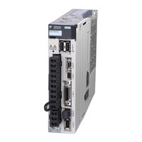
Yaskawa SGLCW User Manual (357 pages)
AC Servo Drives Linear Motor Analog Voltage and Pulse Train Reference SGDV Servopack
Brand:
Yaskawa
| Category:
Servo Drives
| Size: 9 MB
Table of Contents
Table of Contents
13
About this Manual
3
Safety Precautions
6
Applicable Standards
12
Table of Contents
13
Chapter 1 Outline
20
Part Names
20
Σ-V Series Servopacks
20
SERVOPACK Ratings and Specifications
21
Ratings
21
Basic Specifications
22
Speed/Position/Force Control Modes
24
SERVOPACK Internal Block Diagrams
25
Single-Phase 100 V, SGDV-R70F05A, -R90F05A, -2R1F05A Models
25
Single-Phase 100 V, SGDV-2R8F05A Model
25
Three-Phase 200 V, SGDV-R70A05A, -R90A05A, -1R6A05A Models
26
Three-Phase 200 V, SGDV-2R8A05A Model
26
Three-Phase 200 V, SGDV-3R8A05A, -5R5A05A, -7R6A05A Models
27
Three-Phase 200 V, SGDV-120A05A Model
27
Three-Phase 200 V, SGDV-180A05A, -200A05A Models
28
Three-Phase 200 V, SGDV-330A05A Model
28
Three-Phase 200 V, SGDV-470A05A, -550A05A Models
29
Three-Phase 200 V SGDV-590A05A, -780A05A Models
29
Three-Phase 400 V, SGDV-1R9D05A, -3R5D05A, -5R4D05A Models
30
Three-Phase 400 V, SGDV-8R4D05A, -120D05A Models
30
Three-Phase 400 V, SGDV-170D05A Model
31
Three-Phase 400 V, SGDV-210D05A, -260D05A Models
31
Three-Phase 400 V SGDV-280D05A, -370D05A Models
32
Examples of Servo System Configurations
33
Connecting to SGDV- F05A SERVOPACK
33
A05A Servopack
34
D05A Servopack
35
SERVOPACK Model Designation
36
Inspection and Maintenance
37
2 Panel Operator
38
Chapter 2 Panel Operator
39
Display Mode Selection
39
Panel Operator
39
Status Display Mode
40
Utility Function Mode (Fn )
41
How to Read a Parameter Explanation
42
Explanation Method for Parameter Setting Type
42
Explanation Method for Function Selection Type
42
Explanation Method for Tuning Parameters
43
Parameter Setting Mode (Pn )
44
Parameter Setting Mode for Parameter Setting Type
44
Parameter Setting Mode for Function Selection Type
47
Monitor Mode (un )
48
3 Wiring and Connection
49
Chapter 3 Wiring and Connection
50
Main Circuit Wiring
50
Names and Functions of Main Circuit Terminals
51
SERVOPACK Main Circuit Wire Size
52
Typical Main Circuit Wiring Examples
54
General Precautions for Wiring
57
Precautions When Using the SERVOPACK with a DC Power Input
58
Precautions When Using the SERVOPACK with Single-Phase, 200 V Power Input
60
Precautions When Using more than One SERVOPACK
63
Designing a Power on Sequence
64
I/O Signal Connections
65
I/O Signal (CN1) Names and Functions
65
I/O Signal Connector (CN1) Terminal Layout
67
Safety Function Signal (CN8) Names and Functions
68
Safety Function Signal (CN8) Terminal Layout
68
Example of I/O Signal Connections in Speed Control
69
Example of I/O Signal Connections in Position Control
70
Example of I/O Signal Connections in Force Control
71
I/O Signal Allocations
72
Input Signal Allocations
72
Output Signal Allocations
76
Examples of Connection to Host Controller
80
Connection Examples of Reference Input Circuits to SERVOPACK
80
Connection Examples of Sequence Input Circuits to SERVOPACK
82
Connection Examples of Output Circuits to SERVOPACK
83
Examples of Linear Scale Connection
86
Connection Example of a Linear Scale
86
CN2 Linear Scale Connector Terminal Layout
87
Connecting Regenerative Resistors
88
Setting Regenerative Resistor Capacity
90
Noise Control and Measures for Harmonic Suppression
91
Wiring for Noise Control
91
Precautions on Connecting Noise Filter
93
Connecting DC Reactor for Harmonic Suppression
95
4 Trial Operation
96
Chapter 4 Trial Operation
97
Inspection and Checking before Trial Operation
97
Trial Operation for Linear Servomotor Without Load
97
Trial Operation for Linear Servomotor Without Load from Host
97
Reference
97
Trial Operation for Linear Servomotor Without Load from Host Reference
97
Trial Operation with the Linear Servomotor Connected to the Machine
98
Test Without Motor Function
100
Limitations
100
Operating Procedure
101
Related Parameters
102
Operator Display During Testing Without Motor
102
5 Operation
104
Chapter 5 Operation
106
Control Selection
106
Setting Common Basic Functions
107
Servo on Signal
107
Servomotor Movement Direction
108
Overtravel
109
Stopping Servomotors after /S_ON Turned off or Alarm Occurrence
112
Power Loss Settings
114
Motor Maximum Speed
114
SEMI F47 Function
115
SEMI F47 Function (Force Limit Function for Low Power Supply Voltage for Main Circuit)
115
Setting Motor Overload Detection Level
118
Operating Using Speed Control with Analog Voltage Reference
120
Basic Settings for Speed Control
120
Reference Offset Adjustment
122
Soft Start
124
Speed Reference Filter
125
Zero Clamp Function
126
Encoder Pulse Output
128
Encoder Pulse Output Setting
130
Speed Coincidence Signal Setting
131
Operating Using Position Control with Pulse Train Reference
132
Basic Settings for Position Control Mode
132
Clear Signal
137
Electronic Gear
138
Smoothing
140
Positioning Completed Output Signal
141
Positioning Near Signal
142
Reference Pulse Inhibit Function
143
Operating Using Force Control with Analog Voltage Reference
145
Basic Settings for Force Control Mode
145
Adjustment of Reference Offset
146
Speed Limit in Force Control
148
Operating Using Speed Control with an Internally Set Speed
151
Basic Settings for Speed Control with an Internally Set Speed
151
Example of Operating with Internally Set Speed
153
Control Selection
155
Combination of Control Modes
155
Switching Internally Set Speed Control (Pn000.1 = 4, 5, or 6)
155
Switching Other than Internally Set Speed Control (Pn000.1 = 7, 8, 9, A, or B)
156
Limiting Force
157
Internal Force Limit
157
External Force Limit
158
Force Limiting Using an Analog Voltage Reference
159
Force Limiting Using an External Force Limit and Analog Voltage Reference
160
Checking Output Force Limiting During Operation
162
Setting Absolute Linear Scale
163
Setup Procedure
163
Setting the SEN Signal
164
Designing a Power on Sequence
165
Polarity Detection (Fn080)
165
Origin Setting (Fn020)
166
Absolute Encoder Reception Sequence
167
Output Signals Used in All Control Modes
171
Servo Alarm Output Signal (ALM) and Alarm Code Output Signals (ALO1, ALO2, and ALO3)
171
Warning Output Signal (/WARN)
172
Movement Detection Output Signal (/TGON)
173
Servo Ready Output Signal (/S-RDY)
173
Safety Function
174
Hard Wire Base Block (HWBB) Function
174
External Device Monitor (EDM1)
178
Application Example of Safety Functions
180
Confirming Safety Functions
181
Precautions for Safety Functions
181
6 Adjustments
182
Adjustments and Basic Adjustment Procedure
184
Adjustments
184
Basic Adjustment Procedure
185
Monitoring Analog Signals
186
Safety Precautions on Adjustment of Servo Gains
188
Chapter 6 Adjustments
184
Tuning-Less Function
191
Tuning-Less Operating Procedure
192
Advanced Autotuning (Fn201)
196
Advanced Autotuning
196
Advanced Autotuning (Fn201)
198
Advanced Autotuning
199
Advanced Autotuning Procedure
201
Related Parameters
205
Advanced Autotuning by Reference (Fn202)
206
Advanced Autotuning by Reference
206
Advanced Autotuning by Reference Procedure
211
Related Parameters
213
One-Parameter Tuning (Fn203)
214
One-Parameter Tuning
214
One-Parameter Tuning (Fn203)
215
One-Parameter Tuning
216
One-Parameter Tuning Procedure
216
One-Parameter Tuning Example
220
Related Parameters
221
Anti-Resonance Control Adjustment Function (Fn204)
222
Anti-Resonance Control Adjustment Function
222
Anti-Resonance Control Adjustment Function Operating Procedure
223
Related Parameters
227
Vibration Suppression Function (Fn205)
228
Vibration Suppression Function
228
Vibration Suppression Function Operating Procedure
229
Related Parameters
231
Servo Gain Adjustment Application Function
232
Feedforward Reference
233
Force Feedforward
234
Speed Feedforward
235
Proportional Control Operation (Proportional Operation Reference)
236
Using the Mode Switch (P/PI Switching)
237
Switching Gain Settings
241
Force Reference Filter
245
Position Integral Time Constant
247
Friction Compensation
248
Current Control Mode Selection
249
Current Gain Level Setting
250
Speed Detection Method Selection
250
7 Utility Functions (Fn )
251
Chapter 7 Utility Functions (Fn )
251
List of Utility Functions
252
Alarm History Display (Fn000)
253
JOG Operation (Fn002)
254
Origin Search (Fn003)
255
Program JOG Operation (Fn004)
256
Initializing Parameter Settings (Fn005)
261
Clearing Alarm History (Fn006)
262
Manual Zero-Adjustment of Analog Monitor Output (Fn00C)
263
Manual Gain-Adjustment of Analog Monitor Output (Fn00D)
265
Automatic Offset-Signal Adjustment of the Motor Current
267
Automatic Offset-Signal Adjustment of the Motor Current Detection
267
Manual Offset-Signal Adjustment of the Motor Current
268
Detection (Fn00F)
268
Fn00E
269
Write Prohibited Setting (Fn010)
269
Servomotor Model Display (Fn011)
271
Software Version Display (Fn012)
272
Resetting Configuration Error of Option Module (Fn014)
273
Vibration Detection Level Initialization (Fn01B)
274
Display of SERVOPACK and Servomotor ID (Fn01E)
276
Easyfft (Fn206)
277
Online Vibration Monitor (Fn207)
281
Software Reset (Fn030)
283
8 Monitor Modes (un )
284
Chapter 8 Monitor Modes
285
List of Monitor Modes
285
Operation in Monitor Mode
286
Monitor Display of Reference Pulse Counter (Un00C) and Feedback Pulse
287
Counter (Un00D)
287
Monitor Display of Reference Pulse Counter (Un00C) and Feedback Pulse Counter (Un00D)
287
Allowable Maximum Motor Speed and Encoder Output
288
Allowable Maximum Motor Speed and Encoder Output Resolution Monitor
288
Hall Sensor Signal Monitor
289
Monitoring Input Signals
290
Checking Input Signal Status
290
Interpreting Input Signal Display Status
290
Input Signal Display Example
291
Monitoring Output Signals
292
Checking Output Signal Status
292
Interpreting Output Signal Display Status
292
Output Signal Display Example
292
Monitor Display at Power on
293
Monitoring I/O Signals
293
9 Troubleshooting
294
Chapter 9 Troubleshooting
294
Troubleshooting
294
List of Alarms
295
Troubleshooting
295
Troubleshooting of Alarms
299
Warning Displays
313
List of Warnings
313
Troubleshooting of Warnings
314
Motor
314
Troubleshooting Malfunction Based on Operation and Conditions of the Servomotor
316
10 Appendix
321
Chapter 10 Appendix
322
Connection to Host Controller
322
Example of Connection to MP2200/MP2300 Motion Module SVA-01
322
Example of Connection to MP920 4-Axes Analog Module SVA-01
323
Example of Connection to Omron's Motion Control Unit
324
Example of Connection to Omron's Position Control Unit
324
Example of Connection to Omron's Position Control Unit
325
Connection to Mitsubishi's AD72 Positioning Unit (SERVOPACK in Speed Control Mode)
326
Connection to Mitsubishi's AD72 Positioning Unit
326
Connection to Mitsubishi's AD75 Positioning Unit (SERVOPACK in Position Control Mode)
327
List of Parameters
329
Parameters
329
List of Parameters
331
Parameters
332
Monitor Modes
350
Parameter Recording Table
351
Revision History
356
Advertisement
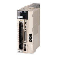
YASKAWA SGLCW User Manual (311 pages)
AC Servo Drives; Linear Motor Command Option Attachable Type
Brand:
YASKAWA
| Category:
Servo Drives
| Size: 11 MB
Table of Contents
About this Manual
3
Safety Precautions
7
Warranty
13
Applicable Standards
15
Table of Contents
16
Chapter 1 Outline
22
Σ-V Series Servopacks
22
Part Names
22
SERVOPACK Ratings and Specifications
23
Ratings
23
Basic Specifications
25
SERVOPACK Internal Block Diagrams
28
Single-Phase 100-V, SGDV-R70FE5A, -R90FE5A, -2R1FE5A Models
28
Single-Phase 100-V, SGDV-2R8FE5A Model
28
Single-Phase 200-V, SGDV-120AE5A008000 Model
29
Three-Phase 200-V, SGDV-R70AE5A, -R90AE5A, -1R6AE5A Models
29
Three-Phase 200-V, SGDV-2R8AE5A Model
30
Three-Phase 200-V, SGDV-3R8AE5A, -5R5AE5A, -7R6AE5A Models
30
Three-Phase 200-V, SGDV-120AE5A Model
31
Three-Phase 200-V, SGDV-180AE5A, -200AE5A Models
31
Three-Phase 200-V, SGDV-330AE5A Model
32
Three-Phase 200-V, SGDV-550AE5A Model
32
Three-Phase 400-V, SGDV-1R9DE5A, -3R5DE5A, -5R4DE5A Models
33
Three-Phase 400-V, SGDV-8R4DE5A, -120DE5A Models
33
Three-Phase 400-V, SGDV-170DE5A Model
34
Three-Phase 400-V, SGDV-260DE5A Model
34
Examples of Servo System Configurations
35
Connecting to SGDV- FE5A SERVOPACK
35
Ae5A Servopack
36
Connecting to SGDV- DE5A SERVOPACK
38
SERVOPACK Model Designation
39
Inspection and Maintenance
40
Chapter 2 Panel Display and Operation of Digital Operator
42
Panel Display
42
Status Display
42
Alarm and Warning Display
42
Hard Wire Base Block Display
42
Displays During Overtravel
42
Utility Function Mode (Fn )
43
Parameter
44
Parameter Classifications
44
Parameter Notation
44
Parameter Setting Methods
45
Monitor Mode (un )
47
Chapter 3 Wiring and Connection
49
Main Circuit Wiring
49
Main Circuit Terminals
49
Using a Standard Power Supply Input (Single-Phase 100-V, Three-Phase 200-V, or Three-Phase 400-V)
50
General Precautions for Wiring
58
Using the SERVOPACK with Single-Phase, 200-V Power Input
59
Using the SERVOPACK with a DC Power Input
62
Using more than One SERVOPACK
64
I/O Signal Connections
65
I/O Signal (CN1) Names and Functions
65
Safety Function Signal (CN8) Names and Functions
66
Example of I/O Signal Connections
67
I/O Signal Allocations
68
Input Signal Allocations
68
Output Signal Allocation
70
Connection to Host Controller
71
Sequence Input Circuits
71
Sequence Output Circuits
73
Wiring Communications Using Command Option Modules
75
Linear Scale Connections
76
Linear Scale Signal (CN2) Names and Functions
76
Connection Example of a Linear Scale
76
Serial Converter Unit Specifications
78
Regenerative Resistors Connections
80
Connecting Regenerative Resistors
80
Setting Regenerative Resistor Capacity
82
Noise Control and Measures for Harmonic Suppression
83
Wiring for Noise Control
83
Precautions on Connecting Noise Filter
85
Connecting AC/DC Reactor for Harmonic Suppression
87
Chapter 4 Operation
90
Option Module Function Settings
90
Setting Switches S1 and S2 for Option Module Functions
90
Settings for Common Basic Functions
91
Inspection and Checking before Operation
91
Linear Servomotor Movement Direction
92
Overtravel
93
Electronic Gear
96
Encoder Output Pulse
99
Encoder Output Pulse Setting
101
Holding Brakes
102
Stopping Linear Servomotor after Receiving Servo off Command or Alarm Occurrence
106
Instantaneous Power Interruption Settings
108
Motor Maximum Speed
108
SEMI-F47 Function (Force Limit Function for Low Power Supply Voltage for Main Circuit)
109
Setting Motor Overload Detection Level
112
Test Without Motor Function
114
Related Parameters
114
Limitations
115
Digital Operator Display During Testing Without Motor
116
Limiting Force
117
Internal Force Limit
117
External Force Limit
118
Checking Output Force Limiting During Operation
119
Setting Absolute Linear Scale
120
Setup Procedure
120
Origin Setting (Fn020)
121
Polarity Detection (Fn080)
122
Absolute Linear Scale Reception Sequence
123
Other Output Signals
126
Servo Alarm Output Signal (ALM)
126
Warning Output Signal (/WARN)
126
Movement Detection Output Signal (/TGON)
127
Servo Ready Output Signal (/S-RDY)
127
Safety Function
128
Hard Wire Base Block (HWBB) Function
128
External Device Monitor (EDM1)
133
Application Example of Safety Functions
135
Confirming Safety Functions
136
Connecting a Safety Device
137
Precautions for Safety Functions
138
Chapter 5 Adjustments
141
Adjustments and Basic Adjustment Procedure
141
Adjustments
141
Basic Adjustment Procedure
142
Monitoring Analog Signals
143
Safety Precautions on Adjustment of Servo Gains
146
Tuning-Less Function
148
Tuning-Less Levels Setting (Fn200) Procedure
151
Advanced Autotuning (Fn201)
154
Advanced Autotuning
154
Advanced Autotuning Procedure
157
Related Parameters
162
Advanced Autotuning by Reference (Fn202)
163
Advanced Autotuning by Reference
163
Advanced Autotuning by Reference Procedure
165
Related Parameters
167
One-Parameter Tuning (Fn203)
170
One-Parameter Tuning
170
One-Parameter Tuning Procedure
171
One-Parameter Tuning Example
177
Related Parameters
178
Anti-Resonance Control Adjustment Function (Fn204)
179
Anti-Resonance Control Adjustment Function
179
Anti-Resonance Control Adjustment Function Operating Procedure
180
Related Parameters
184
Vibration Suppression Function (Fn205)
185
Vibration Suppression Function
185
Vibration Suppression Function Operating Procedure
186
Related Parameters
189
Additional Adjustment Function
190
Switching Gain Settings
190
Friction Compensation
196
Current Control Mode Selection
197
Current Gain Level Setting
197
Speed Detection Method Selection
197
Compatible Adjustment Function
198
Feedforward Reference
198
Using the Mode Switch (P/PI Switching)
198
Force Reference Filter
203
Position Integral Time Constant
205
Chapter 6 Utility Functions (Fn )
207
List of Utility Functions
207
Alarm History Display (Fn000)
208
JOG Operation (Fn002)
209
Origin Search (Fn003)
211
Program JOG Operation (Fn004)
213
Initializing Parameter Settings (Fn005)
219
Clearing Alarm History (Fn006)
220
Offset Adjustment of Analog Monitor Output (Fn00C)
221
Gain Adjustment of Analog Monitor Output (Fn00D)
223
Automatic Offset-Signal Adjustment of the Motor Current Detection
225
Automatic Offset-Signal Adjustment of the Motor Current
225
Detection (Fn00F)
226
Manual Offset-Signal Adjustment of the Motor Current
226
Fn00E
227
Fn00F
227
Write Prohibited Setting (Fn010)
227
Servomotor Model Display (Fn011)
229
Software Version Display (Fn012)
230
Resetting Configuration Error of Option Module (Fn014)
231
Vibration Detection Level Initialization (Fn01B)
232
Display of SERVOPACK and Servomotor ID (Fn01E)
234
Software Reset (Fn030)
235
Easyfft (Fn206)
236
Online Vibration Monitor (Fn207)
241
Chapter 7 Monitor Modes (un )
243
List of Monitor Modes
244
Monitor Displays
245
Chapter 8 Troubleshooting
246
Troubleshooting
246
List of Alarms
247
Troubleshooting
247
Troubleshooting of Alarms
251
Warning Displays
268
List of Warnings
268
Troubleshooting of Warnings
270
Troubleshooting Malfunction Based on Operation and Conditions of the Linear Servomotor
274
Chapter 9 Appendix
280
List of Parameters
280
Utility Functions
280
Parameters
281
Monitor Modes
301
Parameter Recording Table
302
Index
307
Revision History
310
YASKAWA SGLCW User Manual (276 pages)
AC Servodrive, Linear Motor, Communications Reference
Brand:
YASKAWA
| Category:
Servo Drives
| Size: 5 MB
Table of Contents
About this Manual
3
Safety Precautions
6
Applicable Standards
12
Table of Contents
13
Chapter 1 Outline
18
Σ-V Series Servopacks
18
Part Names
18
SERVOPACK Ratings and Specifications
19
Ratings
19
Basic Specifications
20
MECHATROLINK-II Function Specifications
22
Examples of Servo System Configurations
23
Connecting to SGDV- F15A SERVOPACK
23
A15A Servopack
24
Connecting to SGDV
24
D15A Servopack
25
Connecting to SGDV
25
SERVOPACK Model Designation
26
Inspection and Maintenance
27
Chapter 2 Panel Display and Operation of Digital Operator
29
Panel Display
29
Status Display
29
Alarm and Warning Display
29
Mode Test Without Motor Display
29
Monitor Mode (un )
30
Utility Function Mode (Fn )
30
How to Read a Parameter Explanation
32
Explanation Method for Parameter Setting Type
32
Explanation Method for Function Selection Type
32
Explanation Method for Tuning Parameters
32
Parameter Setting Mode (Pn )
33
Parameter Setting Mode for Parameter Setting Type
33
Parameter Setting Mode for Function Selection Type
35
Monitor Mode (un )
36
Chapter 3 Wiring and Connection
38
Main Circuit Wiring
38
Names and Functions of Main Circuit Terminals
39
SERVOPACK Main Circuit Wire Size
40
Typical Main Circuit Wiring Examples
42
General Precautions for Wiring
45
Precautions When Using the SERVOPACK with a DC Power Input
46
Precautions When Using the SERVOPACK with Single-Phase, 200 V Power Input
48
Precautions When Using more than One SERVOPACK
51
Designing a Power on Sequence
52
I/O Signal Connections
53
I/O Signal (CN1) Names and Functions
53
I/O Signal Connector (CN1) Terminal Layout
54
Safety Function Signal (CN8) Names and Functions
55
Safety Function Signal (CN8) Terminal Layout
55
Example of I/O Signal Connections
56
I/O Signal Allocation
57
Input Signal Allocation
57
Output Signal Allocation
58
Examples of Connection to Host Controller
60
Connection Examples of Input Circuits to SERVOPACK
60
Connection Examples of Sequence Input Circuits to SERVOPACK
61
Connection Examples of Output Circuits to SERVOPACK
62
Wiring MECHATROLINK-II Communications
64
Examples of Encoder Connection
65
Connection Example of an Encoder
65
CN2 Encoder Connector Terminal Layout
66
Connecting Regenerative Resistors
67
Setting Regenerative Resistor Capacity
68
Noise Control and Measures for Harmonic Suppression
69
Wiring for Noise Control
69
Precautions on Connecting Noise Filter
71
Connecting DC Reactor for Harmonic Suppression
73
Chapter 4 Operation
74
MECHATROLINK-II Communications Settings
75
Setting Switches SW1 and SW2
75
MECHATROLINK-II Commands
76
Setting Common Basic Functions
77
Servomotor Movement Direction
77
Overtravel
78
Stopping Method for Servomotor after Servo off or Alarm Occurrence
81
Power Loss Settings
83
Motor Maximum Speed
83
Force Limit Function for Low Power Supply Voltage for Main Circuit (SEMI-F47 Function)
84
Setting Motor Overload Detection Level
86
Trial Operation
88
Inspection and Checking before Trial Operation
88
Trial Operation Via MECHATROLINK-II
89
Electronic Gear
90
Test Without Motor Function
92
Limitations
92
Related Parameters
93
Digital Operator Display During Testing Without Motor
94
Safety Function
95
Hard Wire Base Block (HWBB) Function
95
External Device Monitor (EDM1)
100
Application Example of Safety Functions
102
Confirming Safety Functions
103
Precautions for Safety Functions
103
Chapter 5 Adjustments
104
Adjustments and Basic Adjustment Procedure
106
Adjustments
106
Basic Adjustment Procedure
107
Monitoring Analog Signals
108
Safety Precautions on Adjustment of Servo Gains
110
Tuning-Less Function
113
Tuning-Less Operating Procedure
115
Advanced Autotuning (Fn201)
117
Advanced Autotuning
117
Advanced Autotuning (Fn201)
120
Advanced Autotuning
120
Advanced Autotuning Procedure
122
Related Parameters
126
Advanced Autotuning by Reference (Fn202)
127
Advanced Autotuning by Reference
127
Advanced Autotuning by Reference Procedure
131
Related Parameters
133
One-Parameter Tuning (Fn203)
134
One-Parameter Tuning
134
One-Parameter Tuning (Fn203)
135
One-Parameter Tuning
136
One-Parameter Tuning Procedure
137
One-Parameter Tuning Example
140
Related Parameters
141
Anti-Resonance Control Adjustment Function (Fn204)
142
Anti-Resonance Control Adjustment Function
142
Anti-Resonance Control Adjustment Function Operating Procedure
143
Related Parameters
147
Vibration Suppression Function (Fn205)
148
Vibration Suppression Function
148
Vibration Suppression Function Operating Procedure
149
Related Parameters
151
Servo Gain Adjustment Application Function
152
Feedforward Reference
153
Using the Mode Switch (P/PI Switching)
153
Switching Gain Settings
157
Force Reference Filter
161
Position Integral Time Constant
163
Friction Compensation
164
Current Control Mode Selection
166
Current Gain Level Setting
166
Speed Detection Method Selection
166
Chapter 6 Utility Functions (Fn )
168
List of Utility Functions
168
Alarm History Display (Fn000)
169
JOG Operation (Fn002)
170
Origin Search (Fn003)
172
Program JOG Operation (Fn004)
174
Initializing Parameter Settings (Fn005)
179
Clearing Alarm History (Fn006)
180
Manual Zero-Adjustment of Analog Monitor Output (Fn00C)
181
Manual Gain-Adjustment of Analog Monitor Output (Fn00D)
183
Automatic Offset-Signal Adjustment of the Motor Current Detection
185
Automatic Offset-Signal Adjustment of the Motor Current
185
Detection (Fn00F)
186
Manual Offset-Signal Adjustment of the Motor Current
186
Fn00E
187
Write Prohibited Setting (Fn010)
187
Write Prohibited Setting (Fn010)
188
Servomotor Model Display (Fn011)
189
Software Version Display (Fn012)
190
Resetting Configuration Error of Option Module (Fn014)
191
Vibration Detection Level Initialization (Fn01B)
192
Display of SERVOPACK and Servomotor ID (Fn01E)
194
Easyfft (Fn206)
195
Online Vibration Monitor (Fn207)
199
Software Reset (Fn030)
201
Chapter 7 Monitor Modes (un )
202
List of Monitor Modes
203
Monitor Mode Display
204
Chapter 8 Troubleshooting
205
List of Alarms
206
Troubleshooting
206
Troubleshooting of Alarms
210
Warning Displays
226
List of Warnings
226
Troubleshooting of Warnings
227
The Servomotor
227
Troubleshooting Malfunction Based on Operation and Conditions of the Servomotor
230
Chapter 9 Appendix
236
List of Parameters
236
Utility Functions
236
Parameters
237
Monitor Modes
267
Parameter Recording Table
268
Parameter Recording Table
269
Revision History
275
Advertisement
Advertisement
Related Products
YASKAWA SGLGW
YASKAWA SGLFW
YASKAWA SGLTW
YASKAWA SGLC
YASKAWA SGLG
YASKAWA SGLF
YASKAWA SGLT
YASKAWA SGMVH-5ED B Series
YASKAWA SGDV-3R5DE5A
YASKAWA SGD7S-R70A20A000F41B
Yaskawa Categories
Controller
DC Drives
Servo Drives
Robotics
Control Unit
More Yaskawa Manuals
Login
Sign In
OR
Sign in with Facebook
Sign in with Google
Upload manual
Upload from disk
Upload from URL